WO2012011276A1 - リアクトル - Google Patents
リアクトル Download PDFInfo
- Publication number
- WO2012011276A1 WO2012011276A1 PCT/JP2011/004097 JP2011004097W WO2012011276A1 WO 2012011276 A1 WO2012011276 A1 WO 2012011276A1 JP 2011004097 W JP2011004097 W JP 2011004097W WO 2012011276 A1 WO2012011276 A1 WO 2012011276A1
- Authority
- WO
- WIPO (PCT)
- Prior art keywords
- coil
- reactor
- core
- core member
- gap
- Prior art date
- Legal status (The legal status is an assumption and is not a legal conclusion. Google has not performed a legal analysis and makes no representation as to the accuracy of the status listed.)
- Ceased
Links
Images


Classifications
-
- H—ELECTRICITY
- H01—ELECTRIC ELEMENTS
- H01F—MAGNETS; INDUCTANCES; TRANSFORMERS; SELECTION OF MATERIALS FOR THEIR MAGNETIC PROPERTIES
- H01F37/00—Fixed inductances not covered by group H01F17/00
-
- H—ELECTRICITY
- H01—ELECTRIC ELEMENTS
- H01F—MAGNETS; INDUCTANCES; TRANSFORMERS; SELECTION OF MATERIALS FOR THEIR MAGNETIC PROPERTIES
- H01F3/00—Cores, Yokes, or armatures
- H01F3/10—Composite arrangements of magnetic circuits
- H01F3/14—Constrictions; Gaps, e.g. air-gaps
-
- H—ELECTRICITY
- H01—ELECTRIC ELEMENTS
- H01F—MAGNETS; INDUCTANCES; TRANSFORMERS; SELECTION OF MATERIALS FOR THEIR MAGNETIC PROPERTIES
- H01F17/00—Fixed inductances of the signal type
- H01F17/04—Fixed inductances of the signal type with magnetic core
- H01F17/045—Fixed inductances of the signal type with magnetic core with core of cylindric geometry and coil wound along its longitudinal axis, i.e. rod or drum core
-
- H—ELECTRICITY
- H01—ELECTRIC ELEMENTS
- H01F—MAGNETS; INDUCTANCES; TRANSFORMERS; SELECTION OF MATERIALS FOR THEIR MAGNETIC PROPERTIES
- H01F27/00—Details of transformers or inductances, in general
- H01F27/28—Coils; Windings; Conductive connections
- H01F27/2847—Sheets; Strips
Definitions
- the present invention relates to a reactor suitably used for, for example, an electric circuit or an electronic circuit.
- a reactor is a passive element that uses a winding, for example, various electric currents such as prevention of harmonic current in a power factor correction circuit, smoothing of current pulsation in a current type inverter or chopper control, and boosting of a DC voltage in a converter. Used in circuits and electronic circuits.
- a solar power generation system is being introduced for residential use.
- a solar cell power generation system includes, for example, a solar cell module that converts solar light energy into electric power, and a power conditioner that converts DC power generated by the solar cell module into AC power in order to perform system linkage.
- a distribution board that distributes the AC power converted by the power conditioner to various places in the house and to the electric power company.
- a reactor is usually used for the power conditioner.
- hybrid vehicles and electric vehicles capable of reducing carbon dioxide emissions have been researched and developed. Its spread is also being promoted.
- a booster circuit is used in the drive control system of the drive motor in order to improve the driving efficiency of the drive motor, and a reactor is usually incorporated in this booster circuit.
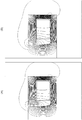
- FIG. 21 is a diagram showing a configuration of a reactor in the conventional technology.
- FIG. 21A shows the reactor disclosed in Patent Document 1
- FIG. 21B shows the reactor disclosed in Patent Document 2.
- a reactor for a power conditioner of the solar power generation system is disclosed in Patent Document 1, for example.
- a reactor PDA disclosed in Patent Document 1 includes an annular core composed of two opposing magnetic core joints and a plurality of magnetic core legs disposed between the magnetic core joints. 201, wherein the magnetic core joint portion has a projection directed toward the magnetic core leg portion, a gap is formed between the magnetic core leg portion and the magnetic core joint portion, and the magnetic core leg.
- the portion is composed of an integral magnetic core block, and the ratio A / B between the length A of the projection of the magnetic core joint and the average length B in the magnetic path direction of the magnetic core leg is 0.3 or more
- the reactor is 8.0 or less, and is a reactor in which a coil 202 is wound around the magnetic core leg (see FIG. 3 of Patent Document 1). Since the reactor having such a configuration has been optimized for the ratio A / B, it is possible to obtain a highly efficient reactor that suppresses an increase in copper loss due to leakage magnetic flux in the gap portion, thereby improving the power conversion efficiency.
- Patent Document 1 discloses that a high power conditioner can be manufactured.
- the reactor PDB disclosed in Patent Document 2 includes a coil 301, an inner core 302 disposed inside the coil 301, and an outer core 303 disposed outside the coil 301.
- the heat conductivity at 25 ° C. is made of a high heat conductive material having a thermal conductivity of 100 W / m ⁇ K or more.
- Patent Document 2 discloses that the reactor having such a configuration can improve the heat dissipation of the core piece 302b by the high thermal conductivity gap material 302a.
- the reactor for such use is required not only for high efficiency as in Patent Document 1 and heat dissipation as in Patent Document 2, but also for relatively large inductance, noise reduction, and loss reduction.
- a power conditioner of a solar cell power generation system is often installed indoors, it is important to reduce noise for a reactor used therefor.
- the reactor is operated at a high frequency so that, for example, an audible band of about 18 kHz or more is generated when noise occurs, the loss increases due to such high frequency, so the low loss Is important.
- the present invention has been made in view of the above circumstances, and an object thereof is to provide a reactor having a relatively large inductance, low loss, and low noise.
- a reactor according to the present invention includes a first core portion including a coil in which a strip-shaped conductor member whose width direction extends along an axial direction is included, and a second core portion disposed in a core portion of the coil, Each inner surface of the first core portion facing each end of the coil is parallel in a region covering at least each end portion of the coil, and one end portion of the second core portion is the first core portion. Is disposed with a gap between the peripheral surface of the one end and the peripheral surface of the opening. For this reason, the reactor according to the present invention can have a relatively large inductance, low loss, and low noise.
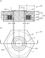
- FIG. 1 is a diagram illustrating a configuration of a reactor in the first embodiment.
- 1A is a longitudinal sectional view including the central axis of the coil 1A and cut along the central axis direction
- FIG. 1B is a top view when viewed in plan from the central axis direction. is there.
- a line AA shown in FIG. 1B is a cutting line in the longitudinal sectional view of FIG.
- FIG. 2 is a diagram for explaining the relationship between the width W and the thickness t in the conductor member constituting the coil of the reactor according to the first embodiment.
- FIG. 3 is a diagram for explaining the relationship between the coil winding structure and eddy current loss.
- FIG. 3A shows the case of a flat-wise winding structure
- FIG. 3B shows the case of an edge-wise winding structure.
- FIG. 4 is a graph showing the relationship between the frequency f and the loss in the reactor for each coil winding structure.
- FIG. 5 is a diagram for explaining the vibration and noise of the
- the reactor according to the first embodiment includes a coil, a first core part including the coil, and a second core part disposed at a core part of the coil, and the coil includes a strip-shaped conductor member, It is configured by winding so that the width direction of the conductor member is along the axial direction of the coil, and one inner surface of the first core portion facing the one end portion of the coil in the axial direction and the axial direction in the axial direction.
- the other inner surface of the first core portion facing the other end portion of the coil is parallel to at least one end portion of the coil and each end portion of the other end portion, and is one of the second core portions.
- the end portion is disposed in the opening formed in the first core portion with a gap between the peripheral surface of the one end portion and the peripheral surface of the opening portion.
- the reactor DA according to the first embodiment having such a configuration includes, for example, a coil 1A, a core member 2A, and a gap member 3 as shown in FIG.
- the core member 2A is formed of, for example, a magnetically (for example, magnetic permeability) isotropic material, and includes an upper core member 21A and a lower core member 22A.
- the upper core member 21A has a polygonal shape having a predetermined thickness.
- the upper core member 21a is a hexagonal plate-like body, and the upper core member has a predetermined thickness.
- a cylindrical side wall core member 21b extending in a substantially vertical direction from the outer peripheral edge of 21a.
- the cross section perpendicular to the axial direction of the side wall core member 21b of the cylindrical body has a hexagonal shape (outer shape) because the upper end core member 21a has a hexagonal shape in the example shown in FIG.
- the coil 1A having a cylindrical pancake structure is arranged in the cylindrical body of the side wall core member 21b, there is a circular opening in the hexagon.
- An opening APA that is a through opening is formed in the upper end core member 21a.
- the opening APA is a circular hole having a diameter of a predetermined length centered on the center position (geometric gravity center position) of the upper end core member 21 a.
- the lower core member 22A has the same shape as the upper end core member 21a and has a polygonal shape having a predetermined thickness. In the example shown in FIG.
- the convex piece core member 22b is a cylindrical body having an outer diameter of a predetermined length centered on the center position (geometric gravity center position) of the lower end core member 22a. The outer diameter gradually increases from the middle to the lower end core member 22a, and the side surface of the cylindrical body is tapered.
- the convex piece core member 22b is solid but may be hollow. Further, for example, a predetermined fluid such as air or water is allowed to flow through the hollow portion to increase the heat dissipation of the reactor. It may be improved.
- the end portion of the side wall core member 21b in the upper core member 21A having such a structure is connected (connected) substantially gaplessly to the peripheral portion of the lower end core member 22a in the lower core member 22A. Consists of. Accordingly, a space for accommodating the coil 1A is formed between the upper end core member 21a and the lower end core member 22a and between the side wall core member 21b and the convex piece core member 22b.
- the tip of the convex core member 22b is inserted into the opening APA of the upper core member 21a, and the convex core member 22b
- a gap GA is provided between the peripheral surface (outer peripheral surface) at the tip and the peripheral surface (inner peripheral surface) of the opening APA, and the gap GA is disposed in the opening APA. That is, the diameter of the opening APA is larger than the diameter of the convex core member 22b.
- the tip of the convex piece core member 22b slightly protrudes outward from the outer surface of the upper end core member 21a.
- the upper end core member 21a, the side wall core member 21b, and the lower end core member 22a of the lower core member 22A in the upper core member 21A correspond to an example of the first core portion including the coil 1A, and the lower core member 22A.
- the convex piece core member 22b corresponds to an example of the second core portion disposed in the core portion of the coil 1A.
- the first core portion (in the example shown in FIG. 1, the upper end core member 21a, the side wall core member 21b, and the lower end core member 22a) functions to reduce magnetic flux leaking to the outside, and is defined by, for example, specifications.
- the maximum relative magnetic permeability is designed based on the magnitude of the leakage magnetic flux allowed in the reactor DA.
- the maximum relative permeability of the first core portion is preferably about 100 or more, for example, as the reactor DA that is suitably used for the power conditioner of the solar cell power generation system.
- the maximum relative permeability of the second core portion affects the inductance of the reactor DA. It is designed based on the required inductance.
- a power conditioner of a solar cell power generation system is also required to have stability of inductance characteristics that an inductance change is small with respect to a current change so that the power conditioner operates stably with respect to the current change. When the inductance is relatively small, the change in current becomes steep, so that the inductance should be relatively large. However, increasing inductance increases the size of reactor DA.
- the average value of the current flowing through the reactor DA is about 20 A, and is about 30 A at the maximum, and corresponds to a wide current range. There is no need. That is, in the power conditioner of the solar battery power generation system, since the current exceeding the predetermined range does not flow, the stability of the inductance characteristic is not required up to a large current. For this reason, about 1 mH is preferable in the vicinity of the current value 20A from the balance between the two, and the maximum relative permeability of the second core portion is set in consideration of the gap effect and the like.
- the core member 2A is formed by molding, for example, a soft magnetic powder alone or a mixture of a soft magnetic powder and a nonmagnetic powder from the viewpoint of easy realization of desired magnetic characteristics and ease of forming a desired shape.
- a soft magnetic powder alone or a mixture of a soft magnetic powder and a nonmagnetic powder from the viewpoint of easy realization of desired magnetic characteristics and ease of forming a desired shape.
- the mixing ratio of soft magnetic powder and non-magnetic powder can be adjusted relatively easily. By appropriately adjusting the mixing ratio, the magnetic characteristics of the core member 2A can be changed to desired magnetic characteristics. It can be easily realized.
- it since it is a soft magnetic powder alone or a mixture of soft magnetic powder and non-magnetic powder, it can be formed into various shapes, and the shape of the core member 2A can be easily formed into each desired shape. It becomes.
- the upper core member 21A and the lower core member 22A are preferably made of the same raw material from the viewpoint of cost reduction.
- This soft magnetic powder is a ferromagnetic metal powder. More specifically, for example, pure iron powder, iron-based alloy powder (Fe—Al alloy, Fe—Si alloy, Sendust, Permalloy, etc.) and amorphous powder, Furthermore, the iron powder etc. with which electric insulation films, such as a phosphoric acid system chemical film, were formed on the surface are mentioned.
- These soft magnetic powders can be produced, for example, by a method of making fine particles by an atomizing method or the like, or a method of finely pulverizing iron oxide or the like and then reducing it.
- the upper core member 21A and the lower core member 22A have predetermined magnetic flux density-relative magnetic permeability characteristics.
- predetermined magnetic flux density-relative magnetic permeability characteristics For example, by using known conventional means, iron powder as soft magnetic powder and non-magnetic powder as non-magnetic powder are used.
- the magnetic flux density-relative permeability characteristic is a change in relative permeability with respect to a change in magnetic flux density.
- the upper core member 21A is formed by integrally forming the upper end core member 21a and the side wall core member 21b, but the upper end core member 21a and the side wall core member 21b are individually formed. It may be formed by connecting (connecting) these later.
- the lower core member 22A is formed by integrally forming the lower end core member 22a and the convex piece core member 22b, but the lower end core member 22a and the convex piece core member 22b. These may be formed separately and then connected (connected).
- the core member 2A is divided into the upper core member 21A and the lower core member 22A, but the way of dividing each member is arbitrary.
- the coil 1A is formed by winding a long conductor member a predetermined number of times, and generates a magnetic field when energized.
- the coil 1A is configured by winding a strip-shaped conductor member so that the width direction of the conductor member is along the axial direction of the coil 1A.
- the coil 1A is disposed in the above-described space between the upper end core member 21a and the lower end core member 22a and between the side wall core member 21b and the convex core member 22b, and the coil 1A.
- the protruding piece core member 22b is disposed so as to penetrate the coil 1A in the core portion of the core.
- the reactor DA according to the present embodiment is a so-called pot-type reactor that houses the cored coil 1A in the internal space of the core member 2A. Furthermore, in the reactor DA of the present embodiment, one inner surface of the upper end 1 core member 21a facing the one end of the coil 1A in the axial direction and the lower end 1 core of the other end of the coil 1A in the axial direction. The other inner surface of 22a is configured to be parallel to at least an area covering each end of the one end and the other end of the coil 1A.
- the band shape means a case where the width W is larger than the thickness t, that is, W> t (W / t> 1) between the width W and the thickness t.
- W> t W / t> 1
- the coil 1A of the present embodiment has a so-called flat-wise winding structure.
- a reactor DA (FIG. 1, FIG. 3 (A)) provided with a coil 1 ⁇ / b> A of a flatwise winding structure in which such a conductor member is wound so as to overlap in the radial direction, and the conductor member is in the axial direction.
- the eddy current loss of the reactor DH (FIG. 3B) including the coil 1H having the edgewise winding structure wound so as to overlap is described below.
- the eddy current is generated in a plane (orthogonal plane) perpendicular to the lines of magnetic force, thereby generating a loss.
- the magnitude of the eddy current is proportional to the area intersecting the magnetic flux lines, that is, the area of a continuous surface perpendicular to the magnetic force lines.
- the magnetic lines of force are along the axial direction in the coil, so the eddy current is a radial surface perpendicular to the axial direction of the conductor constituting the coil. It is proportional to the area.
- the conductor member has a large area in the radial direction, is likely to generate eddy current, and loss caused by eddy current rather than loss caused by electric resistance. Is more dominant. Therefore, in the edgewise winding structure, as shown in FIG. 4, the loss increases with an increase in frequency depending on the frequency of the energized current.
- the conductor member has a small area in the radial direction and hardly generates eddy currents.
- the axial area is large. Therefore, in the flatwise winding structure, as shown in FIG. 4, almost no eddy current is generated, and the loss is only due to the electrical resistance, and is substantially constant regardless of the frequency of the energized current.
- the edgewise winding structure has a structure in which the conductor members are stacked in the axial direction.
- the width direction of the conductor member is substantially coincident with the axial direction and is continuous. Therefore, the flat-wise winding structure generates heat generated in the coil more effectively than the edge-wise winding structure. Conducts heat to the core.
- the reactor DA provided with the coil 1A having the flatwise winding structure is superior to the reactor DH including the coil 1H having the edgewise winding structure in terms of the loss and heat conduction.
- the reactor DA includes the coil 1A and the first core portion (upper end core member 21a, side wall core member 21b, and lower end core member 22a), as shown by a broken line in FIG.
- the heat conduction member 6 that conducts heat relatively well may be filled in the gap formed between the two.
- the reactor DA having such a configuration can conduct heat generated in the coil 1A to the first core portion surrounding the coil 1A via the heat conducting member, thereby improving heat dissipation.
- the heat conducting member include a polymer member having a relatively good thermal conductivity (a polymer member having a relatively high conductivity). This polymer member is, for example, an epoxy resin having excellent adhesiveness.
- the heat conducting member may be an insulating material such as BN ceramic (boron nitride ceramic) or may be filled with a compound. With such a heat conducting member, the insulation can be improved.
- the said conductor member is strip
- the area in the radial direction is smaller than that of a reactor formed of a conductor member having a rectangular cross section in which the thickness t is longer than the width W.
- the eddy current loss can be reduced for the same reason as the reason why the coil 1A having the flatwise winding structure is superior to the coil DH having the edgewise winding structure in terms of the loss.
- the ratio t / W of the width W to the thickness t of the conductor member is 1/10 or less (t / W ⁇ 1/10, 10t ⁇ W)
- the occurrence of eddy current loss is greatly reduced. be able to.
- the one inner surface of the first core portion (upper end core member 21a) facing the one end portion of the coil 1A in the axial direction and the coil 1A in the axial direction are arranged.
- the other inner surface of the first core portion (the lower end core member 22a) facing the other end portion is configured to be parallel to at least a region covering each end portion of the one end portion and the other end portion of the coil 1A. It has been done.
- the first core is opposed to both the upper and lower end surfaces of the coil 1A. If the reactor DA is not configured so that the upper and lower inner wall surfaces (upper wall surface and lower wall surface) of the portion are parallel in at least the region covering the end of the coil 1A, the magnetic flux lines passing through the inside of the coil 1A This is because (line of magnetic force) does not become substantially parallel to the axial direction.
- the interval at the innermost side position (innermost peripheral position) of the coil 1A is L1
- the outermost side position of the coil 1A When the interval at (the outermost circumferential position) is L2, and the average value of the intervals from the innermost circumferential position to the outermost circumferential position is L3, the first core portion at the innermost circumferential position of the coil 1A
- the difference (L1-L2) between the distance L1 between the upper wall surface and the lower wall surface and the distance L2 between the upper wall surface and the lower wall surface of the first core portion at the outermost peripheral position of the coil 1A is divided by the average value L3.
- the value (L1-L2) / L3 obtained in this way is defined as the parallelism.
- the average value L3 is an average value of the intervals at a plurality of positions that are cut at a predetermined interval between the innermost peripheral position and the outermost peripheral position.
- the present inventor verified the distribution of magnetic flux lines while changing the parallelism in various ways. For example, when the parallelism is 1/100, the inside of the coil 1 is While the magnetic flux lines that pass through are parallel to the axial direction, when the parallelism is -1/10 or 1/10, the magnetic flux lines that pass through the inside of the coil 1 are not parallel to the axial direction. In order to make the magnetic flux lines passing through the inside of the coil 1A in parallel under such verification, the absolute value of the parallelism is preferably 1/50 or less.
- the both ends of the coil 1A are connected to unillustrated terminals for supplying power to the coil 1A from the outside, respectively, and these terminals are provided on the first core portion, for example, the upper end core member 21a. It is provided so as to face the outside of the first core part through the through hole.
- the gap member 3 is sandwiched by a gap GA formed at a predetermined interval (gap length) between the peripheral surface (outer peripheral surface) at the tip of the convex core member 22b and the peripheral surface (inner peripheral surface) of the opening APA. It is a member.
- the gap member 3 maintains the gap length, and fixes the upper end core member 21a of the upper core member 21A and the convex core member 22b of the lower core member 22A.
- the gap member 3 includes a donut-shaped cap portion in a plan view and a cylindrical gap portion that is suspended from the lower surface of the cap portion and is sandwiched between the gaps GA.
- a vertical cross section perpendicular to the circumferential direction of the gap member 3 is substantially T-shaped.
- Such a gap member 3 is formed of, for example, epoxy resin or alumina. Then, by adjusting the gap length, it is possible to control the inductance variation in a desired current range.
- the reactor DA in the first embodiment can also reduce product variations in inductance.
- the gap length varies depending on the manufacturing accuracy of the material sandwiched between the gaps and the application conditions such as the adhesive. If the value is ⁇ n and the design value is g, ⁇ (g + ⁇ n ) (where ⁇ is the sum of 1 to the number of gaps for n).
- the variation of the variation value ⁇ causes a product variation in the inductance to be relatively large. Therefore, in the conventional reactors PDA and PDB, if the number of gaps is reduced in order to improve the accuracy of the gap length, it is necessary to increase the gap length in order to obtain equivalent characteristics. For this reason, the leakage magnetic flux which leaks from a gap increases, and since this leakage magnetic flux penetrates the conductor of a coil, an eddy current loss will become large, and, as a result, the efficiency of a reactor will fall.
- the gap GA has the convex core member 22b inserted into the opening APA of the upper end core member 21a, and the peripheral surface (outer peripheral surface) and the opening at the tip of the convex core member 22b. It is formed between the peripheral surface (inner peripheral surface) of APA. For this reason, even if the center (axial center) of the convex core member 22b and the center of the opening APA do not coincide with each other (not concentric), as shown in FIG. Are offset from each other on both sides of the center (axial core) (g + ⁇ , g ⁇ ).
- the reactor DA in this embodiment has a constant inductance.
- the manufacturing accuracy of the diameter of the opening APA of the upper end core member 21a and the diameter of the convex core member 22b is approximately the accuracy of the mold. Therefore, the product variation in inductance is not reduced or generated.
- the reactor DA having such a structure since the mechanical structure rigidity in the radial direction is higher than the conventional reactors PDA and PDB having the structure shown in FIGS. 21A and 21B, for example, The reactor DA having such a configuration can reduce vibration and noise.
- the radius (outer radius) of the outer core 303 is a
- the thickness thereof is h
- the radius (outer radius) of the upper end core member 21a (core member 2A) is a
- the thickness is h
- the Poisson's ratio ⁇ is generally about 0.5 for liquids and about 0.3 for solids.
- the proportional coefficient in the reactor DA in the present embodiment is 13 to 45, whereas in the reactor DA in the present embodiment, the proportional coefficient is 1.5. Therefore, the proportional coefficient in the reactor DA in the present embodiment is about 3 to 12% of the proportional coefficient in the reactor PDB having the conventional structure shown in FIG. 21B.
- the reactor DA in the present embodiment is shown in FIG. Compared to the reactor PDB having the conventional structure shown in FIG. 5B, the amount of displacement is small, and as a result, noise is also reduced.
- the deflection coefficient ⁇ is set to 0.1 to 0.35. This is because the deflection coefficient ⁇ changes depending on the surrounding fixed conditions.
- This deflection coefficient ⁇ is shown in FIG. It is considered that the range is from the value in the case of simple peripheral support shown in FIG. 6 to the value in the case of peripheral fixed support shown in FIG.
- the reactor DA in the present embodiment has reduced noise.
- the core and the gap material cannot be integrated as a complete plane with the surface of the core and the surface of the gap material facing the core, and the core and the gap material are in close contact with each other using a relatively soft hole filling material such as adhesive.
- This soft hole filling material causes a change in gap length due to looseness or looseness, which causes vibration and noise.
- the vibration of the core is about several ⁇ m.
- the gap GA is formed such that the convex piece core member 22b is inserted into the opening APA of the upper end core member 21a and the peripheral surface (outer periphery) at the tip of the convex piece core member 22b.
- Surface) and the peripheral surface (inner peripheral surface) of the opening APA the average of the entire circumference of the annular gap GA is constant, so the gap length of the gap GA needs to be precisely controlled. Therefore, a soft hole filling material as described above is not required, and noise due to gap management during assembly in the reactors PDA and PDB having the conventional structure is not reduced or generated.
- Such a reactor DA of this embodiment can be manufactured by the following steps. First, a strip-shaped (ribbon-shaped) long conductor member having a predetermined thickness t that is insulated and coated with an insulating material is prepared, and this conductor member is wound around the outer periphery of the convex core member 22b a predetermined number of times. The Alternatively, the conductor member is wound a predetermined number of times from a position separated from the center (axial core) by a predetermined diameter, and an air-core coil is manufactured. The lower core member 22A is mounted so as to arrange the member 22b.
- a pancake structure is formed by winding a strip-like long conductor member having a convex core member 22b at the center (core portion) and overlapping the insulating material a predetermined number of times.
- the coil 1A is formed.
- the end of the side wall core member 21b in the upper core member 21A is connected (connected) substantially gaplessly to the peripheral edge of the lower end core member 22a in the lower core member 22A.
- the gap material 3 is attached to the gap GA.
- reactor DA shown in FIG. 1 is manufactured.
- the coil 1A is configured by winding a strip-shaped conductor member such that the width direction of the conductor member is along the axial direction of the coil 1A, and the axial direction
- the inner wall surface of the upper core member 21a in the upper core member 21A facing one end of the coil 1A and the inner wall surface of the lower core member 22a in the lower core member 22A facing the other end of the coil 1A in the axial direction. Is parallel in a region covering at least one end and the other end of the coil 1A. For this reason, in the coil 1A, the width direction of the strip-shaped conductor member is arranged along the direction of the magnetic flux.
- the reactor DA having such a configuration can reduce eddy current loss. it can.
- the reactor DA having the above-described configuration is a so-called pot-type reactor including an upper core member 21A including a coil 1A and a lower core member 22A, and the coil 1A has a convex core member 22b of the lower core member 22A at its core. Therefore, it can have a relatively large inductance.
- the reactor DA having the above-described configuration has the one end (tip) of the convex core member 22b in the lower core member 22A in the opening APA formed in the upper end core member 21a in the upper core member 21A. Since the gap GA is disposed between the peripheral surface of the opening portion and the peripheral surface of the opening APA, the fluctuation of the inductance in the desired current range is controlled by adjusting the gap GA (gap length). be able to. For example, when the opening APA is circular and the one end (tip) of the convex core member 22b is also circular, the gap length is equal to the diameter (inner diameter) of the opening APA and the convex core member.
- the reactor DA having such a configuration is formed between the center of the opening APA and the center of the one end portion of the convex core member 22b. Variation of the gap length due to deviation can be suppressed. Therefore, in the reactor DA having such a configuration, the product variation of the gap length (individual difference of reactors) is reduced. As a result, the reactor DA having such a configuration can also reduce the product variation of inductance. .
- both the electromagnetic attractive force and magnetostrictive expansion generated in the gap GA occur in the radial direction.
- the reactor DA having such a configuration has high mechanical structural rigidity in the radial direction.
- the reactor DA having a simple configuration can reduce vibration and noise. And as a noise countermeasure, even if noise occurs, even if the reactor DA is operated at a high frequency so that it is above the audible band of, for example, about 18 kHz, the eddy current loss is reduced as described above. Since the reduction is achieved, the loss can be reduced.
- the reactor DA having such a configuration can have a relatively large inductance, low loss, and low noise.
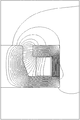
- FIG. 7 shows a magnetic field analysis result when the reactor DA having such a configuration obtains a low inductance in a large current range.
- iron powder compacts having magnetic characteristics indicated by solid lines in FIG. 6 were used for the core member 2A.
- FIG. 6 the magnetic characteristics of the grain-oriented electrical steel sheet are also shown by broken lines.
- FIG. 6 is a diagram showing the magnetic field-magnetic flux density characteristics of the core used in the reactor of the first embodiment.
- the horizontal axis in FIG. 6 is the magnetic field expressed in A / m units, and the vertical axis is the magnetic flux density expressed in T units.
- FIG. 7 is a diagram illustrating a state of the magnetic flux lines of the reactor in the first embodiment.
- many magnetic flux lines circulate in the core member 2A, and a part thereof flows out of the upper core member 21A and penetrates the coil 1A to the lower core member 22A. Inflow.
- the magnetic flux lines are substantially along the width direction of the conductor member of the coil 1A, and eddy currents generated by the magnetic flux lines are reduced.
- the reactor D is, for example, as shown in FIG. Inductance performance suitable for various applications can be obtained.
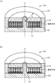
- FIG. 8 is a cross-sectional view showing the configuration of the reactor in the second embodiment.
- FIG. 9 is a diagram illustrating a state of the magnetic flux lines of the reactor in the second embodiment.
- FIG. 10 is a diagram showing a comparison between the magnetic flux lines of the reactor in the first embodiment and the magnetic flux lines of the reactor in the second embodiment.
- the other end portion of the second core portion is connected to the first core portion, and the first core portion extends from the peripheral portion that forms the opening portion to the first end.
- a protrusion that extends into the core is further provided.
- the reactor DB in the second embodiment includes a coil 1 ⁇ / b> A, a core member 2 ⁇ / b> B, and a gap member 3. Since the coil 1A and the gap member 3 in the reactor DB of the second embodiment are the same as the coil 1A and the gap member 3 in the reactor DA of the first embodiment, description thereof will be omitted.
- the core member 2B is formed of, for example, a magnetically (for example, magnetic permeability) isotropic material, and includes an upper core member 21B and a lower core member 22A. Since the lower core member 22A in the reactor DB of the second embodiment is the same as the lower core member 22A in the reactor DA of the first embodiment, the description thereof is omitted.
- the upper core member 21B has a polygonal shape having a predetermined thickness, for example, an upper end core member 21a of a hexagonal plate-like body, and an outer peripheral edge portion of the upper end core member 21a having a predetermined thickness. And a cylindrical side wall core member 21b extending in a substantially vertical direction, and an opening APA which is a through-opening is formed in the upper end core member 21a. Since the upper end core member 21a and the side wall core member 21b in the reactor DB of the second embodiment are the same as the upper end core member 21a and the side wall core member 21b in the reactor DA of the first embodiment, respectively. Is omitted.
- the upper core member 21B further includes a protrusion 21c that extends into the first core from the peripheral edge portion that forms the opening APA in the upper end core member 21a.
- the reactor DB according to the second embodiment having such a configuration, even when the reactor DB is designed to have a high inductance in a relatively small current range by increasing the number of turns of the coil 1A, as shown in FIG.
- the magnetic flux lines penetrating through the coil 1A can be brought close to a direction parallel to the axial direction of the coil 1A, and eddy current loss can be reduced for the reason described above. This can be easily understood with reference to FIG. 10 compared with the reactor DA in the first embodiment.
- the reactor DB in the second embodiment is parallel to the axial direction of the coil 1A due to the magnetic flux lines that penetrate the coil 1A when energized, as shown in FIG. Can be approached. For this reason, reactor DB in 2nd Embodiment can reduce an eddy current loss rather than the case where the protrusion part 21c is not provided.
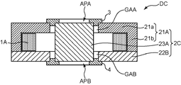
- FIG. 11 is a cross-sectional view showing the configuration of the reactor in the third embodiment.
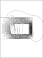
- FIG. 12 is a diagram illustrating a state of the magnetic flux lines of the reactor in the third embodiment.
- the other end portion of the second core portion is disposed in the second opening portion formed in the first core portion, and the peripheral surface of the other end portion and the periphery of the second opening portion.
- a second gap is provided between the surface and the surface.
- the reactor DC in the third embodiment includes a coil 1 ⁇ / b> A, a core member 2 ⁇ / b> C, and gap members 3 and 4. Since the coil 1A and the gap member 3 in the reactor DC of the third embodiment are the same as the coil 1A and the gap member 3 in the reactor DA of the first embodiment, description thereof will be omitted.
- the core member 2C is formed of, for example, a magnetically (for example, magnetic permeability) isotropic material, and includes an upper core member 21A, a lower core member 22B, and a core core member 23A. Since the upper core member 21A in the reactor DC of the third embodiment is the same as the upper core member 21A in the reactor DA of the first embodiment, the description thereof is omitted.
- the lower core member 22B is the same as the upper end core member 21a in the upper core member 21A, and is a plate-like body having the same polygonal shape as the upper end core member 21a, for example, a hexagonal shape.
- An opening APB which is a through-opening similar to the opening APA in 21a is formed.
- the opening APB is a circular hole having a diameter of a predetermined length centered on the center position (geometric gravity center position) of the lower core member 22B.
- the core part core member 23A is a cylindrical body having an outer diameter of a predetermined length similar to the convex piece core member 22b of the first embodiment.
- the core part core member 23A is solid but may be hollow, and a predetermined fluid such as air or water may be allowed to flow through the hollow part to improve the heat dissipation of the reactor.
- One end of the core core member 23A is inserted into the opening APA of the upper end core member 21a, and the peripheral surface (outer peripheral surface) at one end of the core core member 23A and the peripheral surface (inner periphery) of the opening APA.
- the first gap GAA is provided between the core portion 23A and the other end portion of the core portion core member 23A is inserted into the opening portion APB of the lower core member 22B.
- a second gap GAB is provided between the peripheral surface (outer peripheral surface) at the other end of the core member 23A and the peripheral surface (inner peripheral surface) of the opening APB, and the core member 23A is disposed in the
- the upper core member 21A and the lower core member 22B correspond to an example of the first core part including the coil 1A, and the core part core member 23A is the second core part arranged at the core part of the coil 1A. This corresponds to an example.
- the gap member 3 is a gap GAA formed at a predetermined interval (gap length) between a peripheral surface (outer peripheral surface) at one end of the core core member 23A and a peripheral surface (inner peripheral surface) of the opening APA. It is a member sandwiched between.
- the gap member 4 is a gap GAB formed at a predetermined interval (gap length) between the peripheral surface (outer peripheral surface) at the other end of the core core member 23A and the peripheral surface (inner peripheral surface) of the opening APB. It is a member sandwiched between.
- the gap member 3 maintains the gap length, and fixes the upper end core member 21a and the core core member 23A of the upper core member 21A, while the gap member 4 maintains the gap length, and The lower core member 22B and the core core member 23A are fixed.
- Each of the gap members 3 and 4 includes a donut-shaped cap portion in plan view and a cylindrical gap portion that is suspended from the lower surface of the cap portion and sandwiched between the gaps GA.
- a vertical cross section perpendicular to the circumferential direction of the gap members 3 and 4 is substantially T-shaped.
- Such gap members 3 and 4 are, for example, epoxy resin or alumina.
- the coil 1A is disposed in a space formed between the upper end core member 21a and the lower core member 22B and between the side wall core member 21b and the core core member 23A, and the core of the coil 1A.
- the core part core member 23A is arranged so as to penetrate the coil 1A.
- reactor DC in 3rd Embodiment of such a structure has the structure of several gap GA of 1st gap GAA and 2nd gap GAB, it is possible to arrange
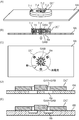
- FIG. 13 is a diagram illustrating a configuration of a reactor and an attachment member according to a modification of the third embodiment.
- FIG. 13A is an overall perspective view of the first aspect of the modified embodiment
- FIG. 13B is a cross-sectional view of the first aspect of the modified embodiment
- FIG. 13C is the modified embodiment. It is the bottom view seen from the attachment member side in the 1st mode of a form
- Drawing 13 (D) is a section schematic diagram showing the section in the 1st mode of the above-mentioned modification (scheme of Drawing 13 (C))
- FIG. 13E is a schematic cross-sectional view schematically showing a cross-section in the second mode of the modified embodiment.
- the reactor Normally, the reactor generates heat due to various losses, and when the temperature is increased, the reactor is formed of, for example, a heat-conductive metal material having a relatively low thermal conductivity for the purpose of heat transfer and heat dissipation. It is fixed in contact with the flat plate-shaped heat sink. Examples of the metal material include copper and its alloys, iron and its alloys, aluminum and its alloys, and the like.
- the reactor DC in the third embodiment is attached to a simple flat heat sink for the purpose of heat transfer and heat dissipation, the reactor DC has the second gap GAB, and the heat sink has electrical conductivity. Leakage magnetic flux leaking out due to the second gap GAB may cause an eddy current in the heat sink.
- the heat sink 6A in the first mode, as shown in FIGS. 13A to 13D, has a mounting surface on which the reactor DC ′ is mounted on the mounting surface of the coil 1A.
- One or a plurality of slit holes 6a penetrating the heat radiating plate 6A are formed while the longitudinal direction intersects with the second gap GAB in a plan view viewed from the axial direction.
- the plurality of slit holes 6a and 6b are arranged in the radial direction about the axis of the coil 1A so that the longitudinal direction intersects the second gap GAB. It is formed on a mounting surface to which the reactor DC ′ is mounted at a predetermined interval in the radial direction in the radial direction.
- the reactor DC ′ does not include the gap members 3 and 4 with respect to the reactor DC shown in FIG. 11, and radiates heat by the bolts 7 through the through holes formed in the core member 2C ′. Fastened to the plates 6A and 6B.
- the overall shape of the core member 2C ' is the same as that of the core member 2C, but the core member 2C' is composed of two members having the same shape at the top and bottom.
- the reactor DC ′ having such a configuration the slit hole 6a is formed in the heat radiating plate 6A, or the slit groove 6b is formed in the heat radiating plate 6B. It is blocked by 6a or slit groove 6b. Therefore, the reactor DC ′ having such a configuration can dissipate heat without causing power loss and inductance change.
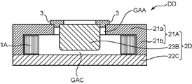
- FIG. 14 is a cross-sectional view showing the configuration of the reactor in the fourth embodiment.
- FIG. 15 is a diagram illustrating a state of the magnetic flux lines of the reactor in the fourth embodiment.
- the other end portion of the second core portion is disposed with a third gap between the other inner surface of the first core portion.
- the reactor DD in the fourth embodiment includes a coil 1 ⁇ / b> A, a core member 2 ⁇ / b> D, and a gap member 3. Since the coil 1A and the gap member 3 in the reactor DD of the fourth embodiment are the same as the coil 1A and the gap member 3 in the reactor DA of the first embodiment, description thereof will be omitted.
- the core member 2D is formed of, for example, a magnetically (for example, magnetic permeability) isotropic material, and includes an upper core member 21A, a lower core member 22C, and a core core member 23B. Since the upper core member 21A in the reactor DD of the fourth embodiment is the same as the upper core member 21A in the reactor DA of the first embodiment, the description thereof is omitted.
- the lower core member 22C is a plate-like body having a predetermined thickness and having the same polygonal shape as the outer shape of the upper end core member 21a, for example, a hexagonal shape.
- the core part core member 23B is a cylindrical body having an outer diameter with a predetermined length, similar to the convex piece core member 22b of the first embodiment.
- the core part core member 23B is solid but may be hollow, and a predetermined fluid such as air or water may be passed through the hollow part to improve the heat dissipation of the reactor.
- One end of the core part core member 23B is inserted into the opening APA of the upper end core member 21a, and the peripheral surface (outer peripheral surface) at one end of the core core member 23B and the peripheral surface (inner periphery) of the opening APA.
- a first gap GAA is provided between the core part 23B and the other end part of the core part core member 23B is provided between the inner face of the lower core member 22C and the third gap GAC. It is arranged with a gap.
- a gap member such as an epoxy resin or alumina is sandwiched between the third gap GAC.
- the peripheral edge portion at the other end of the core core member 23B may be chamfered by, for example, R chamfering or C chamfering. In the example shown in FIG. 14, the peripheral edge portion is rounded.
- the upper core member 21A and the lower core member 22C correspond to an example of the first core part including the coil 1A, and the core part core member 23B is the second core part arranged at the core part of the coil 1A. This corresponds to an example.
- the coil 1A is disposed in a space formed between the upper end core member 21a and the lower core member 22B and between the side wall core member 21b and the core core member 23B, and the core of the coil 1A.
- the core part core member 23B is disposed in the part.
- the reactor DD in the fourth embodiment having such a structure has a plurality of gaps GA of the first gap GAA and the third gap GAC, the gap GA can be divided and arranged.
- the reactor DC in the fourth embodiment having such a configuration can reduce the leakage magnetic flux to the outside as compared with the reactor DA in the first embodiment, as can be seen by comparing FIG. 7 and FIG. As a result, it is possible to minimize the influence of the leakage magnetic flux on the peripheral devices arranged around the reactor DD.
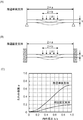
- FIG. 16 shows inductance characteristics of the reactors DA, DB, DC, DD in the first to fourth embodiments.
- the horizontal axis of FIG. 16 is a logarithmic scale and represents the current expressed in units of A, and the vertical axis represents the inductance expressed in units of ⁇ H.
- delta), and (circle) show each inductance characteristic of each reactor DA, DB, DC, and DD in 1st thru
- each of the reactors DA, DC, DD in the first, third and fourth embodiments has a relatively large current range, in the example shown in FIG. 16, in the range of about 20 A to about 200 A. Inductance fluctuation is small and stable. In particular, in the range of about 20A to about 150A, the inductance variation is less and more stable and preferable, and in the range of about 20A to about 100A, the inductance variation is even less and even more stable. More preferable.
- Each of the reactors DA, DC, DD in the first, third, and fourth embodiments is a large current type.
- the reactor DB in the second embodiment is stable with little variation in inductance in a relatively small current range, in the example shown in FIG. 16, in a range of about 5 A to about 25 A. In particular, in the range of about 5A to about 20A, the variation in inductance is smaller and more stable and preferable.
- FIG. 17 is a cross-sectional view showing the configuration of the reactor in the fifth embodiment.
- the coil 1A is a single coil having a pancake structure.
- the reactor DE in the fifth embodiment is the first to fourth embodiments.
- a coil 1B including a plurality of sub-coils stacked in the axial direction is used instead of the coil 1A.
- FIG. 17 shows the reactor DE of the fifth embodiment when the core member 2B in the reactor DB of the second embodiment is used. In the example shown in FIG.
- the reactor DE according to the fifth embodiment includes a coil 1 ⁇ / b> B, a core member 2 ⁇ / b> B, and a gap member 3. Since the core member 2B and the gap member 3 in the reactor DE of the fifth embodiment are the same as the core member 2B and the gap member 3 in the reactor DB of the second embodiment, description thereof will be omitted.
- the coil 1B includes a plurality of sub-coils stacked in the axial direction, and in the example shown in FIG. 17, two sub-coils 11a and 11b.
- Each of the subcoils 11a and 11b is formed by winding a strip-shaped conductor member so that the width direction of the conductor member is along the axial direction of the subcoils 11a and 11b (coil 1B), similarly to the coil 1A. .
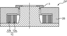
- FIG. 18 is a cross-sectional view showing the configuration of the reactor in the sixth embodiment.
- the coil 1A is a single coil having a pancake structure.
- the reactor DF in the sixth embodiment is the first to fourth embodiments.
- a coil 1C including a plurality of subcoils stacked in the radial direction is used instead of the coil 1A.
- FIG. 18 shows the reactor DF of the sixth embodiment when the core member 2B in the reactor DB of the second embodiment is used. In the example shown in FIG.
- the reactor DF in the sixth embodiment includes a coil 1 ⁇ / b> C, a core member 2 ⁇ / b> B, and a gap member 3. Since the core member 2B and the gap member 3 in the reactor DF of the sixth embodiment are the same as the core member 2B and the gap member 3 in the reactor DB of the second embodiment, description thereof will be omitted.
- the coil 1C includes a plurality of subcoils stacked in the radial direction, in the example shown in FIG. 18, two subcoils 12a and 12b.
- Each of the subcoils 12a and 12b is configured by winding a strip-shaped conductor member so that the width direction of the conductor member is along the axial direction of the subcoils 12a and 12b (coil 1C), similarly to the coil 1A.
- the subcoil 12a is disposed relatively inside, and the subcoil 12b is disposed relatively outside.
- FIG. 19 is a cross-sectional view showing the configuration of the reactor in the seventh embodiment.
- the coil 1A is a single coil having a pancake structure.
- the reactor DG in the seventh embodiment is the first to fourth embodiments.
- a coil 1D configured by laminating and winding a plurality of strip-shaped conductor members via an insulating layer is used instead of the coil 1A.
- FIG. 19 shows the reactor DG of the seventh embodiment when the core member 2B in the reactor DB of the second embodiment is used.
- the reactor DG in the seventh embodiment includes a coil 1 ⁇ / b> D, a core member 2 ⁇ / b> B, and a gap member 3. Since the core member 2B and the gap member 3 in the reactor DG of the seventh embodiment are the same as the core member 2B and the gap member 3 in the reactor DB of the second embodiment, description thereof will be omitted.
- the coil 1D is formed by winding a plurality of strip-shaped conductor members 13 so that the width direction of the plurality of conductor members 13 is along the axial direction of the coil 1D and is laminated in the radial direction via an insulating layer. It is composed by doing.
- each reactor DE, DF, and DG in the fifth to seventh embodiments includes a plurality of subcoils
- the connection of the plurality of subcoils is changed so that at least one of the plurality of subcoils is placed on the primary side.
- a coil can be used and at least one of the plurality of subcoils can be used as a secondary coil, so that it can be diverted to a transformer.
- Such transformers using the reactors DE, DF, and DG in the fifth to seventh embodiments can have a relatively large mutual inductance, low loss, and low noise.
- Such a transformer that diverts each reactor DE, DF, DG in the fifth to seventh embodiments can be used as a so-called insulating transformer, for example, as shown in an equivalent circuit in FIG. As shown in an equivalent circuit in FIGS. 20B and 20C, it can be used as a so-called choke transformer (filter).
- FIG. 20B shows the case of the common mode
- FIG. 20C shows the case of the differential mode.
- the thickness t of the conductor member is preferably equal to or less than the skin thickness with respect to the frequency in the AC power supplied to the reactors DA to DG.
- Reactors DA to DG having such a configuration can further reduce the eddy current loss.
- the current flowing through the coil flows only in the range up to the skin thickness ⁇ , and the current does not flow uniformly throughout the conductor cross section. Therefore, the eddy current loss can be reduced by setting the thickness t of the conductor member to the skin thickness ⁇ or less.
- the core members 2A to 2D are magnetically isotropic and formed of soft magnetic powder.
- the core members 2A to 2D are A ferrite core having magnetic isotropy may be used. Even with such a ferrite core, desired magnetic properties can be realized relatively easily and can be formed into a desired shape relatively easily.
- a reactor includes a coil, a first core portion including the coil, and a second core portion disposed at a core portion of the coil, and the coil includes a strip-shaped conductor member and the conductor.
- One of the inner surfaces of the first core part facing the one end of the coil in the axial direction and the coil in the axial direction are configured by winding so that the width direction of the member is along the axial direction of the coil
- the other inner surface of the first core portion facing the other end portion of the first core portion is parallel to at least one end portion of the coil and the other end portion of the coil, and is one end of the second core portion.
- the part is disposed in the opening formed in the first core part with a gap between the peripheral surface of the one end and the peripheral surface of the opening.
- the coil is configured by winding a strip-shaped conductor member such that the width direction of the conductor member is along the axial direction of the coil, and one of the coils in the axial direction is wound.
- the one inner surface of the first core portion facing the end portion and the other inner surface of the first core portion facing the other end portion of the coil in the axial direction are each of the one end portion and the other end portion of the coil. In the region covering at least the end portion, they are parallel. For this reason, in the said coil, since the width direction of a strip
- the reactor having such a configuration is a so-called pot-type reactor including a first core portion that encloses the coil, and the coil includes a second core portion at a core portion thereof, and thus has a relatively large inductance. be able to.
- the reactor having such a configuration is such that the one end portion of the second core portion is in the opening portion formed in the first core portion, and is between the peripheral surface of the one end portion and the peripheral surface of the opening portion. Therefore, by adjusting the gap distance (gap length), it is possible to control the variation in inductance in a desired current range.
- the gap length is equal to the diameter (inner diameter) of the opening portion and the one side. Since it is defined by the difference from the diameter (outer diameter) of the end, the reactor having such a configuration suppresses the variation in the gap length due to the deviation between the center of the opening and the center of the one end. Can do. For this reason, in the reactor having such a configuration, the product variation of the gap length (individual difference of reactors) is reduced. As a result, the reactor having such a configuration can also reduce the product variation of inductance.
- the electromagnetic attraction force and magnetostrictive expansion generated in the gap both occur in the radial direction.
- the reactor having such a configuration has high mechanical structural rigidity in the radial direction.
- the configured reactor can reduce vibration and noise. As a countermeasure against noise, even if noise occurs, even if the reactor is operated at a high frequency so that the frequency is higher than the audible band of, for example, about 18 kHz, the eddy current loss is reduced as described above. Therefore, loss can be reduced.
- the reactor having such a configuration can have a relatively large inductance, low loss, and low noise.
- the other end of the 2nd core part is connected with the 1st core part, and the 1st core part is a peripheral part which forms the opening. And a protrusion extending into the first core.
- a magnetic flux line penetrating the coil at the time of energization is curved in a reactor having a structure not provided with the protrusion, but in a reactor having such a configuration, Since the magnetic flux lines penetrating the coil during energization can be made closer to the direction parallel to the axial direction, the reactor having such a configuration can reduce eddy current loss as compared with the case where the protrusion is not provided. it can.
- the other end portion of the second core portion is disposed in a second opening formed in the first core portion, and the peripheral surface of the other end portion and the second end portion.
- a second gap is disposed between the opening and the peripheral surface of the opening.
- the reactor having such a configuration has a structure having a plurality of gaps (the first gap) and the second gap, the gaps can be divided and arranged. For this reason, the reactor having such a configuration can reduce the leakage magnetic flux to the outside, and as a result, the influence of the leakage magnetic flux on peripheral devices arranged around the reactor can be minimized.
- the above-described reactor further includes an attachment member for attaching the reactor, and the attachment member is formed of a material having electrical conductivity and thermal conductivity, and the reactor is attached to the reactor. And a slit hole penetrating the mounting member and a longitudinal direction intersecting the second gap in a plan view viewed from the axial direction of the coil. And a slit groove having a depth equal to or greater than the interval of the second gap.
- the mounting member has thermal conductivity, it is possible to dissipate heat generated in the reactor by the mounting member.
- the mounting member has electrical conductivity. Therefore, the leakage magnetic flux leaked due to the second gap may cause an eddy current in the mounting member.
- the reactor having the above-described configuration since the slit hole or the slit groove is formed in the attachment member, the eddy current is prevented from flowing. Therefore, such a reactor can radiate heat without causing power loss and inductance change.
- the other end portion of the second core portion is disposed with a third gap between the other inner surface of the first core portion.
- the reactor having such a configuration has a structure having a plurality of gaps (the first gap) and the third gap, so that the gaps can be divided and arranged. For this reason, the reactor having such a configuration can reduce the leakage magnetic flux to the outside, and as a result, the influence of the leakage magnetic flux on peripheral devices arranged around the reactor can be minimized.
- the coil has a ratio t / W of a radial thickness t to a width W of the conductor member of 1/10 or less.
- Such a reactor can further reduce the eddy current loss.
- the thickness t of the conductor member is equal to or less than a skin thickness with respect to a frequency in the AC power supplied to the reactor.
- Such a reactor can further reduce the eddy current loss.
- the first core portion is magnetically isotropic and forms a soft magnetic powder.
- the desired magnetic characteristics can be obtained relatively easily with respect to the first core portion, and can be formed into a desired shape relatively easily.
- the first core portion is a magnetically isotropic ferrite core.
- the desired magnetic characteristics can be obtained relatively easily with respect to the first core portion, and can be formed into a desired shape relatively easily.
- the above-described reactor further includes a heat conduction member filled in a gap generated between the coil and the first core portion.
- the gap is filled with the heat conductive member, and thus the reactor configured as described above conducts heat generated in the coil to the first core portion surrounding the coil via the heat conductive member. Can improve heat dissipation.
- the coil includes a plurality of subcoils and can be diverted to a transformer.
- This configuration can provide a transformer having the same structure as those of the above-described reactors.
- Such a transformer using any of the above reactors can have a relatively large mutual inductance, low loss, and low noise.
- the coil includes a plurality of subcoils, and the plurality of subcoils are stacked in the axial direction of the coils.
- This configuration can provide a reactor in which a plurality of subcoils are stacked in the axial direction.
- the coil includes a plurality of subcoils, and the plurality of subcoils are stacked in the radial direction of the coils.
- the coil in another aspect, in the above-described reactors, includes a plurality of strip-shaped conductor members, and an insulating layer is provided so that the width direction of the plurality of conductor members is along the axial direction of the coils. It is comprised by winding so that it may laminate
- a transformer having the same structure as the above-described reactor can be provided.
- Such a transformer using any of the above reactors can have a relatively large mutual inductance, low loss, and low noise.
- a reactor can be provided.
Landscapes
- Engineering & Computer Science (AREA)
- Power Engineering (AREA)
- Chemical & Material Sciences (AREA)
- Composite Materials (AREA)
- Microelectronics & Electronic Packaging (AREA)
- Coils Of Transformers For General Uses (AREA)
- Dc-Dc Converters (AREA)
- Coils Or Transformers For Communication (AREA)
Abstract
Description
図1は、第1実施形態におけるリアクトルの構成を示す図である。図1(A)は、コイル1Aの中心軸を含み、前記中心軸方向に沿って切断した縦断面図であり、図1(B)は、前記中心軸方向から平面視した場合における上面図である。図1(B)に示すAA線は、図1(A)の縦断面図における切断線である。図2は、第1実施形態のリアクトルのコイルを構成する導体部材において、その幅Wと厚さtとの関係を説明するための図である。図3は、コイルの巻線構造と渦電流損との関係を説明するための図である。図3(A)は、フラットワイズ巻線構造の場合を示し、図3(B)は、エッジワイズ巻線構造の場合を示す。図4は、コイルの巻線構造別の、リアクトルにおける周波数fと損失との関係を示すグラフである。図5は、第1実施形態におけるリアクトルの振動および騒音について説明するための図である。
図8は、第2実施形態におけるリアクトルの構成を示す断面図である。図9は、第2実施形態におけるリアクトルの磁束線の様子を示す図である。図10は、第1実施形態におけるリアクトルの磁束線と第2実施形態におけるリアクトルの磁束線とを対比して示す図である。
図11は、第3実施形態におけるリアクトルの構成を示す断面図である。図12は、第3実施形態におけるリアクトルの磁束線の様子を示す図である。
図14は、第4実施形態におけるリアクトルの構成を示す断面図である。図15は、第4実施形態におけるリアクトルの磁束線の様子を示す図である。
図17は、第5実施形態におけるリアクトルの構成を示す断面図である。第1ないし第4実施形態におけるリアクトルDA、DB、DC、DDでは、コイル1Aは、パンケーキ構造の単コイルであったが、第5実施形態におけるリアクトルDEは、これら第1ないし第4実施形態におけるリアクトルDA、DB、DC、DDにおいて、コイル1Aに代え、軸方向に積層された複数のサブコイルから成るコイル1Bを用いたものである。図17には、第2実施形態のリアクトルDBにおけるコア部材2Bを用いた場合における第5実施形態のリアクトルDEが示されている。この図17に示す例では、第5実施形態におけるリアクトルDEは、コイル1Bと、コア部材2Bと、ギャップ部材3とを備えて構成されている。これら第5実施形態のリアクトルDEにおけるコア部材2Bおよびギャップ部材3は、それそれ、第2実施形態のリアクトルDBにおけるコア部材2Bおよびギャップ部材3と同様であるので、その説明を省略する。
図18は、第6実施形態におけるリアクトルの構成を示す断面図である。第1ないし第4実施形態におけるリアクトルDA、DB、DC、DDでは、コイル1Aは、パンケーキ構造の単コイルであったが、第6実施形態におけるリアクトルDFは、これら第1ないし第4実施形態におけるリアクトルDA、DB、DC、DDにおいて、コイル1Aに代え、径方向に積層された複数のサブコイルから成るコイル1Cを用いたものである。図18には、第2実施形態のリアクトルDBにおけるコア部材2Bを用いた場合における第6実施形態のリアクトルDFが示されている。この図18に示す例では、第6実施形態におけるリアクトルDFは、コイル1Cと、コア部材2Bと、ギャップ部材3とを備えて構成されている。これら第6実施形態のリアクトルDFにおけるコア部材2Bおよびギャップ部材3は、それそれ、第2実施形態のリアクトルDBにおけるコア部材2Bおよびギャップ部材3と同様であるので、その説明を省略する。
図19は、第7実施形態におけるリアクトルの構成を示す断面図である。
Claims (14)
- コイルと、
前記コイルを内包する第1コア部と、
前記コイルの芯部に配置される第2コア部とを備え、
前記コイルは、帯状の導体部材を、該導体部材の幅方向が該コイルの軸方向に沿うように巻回することによって構成され、
前記軸方向における前記コイルの一方端部に対向する前記第1コア部の一方内面と前記軸方向における前記コイルの他方端部に対向する前記第1コア部の他方内面とは、前記コイルの一方端部および他方端部の各端部を少なくとも覆う領域では、平行であり、
前記第2コア部の一方端部は、前記第1コア部に形成された開口部内に、前記一方端部の周面と前記開口部の周面との間にギャップを空けて配置されていること
を特徴とするリアクトル。 - 前記第2コア部の他方端部は、前記第1コア部と連結されており、
前記第1コア部は、前記開口部を形成する周縁部から前記第1コア内へ延びる突起部をさらに備えること
を特徴とする請求項1に記載のリアクトル。 - 前記第2コア部の他方端部は、前記第1コア部に形成された第2開口部内に、前記他方端部の周面と前記第2開口部の周面との間に第2ギャップを空けて配置されていること
を特徴とする請求項1に記載のリアクトル。 - 当該リアクトルを取り付けるための取付部材をさらに備え、
前記取付部材は、電気伝導性を有するとともに熱伝導性を有する材料によって形成され、前記リアクトルが取り付けられる取付面に、前記コイルの軸方向から見た平面視にて、長手方向が前記第2ギャップと交差するとともに前記取付部材を貫通するスリット孔、または、長手方向が前記第2ギャップと交差するとともに前記第2ギャップの間隔以上の深さを有するスリット溝を備えること
を特徴とする請求項3に記載のリアクトル。 - 前記第2コア部の他方端部は、前記第1コア部の他方内面との間に第3ギャップを空けて配置されていること
を特徴とする請求項1に記載のリアクトル。 - 前記コイルは、前記導体部材の幅Wに対する径方向の厚さtの比t/Wが1/10以下であること
を特徴とする請求項1ないし請求項5のいずれか1項に記載のリアクトル。 - 前記コイルは、前記導体部材の前記厚さtが当該リアクトルに給電される交流電力における周波数に対する表皮厚み以下であること
を特徴とする請求項1ないし請求項5のいずれか1項に記載のリアクトル。 - 前記第1コア部は、磁気的に等方性を有し、軟磁性粉末を形成したものであること
を特徴とする請求項1ないし請求項5のいずれか1項に記載のリアクトル。 - 前記第1コア部は、磁気的に等方性を有するフェライトコアであること
を特徴とする請求項1ないし請求項5のいずれか1項に記載のリアクトル。 - 前記コイルと前記第1コア部との間に生じる間隙に充填される熱伝導部材をさらに備えること
を特徴とする請求項1ないし請求項5のいずれか1項に記載のリアクトル。 - 前記コイルは、複数のサブコイルから成り、トランスに転用可能な請求項1ないし請求項5のいずれか1項に記載のリアクトル。
- 前記コイルは、複数のサブコイルから成り、
前記複数のサブコイルは、前記コイルの軸方向に積層されること
を特徴とする請求項1ないし請求項5のいずれか1項に記載のリアクトル。 - 前記コイルは、複数のサブコイルから成り、
前記複数のサブコイルは、前記コイルの径方向に積層されていること
を特徴とする請求項1ないし請求項5のいずれか1項に記載のリアクトル。 - 前記コイルは、複数の帯状の導体部材を、該複数の導体部材の幅方向が該コイルの軸方向に沿うように、かつ、絶縁層を介して径方向に積層するように、巻回することによって構成されること
を特徴とする請求項1ないし請求項5のいずれか1項に記載のリアクトル。
Priority Applications (3)
| Application Number | Priority Date | Filing Date | Title |
|---|---|---|---|
| EP11809451.5A EP2597656A4 (en) | 2010-07-21 | 2011-07-20 | REACTOR |
| CN201180033322.0A CN102971813B (zh) | 2010-07-21 | 2011-07-20 | 电抗器 |
| KR1020137001424A KR101427542B1 (ko) | 2010-07-21 | 2011-07-20 | 리액터 |
Applications Claiming Priority (4)
| Application Number | Priority Date | Filing Date | Title |
|---|---|---|---|
| JP2010-163863 | 2010-07-21 | ||
| JP2010163863 | 2010-07-21 | ||
| JP2011-130858 | 2011-06-13 | ||
| JP2011130858A JP5662255B2 (ja) | 2010-07-21 | 2011-06-13 | リアクトル |
Publications (1)
| Publication Number | Publication Date |
|---|---|
| WO2012011276A1 true WO2012011276A1 (ja) | 2012-01-26 |
Family
ID=45496708
Family Applications (1)
| Application Number | Title | Priority Date | Filing Date |
|---|---|---|---|
| PCT/JP2011/004097 Ceased WO2012011276A1 (ja) | 2010-07-21 | 2011-07-20 | リアクトル |
Country Status (5)
| Country | Link |
|---|---|
| EP (1) | EP2597656A4 (ja) |
| JP (1) | JP5662255B2 (ja) |
| KR (1) | KR101427542B1 (ja) |
| CN (1) | CN102971813B (ja) |
| WO (1) | WO2012011276A1 (ja) |
Families Citing this family (10)
| Publication number | Priority date | Publication date | Assignee | Title |
|---|---|---|---|---|
| JP5622784B2 (ja) * | 2012-04-17 | 2014-11-12 | 株式会社タムラ製作所 | 磁性コア及びインダクタ |
| JP6160071B2 (ja) * | 2012-12-04 | 2017-07-12 | ミツミ電機株式会社 | インダクタ |
| JP2014225516A (ja) * | 2013-05-15 | 2014-12-04 | Necトーキン株式会社 | リアクトル |
| JP2015201542A (ja) * | 2014-04-08 | 2015-11-12 | 株式会社神戸製鋼所 | リアクトル |
| JP2015204406A (ja) * | 2014-04-15 | 2015-11-16 | 株式会社神戸製鋼所 | リアクトル |
| JP2016025218A (ja) * | 2014-07-22 | 2016-02-08 | パナソニックIpマネジメント株式会社 | コイル部品 |
| US11114232B2 (en) | 2017-09-12 | 2021-09-07 | Raycap IP Development Ltd | Inductor assemblies |
| WO2020189291A1 (ja) * | 2019-03-19 | 2020-09-24 | 三菱電機株式会社 | コイル装置および電力変換装置 |
| JP7182513B2 (ja) * | 2019-05-24 | 2022-12-02 | 株式会社Soken | 磁気部品及びこれを備えた電力変換装置 |
| WO2021180744A1 (en) * | 2020-03-11 | 2021-09-16 | Raycap, S.A. | Inductor assemblies and methods for forming the same |
Citations (10)
| Publication number | Priority date | Publication date | Assignee | Title |
|---|---|---|---|---|
| JPS59117120U (ja) * | 1983-01-27 | 1984-08-07 | 東洋電機製造株式会社 | 巻鉄心締付バンド |
| JPH03208317A (ja) * | 1990-01-10 | 1991-09-11 | Matsushita Electric Ind Co Ltd | コンバータトランス |
| JPH0626222U (ja) * | 1992-09-02 | 1994-04-08 | ミネベア株式会社 | 薄形コイル |
| JPH11345724A (ja) * | 1998-06-01 | 1999-12-14 | Matsushita Electric Ind Co Ltd | 磁気漏洩形高周波トランスとこれを使用するインバータ回路 |
| JP2000040626A (ja) * | 1998-07-24 | 2000-02-08 | Matsushita Electric Ind Co Ltd | チョークコイル |
| JP2001167939A (ja) * | 1999-12-09 | 2001-06-22 | Tokyo Coil Engineering Kk | ポットリベット型コア表面実装チョークコイル |
| JP2006032560A (ja) * | 2004-07-14 | 2006-02-02 | Tdk Corp | コイル部品 |
| JP2006310550A (ja) * | 2005-04-28 | 2006-11-09 | Tamura Seisakusho Co Ltd | ポットコアを使用したリアクトル及び、複合型リアクトル |
| JP2008021948A (ja) | 2006-07-14 | 2008-01-31 | Sumitomo Electric Ind Ltd | リアクトル用コア |
| JP2008186972A (ja) | 2007-01-30 | 2008-08-14 | Hitachi Metals Ltd | リアクトル磁心およびリアクトル |
Family Cites Families (5)
| Publication number | Priority date | Publication date | Assignee | Title |
|---|---|---|---|---|
| FR2422235A1 (fr) * | 1978-04-06 | 1979-11-02 | Telecommunications Sa | Nouveau circuit magnetique en ferrite et procede de reglage de ce circuit |
| JPS59117120A (ja) * | 1982-12-24 | 1984-07-06 | Hitachi Ltd | ウエハのプリアライメント装置 |
| JPS63193514A (ja) * | 1987-02-06 | 1988-08-10 | Matsushita Electric Works Ltd | 高周波コイル |
| JPH0626222A (ja) * | 1992-07-06 | 1994-02-01 | Kiyoshi Tanii | 二連二段式立体駐車装置 |
| JP3537635B2 (ja) * | 1997-05-28 | 2004-06-14 | 京セラ株式会社 | 巻線型インダクタ |
-
2011
- 2011-06-13 JP JP2011130858A patent/JP5662255B2/ja not_active Expired - Fee Related
- 2011-07-20 EP EP11809451.5A patent/EP2597656A4/en not_active Withdrawn
- 2011-07-20 CN CN201180033322.0A patent/CN102971813B/zh not_active Expired - Fee Related
- 2011-07-20 WO PCT/JP2011/004097 patent/WO2012011276A1/ja not_active Ceased
- 2011-07-20 KR KR1020137001424A patent/KR101427542B1/ko not_active Expired - Fee Related
Patent Citations (10)
| Publication number | Priority date | Publication date | Assignee | Title |
|---|---|---|---|---|
| JPS59117120U (ja) * | 1983-01-27 | 1984-08-07 | 東洋電機製造株式会社 | 巻鉄心締付バンド |
| JPH03208317A (ja) * | 1990-01-10 | 1991-09-11 | Matsushita Electric Ind Co Ltd | コンバータトランス |
| JPH0626222U (ja) * | 1992-09-02 | 1994-04-08 | ミネベア株式会社 | 薄形コイル |
| JPH11345724A (ja) * | 1998-06-01 | 1999-12-14 | Matsushita Electric Ind Co Ltd | 磁気漏洩形高周波トランスとこれを使用するインバータ回路 |
| JP2000040626A (ja) * | 1998-07-24 | 2000-02-08 | Matsushita Electric Ind Co Ltd | チョークコイル |
| JP2001167939A (ja) * | 1999-12-09 | 2001-06-22 | Tokyo Coil Engineering Kk | ポットリベット型コア表面実装チョークコイル |
| JP2006032560A (ja) * | 2004-07-14 | 2006-02-02 | Tdk Corp | コイル部品 |
| JP2006310550A (ja) * | 2005-04-28 | 2006-11-09 | Tamura Seisakusho Co Ltd | ポットコアを使用したリアクトル及び、複合型リアクトル |
| JP2008021948A (ja) | 2006-07-14 | 2008-01-31 | Sumitomo Electric Ind Ltd | リアクトル用コア |
| JP2008186972A (ja) | 2007-01-30 | 2008-08-14 | Hitachi Metals Ltd | リアクトル磁心およびリアクトル |
Non-Patent Citations (1)
| Title |
|---|
| See also references of EP2597656A4 * |
Also Published As
| Publication number | Publication date |
|---|---|
| EP2597656A4 (en) | 2015-06-17 |
| CN102971813A (zh) | 2013-03-13 |
| KR20130020841A (ko) | 2013-02-28 |
| CN102971813B (zh) | 2016-05-04 |
| JP2012044150A (ja) | 2012-03-01 |
| JP5662255B2 (ja) | 2015-01-28 |
| EP2597656A1 (en) | 2013-05-29 |
| KR101427542B1 (ko) | 2014-08-07 |
Similar Documents
| Publication | Publication Date | Title |
|---|---|---|
| JP5662255B2 (ja) | リアクトル | |
| KR101320170B1 (ko) | 리액터 | |
| CN103403817B (zh) | 电抗器及其设计方法 | |
| CN103608879B (zh) | 电抗器、变换器以及功率变换装置 | |
| US9412510B2 (en) | Three-phase reactor | |
| EP2584574B1 (en) | Reactor | |
| JP5307105B2 (ja) | 複合型巻線素子ならびにこれを用いた変圧器、変圧システムおよびノイズカットフィルタ用複合型巻線素子 | |
| KR20130014546A (ko) | 무선 전력 전송용 자기 소자 및 전력 공급 장치 | |
| US20140320249A1 (en) | Reactor | |
| JP5598372B2 (ja) | リアクトルおよびリアクトルの製造方法 | |
| JP2013219318A (ja) | リアクトル、コンバータ、および電力変換装置 | |
| JP2011124245A (ja) | リアクトル装置 | |
| JP2013157352A (ja) | コイル装置 | |
| WO2011145299A1 (ja) | リアクトル | |
| CN111316389B (zh) | 电抗器 | |
| JP5918020B2 (ja) | 非接触給電用コイル | |
| JP2015204406A (ja) | リアクトル | |
| JP5900741B2 (ja) | 複合磁心、リアクトルおよび電源装置 | |
| JP2015201542A (ja) | リアクトル | |
| WO2026018867A1 (ja) | コイル部品、コイル中間材、送電装置、受電装置及び電力伝送システム |
Legal Events
| Date | Code | Title | Description |
|---|---|---|---|
| WWE | Wipo information: entry into national phase |
Ref document number: 201180033322.0 Country of ref document: CN |
|
| 121 | Ep: the epo has been informed by wipo that ep was designated in this application |
Ref document number: 11809451 Country of ref document: EP Kind code of ref document: A1 |
|
| WWE | Wipo information: entry into national phase |
Ref document number: 2011809451 Country of ref document: EP |
|
| ENP | Entry into the national phase |
Ref document number: 20137001424 Country of ref document: KR Kind code of ref document: A |
|
| NENP | Non-entry into the national phase |
Ref country code: DE |