WO2012014302A1 - Dispositif d'affichage tête haute - Google Patents
Dispositif d'affichage tête haute Download PDFInfo
- Publication number
- WO2012014302A1 WO2012014302A1 PCT/JP2010/062785 JP2010062785W WO2012014302A1 WO 2012014302 A1 WO2012014302 A1 WO 2012014302A1 JP 2010062785 W JP2010062785 W JP 2010062785W WO 2012014302 A1 WO2012014302 A1 WO 2012014302A1
- Authority
- WO
- WIPO (PCT)
- Prior art keywords
- eyeball
- driver
- detection unit
- display
- position detection
- Prior art date
- Legal status (The legal status is an assumption and is not a legal conclusion. Google has not performed a legal analysis and makes no representation as to the accuracy of the status listed.)
- Ceased
Links
Images




Classifications
-
- G—PHYSICS
- G02—OPTICS
- G02B—OPTICAL ELEMENTS, SYSTEMS OR APPARATUS
- G02B27/00—Optical systems or apparatus not provided for by any of the groups G02B1/00 - G02B26/00, G02B30/00
- G02B27/01—Head-up displays
- G02B27/0101—Head-up displays characterised by optical features
-
- B—PERFORMING OPERATIONS; TRANSPORTING
- B60—VEHICLES IN GENERAL
- B60K—ARRANGEMENT OR MOUNTING OF PROPULSION UNITS OR OF TRANSMISSIONS IN VEHICLES; ARRANGEMENT OR MOUNTING OF PLURAL DIVERSE PRIME-MOVERS IN VEHICLES; AUXILIARY DRIVES FOR VEHICLES; INSTRUMENTATION OR DASHBOARDS FOR VEHICLES; ARRANGEMENTS IN CONNECTION WITH COOLING, AIR INTAKE, GAS EXHAUST OR FUEL SUPPLY OF PROPULSION UNITS IN VEHICLES
- B60K35/00—Instruments specially adapted for vehicles; Arrangement of instruments in or on vehicles
- B60K35/20—Output arrangements, i.e. from vehicle to user, associated with vehicle functions or specially adapted therefor
- B60K35/21—Output arrangements, i.e. from vehicle to user, associated with vehicle functions or specially adapted therefor using visual output, e.g. blinking lights or matrix displays
- B60K35/23—Head-up displays [HUD]
- B60K35/235—Head-up displays [HUD] with means for detecting the driver's gaze direction or eye points
-
- B—PERFORMING OPERATIONS; TRANSPORTING
- B60—VEHICLES IN GENERAL
- B60K—ARRANGEMENT OR MOUNTING OF PROPULSION UNITS OR OF TRANSMISSIONS IN VEHICLES; ARRANGEMENT OR MOUNTING OF PLURAL DIVERSE PRIME-MOVERS IN VEHICLES; AUXILIARY DRIVES FOR VEHICLES; INSTRUMENTATION OR DASHBOARDS FOR VEHICLES; ARRANGEMENTS IN CONNECTION WITH COOLING, AIR INTAKE, GAS EXHAUST OR FUEL SUPPLY OF PROPULSION UNITS IN VEHICLES
- B60K37/00—Dashboards
- B60K37/20—Dashboard panels
-
- G—PHYSICS
- G02—OPTICS
- G02B—OPTICAL ELEMENTS, SYSTEMS OR APPARATUS
- G02B27/00—Optical systems or apparatus not provided for by any of the groups G02B1/00 - G02B26/00, G02B30/00
- G02B27/0093—Optical systems or apparatus not provided for by any of the groups G02B1/00 - G02B26/00, G02B30/00 with means for monitoring data relating to the user, e.g. head-tracking, eye-tracking
-
- B—PERFORMING OPERATIONS; TRANSPORTING
- B60—VEHICLES IN GENERAL
- B60K—ARRANGEMENT OR MOUNTING OF PROPULSION UNITS OR OF TRANSMISSIONS IN VEHICLES; ARRANGEMENT OR MOUNTING OF PLURAL DIVERSE PRIME-MOVERS IN VEHICLES; AUXILIARY DRIVES FOR VEHICLES; INSTRUMENTATION OR DASHBOARDS FOR VEHICLES; ARRANGEMENTS IN CONNECTION WITH COOLING, AIR INTAKE, GAS EXHAUST OR FUEL SUPPLY OF PROPULSION UNITS IN VEHICLES
- B60K2360/00—Indexing scheme associated with groups B60K35/00 or B60K37/00 relating to details of instruments or dashboards
- B60K2360/20—Optical features of instruments
- B60K2360/33—Illumination features
- B60K2360/334—Projection means
-
- B—PERFORMING OPERATIONS; TRANSPORTING
- B60—VEHICLES IN GENERAL
- B60K—ARRANGEMENT OR MOUNTING OF PROPULSION UNITS OR OF TRANSMISSIONS IN VEHICLES; ARRANGEMENT OR MOUNTING OF PLURAL DIVERSE PRIME-MOVERS IN VEHICLES; AUXILIARY DRIVES FOR VEHICLES; INSTRUMENTATION OR DASHBOARDS FOR VEHICLES; ARRANGEMENTS IN CONNECTION WITH COOLING, AIR INTAKE, GAS EXHAUST OR FUEL SUPPLY OF PROPULSION UNITS IN VEHICLES
- B60K35/00—Instruments specially adapted for vehicles; Arrangement of instruments in or on vehicles
- B60K35/60—Instruments characterised by their location or relative disposition in or on vehicles
Definitions
- the present invention relates to a head-up display device, and more particularly to a head-up display device that adjusts a position for displaying an image in the driver's field of view in accordance with the position of the driver's eyeball.
- Patent Document 1 discloses a head-up display device that detects the position of the driver's eyeball with a camera.
- the position of the driver's eyeball is detected by a CCD camera installed in the housing of the head-up display device, and the combined position of the display image is adjusted according to the detected position of the eyeball.
- the CCD camera for detecting the position of the driver's eyeball is installed in a narrow housing of the head-up display device.
- the CCD camera in the housing detects the position of the driver's eyeball by capturing an image of the driver's face projected on the windshield.
- the reflectance of the windshield is low and the light outside the vehicle passing through the windshield is strong, the contrast of the image of the driver's face projected on the windshield is low. Therefore, it is very difficult to detect the position of the eyeball from the housing with a CCD camera. For this reason, the above-described technique cannot be realized as an actual apparatus, and improvement is desired.
- the present invention has been made in view of such circumstances, and its purpose is to move an image to an appropriate position even if the position of the driver's eyeball fluctuates depending on the posture of the driver.
- Another object of the present invention is to provide a head-up display device capable of preventing an image to be displayed from being blocked from a driver's view.
- the present invention includes a display unit that displays an image using light rays in the field of view of the driver of the host vehicle, and an eyeball position detection unit that detects the position of the eyeball of the driver of the host vehicle.
- the position for displaying the image is adjusted according to the position of the eyeball of the driver of the own vehicle detected by the unit, so that the eyeball position detection unit does not overlap the optical axis of the light beam for displaying the image.
- the display unit that displays an image by light rays in the field of view of the driver of the host vehicle is a position that displays the image according to the position of the driver's eyeball detected by the eyeball position detection unit. Adjust. Therefore, even when the position of the driver's eyeball fluctuates depending on the driver's posture or the like, the video can be moved to an appropriate position.
- the eyeball position detection unit is arranged so that the display unit does not overlap with the optical axis of the light beam for displaying an image. Therefore, the image displayed by the display unit is less likely to be blocked from the driver's view by the eyeball position detection unit.
- the “optical axis” in the invention of the present application means a virtual light beam that passes through the center most among light beams (light beams) for the display unit to display an image.
- the present invention is provided on a display unit for displaying an image with light rays in the field of view of the driver of the own vehicle and an instrument panel of the own vehicle, and detects the position of the eyeball of the driver of the own vehicle.
- An eyeball position detection unit, and the display unit adjusts a position for displaying an image according to the position of the driver's eyeball detected by the eyeball position detection unit.
- This is a head-up display device arranged so as not to overlap with the optical axis of a light beam for displaying an image.
- the display unit that displays an image by light rays in the field of view of the driver of the host vehicle is a position that displays the image according to the position of the driver's eyeball detected by the eyeball position detection unit. Adjust. Therefore, even when the position of the driver's eyeball fluctuates depending on the driver's posture or the like, the video can be moved to an appropriate position.
- the eyeball position detection unit is arranged so that the display unit does not overlap with the optical axis of the light beam for displaying an image. Therefore, the image displayed by the display unit is less likely to be blocked from the driver's view by the eyeball position detection unit.
- the eyeball position detection unit is provided on the surface of the instrument panel of the host vehicle. Therefore, the eyeball position detection unit can be disposed in the vicinity of the optical axis of the light beam for the display unit to display an image. Since the eyeball position detection unit is disposed in the vicinity of the optical axis, the influence of an error in detecting the position of the eyeball due to a shift between the position of the eyeball position detection unit and the optical axis is reduced. Moreover, it becomes easy to arrange
- the “surface of the instool panel” means, for example, the upper surface of the dashboard, the front of the dashboard (passenger seat side), the surface of the instrument panel equipped with the instruments, and the instruments. It means the edge of the light shielding plate that covers the upper part of the instrument panel that is being used and the surface of the top plate that covers the upper part of the instrument panel that is equipped with the instruments.
- the present invention also provides a display unit for displaying an image by light within the field of view of the driver of the host vehicle, and an eyeball position detection unit for detecting the position of the driver's eyeball provided on the steering column of the host vehicle.
- the display unit adjusts the position for displaying the image according to the position of the eyeball of the driver of the own vehicle detected by the eyeball position detection unit, and the eyeball position detection unit displays the image by the display unit.
- the head-up display device is arranged so as not to overlap the optical axis of the light beam.
- the display unit that displays an image by light rays in the field of view of the driver of the host vehicle is a position that displays the image according to the position of the driver's eyeball detected by the eyeball position detection unit. Adjust. Therefore, even when the position of the driver's eyeball fluctuates depending on the driver's posture or the like, the video can be moved to an appropriate position.
- the eyeball position detection unit is arranged so that the display unit does not overlap with the optical axis of the light beam for displaying an image. Therefore, the image displayed by the display unit is less likely to be blocked from the driver's view by the eyeball position detection unit.
- the present invention is also provided with a display unit for displaying an image by light rays in the field of view of the driver of the host vehicle, and on the inner surface of either the left or right side of the cabin of the host vehicle, and the position of the eyeball of the driver of the host vehicle
- a display unit that adjusts a position for displaying an image in accordance with the position of the eyeball of the driver of the host vehicle detected by the eyeball position detection unit, and the eyeball position detection unit includes: This is a head-up display device in which the display unit is arranged so as not to overlap the optical axis of the light beam for displaying an image.
- the display unit that displays an image by light rays in the field of view of the driver of the host vehicle is a position that displays the image according to the position of the driver's eyeball detected by the eyeball position detection unit. Adjust. Therefore, even when the position of the driver's eyeball fluctuates depending on the driver's posture or the like, the video can be moved to an appropriate position.
- the eyeball position detection unit is arranged so that the display unit does not overlap with the optical axis of the light beam for displaying an image. Therefore, the image displayed by the display unit is less likely to be blocked from the driver's view by the eyeball position detection unit.
- the eyeball position detection unit is provided on either the left or right inner surface of the passenger compartment of the host vehicle. Therefore, it becomes easy to accurately detect the position of the driver's eyeball in the vehicle front-rear direction and the vehicle vertical direction in a side view. Further, it can be assumed that the position of the driver's eyeball is on a line parallel to the front-rear direction of the host vehicle passing through the center of the driver seat. Therefore, if the position of the eyeball position detection unit can detect the position of the driver's eyeball in the vehicle front-rear direction and the vehicle vertical direction by side view, information for specifying the position of the driver's eyeball is obtained. It becomes possible. Therefore, the position of the eyeball in the three-dimensional space can be detected with high accuracy.
- the display range in which the display unit displays the video can be set within the visible range in which the driver of the host vehicle can visually recognize the entire displayed video.
- the position of the eyeball of the driver of the own vehicle detected by the eyeball position detection unit is set. Based on this, the display range in which the display unit displays the video is set within the visible range where the driver of the host vehicle can visually recognize the entire displayed video. Therefore, even if the error included in the position of the eyeball of the driver of the host vehicle detected by the eyeball position detection unit is maximum, the entire displayed image is within the visible range that the driver can visually recognize. . Therefore, it is possible to make the video displayed on the driver surely visible.
- the light passing range for the display unit to display an image can be arranged so as not to overlap the eyeball position detection unit.
- the light passing range for the display unit to display an image is arranged so as not to overlap the eyeball position detection unit. Therefore, the image displayed by the display unit can be prevented from being blocked from the driver's view by the eyeball position detection unit.
- the light beam passing range is arranged so as to overlap with the eyeball position detection unit, and the display unit has an eyeball position detection unit in the vicinity of the optical axis of the light beam for displaying an image. It is possible to arrange. Therefore, it becomes easy to accurately detect the position of the driver's eyeball from the left and right angles and the vertical angle when the driver's eyeball is viewed from the eyeball position detection unit.
- the display unit may be arranged so that the end of the light beam passage range for displaying an image does not overlap the eyeball position detection unit.
- the display unit is arranged so that the end of the light beam passage range for displaying an image does not overlap the eyeball position detection unit. Therefore, the image displayed by the display unit can be prevented from being blocked from the driver's view by the eyeball position detection unit.
- the display unit displays a display range in which the display unit displays an image based on the position of the driver's eyeball detected by the eyeball position detection unit within a range where the driver's eyeball is located.
- the entire displayed image can be adjusted based on the visible range that the driver of the host vehicle can visually recognize.
- the display unit displays an image based on the position of the driver's eyeball detected by the eyeball position detection unit within the range where the driver's eyeball is located.
- the display range is adjusted based on the visible range in which the driver of the host vehicle can visually recognize the entire displayed video. For this reason, within the range where the eyeball of the driver of the own vehicle is located, the display range for displaying the image is changed according to the viewable range where the driver of the own vehicle can visually recognize the entire displayed image. Is possible.
- the eyeball position detection unit detects a horizontal deviation angle and a vertical deviation angle of the position of the driver's eyeball viewed from the eyeball position detection unit, thereby detecting the eyeball of the driver of the host vehicle.
- the position can be detected.
- the eyeball position detection unit detects the driving angle of the host vehicle by detecting the horizontal deflection angle and the vertical deflection angle of the driver's eyeball position viewed from the eyeball position detection unit. The position of the person's eyeball is detected. For this reason, since the eyeball position detection unit does not need to detect the distance from the driver's eyeball, the position of the driver's eyeball can be easily detected by a camera or the like.
- the eyeball position detection unit includes the distance to the driver's eyeball, the position of the driver's seat of the host vehicle, the tilt angle of the backrest of the driver's seat, the tilt angle of the steering column of the host vehicle, and the steering of the host vehicle.
- the detected position of the eyeball of the driver of the host vehicle can be corrected based on any detected value of the wheel position.
- the eyeball position detection unit includes the distance to the driver's eyeball, the position of the driver's seat of the own vehicle, the inclination angle of the backrest of the driver's seat, the inclination angle of the steering column of the own vehicle, and the Based on one of the detected values of the position of the steering wheel, the detected position of the eyeball of the driver of the own vehicle is corrected. For this reason, the eyeball position detection unit can detect the position of the driver's eyeball with higher accuracy.
- the eyeball position detection unit is provided in the steering column of the host vehicle, and the eyeball position detection unit cannot be disposed in the vicinity of the optical axis of the light beam for displaying an image. Even when the influence of the error in detecting the position of the eyeball due to the shift between the position and the optical axis is large, the error can be reduced by referring to information such as the tilt angle of the steering column of the host vehicle.
- the display unit can change the position for displaying an image when the amount of change in the position of the eyeball of the driver of the host vehicle detected by the eyeball position detection unit exceeds a predetermined threshold.
- the display unit changes the position for displaying an image when the amount of change in the position of the driver's eyeball detected by the eyeball position detection unit exceeds a predetermined threshold. Therefore, when the change amount of the position of the driver's eyeball is equal to or less than the threshold value, the video is stably displayed at the same position, so that hunting or the like can be prevented. Further, when the amount of change in the position of the driver's eyeball exceeds the threshold, an image can be displayed at a position corresponding to the position of the eyeball.
- the display unit has a shortest distance between the end of the display range where the image is displayed and the end of the viewable range within the viewable range where the driver of the vehicle can see the entire displayed image.
- the distance is less than a predetermined threshold, the position where the video is displayed can be changed.
- the display unit is within the viewable range where the driver of the host vehicle can visually recognize the entire displayed image, and the end of the display range where the image is displayed and the end of the viewable range.
- the position for displaying the video is changed.
- the amount of change in the position of the driver's eyeball is small and the image display range is within the viewable range, the image is stably displayed at the same position, thus preventing hunting and the like. it can.
- the amount of change in the position of the driver's eyeball is large, the distance between the end of the display range and the end of the viewable range is shortened, and the image display range is likely to deviate from within the viewable range.
- the video is displayed at a position corresponding to the position of the eyeball, it is possible to fit the video display range within the visible range.
- the head-up display device of the present invention even if the position of the driver's eyeball fluctuates due to the driver's posture or the like, the displayed image is displayed in the driver's field of view while moving the image to an appropriate position. It can be prevented from being shielded from.
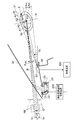
- a head-up display device 10a according to the first embodiment of the present invention shown in FIG. 1 is a general automobile including a front windshield 30, an instrument panel 40, a driver seat 60, a steering wheel 70, and a steering column 80. Installed in the passenger compartment.
- the head-up display device 10 a includes a head-up display (HUD) image display unit 20 inside the instrument panel 40.
- the HUD image display unit 20 projects display light for displaying a display image from the upper part of the instrument panel 40 toward the front windshield 30.
- the display light having the optical axis R reflected by the surface of the front windshield 30 on the vehicle interior side reaches the position of the driver's eyeball. The driver can visually recognize the display image I in the driver's field of view outside the front windshield 30.
- the HUD image display unit 20 includes a HUD image display 21, an image position adjusting concave mirror 22, and an opening garnish 23.
- the HUD image display 21 is for emitting a light beam for displaying the display image I.
- the image position adjusting concave mirror 22 is for adjusting the position at which the display image I is displayed outside the front windshield 30 by changing the angle of the concave mirror.
- the opening garnish 23 is a member for decorating the opening of the light beam reflected by the image position adjusting concave mirror 22.
- an eyeball position detection unit 50 for detecting the position of the driver's eyeball is installed on the upper part of the instrument panel 40.
- the eyeball position detection unit 50 is mounted on a conventional vehicle and has a configuration similar to that of a device for detecting closed eyes due to a driver's sleep.
- the eyeball position detection unit 50 is configured integrally with an infrared irradiation LED that irradiates near infrared auxiliary light and an infrared imaging element that is a near infrared camera in consideration of night use.
- a processing device 100 and an image position adjusting drive device 200 are provided inside the instrument panel 40.
- the processing device 100 processes the image of the driver's face imaged by the eyeball position detection unit 50, and the elevation angle obtained by viewing the driver's eyeball position EP from the eyeball position detection unit 50 by a method such as pattern matching or filtering. Identifies as a horizontal angle. Further, as will be described later, the processing apparatus 100 determines an ideal position ID of the display image I based on the detected eyeball position EP. Further, the processing device 100 sends a control signal for displaying the display image I at the ideal position to the image position adjusting drive device 200.
- the image position adjusting drive device 200 adjusts the angle of the image position adjusting concave mirror 22 of the HUD image display unit 20 based on a control signal from the processing device 100.
- the position of the eyeball of the driver who observes the display image I of the HUD image display unit 20 is normally distributed in a range EA that is an ellipse in a side view as shown in FIG.
- An inner oval range EA 95 shown in FIG. 2 is a range in which the eyeball positions EP of many people (for example, 95% of people) are distributed.
- an outer elliptical area EA 99 shown in FIG. 2 is an area in which the eyeball positions EP of most people (for example, 99%) are distributed. Due to the extremely special driving posture and physique, all the indicators in the passenger compartment are visible so that it can be seen from the eyeball positions of most people, for example 99%, except for the eyeball positions EP outside these ranges EA 95 and EA 99.
- the range EA is not limited to the above ranges EA 95 and EA 99, and can be set to various arbitrary values.
- the eyeballs are distributed in the outer elliptical range rather than the inner elliptical range. What is necessary is just to set so that there may be many positions EP.
- the head-up display in which a sufficient distance is ensured between the display image I and the driver's eyeball is limited in the range in which the driver can visually recognize the angle within a very narrow range. Therefore, if the display position of the display image I remains fixed, it cannot be designed to cover the range EA where the driver's eyeball exists. Therefore, in the conventional head-up display device, it is necessary to manually adjust the vertical position of the display image I to a position where the driver can visually recognize his / her own eyeball position.
- Patent Document 1 a technique for automatically adjusting the display position of the display image I has been proposed as in the above-mentioned Patent Document 1 and the like.
- Is two-dimensional information such as a horizontal deflection angle and a vertical deflection angle of the eyeball position. It is also possible to acquire three-dimensional information including the distance from the eyeball position by measuring the distance by adjusting the focal length of the camera.
- the distance measurement by adjusting the focal length of the camera is generally low in accuracy, and in order to adjust the display position of the display image I, it is not sufficient to directly use the three-dimensional information thus obtained.
- the eyeball position detection unit 50 automatically detects the eyeball position EP of the driver at a low cost and with high accuracy using a practically established realistic detection means. Then, the HUD image display unit 20 automatically moves the display image I to a position optimal for the eyeball position EP. This realizes the head-up display device 10a that can be visually recognized in any physique and driving posture (excluding an extreme posture inappropriate for driving).
- the ideal position ID of the display image I of the head-up display at this time is a viewable range that is not shielded by the visual field constraint RE on the structure such as the opening in the upper part of the instrument panel 40 or the structure inside the HUD image display unit 20.
- the middle of V is a viewable range that is not shielded by the visual field constraint RE on the structure such as the opening in the upper part of the instrument panel 40 or the structure inside the HUD image display unit 20.
- the middle of V When the eyeball position EP is at the center of the range EA 99 , the eyeball position detection unit 50 detects an image of the driver's eyeball at a predetermined elevation angle.
- a general eyeball position EP will be considered. From eye position detection unit 50, the eye position EP of the eye to be present in a range EA within 99, between the upper tangent line U and the lower tangent line L in the range EA 99, is detected at a position of a predetermined elevation angle.
- the points An, A0, A1, A2, A3, and Af on the straight line A are observed from the eyeball position detection unit 50 with the same elevation angle ⁇ a.
- the eyeball position detection unit 50 is disposed in the vicinity of the optical axis R at a position that does not overlap the optical axis R. For this reason, there is no significant difference between the elevation angle of the eyeball position EP viewed from the eyeball position detection unit 50 and the elevation angle of the optical axis R connecting the ideal position ID, which is the display position of the display image I, to the eyeball position EP.
- a straight normal H connecting the eyeball position detection unit 50 and the center of the range EA 99 is assumed.
- a point A0 that is an intersection of the normal line H and the straight line A is set as a representative point of a group of points An to Af on the straight line A.
- the position of the display image I is controlled at a position corresponding to the representative point A0. That is, in the present embodiment, as the eyeball position EP, the control of the display position of the display image I with respect to the points An to Af at which the elevation angle ⁇ a from the eyeball position detection unit 50 is observed is performed as follows. Regardless of the position between Af, the eyeball position EP in the space is controlled to exist at the point A0.
- the distance between the upper end portion R 0 of the drawing range of the display image I and the visible range upper limit Va when the display image I is controlled to the optimum position with respect to the point A 0 that is the eyeball position EP is a distance D. .
- the display position of the display image I is controlled based on the representative point A0.
- the Af point position of the display image I within the visible range V from the eyeball position EP is highest observed when the distance between the visible range upper limit Va and upper portion R Af drawing range as a distance C, the distance
- the display image I is always visible.
- the margin usually provided in accordance with the above-described vehicle vibration or the like is reduced from the distance D to (distance D ⁇ distance C). Therefore, by designing (distance D ⁇ distance C) to be a margin necessary for preventing an image from being lost during temporary movement of the eyeball due to vibration or the like, at the point Af where the margin becomes the smallest. Also, good visibility of the image is ensured. The same applies to the point An and the visible range lower limit Vb. In this way, the appropriate display range P of the display image I is determined.
- the eyeball position detection unit 50 is brought close to the optical axis R of the light beam for displaying the display image I, and the visible range V, the drawing range of the display image I, the optical axis R and the eyeball position detection unit. 50 is designed so that the display image I can be visually recognized with an appropriate margin from two points An and Af, which are the end points of the range EA 99 where the eyeball position EP exists.
- the HUD image display unit 20 that displays the display image I with light rays in the field of view of the driver of the host vehicle is displayed according to the eyeball position EP of the driver of the host vehicle detected by the eyeball position detection unit 50.
- the position where the image I is displayed is adjusted. Therefore, even if the eyeball position EP fluctuates depending on the driver's posture or the like, the display image I can be displayed at an appropriate position.
- the eyeball position detection unit 50 is arranged so that the HUD image display unit 20 does not overlap the optical axis R of the light beam for displaying the display image I. Therefore, the eyeball position detection unit 50 can prevent the display image I displayed by the HUD image display unit 20 from being blocked from the driver's view.
- the eyeball position detection unit 50 is provided on the surface of the instrument panel 40 of the host vehicle. Therefore, the eyeball position detection unit 50 can be disposed near the optical axis R. Since the eyeball position detection unit 50 is disposed in the vicinity of the optical axis R, the influence of an error in detecting the eyeball position EP due to a deviation between the position of the eyeball position detection unit 50 and the optical axis R is reduced. Moreover, it becomes easy to arrange
- the light beam passing range for the HUD image display unit 20 to display the display image I does not overlap the eyeball position detection unit 50 in a side view of the host vehicle. Has been placed. Therefore, the eyeball position detection unit 50 can prevent the display image I displayed by the display unit from being blocked from the driver's view.
- the light beam passing range is arranged so as to overlap the eyeball position detection unit 50, and the HUD image display unit 20 is positioned on the optical axis R of the light beam for displaying the display image I. It is possible to arrange the eyeball position detection unit 50 in the vicinity. Therefore, it becomes easy to accurately detect the driver's eyeball position EP from the left and right and vertical angles when the driver's eyeball is viewed from the eyeball position detection unit 50.
- the HUD image display unit 20 is arranged so that the end of the light beam passage range for displaying the display image I does not overlap the eyeball position detection unit 50. Therefore, the eyeball position detection unit 50 can prevent the display image I displayed by the HUD image display unit 20 from being blocked from the driver's view.
- the driver monitor camera is usually provided at a position where the target driver's face such as the upper part of the steering column 80 can be appropriately observed.
- the eyeball position detection unit 50 having a configuration similar to that of the driver monitor camera is moved to a position relatively close to the optical axis R on the upper part of the instrument panel 40.
- the eyeball position detection unit 50 can be brought close to the optical axis R, the eyeball position detection unit 50 interferes with the visual field of the driver and cannot be completely matched.
- the optical axis R and the eyeball position detection unit 50 are brought close to each other, the display image I can be visually recognized even in control using only the driver's eyeball position EP detected by the image recognition function of the driver monitor camera. Can be maintained within a certain range.
- HUD image display unit 20 in the range EA 99 eyeball of the driver of the vehicle is positioned, HUD image display unit 20 based on the eye position EP of the eyeball position detection unit 50 has detected the The display range for displaying the display image I is adjusted based on the viewable range V in which the driver can visually recognize the entire display image I. For this reason, within the range EA 99 where the driver's eyeball is located, the display range in which the display image I is displayed according to the viewable range V where the driver can visually recognize the entire display image I displayed. Can be changed.
- the HUD image display unit 20 displays based on the eyeball position EP detected by the eyeball position detection unit 50.
- the display range for displaying the image I is set to be within the visible range V where the driver of the host vehicle can visually recognize the entire display image I. Therefore, even if the error included in the eyeball position EP detected by the eyeball position detection unit 50 is maximum, the entire display image I is within the visible range V that can be visually recognized by the driver. Therefore, it is possible to make the video displayed on the driver surely visible.
- the head-up display device 10a that automatically adjusts the display position of the display image I to a position that is always visible is not an auxiliary device for the instruments, and is mounted on the vehicle by replacing the functions of the instruments. May be possible. Further, the head-up display device 10a of the present embodiment can be used for emergency and important displays such as a collision warning that must be visible. As a result, the value of the head-up display can be dramatically increased.
- the eyeball position detection unit 50 detects the horizontal deviation angle and the vertical deviation angle of the eyeball position EP of the driver of the host vehicle viewed from the eyeball position detection unit 50.
- the eyeball position EP is detected. For this reason, since the eyeball position detection unit 50 does not need to detect the distance from the driver's eyeball using only two-dimensional information, the eyeball position EP of the driver can be easily detected by a camera or the like.
- the installation position of the eyeball position detection unit 50 can be other than the upper surface of the instrument panel 40.
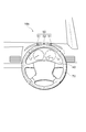
- the installation position of the eyeball position detection unit 50 is defined as the corner between the upper surface of the instrument panel 40 and the surface on which the instruments are arranged. Also good.
- several infrared irradiation LEDs 51 and one infrared imaging element 52 constituting the eyeball position detection unit 50 are arranged at the corners. Thereby, the eyeball position detection unit 50 can be efficiently arranged in a small area.
- the eyeball position detection unit 50 is arranged on the upper surface of the instrument panel 40 of the vehicle and the eyeball position detection unit 50 is arranged in the vicinity of the optical axis R, so that the angle deviation ⁇ gap is reduced.
- the impact can be reduced.
- the eyeball position detection unit 50 cannot be disposed on the upper surface of the instrument panel 40 of the vehicle.
- the eyeball position detection unit 50 must be disposed at a distant position. In such a case, the influence of the angle deviation ⁇ gap is increased, and the detection accuracy of the eyeball position EP may deteriorate. For this reason, it may be impossible to keep the display position of the display image I within a range that is always visible from the driver with an appropriate margin.
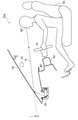
- the eyeball position detection unit 50 is installed on the steering column 80, which is one of the installation positions of typical existing driver monitor cameras.
- the alternative means shown in FIG. The elevation angle ⁇ x of the eyeball position EP is detected from the image information of the camera of the eyeball position detection unit 50 on the steering column 80.
- the camera mounting angle of the eyeball position detection unit 50 is not horizontal, and the tilt angle ⁇ w of the steering column 80 can be changed by a tilt mechanism. Therefore, the elevation angle ⁇ x is an angle when the eyeball position EP is observed with respect to the horizontal plane by taking into account the inclination angle ⁇ w of the steering column 80 acquired by the camera mounting angle of the eyeball position detection unit 50, the sensor, or the like. .
- the driver's eyeball position EP is a straight line X of the elevation angle ⁇ x based on the camera of the eyeball position detection unit 50. It is required to exist above.
- the elevation angle ⁇ a is also calculated for the front and rear positions W of the steering column 80 and the steering wheel 70. Entered into the calculation. From these, when the distance L between the eyeball position detection unit 50 and the eyeball position EP is obtained by the focus adjustment of the eyeball position detection unit 50 or the like with respect to the straight line X where the eyeball position EP exists, the eyeball position EP is unchanged. Is confirmed.
- the front-rear position Sp of the driver seat 60 and the inclination angle ⁇ s of the backrest of the driver seat 60 are detected by a sensor or the like.
- the inclination (torso angle) ⁇ t of the driver's body and the position S before and after the driver are estimated from the designed relationship between the position Sp and the inclination angle ⁇ s of the driver seat 60 and the seating situation of the driver.
- the eyeball position EP exists on a parallel line Y that is spaced from the reference line BC of the driver's torso by a certain offset amount BC offset calculated from the representative human body model.
- the offset amount BC offset may be corrected by the torso angle ⁇ t.
- the eyeball position EP in space is obtained as the intersection of the straight line X and the straight line Y.
- the processing device 100 controls the display image I to be displayed at the optimum position for the eyeball position EP in the same manner as in the first embodiment. That is, in the present embodiment, the elevation angle of the eyeball position EP from the eyeball position detection unit 50 determined using the tilt angle ⁇ w of the steering column 80, the position W before and after the steering column 80, and the image information by the eyeball position detection unit 50 as variables.
- the eye position EP in space is obtained as the intersection of the straight line X of ⁇ x, the position Sp before and after the driver seat 60, and the straight line Y estimated using the inclination angle ⁇ s of the backrest of the driver seat 60 as a variable.
- the display position of the display image I is controlled by the eyeball position EP.
- the eyeball position detection unit 50 includes the distance L between the eyeball position detection unit 50 and the eyeball position EP, the position Sp of the driver seat 60, the inclination angle ⁇ s of the backrest of the driver seat 60, and the steering of the host vehicle.
- the detected eyeball position EP is corrected based on the detected value of the inclination angle ⁇ w of the column 80 and the position W of the steering wheel 70 of the host vehicle. For this reason, the eyeball position detection unit 50 can detect the eyeball position EP with higher accuracy.
- the eyeball position detection unit 50 is provided in the steering column 80 or the like of the host vehicle, and the eyeball position detection unit 50 cannot be disposed in the vicinity of the optical axis R.
- the position of the eyeball position detection unit 50 and the optical axis R Even when the influence of the error in detecting the eyeball position EP due to the shift of the difference is large, the error can be reduced by referring to information such as the inclination angle ⁇ w of the steering column 80 of the host vehicle.
- the head-up display devices 10a to 10c of the first to third embodiments share the existing driver monitor camera as the eyeball position detection unit 50, whereas in this embodiment, a dedicated camera for detecting the eyeball position EP is used.
- the eyeball position detection unit 50 using
- the driver substantially recognizes the side view as shown in FIG. 7 and controls the display position of the display image I.
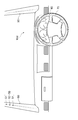
- two infrared irradiation LEDs 51 and one infrared imaging element 52 constituting the eyeball position detection unit 50 are provided on the front pillar on the passenger seat side. It is arranged at a position where the seating situation including the driver's head can be acquired while avoiding the passenger's head of the passenger seat such as the upper part of 90.
- the eyeball position detection unit 51 is provided on the passenger seat side, but may be on the driver seat side when the vehicle seat shape allows a substantially side view from the driver seat side pillar.
- the eyeball position EP in the side view is determined as two-dimensional information based on the driver's head shape, nose protrusion, orbital shape, etc. get.
- the processing device 100 controls the display device 100 to display the display image I at the optimum position for the eyeball position EP in the same manner as in the first embodiment.
- the camera mounting position of the eyeball position detection unit 50 is Even if it is not an ideal side, it should just be a position which can acquire the outline of a driver's side view.
- the camera of the eyeball position detection unit 50 captures the driver even when it is placed near the passenger compartment ceiling from the passenger seat, above the instrument panel 40, in the passenger compartment near the external mirror on the passenger seat side, etc.
- the eyeball position EP can be specified.
- the camera of the eyeball position detection unit 50 has a wide-angle lens and has peripheral distortion
- the eyeball position EP can be specified by simply providing a correction value.
- the eyeball position detection unit 50 is provided on either the left or right inner surface of the passenger compartment of the host vehicle. Therefore, it becomes easy to detect the position of the driver's eyeball position EP in the vehicle front-rear direction and the vehicle vertical direction with high accuracy by side view. Further, it can be assumed that the driver's eyeball position EP is on a line parallel to the front-rear direction of the host vehicle passing through the center of the driver seat 60. Therefore, if the eyeball position detection unit 50 can detect the position of the driver's eyeball position EP in the vehicle front-rear direction and the vehicle vertical direction by side view, information for identifying the driver's eyeball position EP is obtained. Can be obtained. Therefore, the eyeball position EP in the three-dimensional space can be detected with high accuracy.
- the present embodiment has a feature in the method for controlling the display position of the display image I used in combination therewith.
- the display image I needs to follow long-term fluctuations due to changes in the sitting posture of the eyeball position EP.
- the display image I has a margin between the extreme end of the drawing range of the display image I and the extreme end of the viewable range V due to a temporary change in the eyeball position EP due to vehicle vibration or the like. It is desirable to absorb and not change the position of the display image I.
- the driver feels that the display image I is unstable, which may cause car sickness.
- an antiphase control or hunting may occur.
- the display position of the display image I is corrected only when the margin between the extreme end of the drawing range of the display image I and the extreme end of the viewable range V is less than a predetermined amount.
- Hysteresis control is used. For example, as shown in FIG. 8, a constant value such as a distance D / 2 is set for the distance D between the extreme end of the drawing range of the display image I and the extreme end of the viewable range V in FIG.
- the processing apparatus 100 controls the display position of the display image I only when the eyeball position EP is changed by an excessive amount.
- the display image I can be kept stable with respect to the variation in the eyeball position EP within ⁇ the distance D / 2, and the variation in the eyeball position EP exceeding the distance D / 2 can be followed quickly. .
- the threshold value for starting the control of the display position of the display image I is set as, for example, the distance D / 3. Or ⁇ (distance D ⁇ distance C) / 2 ⁇ .
- the HUD image display unit 20 changes the position at which the display image I is displayed when the amount of change in the eyeball position EP detected by the eyeball position detection unit 50 exceeds a predetermined threshold. Therefore, when the change amount of the eyeball position EP is equal to or less than the threshold value, the display image I is stably displayed at the same position, so that hunting or the like can be prevented. Further, when the change amount of the eyeball position EP exceeds the threshold, the display image I can be displayed at a position corresponding to the eyeball position EP.
- the HUD image display unit 20 has an end portion of the display range in which the display image I is displayed and an end portion of the viewable range V within the viewable range V where the driver can visually recognize the entire display image I.
- the position where the display image I is displayed is changed when the shortest distance is less than a predetermined threshold. Therefore, when the change amount of the eyeball position EP is small and the display range of the display image I is within the viewable range V, the display image I is stably displayed at the same position, so that hunting or the like is prevented. be able to.
- the amount of change in the eyeball position EP is large, the distance between the extreme end of the display range and the extreme end of the viewable range V is shortened, and the display range of the display image I is likely to deviate from within the viewable range V.
- the display image I by displaying the display image I at a position corresponding to the eyeball position EP, it is possible to fit the display range within the visible range V.
- the head-up display device of the present invention even if the position of the driver's eyeball fluctuates due to the driver's posture or the like, the displayed image is displayed in the driver's field of view while moving the image to an appropriate position. It can be prevented from being shielded from.
- Head-up display device 20 HUD image display unit 21 HUD image display 22 Image position adjusting concave mirror 23 Open garnish 30 Front windshield 40 Instrument panel 50 Eyeball position detection unit 51 Infrared irradiation LED 52 Infrared imaging device 60 Driver's seat 70 Steering wheel 80 Steering wheel column 90 Pillar
Landscapes
- Engineering & Computer Science (AREA)
- Chemical & Material Sciences (AREA)
- Combustion & Propulsion (AREA)
- Transportation (AREA)
- Mechanical Engineering (AREA)
- Physics & Mathematics (AREA)
- General Physics & Mathematics (AREA)
- Optics & Photonics (AREA)
- Instrument Panels (AREA)
Abstract
Une unité d'affichage (20) d'image ATH pour afficher une image d'affichage (I) règle la position d'affichage de l'image d'affichage (I) en fonction de la position (EP) du globe oculaire du conducteur, détectée par une unité de détection (50) de position de globe oculaire. Par conséquent, même si la position (EP) de globe oculaire change, l'image d'affichage (I) peut se déplacer à une position appropriée. L'unité de détection (50) de position de globe oculaire est disposée de façon à ne pas se chevaucher avec l'axe optique (R) du faisceau lumineux permettant à l'unité d'affichage (20) d'image ATH d'afficher l'image d'affichage (I). Par conséquent, on peut éviter que l'image d'affichage (I) ne soit bloquée par l'unité de détection (50) de position de globe oculaire. En outre, l'unité de détection (50) de position de globe oculaire est installée sur la surface d'un tableau de bord (40). Par conséquent, l'unité de détection (50) de position de globe oculaire peut être disposée au voisinage de l'axe optique (R). Grâce à cela, on réduit l'influence de la parallaxe entre la position de l'unité de détection (50) de position de globe oculaire et l'axe optique (R) sur l'erreur de détection de la position (EP) du globe oculaire. En outre, il devient plus facile de disposer l'unité de détection (50) de position de globe oculaire de façon à ce qu'elle ne se chevauche pas avec l'axe optique (R).
Priority Applications (1)
| Application Number | Priority Date | Filing Date | Title |
|---|---|---|---|
| PCT/JP2010/062785 WO2012014302A1 (fr) | 2010-07-29 | 2010-07-29 | Dispositif d'affichage tête haute |
Applications Claiming Priority (1)
| Application Number | Priority Date | Filing Date | Title |
|---|---|---|---|
| PCT/JP2010/062785 WO2012014302A1 (fr) | 2010-07-29 | 2010-07-29 | Dispositif d'affichage tête haute |
Publications (1)
| Publication Number | Publication Date |
|---|---|
| WO2012014302A1 true WO2012014302A1 (fr) | 2012-02-02 |
Family
ID=45529547
Family Applications (1)
| Application Number | Title | Priority Date | Filing Date |
|---|---|---|---|
| PCT/JP2010/062785 Ceased WO2012014302A1 (fr) | 2010-07-29 | 2010-07-29 | Dispositif d'affichage tête haute |
Country Status (1)
| Country | Link |
|---|---|
| WO (1) | WO2012014302A1 (fr) |
Cited By (8)
| Publication number | Priority date | Publication date | Assignee | Title |
|---|---|---|---|---|
| JP2015048040A (ja) * | 2013-09-04 | 2015-03-16 | トヨタ自動車株式会社 | 注意喚起表示装置及び注意喚起表示方法 |
| CN105083167A (zh) * | 2014-05-05 | 2015-11-25 | 通用汽车环球科技运作有限责任公司 | 用于使用眼睛盯视数据控制汽车的系统和方法 |
| CN106483659A (zh) * | 2015-08-24 | 2017-03-08 | 福特全球技术公司 | 用于观察具有抬头显示器的车辆的驾驶员的眼睛的方法 |
| CN108399903A (zh) * | 2018-03-27 | 2018-08-14 | 京东方科技集团股份有限公司 | 一种成像位置的调节方法及装置、平视显示系统 |
| WO2019130695A1 (fr) * | 2017-03-30 | 2019-07-04 | 日本精機株式会社 | Dispositif d'affichage pour véhicule |
| CN110297325A (zh) * | 2018-03-22 | 2019-10-01 | 蔚来汽车有限公司 | 增强现实眼镜和系统及增强现实眼镜显示车上信息的方法 |
| CN110884439A (zh) * | 2019-12-12 | 2020-03-17 | 浙江皓润科技服务有限公司 | 一种汽车影像系统 |
| JP2022021866A (ja) * | 2020-07-22 | 2022-02-03 | 京セラ株式会社 | カメラシステムおよび画像表示システム |
Citations (8)
| Publication number | Priority date | Publication date | Assignee | Title |
|---|---|---|---|---|
| JP2004322680A (ja) * | 2003-04-21 | 2004-11-18 | Denso Corp | ヘッドアップディスプレイ装置 |
| JP2006153459A (ja) * | 2004-11-25 | 2006-06-15 | Nippon Seiki Co Ltd | 車両用表示装置 |
| JP2008094377A (ja) * | 2006-09-14 | 2008-04-24 | Toyota Motor Corp | 車両用表示装置 |
| JP2009139246A (ja) * | 2007-12-07 | 2009-06-25 | Honda Motor Co Ltd | 画像処理装置、画像処理方法、画像処理プログラムおよび位置検出装置並びにそれを備えた移動体 |
| WO2009113484A1 (fr) * | 2008-03-11 | 2009-09-17 | 株式会社ニコン | Dispositif de détection de sphère de référence, dispositif de détection de position de sphère de référence et dispositif de mesure de coordonnées tridimensionnelles |
| JP2009292409A (ja) * | 2008-06-09 | 2009-12-17 | Yazaki Corp | ヘッドアップディスプレイ装置 |
| JP2010006267A (ja) * | 2008-06-27 | 2010-01-14 | Calsonic Kansei Corp | 車両用表示装置 |
| JP2010078626A (ja) * | 2008-09-23 | 2010-04-08 | Denso Corp | ヘッドアップディスプレイ装置の製造方法 |
-
2010
- 2010-07-29 WO PCT/JP2010/062785 patent/WO2012014302A1/fr not_active Ceased
Patent Citations (8)
| Publication number | Priority date | Publication date | Assignee | Title |
|---|---|---|---|---|
| JP2004322680A (ja) * | 2003-04-21 | 2004-11-18 | Denso Corp | ヘッドアップディスプレイ装置 |
| JP2006153459A (ja) * | 2004-11-25 | 2006-06-15 | Nippon Seiki Co Ltd | 車両用表示装置 |
| JP2008094377A (ja) * | 2006-09-14 | 2008-04-24 | Toyota Motor Corp | 車両用表示装置 |
| JP2009139246A (ja) * | 2007-12-07 | 2009-06-25 | Honda Motor Co Ltd | 画像処理装置、画像処理方法、画像処理プログラムおよび位置検出装置並びにそれを備えた移動体 |
| WO2009113484A1 (fr) * | 2008-03-11 | 2009-09-17 | 株式会社ニコン | Dispositif de détection de sphère de référence, dispositif de détection de position de sphère de référence et dispositif de mesure de coordonnées tridimensionnelles |
| JP2009292409A (ja) * | 2008-06-09 | 2009-12-17 | Yazaki Corp | ヘッドアップディスプレイ装置 |
| JP2010006267A (ja) * | 2008-06-27 | 2010-01-14 | Calsonic Kansei Corp | 車両用表示装置 |
| JP2010078626A (ja) * | 2008-09-23 | 2010-04-08 | Denso Corp | ヘッドアップディスプレイ装置の製造方法 |
Cited By (11)
| Publication number | Priority date | Publication date | Assignee | Title |
|---|---|---|---|---|
| JP2015048040A (ja) * | 2013-09-04 | 2015-03-16 | トヨタ自動車株式会社 | 注意喚起表示装置及び注意喚起表示方法 |
| CN105083167A (zh) * | 2014-05-05 | 2015-11-25 | 通用汽车环球科技运作有限责任公司 | 用于使用眼睛盯视数据控制汽车的系统和方法 |
| CN106483659A (zh) * | 2015-08-24 | 2017-03-08 | 福特全球技术公司 | 用于观察具有抬头显示器的车辆的驾驶员的眼睛的方法 |
| WO2019130695A1 (fr) * | 2017-03-30 | 2019-07-04 | 日本精機株式会社 | Dispositif d'affichage pour véhicule |
| JPWO2019130695A1 (ja) * | 2017-03-30 | 2021-01-07 | 日本精機株式会社 | 車両用表示装置 |
| JP7136127B2 (ja) | 2017-03-30 | 2022-09-13 | 日本精機株式会社 | 車両用表示装置 |
| CN110297325A (zh) * | 2018-03-22 | 2019-10-01 | 蔚来汽车有限公司 | 增强现实眼镜和系统及增强现实眼镜显示车上信息的方法 |
| CN110297325B (zh) * | 2018-03-22 | 2023-01-13 | 蔚来控股有限公司 | 增强现实眼镜和系统及增强现实眼镜显示车上信息的方法 |
| CN108399903A (zh) * | 2018-03-27 | 2018-08-14 | 京东方科技集团股份有限公司 | 一种成像位置的调节方法及装置、平视显示系统 |
| CN110884439A (zh) * | 2019-12-12 | 2020-03-17 | 浙江皓润科技服务有限公司 | 一种汽车影像系统 |
| JP2022021866A (ja) * | 2020-07-22 | 2022-02-03 | 京セラ株式会社 | カメラシステムおよび画像表示システム |
Similar Documents
| Publication | Publication Date | Title |
|---|---|---|
| US20120002028A1 (en) | Face image pick-up apparatus for vehicle | |
| US9405120B2 (en) | Head-up display and vehicle using the same | |
| EP3142902B1 (fr) | Dispositif d'affichage et vehicule | |
| JP6221942B2 (ja) | ヘッドアップディスプレイ装置 | |
| JP4702437B2 (ja) | 車両用表示装置 | |
| JP6377508B2 (ja) | 表示装置、制御方法、プログラム、及び記憶媒体 | |
| JP5286750B2 (ja) | 車両用表示装置 | |
| CN109564501B (zh) | 用于控制机动车的显示装置的方法,机动车的显示装置及具有显示装置的机动车 | |
| JP5816311B2 (ja) | 車両用の視認システム | |
| JP5874920B2 (ja) | 車両周囲確認用モニター装置 | |
| CN107444263A (zh) | 车辆用显示装置 | |
| JP6453929B2 (ja) | 車両の表示システム及び車両の表示システムの制御方法 | |
| US9835861B2 (en) | System having an adjustment device and method for automatically adjusting/switching the adjustment device for a head-up display device | |
| JP2011234095A (ja) | 車両用視認支援装置 | |
| JP2009262666A (ja) | 車両用ヘッドアップディスプレイ装置の調整方法 | |
| JP2006044596A (ja) | 車両用表示装置 | |
| JP2006231998A (ja) | フロントピラー死角の視認装置 | |
| KR20150033583A (ko) | 시각 시스템 | |
| WO2020009218A1 (fr) | Dispositif d'affichage tête haute | |
| JP5021094B2 (ja) | ヘッドアップディスプレイ | |
| CN110300911A (zh) | 为车辆使用者显示信息的方法 | |
| JPWO2020090187A1 (ja) | 虚像表示装置、およびヘッドアップディスプレイ装置 | |
| KR101091288B1 (ko) | 자동차용 디스플레이 장치 및 방법 | |
| JP2008018760A (ja) | 運転支援装置 | |
| CN115303181A (zh) | 用于辅助驾驶员监控车辆外部环境的方法和设备 |
Legal Events
| Date | Code | Title | Description |
|---|---|---|---|
| 121 | Ep: the epo has been informed by wipo that ep was designated in this application |
Ref document number: 10855312 Country of ref document: EP Kind code of ref document: A1 |
|
| NENP | Non-entry into the national phase |
Ref country code: DE |
|
| 122 | Ep: pct application non-entry in european phase |
Ref document number: 10855312 Country of ref document: EP Kind code of ref document: A1 |
|
| NENP | Non-entry into the national phase |
Ref country code: JP |