WO2012014334A1 - 乗り物用シート構造 - Google Patents
乗り物用シート構造 Download PDFInfo
- Publication number
- WO2012014334A1 WO2012014334A1 PCT/JP2010/066233 JP2010066233W WO2012014334A1 WO 2012014334 A1 WO2012014334 A1 WO 2012014334A1 JP 2010066233 W JP2010066233 W JP 2010066233W WO 2012014334 A1 WO2012014334 A1 WO 2012014334A1
- Authority
- WO
- WIPO (PCT)
- Prior art keywords
- rail
- seat
- fixed
- fixed rail
- safety belt
- Prior art date
- Legal status (The legal status is an assumption and is not a legal conclusion. Google has not performed a legal analysis and makes no representation as to the accuracy of the status listed.)
- Ceased
Links
Images



Classifications
-
- B—PERFORMING OPERATIONS; TRANSPORTING
- B60—VEHICLES IN GENERAL
- B60N—SEATS SPECIALLY ADAPTED FOR VEHICLES; VEHICLE PASSENGER ACCOMMODATION NOT OTHERWISE PROVIDED FOR
- B60N2/00—Seats specially adapted for vehicles; Arrangement or mounting of seats in vehicles
- B60N2/02—Seats specially adapted for vehicles; Arrangement or mounting of seats in vehicles the seat or part thereof being movable, e.g. adjustable
- B60N2/04—Seats specially adapted for vehicles; Arrangement or mounting of seats in vehicles the seat or part thereof being movable, e.g. adjustable the whole seat being movable
- B60N2/06—Seats specially adapted for vehicles; Arrangement or mounting of seats in vehicles the seat or part thereof being movable, e.g. adjustable the whole seat being movable slidable
- B60N2/07—Slide construction
- B60N2/0722—Constructive details
-
- B—PERFORMING OPERATIONS; TRANSPORTING
- B60—VEHICLES IN GENERAL
- B60N—SEATS SPECIALLY ADAPTED FOR VEHICLES; VEHICLE PASSENGER ACCOMMODATION NOT OTHERWISE PROVIDED FOR
- B60N2/00—Seats specially adapted for vehicles; Arrangement or mounting of seats in vehicles
- B60N2/005—Arrangement or mounting of seats in vehicles, e.g. dismountable auxiliary seats
- B60N2/015—Attaching seats directly to vehicle chassis
-
- B—PERFORMING OPERATIONS; TRANSPORTING
- B60—VEHICLES IN GENERAL
- B60N—SEATS SPECIALLY ADAPTED FOR VEHICLES; VEHICLE PASSENGER ACCOMMODATION NOT OTHERWISE PROVIDED FOR
- B60N2/00—Seats specially adapted for vehicles; Arrangement or mounting of seats in vehicles
- B60N2/02—Seats specially adapted for vehicles; Arrangement or mounting of seats in vehicles the seat or part thereof being movable, e.g. adjustable
- B60N2/04—Seats specially adapted for vehicles; Arrangement or mounting of seats in vehicles the seat or part thereof being movable, e.g. adjustable the whole seat being movable
- B60N2/06—Seats specially adapted for vehicles; Arrangement or mounting of seats in vehicles the seat or part thereof being movable, e.g. adjustable the whole seat being movable slidable
-
- B—PERFORMING OPERATIONS; TRANSPORTING
- B60—VEHICLES IN GENERAL
- B60N—SEATS SPECIALLY ADAPTED FOR VEHICLES; VEHICLE PASSENGER ACCOMMODATION NOT OTHERWISE PROVIDED FOR
- B60N2/00—Seats specially adapted for vehicles; Arrangement or mounting of seats in vehicles
- B60N2/02—Seats specially adapted for vehicles; Arrangement or mounting of seats in vehicles the seat or part thereof being movable, e.g. adjustable
- B60N2/04—Seats specially adapted for vehicles; Arrangement or mounting of seats in vehicles the seat or part thereof being movable, e.g. adjustable the whole seat being movable
- B60N2/06—Seats specially adapted for vehicles; Arrangement or mounting of seats in vehicles the seat or part thereof being movable, e.g. adjustable the whole seat being movable slidable
- B60N2/065—Rear seats
-
- B—PERFORMING OPERATIONS; TRANSPORTING
- B60—VEHICLES IN GENERAL
- B60N—SEATS SPECIALLY ADAPTED FOR VEHICLES; VEHICLE PASSENGER ACCOMMODATION NOT OTHERWISE PROVIDED FOR
- B60N2/00—Seats specially adapted for vehicles; Arrangement or mounting of seats in vehicles
- B60N2/02—Seats specially adapted for vehicles; Arrangement or mounting of seats in vehicles the seat or part thereof being movable, e.g. adjustable
- B60N2/04—Seats specially adapted for vehicles; Arrangement or mounting of seats in vehicles the seat or part thereof being movable, e.g. adjustable the whole seat being movable
- B60N2/06—Seats specially adapted for vehicles; Arrangement or mounting of seats in vehicles the seat or part thereof being movable, e.g. adjustable the whole seat being movable slidable
- B60N2/07—Slide construction
- B60N2/0702—Slide construction characterised by its cross-section
- B60N2/0715—C or U-shaped
-
- B—PERFORMING OPERATIONS; TRANSPORTING
- B60—VEHICLES IN GENERAL
- B60N—SEATS SPECIALLY ADAPTED FOR VEHICLES; VEHICLE PASSENGER ACCOMMODATION NOT OTHERWISE PROVIDED FOR
- B60N2/00—Seats specially adapted for vehicles; Arrangement or mounting of seats in vehicles
- B60N2/02—Seats specially adapted for vehicles; Arrangement or mounting of seats in vehicles the seat or part thereof being movable, e.g. adjustable
- B60N2/04—Seats specially adapted for vehicles; Arrangement or mounting of seats in vehicles the seat or part thereof being movable, e.g. adjustable the whole seat being movable
- B60N2/06—Seats specially adapted for vehicles; Arrangement or mounting of seats in vehicles the seat or part thereof being movable, e.g. adjustable the whole seat being movable slidable
- B60N2/07—Slide construction
- B60N2/0722—Constructive details
- B60N2/073—Reinforcement members preventing slide dislocation
-
- B—PERFORMING OPERATIONS; TRANSPORTING
- B60—VEHICLES IN GENERAL
- B60R—VEHICLES, VEHICLE FITTINGS, OR VEHICLE PARTS, NOT OTHERWISE PROVIDED FOR
- B60R22/00—Safety belts or body harnesses in vehicles
- B60R22/18—Anchoring devices
Definitions
- the present invention relates to a seat structure for a vehicle such as an automobile, a ship, an aircraft, and a railway vehicle, and more particularly to a one-box type automobile seat structure.
- a seat in which two people can sit side by side and a seat in which one person sits are configured in a 6: 4 dimensional relationship.
- Each seat is slidable back and forth by slide rails arranged in parallel on the floor.
- a safety belt capable of restraining three passengers for convenience is arranged on a seat where two people can sit side by side and a seat where one person can sit.
- One base end of the safety belt is fixed to the vehicle body and / or the frame of the seat.
- the other base end of the safety belt is provided on the slide rail so that the position in the front-rear direction can be changed as the seat moves (see Patent Document 1). Thereby, the safety belt can be mounted regardless of the position of the seat in the front-rear direction.
- the base end of the safety belt for two people provided on the seat where two people can sit side by side is provided on one slide rail of the seat where two people can sit side by side. For this reason, a big load will concentrate on one slide rail. If a strength member is provided on the slide rail in order to obtain a strength that can withstand this load, the weight of the slide rail will increase significantly, and the fuel consumption of the automobile may be deteriorated.
- an object of the present invention is to provide a vehicle seat structure that is lightweight while increasing the strength of a slide rail.
- a vehicle seat structure includes a fixing member that is fixed to the floor at a distance from the front and the back, an aluminum fixed rail that is held by the fixing member, and a fixing member.
- a slide rail composed of a movable rail that can move back and forth with respect to the rail, a seat cushion fixed to the movable rail, a seat back supported by the seat cushion, and within a safety belt use area in the fixed rail, and And an iron reinforcing plate fixed at a position avoiding the fixing member.
- the strength of the slide rail can be increased with respect to the load applied to the safety belt. Further, since the reinforcing plate is fixed only in a position where the fixing rail is in the safety belt use area and avoids the fixing member, the reinforcing plate can be reduced in size and weight.
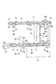
- FIG. 1 is a perspective view showing a vehicle seat according to an embodiment of the present invention.
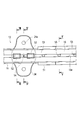
- FIG. 2 is a top view showing only the slide rail of the vehicle seat that allows two persons in FIG. 1 to sit side by side.
- FIG. 3 is an enlarged top view showing a portion III in FIG.
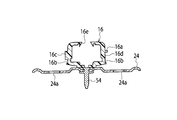
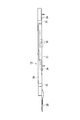
- FIG. 4 is a cross-sectional view of the slide rail taken along line IV-IV in FIG.
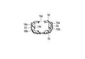
- FIG. 5 is a cross-sectional view of the slide rail taken along line VV in FIG.
- FIG. 6 is a cross-sectional view of the slide rail taken along line VI-VI in FIG.
- FIG. 7 is a cross-sectional view of the slide rail taken along line VII-VII in FIG.
- FIG. 8 is an explanatory side view according to an arrow VIII in FIG.
- Reference numeral 1 shown in FIG. 1 is a seat for two people where two people can sit side by side.
- Reference numeral 2 denotes a seat for one person where one person sits.
- the two-seat seat 1 is slidable in the front-rear direction by an outer slide rail 11 and an inner slide rail 12 that are arranged side by side on the floor 46 of the vehicle.
- the single-seat seat 2 is slidable in the front-rear direction by the outer slide rail 13 and the inner slide rail 14 that are arranged side by side on the floor 46.
- the two-seat seat 1 includes an outer seat 3 on the frame side of a vehicle body (not shown) and an inner seat 4 on the center side of the vehicle.
- the outer seat 3 of the two-seat seat 1 includes a seat back 5 having a headrest 5 a and a seat cushion 6.
- the inner seat 4 of the two-seat seat 1 includes a seat back 7 having a headrest 7 a and a seat cushion 8.
- the single-seat seat 2 includes a seat back 9 having a headrest 9 a and a seat cushion 10.
- safety belts 32, 35, and 38 that can restrain three passengers (not shown) are arranged on the two-seat seat 1 and the one-seat seat 2.
- the safety belt 32 includes a lap belt 30 and a shoulder belt 31.
- the safety belt 35 includes a lap belt 33 and a shoulder belt 34.
- the safety belt 38 includes a lap belt 36 and a shoulder belt 37.
- One base end side 31a, 37a of the safety belts 32, 38 is fixed to a frame of a vehicle body (not shown).
- One base end side 34 a of the safety belt 35 is wound up by a retractor or the like provided on a frame (not shown) of the seat back 7.
- the other base end side 30 a of the safety belt 32 is provided on a movable rail (not shown) that is slidable with respect to the fixed rail 15 of the outer slide rail 11.
- the front-rear position of the base end side 30a can be changed in accordance with the front-rear movement of the outer seat 3.
- the safety belt 32 can be mounted regardless of whether the outer seat 3 of the two-seat seat 1 is in the front or back position.
- the other base end side 33 a of the safety belt 35 is provided on a movable rail (not shown) that can slide on the fixed rail 16 of the inner slide rail 12.
- the front-rear position of the base end side 33 a can be changed in accordance with the front-rear movement of the inner seat 4.
- the safety belt 35 can be mounted regardless of whether the inner seat 4 of the two-seat seat 1 is in the front or back position.
- the tongue plate 39 movably disposed on the safety belt 32 can be fixed to the buckle 42 disposed between the outer seat 3 and the inner seat 4 and can be detached from the buckle 42.
- the tongue plate 40 movably disposed on the safety belt 35 can be fixed to and removed from the buckle 43 disposed between the inner seat 4 and the one-seat seat 2.
- the tongue plate 41 movably disposed on the safety belt 38 can be fixed to the buckle 44 disposed between the inner seat 4 and the single seat 2 and can be detached from the buckle 44.
- the outer slide rail 11 includes a fixed rail 15 and a movable rail (not shown) that can move back and forth within the fixed rail 15.
- the fixed rail 15 is arranged at the front first leg 19 protruding to the front side of the fixed rail 15, the first bracket 23 protruding to the side of the fixed rail 15, and the rear end portion of the fixed rail 15.
- the back side first leg 28 is fixed to the floor 46.
- Bolt insertion holes 19a, 23a, and 28a are formed in the front first leg 19, the first bracket 23, and the rear first leg 28, respectively.
- the fixing rail 15 is fixed to the floor 46 by inserting bolts (not shown) into the bolt insertion holes 19a, 23a, and 28a.
- the floor fixing bracket 50 shown in FIG. 2 protrudes to the side of the fixed rail 15 like the first bracket 23.
- Reference numeral 50 a is a bolt insertion hole formed in the floor fixing bracket 50.
- a second bracket 24, which is a “fixing member”, is disposed below the fixed rail 16.
- the second bracket 24 is fixed to the fixed rail 16 by a first rivet 52.
- an iron reinforcing plate 51 is disposed between the second brackets 24 and 24 of the fixed rail 16 made of aluminum.
- the reinforcing plate 51 is disposed below the fixed rail 16 and is fixed to the fixed rail 16 by a second rivet 53.
- reference numeral 54 denotes a third rivet that also serves as a positioning with respect to the floor 46.
- reference numeral 55 denotes a rail cover bracket.
- the inner slide rail 12 includes a fixed rail 16 and a movable rail (not shown) that can move back and forth within the fixed rail 16.
- the fixed rail 16 is fixed to the floor 46 by a front second leg 20 protruding obliquely forward of the fixed rail 16 and a second bracket 24 protruding laterally of the fixed rail 16.
- Bolt insertion holes 20 a and 24 a are formed in the front second leg 20 and the second bracket 24, respectively, and bolts (not shown) are inserted into the insertion holes 20 a and 24 a to fix the fixed rail 16 to the floor 46.
- the fixed rail 16 includes a first side wall portion 16c which is a vertical wall-like “one side wall portion”, a second side wall portion 16d which is a “second side wall portion”, and a second side wall portion 16d.
- the engaging portion 16a protrudes so that the end portions 51a and 51a of the reinforcing plate 51 can be engaged.
- the first side wall portion 16c of the fixed rail 16 is provided with an engagement port 56 that can engage a latch (not shown), and the first side wall portion 16c is thicker than the second side wall portion 16d. It is said.
- the outer slide rail 13 includes a fixed rail 17 and a movable rail (not shown) that can move back and forth in the fixed rail 17.
- the fixed rail 17 is fixed to the floor 46 by a front third leg 21 protruding to the front side of the fixed rail 17 and a third bracket 25 protruding to the side of the fixed rail 17.
- Bolt insertion holes 21 a and 25 a are respectively formed in the front third leg 21 and the third bracket 25, and bolts (not shown) are inserted into the bolt insertion holes 21 a and 25 a and fixed to the floor 46.
- the inner slide rail 14 includes a fixed rail 18 and a movable rail (not shown) that can move back and forth in the fixed rail 18.
- the fixed rail 18 is fixed to the floor 46 by a front fourth leg 22 that protrudes diagonally forward of the fixed rail 18 and a fourth bracket 26 that protrudes laterally of the fixed rail 18.
- Bolt insertion holes 22a and 26a are respectively formed in the front fourth leg 22 and the fourth bracket 26, and bolts (not shown) are inserted into the bolt insertion holes 22a and 26a and fixed to the floor 46.
- the fixed rails 15, 16, 17, 18, in particular, the fixed rail 16 is made of aluminum, and the iron reinforcing plate is a second bracket that is in the safety belt use area of the fixed rail 16 and is a fixed member. It is fixed at a position avoiding 24. Therefore, the safety belts 32 and 35 can increase the strength of the inner slide rail 12, particularly the fixed rail 16, with respect to a large load applied to the fixed rail 16 of the inner slide rail 12. Further, the range in which the reinforcing plate 51 is provided is only in a position within the safety belt use region 27 and avoiding the second bracket 24 which is a fixing member. Thereby, the reinforcement plate 51 can be reduced in size and can be reduced in weight. Further, the fixed rail 16 made of aluminum and the reinforcing plate 51 made of iron, which cannot be welded, are fixed by the second rivet 53, so that the reinforcing plate 51 can support the fixed rail 16 reliably.
- the fixed rail 16 has the engaging portions 16a and 16a that can engage the reinforcing plate 51, the reinforcing plate 51 can be easily supported by the fixed rail 16.
- the first side wall portion 16c of the fixed rail 16 is formed with an engagement port 56 that can engage the latch, and the first side wall portion 16c is thicker than the second side wall portion 16d.
- the seat structure for an automobile is described.
- the seat structure for a vehicle such as a ship, an aircraft, and a railway vehicle is not limited to the automobile.
- the vehicle seat structure includes the fixing member 24 that is fixed to the floor in the front-rear direction and the fixed rail 16 made of aluminum that is held by the fixing member 24. And a slide rail 12 made of a movable rail movable back and forth with respect to the fixed rail 16, seat cushions 6 and 8 fixed to the movable rail, and seat backs 5 and 7 supported by the seat cushions 6 and 8, And a reinforcing plate 51 made of iron, which is fixed within the safety belt usage region 27 of the fixed rail 16 and at a position avoiding the fixing member 24.
- strength of the slide rail 12 can be increased with respect to the load added to a safety belt.
- the reinforcing plate 51 is fixed only within the safety belt usage region 27 of the fixed rail 16 and at a position avoiding the fixing member 24, the reinforcing plate 51 can be reduced in size and weight. Therefore, the vehicle seat structure according to the embodiment of the present invention can be used industrially.
Landscapes
- Engineering & Computer Science (AREA)
- Mechanical Engineering (AREA)
- Aviation & Aerospace Engineering (AREA)
- Transportation (AREA)
- Seats For Vehicles (AREA)
- Automotive Seat Belt Assembly (AREA)
Abstract
Description
Claims (3)
- 床に前後に離間して固定される固定部材と、
該固定部材により保持されてなるアルミニューム製の固定レール及び該固定レールに対して前後移動可能なる可動レールよりなるスライドレールと、
前記可動レールに固定されてなるシートクッションと、
該シートクッションに支持されてなるシートバックと、
前記固定レールにおける安全ベルト使用領域内であって且つ前記固定部材を避けた位置に固定された鉄製の補強プレートと
を備えることを特徴とする乗り物用シート構造。 - 請求項1記載の乗り物用シート構造であって、
前記固定レールは、前記補強プレートを係合可能なる係合部を有することを特徴とする乗り物用シート構造。 - 請求項1又は請求項2記載の乗り物用シート構造であって、
前記固定レールの一方の側壁部には、ラッチが係合可能なる係合口が形成され、該一方の側壁部は、前記固定レールの他方の側壁部より厚肉としたことを特徴とする乗り物用シート構造。
Priority Applications (3)
| Application Number | Priority Date | Filing Date | Title |
|---|---|---|---|
| CN201080068323.4A CN103038093B (zh) | 2010-07-29 | 2010-09-17 | 交通工具用座椅构造 |
| US13/812,822 US8985666B2 (en) | 2010-07-29 | 2010-09-17 | Structure for vehicle seat |
| EP10855341.3A EP2599657B1 (en) | 2010-07-29 | 2010-09-17 | Structure for vehicle seat |
Applications Claiming Priority (2)
| Application Number | Priority Date | Filing Date | Title |
|---|---|---|---|
| JP2010-170358 | 2010-07-29 | ||
| JP2010170358A JP5690093B2 (ja) | 2010-07-29 | 2010-07-29 | 乗り物用シート構造 |
Publications (1)
| Publication Number | Publication Date |
|---|---|
| WO2012014334A1 true WO2012014334A1 (ja) | 2012-02-02 |
Family
ID=45529576
Family Applications (1)
| Application Number | Title | Priority Date | Filing Date |
|---|---|---|---|
| PCT/JP2010/066233 Ceased WO2012014334A1 (ja) | 2010-07-29 | 2010-09-17 | 乗り物用シート構造 |
Country Status (5)
| Country | Link |
|---|---|
| US (1) | US8985666B2 (ja) |
| EP (1) | EP2599657B1 (ja) |
| JP (1) | JP5690093B2 (ja) |
| CN (1) | CN103038093B (ja) |
| WO (1) | WO2012014334A1 (ja) |
Cited By (1)
| Publication number | Priority date | Publication date | Assignee | Title |
|---|---|---|---|---|
| CN109466501A (zh) * | 2018-11-23 | 2019-03-15 | 安徽江淮汽车集团股份有限公司 | 一种安全带插锁安装结构 |
Families Citing this family (14)
| Publication number | Priority date | Publication date | Assignee | Title |
|---|---|---|---|---|
| JP6498913B2 (ja) * | 2014-11-11 | 2019-04-10 | テイ・エス テック株式会社 | 車両用シート |
| CN107107791B (zh) | 2014-11-11 | 2020-03-17 | 提爱思科技股份有限公司 | 车用座椅 |
| JP6286493B2 (ja) * | 2016-08-01 | 2018-02-28 | 株式会社タチエス | 車両用シート |
| FR3058942B1 (fr) * | 2016-11-21 | 2021-06-11 | Peugeot Citroen Automobiles Sa | Dispositif de renfort amovible de la glissiere d’un siege d’un vehicule sur un support |
| JP6796540B2 (ja) * | 2017-04-21 | 2020-12-09 | 株式会社タチエス | 乗り物用シート |
| DE102017007844B4 (de) * | 2017-08-18 | 2022-01-05 | Audi Ag | Fahrzeugsitz für ein Kraftfahrzeug und Kraftfahrzeug |
| WO2021140181A1 (de) | 2020-01-10 | 2021-07-15 | Adient Engineering and IP GmbH | Längseinsteller und fahrzeugsitz |
| DE102020108378B4 (de) * | 2020-01-10 | 2024-01-04 | Adient Us Llc | Längseinsteller und fahrzeugsitz |
| US11014472B1 (en) | 2020-03-24 | 2021-05-25 | Adient Engineering and IP GmbH | Vehicle seat slide structure |
| CN112009319A (zh) * | 2020-09-22 | 2020-12-01 | 长春富维安道拓汽车饰件系统有限公司 | 一种汽车座椅用下滑轨型材 |
| EP4366980B1 (de) | 2021-07-06 | 2025-09-17 | Adient US LLC | Vorrichtung zur befestigung eines längseinstellers für einen fahrzeugsitz an einer fahrzeugstruktur, sowie fahrzeug |
| DE102021122640A1 (de) | 2021-07-06 | 2023-01-12 | Adient Us Llc | Vorrichtung zur befestigung eines längseinstellers für einen fahrzeugsitz an einer fahrzeugstruktur, sowie fahrzeug |
| JP2024044981A (ja) * | 2022-09-21 | 2024-04-02 | テイ・エス テック株式会社 | スライドレール装置 |
| JP7848586B2 (ja) * | 2022-05-16 | 2026-04-21 | マツダ株式会社 | 車両の下部車体構造 |
Citations (5)
| Publication number | Priority date | Publication date | Assignee | Title |
|---|---|---|---|---|
| JPH0353330U (ja) * | 1989-09-30 | 1991-05-23 | ||
| JPH04201636A (ja) * | 1990-11-30 | 1992-07-22 | Aisin Seiki Co Ltd | 車両用シートスライド装置 |
| JP2009509832A (ja) * | 2005-09-30 | 2009-03-12 | ジョンソン・コントロールズ・ゲー・エム・ベー・ハー | 自動車用シートの調整装置 |
| JP2010120554A (ja) | 2008-11-20 | 2010-06-03 | Nhk Spring Co Ltd | 車両用シートのスライド構造および該構造を有する車両用シート |
| JP2010170358A (ja) | 2009-01-23 | 2010-08-05 | Ihi Corp | 船体動揺の粘性境界層による減衰比の予測方法 |
Family Cites Families (22)
| Publication number | Priority date | Publication date | Assignee | Title |
|---|---|---|---|---|
| AU565466B2 (en) * | 1983-12-06 | 1987-09-17 | Tachikawa Spring Co. Ltd. | Vehicle seat slide |
| AU592382B2 (en) * | 1986-11-07 | 1990-01-11 | Tachi-S Co., Ltd. | Seat slide device |
| US4787667A (en) * | 1987-06-11 | 1988-11-29 | Tachi-S Co. | Seat slide device |
| US4832409A (en) * | 1987-09-08 | 1989-05-23 | General Motors Corporation | Restraint belt load capacity fore and aft power seat adjuster apparatus |
| JPH054750Y2 (ja) * | 1987-10-26 | 1993-02-05 | ||
| JPH0353330A (ja) | 1989-07-20 | 1991-03-07 | Toshiba Corp | 仮説管理検証装置 |
| JP3043819B2 (ja) * | 1991-01-21 | 2000-05-22 | アイシン精機株式会社 | 車両用シートスライド装置 |
| JP2677496B2 (ja) * | 1992-10-28 | 1997-11-17 | 池田物産株式会社 | シートスライド装置 |
| JP2596235Y2 (ja) * | 1993-10-13 | 1999-06-07 | 株式会社タチエス | シートスライド装置 |
| US5620161A (en) * | 1995-08-25 | 1997-04-15 | Track Corp. | Locking pedestal for automotive seating |
| US6059345A (en) * | 1998-06-18 | 2000-05-09 | Tachi-S Co., Ltd. | Slide rail device for vehicle seat |
| EP1103413B1 (en) * | 1999-11-29 | 2006-05-03 | Fujikiko Kabushiki Kaisha | Structure of support leg member for seat slide device |
| US6502887B1 (en) * | 2001-06-29 | 2003-01-07 | Daimlerchrysler Corporation | Arrangement for mounting a restraint belt mounted vehicle seat to a vehicle floor |
| US7823950B2 (en) * | 2004-03-31 | 2010-11-02 | Mazda Motor Corporation | Seat device for vehicle |
| JP4940654B2 (ja) * | 2005-12-22 | 2012-05-30 | アイシン精機株式会社 | 車両用シート装置 |
| US8038217B2 (en) * | 2007-03-29 | 2011-10-18 | Toyota Boshoku Kabushiki Kaisha | Vehicle seat |
| US8061756B2 (en) * | 2008-03-31 | 2011-11-22 | Fuji Kiko Co., Ltd. | Electrically operated seat slide apparatus |
| JP5293026B2 (ja) * | 2008-09-12 | 2013-09-18 | アイシン精機株式会社 | 車両用パワーシート装置 |
| JP5446373B2 (ja) * | 2009-03-27 | 2014-03-19 | アイシン精機株式会社 | 駆動伝達装置及び車両用シートスライド装置 |
| JP5471132B2 (ja) * | 2009-08-04 | 2014-04-16 | アイシン精機株式会社 | 車両用シートスライド装置 |
| WO2011027716A1 (ja) * | 2009-09-04 | 2011-03-10 | アイシン精機 株式会社 | 車両用シートスライド装置 |
| US8398141B2 (en) * | 2010-12-10 | 2013-03-19 | Honda Motor Co., Ltd. | Vehicle seating arrangement for a vehicle seat including a cantilevered section |
-
2010
- 2010-07-29 JP JP2010170358A patent/JP5690093B2/ja active Active
- 2010-09-17 EP EP10855341.3A patent/EP2599657B1/en active Active
- 2010-09-17 US US13/812,822 patent/US8985666B2/en active Active
- 2010-09-17 WO PCT/JP2010/066233 patent/WO2012014334A1/ja not_active Ceased
- 2010-09-17 CN CN201080068323.4A patent/CN103038093B/zh active Active
Patent Citations (5)
| Publication number | Priority date | Publication date | Assignee | Title |
|---|---|---|---|---|
| JPH0353330U (ja) * | 1989-09-30 | 1991-05-23 | ||
| JPH04201636A (ja) * | 1990-11-30 | 1992-07-22 | Aisin Seiki Co Ltd | 車両用シートスライド装置 |
| JP2009509832A (ja) * | 2005-09-30 | 2009-03-12 | ジョンソン・コントロールズ・ゲー・エム・ベー・ハー | 自動車用シートの調整装置 |
| JP2010120554A (ja) | 2008-11-20 | 2010-06-03 | Nhk Spring Co Ltd | 車両用シートのスライド構造および該構造を有する車両用シート |
| JP2010170358A (ja) | 2009-01-23 | 2010-08-05 | Ihi Corp | 船体動揺の粘性境界層による減衰比の予測方法 |
Non-Patent Citations (1)
| Title |
|---|
| See also references of EP2599657A4 |
Cited By (1)
| Publication number | Priority date | Publication date | Assignee | Title |
|---|---|---|---|---|
| CN109466501A (zh) * | 2018-11-23 | 2019-03-15 | 安徽江淮汽车集团股份有限公司 | 一种安全带插锁安装结构 |
Also Published As
| Publication number | Publication date |
|---|---|
| CN103038093A (zh) | 2013-04-10 |
| EP2599657B1 (en) | 2016-11-02 |
| US8985666B2 (en) | 2015-03-24 |
| JP5690093B2 (ja) | 2015-03-25 |
| US20130214551A1 (en) | 2013-08-22 |
| EP2599657A1 (en) | 2013-06-05 |
| EP2599657A4 (en) | 2014-07-23 |
| CN103038093B (zh) | 2015-08-19 |
| JP2012030638A (ja) | 2012-02-16 |
Similar Documents
| Publication | Publication Date | Title |
|---|---|---|
| JP5690093B2 (ja) | 乗り物用シート構造 | |
| CN105015379B (zh) | 交通工具用座椅 | |
| EP2644443B1 (en) | Vehicle seat | |
| US10106060B2 (en) | Vehicle seat | |
| US20060049682A1 (en) | Vehicle rear seat device | |
| JP2009154691A (ja) | 車両用シート | |
| JP2014034226A (ja) | 車両用シート | |
| CA2775789C (en) | Webbing adjuster for a seat belt assembly | |
| CN107031739A (zh) | 车身底板结构 | |
| KR20060117193A (ko) | 차량용 시트의 슬라이드 장치 | |
| JP2017013639A (ja) | 車両用シートレール | |
| CN111216604A (zh) | 车辆用座椅构造 | |
| EP2595844B1 (en) | A seat belt arrangement | |
| JP4396566B2 (ja) | 車両用シート支持部の構造 | |
| JP2009154690A (ja) | 車両用シート | |
| JP7318405B2 (ja) | 車両用シート構造 | |
| JP2012126284A (ja) | シートベルト装置のリトラクタ取り付け構造 | |
| JP2011225102A (ja) | 車両用シート | |
| JP6513736B2 (ja) | 車両用シートレール | |
| JP2004025940A (ja) | 乗り物用シート | |
| JPH0810041Y2 (ja) | 自動車用シート | |
| JP3558931B2 (ja) | 自動車のシート装置における補強構造 | |
| JP3621309B2 (ja) | 自動車のシート補強構造 | |
| JP2001097098A (ja) | 自動車のシート支持装置 | |
| WO2013141271A1 (ja) | 車両のシートレール取付構造 |
Legal Events
| Date | Code | Title | Description |
|---|---|---|---|
| WWE | Wipo information: entry into national phase |
Ref document number: 201080068323.4 Country of ref document: CN |
|
| 121 | Ep: the epo has been informed by wipo that ep was designated in this application |
Ref document number: 10855341 Country of ref document: EP Kind code of ref document: A1 |
|
| NENP | Non-entry into the national phase |
Ref country code: DE |
|
| REEP | Request for entry into the european phase |
Ref document number: 2010855341 Country of ref document: EP |
|
| WWE | Wipo information: entry into national phase |
Ref document number: 2010855341 Country of ref document: EP |
|
| WWE | Wipo information: entry into national phase |
Ref document number: 13812822 Country of ref document: US |