WO2012014522A1 - 摺動部材とその製造方法 - Google Patents
摺動部材とその製造方法 Download PDFInfo
- Publication number
- WO2012014522A1 WO2012014522A1 PCT/JP2011/056729 JP2011056729W WO2012014522A1 WO 2012014522 A1 WO2012014522 A1 WO 2012014522A1 JP 2011056729 W JP2011056729 W JP 2011056729W WO 2012014522 A1 WO2012014522 A1 WO 2012014522A1
- Authority
- WO
- WIPO (PCT)
- Prior art keywords
- sliding member
- annealed
- quenched
- sliding
- remaining
- Prior art date
- Legal status (The legal status is an assumption and is not a legal conclusion. Google has not performed a legal analysis and makes no representation as to the accuracy of the status listed.)
- Ceased
Links
Images




Classifications
-
- F—MECHANICAL ENGINEERING; LIGHTING; HEATING; WEAPONS; BLASTING
- F16—ENGINEERING ELEMENTS AND UNITS; GENERAL MEASURES FOR PRODUCING AND MAINTAINING EFFECTIVE FUNCTIONING OF MACHINES OR INSTALLATIONS; THERMAL INSULATION IN GENERAL
- F16C—SHAFTS; FLEXIBLE SHAFTS; ELEMENTS OR CRANKSHAFT MECHANISMS; ROTARY BODIES OTHER THAN GEARING ELEMENTS; BEARINGS
- F16C17/00—Sliding-contact bearings for exclusively rotary movement
- F16C17/12—Sliding-contact bearings for exclusively rotary movement characterised by features not related to the direction of the load
-
- F—MECHANICAL ENGINEERING; LIGHTING; HEATING; WEAPONS; BLASTING
- F16—ENGINEERING ELEMENTS AND UNITS; GENERAL MEASURES FOR PRODUCING AND MAINTAINING EFFECTIVE FUNCTIONING OF MACHINES OR INSTALLATIONS; THERMAL INSULATION IN GENERAL
- F16C—SHAFTS; FLEXIBLE SHAFTS; ELEMENTS OR CRANKSHAFT MECHANISMS; ROTARY BODIES OTHER THAN GEARING ELEMENTS; BEARINGS
- F16C33/00—Parts of bearings; Special methods for making bearings or parts thereof
- F16C33/02—Parts of sliding-contact bearings
- F16C33/04—Brasses; Bushes; Linings
- F16C33/06—Sliding surface mainly made of metal
- F16C33/10—Construction relative to lubrication
-
- C—CHEMISTRY; METALLURGY
- C21—METALLURGY OF IRON
- C21D—MODIFYING THE PHYSICAL STRUCTURE OF FERROUS METALS; GENERAL DEVICES FOR HEAT TREATMENT OF FERROUS OR NON-FERROUS METALS OR ALLOYS; MAKING METAL MALLEABLE, e.g. BY DECARBURISATION OR TEMPERING
- C21D1/00—General methods or devices for heat treatment, e.g. annealing, hardening, quenching or tempering
- C21D1/06—Surface hardening
- C21D1/09—Surface hardening by direct application of electrical or wave energy; by particle radiation
-
- C—CHEMISTRY; METALLURGY
- C21—METALLURGY OF IRON
- C21D—MODIFYING THE PHYSICAL STRUCTURE OF FERROUS METALS; GENERAL DEVICES FOR HEAT TREATMENT OF FERROUS OR NON-FERROUS METALS OR ALLOYS; MAKING METAL MALLEABLE, e.g. BY DECARBURISATION OR TEMPERING
- C21D1/00—General methods or devices for heat treatment, e.g. annealing, hardening, quenching or tempering
- C21D1/34—Methods of heating
- C21D1/38—Heating by cathodic discharges
-
- C—CHEMISTRY; METALLURGY
- C21—METALLURGY OF IRON
- C21D—MODIFYING THE PHYSICAL STRUCTURE OF FERROUS METALS; GENERAL DEVICES FOR HEAT TREATMENT OF FERROUS OR NON-FERROUS METALS OR ALLOYS; MAKING METAL MALLEABLE, e.g. BY DECARBURISATION OR TEMPERING
- C21D9/00—Heat treatment, e.g. annealing, hardening, quenching or tempering, adapted for particular articles; Furnaces therefor
-
- C—CHEMISTRY; METALLURGY
- C21—METALLURGY OF IRON
- C21D—MODIFYING THE PHYSICAL STRUCTURE OF FERROUS METALS; GENERAL DEVICES FOR HEAT TREATMENT OF FERROUS OR NON-FERROUS METALS OR ALLOYS; MAKING METAL MALLEABLE, e.g. BY DECARBURISATION OR TEMPERING
- C21D9/00—Heat treatment, e.g. annealing, hardening, quenching or tempering, adapted for particular articles; Furnaces therefor
- C21D9/0068—Heat treatment, e.g. annealing, hardening, quenching or tempering, adapted for particular articles; Furnaces therefor for particular articles not mentioned below
-
- F—MECHANICAL ENGINEERING; LIGHTING; HEATING; WEAPONS; BLASTING
- F04—POSITIVE - DISPLACEMENT MACHINES FOR LIQUIDS; PUMPS FOR LIQUIDS OR ELASTIC FLUIDS
- F04B—POSITIVE-DISPLACEMENT MACHINES FOR LIQUIDS; PUMPS
- F04B27/00—Multi-cylinder pumps specially adapted for elastic fluids and characterised by number or arrangement of cylinders
- F04B27/08—Multi-cylinder pumps specially adapted for elastic fluids and characterised by number or arrangement of cylinders having cylinders coaxial with, or parallel or inclined to, main shaft axis
-
- F—MECHANICAL ENGINEERING; LIGHTING; HEATING; WEAPONS; BLASTING
- F04—POSITIVE - DISPLACEMENT MACHINES FOR LIQUIDS; PUMPS FOR LIQUIDS OR ELASTIC FLUIDS
- F04B—POSITIVE-DISPLACEMENT MACHINES FOR LIQUIDS; PUMPS
- F04B27/00—Multi-cylinder pumps specially adapted for elastic fluids and characterised by number or arrangement of cylinders
- F04B27/08—Multi-cylinder pumps specially adapted for elastic fluids and characterised by number or arrangement of cylinders having cylinders coaxial with, or parallel or inclined to, main shaft axis
- F04B27/0873—Component parts, e.g. sealings; Manufacturing or assembly thereof
- F04B27/0878—Pistons
- F04B27/0886—Piston shoes
-
- F—MECHANICAL ENGINEERING; LIGHTING; HEATING; WEAPONS; BLASTING
- F16—ENGINEERING ELEMENTS AND UNITS; GENERAL MEASURES FOR PRODUCING AND MAINTAINING EFFECTIVE FUNCTIONING OF MACHINES OR INSTALLATIONS; THERMAL INSULATION IN GENERAL
- F16C—SHAFTS; FLEXIBLE SHAFTS; ELEMENTS OR CRANKSHAFT MECHANISMS; ROTARY BODIES OTHER THAN GEARING ELEMENTS; BEARINGS
- F16C33/00—Parts of bearings; Special methods for making bearings or parts thereof
- F16C33/02—Parts of sliding-contact bearings
- F16C33/04—Brasses; Bushes; Linings
- F16C33/06—Sliding surface mainly made of metal
- F16C33/10—Construction relative to lubrication
- F16C33/1025—Construction relative to lubrication with liquid, e.g. oil, as lubricant
- F16C33/106—Details of distribution or circulation inside the bearings, e.g. details of the bearing surfaces to affect flow or pressure of the liquid
- F16C33/1065—Grooves on a bearing surface for distributing or collecting the liquid
-
- F—MECHANICAL ENGINEERING; LIGHTING; HEATING; WEAPONS; BLASTING
- F16—ENGINEERING ELEMENTS AND UNITS; GENERAL MEASURES FOR PRODUCING AND MAINTAINING EFFECTIVE FUNCTIONING OF MACHINES OR INSTALLATIONS; THERMAL INSULATION IN GENERAL
- F16C—SHAFTS; FLEXIBLE SHAFTS; ELEMENTS OR CRANKSHAFT MECHANISMS; ROTARY BODIES OTHER THAN GEARING ELEMENTS; BEARINGS
- F16C33/00—Parts of bearings; Special methods for making bearings or parts thereof
- F16C33/02—Parts of sliding-contact bearings
- F16C33/04—Brasses; Bushes; Linings
- F16C33/06—Sliding surface mainly made of metal
- F16C33/14—Special methods of manufacture; Running-in
-
- C—CHEMISTRY; METALLURGY
- C21—METALLURGY OF IRON
- C21D—MODIFYING THE PHYSICAL STRUCTURE OF FERROUS METALS; GENERAL DEVICES FOR HEAT TREATMENT OF FERROUS OR NON-FERROUS METALS OR ALLOYS; MAKING METAL MALLEABLE, e.g. BY DECARBURISATION OR TEMPERING
- C21D2221/00—Treating localised areas of an article
-
- F—MECHANICAL ENGINEERING; LIGHTING; HEATING; WEAPONS; BLASTING
- F05—INDEXING SCHEMES RELATING TO ENGINES OR PUMPS IN VARIOUS SUBCLASSES OF CLASSES F01-F04
- F05C—INDEXING SCHEME RELATING TO MATERIALS, MATERIAL PROPERTIES OR MATERIAL CHARACTERISTICS FOR MACHINES, ENGINES OR PUMPS OTHER THAN NON-POSITIVE-DISPLACEMENT MACHINES OR ENGINES
- F05C2251/00—Material properties
- F05C2251/10—Hardness
-
- F—MECHANICAL ENGINEERING; LIGHTING; HEATING; WEAPONS; BLASTING
- F05—INDEXING SCHEMES RELATING TO ENGINES OR PUMPS IN VARIOUS SUBCLASSES OF CLASSES F01-F04
- F05C—INDEXING SCHEME RELATING TO MATERIALS, MATERIAL PROPERTIES OR MATERIAL CHARACTERISTICS FOR MACHINES, ENGINES OR PUMPS OTHER THAN NON-POSITIVE-DISPLACEMENT MACHINES OR ENGINES
- F05C2253/00—Other material characteristics; Treatment of material
- F05C2253/24—Heat treatment
-
- F—MECHANICAL ENGINEERING; LIGHTING; HEATING; WEAPONS; BLASTING
- F16—ENGINEERING ELEMENTS AND UNITS; GENERAL MEASURES FOR PRODUCING AND MAINTAINING EFFECTIVE FUNCTIONING OF MACHINES OR INSTALLATIONS; THERMAL INSULATION IN GENERAL
- F16C—SHAFTS; FLEXIBLE SHAFTS; ELEMENTS OR CRANKSHAFT MECHANISMS; ROTARY BODIES OTHER THAN GEARING ELEMENTS; BEARINGS
- F16C2223/00—Surface treatments; Hardening; Coating
- F16C2223/02—Mechanical treatment, e.g. finishing
- F16C2223/06—Mechanical treatment, e.g. finishing polishing
-
- F—MECHANICAL ENGINEERING; LIGHTING; HEATING; WEAPONS; BLASTING
- F16—ENGINEERING ELEMENTS AND UNITS; GENERAL MEASURES FOR PRODUCING AND MAINTAINING EFFECTIVE FUNCTIONING OF MACHINES OR INSTALLATIONS; THERMAL INSULATION IN GENERAL
- F16C—SHAFTS; FLEXIBLE SHAFTS; ELEMENTS OR CRANKSHAFT MECHANISMS; ROTARY BODIES OTHER THAN GEARING ELEMENTS; BEARINGS
- F16C2223/00—Surface treatments; Hardening; Coating
- F16C2223/10—Hardening, e.g. carburizing, carbo-nitriding
-
- F—MECHANICAL ENGINEERING; LIGHTING; HEATING; WEAPONS; BLASTING
- F16—ENGINEERING ELEMENTS AND UNITS; GENERAL MEASURES FOR PRODUCING AND MAINTAINING EFFECTIVE FUNCTIONING OF MACHINES OR INSTALLATIONS; THERMAL INSULATION IN GENERAL
- F16C—SHAFTS; FLEXIBLE SHAFTS; ELEMENTS OR CRANKSHAFT MECHANISMS; ROTARY BODIES OTHER THAN GEARING ELEMENTS; BEARINGS
- F16C2360/00—Engines or pumps
-
- F—MECHANICAL ENGINEERING; LIGHTING; HEATING; WEAPONS; BLASTING
- F16—ENGINEERING ELEMENTS AND UNITS; GENERAL MEASURES FOR PRODUCING AND MAINTAINING EFFECTIVE FUNCTIONING OF MACHINES OR INSTALLATIONS; THERMAL INSULATION IN GENERAL
- F16C—SHAFTS; FLEXIBLE SHAFTS; ELEMENTS OR CRANKSHAFT MECHANISMS; ROTARY BODIES OTHER THAN GEARING ELEMENTS; BEARINGS
- F16C2362/00—Apparatus for lighting or heating
- F16C2362/52—Compressors of refrigerators, e.g. air-conditioners
Definitions
- the present invention relates to a sliding member such as a hemispherical shoe and a method for manufacturing the same, and more specifically, by improving the sliding surface of the sliding member, it is possible to ensure excellent seizure resistance stably for a long period of time.
- the present invention relates to a sliding member that can be manufactured and a manufacturing method thereof.
- the sliding surface of the sliding member is directly hardened in a dot or line shape to form a convex part with a height of 0.1 to several ⁇ m, and a non-hardened part adjacent to the direct hardened part is relatively
- a sliding member that is formed as a concave portion and has a concavo-convex surface formed on the sliding surface between the direct quenching portion and the non-direct quenching portion.
- Patent Document 1 This sliding member has excellent seizure resistance due to the convex part of the direct quenching part that has been hardened directly and hardened, and the concave part of the non-direct quenching part that can be used as an oil reservoir or oil flow passage. Can be secured.
- the convex portion has an extremely small height of 0.1 to several ⁇ m, the sliding surface tends to be flat even if the convex portion is slightly worn by long-term use, and the sliding surface becomes flat. Since the oil reservoir and the oil flow passage disappear, the seizure resistance is lowered. In particular, when foreign matter enters the sliding surface or poor lubrication occurs, the convex portion is easily worn. Even if the convex part does not wear, if the sliding surface becomes hot due to severe use, etc., there is a risk that the convex part that is directly quenched will shrink due to heat shrinkage. It turns out that there is sex.
- the present invention is excellent for sliding members such as hemispherical shoes that require high seizure resistance, even when used for a long time or when the sliding surface becomes hot.
- the present invention provides a sliding member capable of ensuring seizure resistance and a method for producing the same.
- the invention of claim 1 is a sliding member having a sliding surface that slides with a counterpart material. At least the sliding surface of the sliding member is quenched to form a quenched portion, and a part of the quenched sliding surface is partially annealed to form an annealed portion. When oil film pressure is applied to the moving surface, the surface can be pressed and deformed so as to be concave.
- the invention of claim 10 is a method of manufacturing a sliding member having a sliding surface that slides with a counterpart material.
- a part of the quenched sliding surface is partially annealed to form an annealed portion, and further the quenched portion And the surface of the annealed portion are formed flat.
- the hardened portion and the annealed portion are formed on the sliding surface, and since this annealed portion is formed by annealing the hardened portion, the hardness is smaller than that of the hardened portion.
- the oil film pressure acts on the sliding surface, the surface of the annealed portion is pressed and deformed so as to be concave, thereby utilizing the concave portion as an oil reservoir or an oil flow passage. Will be able to. Therefore, according to the present invention, excellent seizure resistance can be ensured.
- the seizure resistance is not ensured by the above-mentioned conventional very small convex portion of 0.1 to several ⁇ m, and therefore there is a problem such as a decrease in seizure resistance due to wear of the convex portion. No problem of seizure resistance deterioration due to heat shrinkage of convex parts, and therefore excellent seizure resistance is ensured even when used for a long time or when the sliding surface becomes hot. Will be able to.
- FIG. Explanatory drawing explaining the effect
- Process drawing which shows the further another manufacturing method of this invention.
- Process drawing which shows the further another manufacturing method of this invention.
- Process drawing which shows the further another manufacturing method of this invention.
- action of the product of this invention obtained with the manufacturing method of FIG. Process drawing which shows the further another manufacturing method of this invention.
- a hemispherical shoe 1 as a sliding member is used in a conventionally known swash plate compressor. It is interposed between the plate and a hemispherical recess provided in the piston so that the piston can be reciprocated as the swash plate rotates.
- the hemispherical shoe 1 includes a hemispherical sliding surface 2 and a flat sliding surface 3 on the end surface side, and the hemispherical sliding surface 2 is in sliding contact with the hemispherical concave portion of the piston, The flat sliding surface 3 is in sliding contact with the swash plate.
- FIG. 2A shows a flat sliding surface 3A of the hemispherical shoe material 1A formed into a hemispherical shape.
- this quenching step is performed by heating a large number of hemispherical shoe materials 1A all at once in a heating furnace (not shown), heating to a required temperature, and then rapidly cooling.
- the hardness of the quenched hemispherical shoe material 1A is, for example, about Hv750.
- the material can be hardened iron-based material, aluminum silicon alloy, copper alloy, pure titanium or titanium alloy, etc. If the surface can follow the elastic deformation of the surface, the material is subjected to surface treatment. May be.
- swash plates and other materials include high-strength brass, iron-based substrates, iron-based substrates + copper alloys, aluminum silicon alloys, iron-based substrates + aluminum silicon alloys, iron-based substrates + resin coatings, etc. It is preferable to be a treatment.
- a part of the flat sliding surface 3A of the hemispherical shoe material 1A is annealed in the form of dots or lines.
- the annealed part 6 is formed (FIG. 2B).
- the annealing portion 6 and the quenching portion 7 as other portions are formed on the sliding surface 3A.
- the hardness of the annealed annealed part 6 is, for example, about Hv550.
- punctate or linear annealing part 6 can be made into various shapes.
- a parallel linear shape (FIG. 3A), a concentric shape (FIG. 3B), a spiral shape or a spiral shape (FIG. 3C).
- Lattice shape (FIGS. 3 (d) and 3 (e)), or dotted with small circles (annular) (FIG. 3 (f)).
- the point-like annealed portion 6 can be formed in a point shape, or may be a combination of two or more of the various shapes described above.
- a high-temperature heat source such as a YAG laser, a CO 2 laser, an electron beam, a TIG arc, a plasma arc, or an iron can be used.
- the irradiation part can be heated by laser irradiation and then cooled to room temperature by air cooling.
- the heating temperature depends on the heat history of the material.
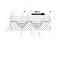
- a large oil film pressure acts on the flat sliding surface 3 as shown in FIG.
- the annealed portion 6 is pressed and deformed into a concave shape with respect to the quenched portion 7 to form a dotted or linear concave portion 6A on the surface thereof.
- Reference numeral 9 denotes a mating sliding surface such as a swash plate.
- the concave portion 6A functions as an oil sump or an oil passage depending on its shape, and the seizure resistance of the hemispherical shoe 1 can be remarkably improved by the concave portion 6A as will be shown in a later test result.
- the concave portion 6A is formed by pressing and deforming the annealed portion 6 into a concave shape. Therefore, even if the flat sliding surface 3, that is, the entire quenching portion 7 or the annealed portion 6, is worn, it is not lost. The seizure resistance can be maintained for a long time. Further, even when the flat sliding surface 3 is at a high temperature, it is not adversely affected thereby, and excellent seizure resistance can be ensured even at a high temperature.
- FIG. 5 shows a second embodiment of the present invention.
- the annealed portion 6 and the quenched portion 7 are polished flat by lapping or the like.
- the surface of the annealed portion 6 is further formed in a concave shape by buffing or the like, and the recess 6B is formed in advance on the surface of the annealed portion 6.
- a recess 6A is formed on the surface.
- the recess 6B can be used as an oil reservoir or an oil passage before a large oil film pressure is applied.
- the depth of the oil reservoir 6A is preferably formed to be about 1.0 ⁇ m.
- a part of the quenched flat sliding surface 3A is annealed in a dotted or linear manner at a lower temperature than in the case of quenching.
- the part 6 is formed (see FIG. 2B), quenching is performed depending on the heating conditions at that time, and as shown in FIG. May remain. Since the remaining hardened portion 8 remains due to the high temperature and rapid cooling of the central portion when forming the annealed portion 6, it remains like a floating island in the central portion of the annealed portion 6, and this remaining hardened portion 8 is not continuously formed in the quenching part 7 of the flat sliding surface 3 which is a base material.
- the said remaining hardened part 8 is unnecessary as this invention, and remains in the state which protruded from the surface of 3 A of flat-shaped sliding surfaces, the said annealed part 6 and the hardened part 7 are made by lapping etc. It is desirable to remove it when polishing flatly (see FIGS. 6B and 6C).
- annealing is performed by polishing, buffing, or the like.
- the remaining quenched portion 8 may be removed by forming the surface of the portion 6 in a concave shape (FIG. 7C).
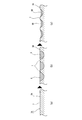
- FIG. 8 shows that the entire surface of the flat sliding surface 3 ⁇ / b> A is flat and smooth together with the annealing portion 6 and the quenching portion 7 including the remaining quenching portion 8 with the quenching portion 8 remaining in the central portion of the annealing portion 6. Polished. That is, after forming the annealed portion 6 in which the quenched portion 8 remains by annealing (FIG. 8B), the surface of the flat sliding surface 3A is processed to be smooth by polishing, buffing, or the like (FIG. 8). (C)).
- the remaining hardened portion 8 protrudes from the surface of the flat sliding surface 3 ⁇ / b> A formed by the annealed portion 6 and the hardened portion 7. Then, the surface of the flat sliding surface 3A including the remaining hardened portion 8 is polished flat by polishing such as barrel polishing for a relatively long time (FIG. 8D). In this way, if the entire surface of the flat sliding surface 3A including the remaining quenched portion 8 is formed flat, the remaining quenched portion 8 remains in the central portion of the annealed portion 6, so FIG.
- FIGS. 10A to 10C show the same manufacturing process as FIGS. 8A to 8C, and the surface of the flat sliding surface 3A is made smooth by polishing or buffing.
- the entire hemispherical shoe material 1A is subjected to low temperature tempering.
- the entire hemispherical shoe material 1A is held at, for example, 150 ° C. for 1 to 1.5 hours, and then cooled.
- the tetragonal martensite in the remaining quenched portion 8 changes to a tempered martensite structure in which cubic martensite and carbide are mixed.
- the concave portion 6 ⁇ / b> B may be formed in advance on the surface of the annealed portion 6.
- the remaining quenched portion 8 is formed from the surface of the flat sliding surface 3A formed by the annealed portion 6 and the quenched portion 7 as necessary. It may be left protruding. That is, after forming the annealed portion 6 where the quenched portion 8 remains by annealing (FIG. 8B), the surface of the flat sliding surface 3A is processed to be smooth by polishing or buffing (FIG. 8). 8 (c)), the remaining quenched portion 8 may be left protruding from the surface of the flat sliding surface 3A formed by the annealed portion 6 and the quenched portion 7.
- the protrusion height of the remaining quenched portion 8 is slight, when a large oil film pressure acts on the surface of the annealed portion 6 and a recess is formed on the surface of the annealed portion 6, The remaining quenched portion 8 can be retracted from the entire surface of the flat sliding surface 3A. Even if the residual quenching portion 8 is in sliding contact with the mating sliding surface, the concave portion 6A formed on the surface of the annealed portion 6 can be used as an oil sump or oil passage, and the residual quenching portion Since the hardness of 8 is large, the seizure resistance is not greatly reduced, and good seizure resistance can be ensured.
- FIG. 11 is explanatory drawing explaining the effect of the product of this invention by simulation.
- a point-like annealed portion 6 having a diameter of 0.9 mm is formed on a hardened material 1A having a hardness of Hv750.
- the annealed portion 6 is formed in a hemispherical shape in the material 1A and has a depth of 100 ⁇ m.
- a residual quenched portion 8 remains in the center of the surface of the annealed portion 6, and this remaining quenched portion 8 is formed in a semispherical shape in the annealed portion 6 and has a diameter of 0.3 mm and a depth of 50 ⁇ m. It has become.
- the surfaces of the quenched material 1A, the annealed portion 6 and the remaining quenched portion 8, that is, the entire surface of the flat sliding surface 3A are formed flat.
- a pressure of 50 MPa that can be generated between the hemispherical shoe and the swash plate in the car air conditioner compressor is applied to the sliding surface of the product of the present invention having the above-described configuration, as shown in FIG.
- a concave portion 6A is formed on the surface thereof, and the depth H of the concave portion 6A is 0.01 ⁇ m.
- the surface of the remaining hardened portion 8 is formed in advance so as to coincide with the entire surface of the flat sliding surface 3A, so that the flat sliding surface is formed along with the concave deformation of the annealed portion 6.
- the surface of the remaining hardened portion 8 is formed in advance so as to coincide with the entire surface of the flat sliding surface 3A, so that the flat sliding surface is formed along with the concave deformation of the annealed portion 6.
- FIG. 12 shows test results for seizure resistance performed on the above-described product of the present invention and the comparative product.
- a comparative product a material in which the sliding surface 3A of the hardened material 1A having a hardness Hv750 is simply formed flat is used.
- the test conditions are as follows. "Test conditions" Atmosphere: Car air compressor suction refrigerant atmosphere Refrigerant: R134a Oil: Refrigerator oil Rotation speed: 7200 rpm
- Counterpart High-strength brass swash plate Load: Increased by 2.0 MPa every 15 minutes from 4.8 MPa Seizure judgment: When the rotational drive torque of the swash plate exceeds 1.0 kg ⁇ m
- the comparative product caused seizure at 6.8 MPa, but the product of the present invention did not cause seizure even when it exceeded 16 MPa. Thereby, it can be understood that the product of the present invention has high seizure resistance performance compared to the comparative product.
- the hemispherical shoe 1 is exemplified as the sliding member.
- the present invention is not limited to this, and the present invention can be applied to various sliding members.
- the annealing part 6 was formed in the flat sliding surface 3 of the hemispherical shoe 1, it can also be formed in the hemispherical sliding surface 2.
Landscapes
- Engineering & Computer Science (AREA)
- Chemical & Material Sciences (AREA)
- Mechanical Engineering (AREA)
- General Engineering & Computer Science (AREA)
- Crystallography & Structural Chemistry (AREA)
- Thermal Sciences (AREA)
- Physics & Mathematics (AREA)
- Materials Engineering (AREA)
- Metallurgy (AREA)
- Organic Chemistry (AREA)
- Oil, Petroleum & Natural Gas (AREA)
- Manufacturing & Machinery (AREA)
- Compressors, Vaccum Pumps And Other Relevant Systems (AREA)
- Heat Treatment Of Articles (AREA)
- Sliding-Contact Bearings (AREA)
Abstract
Description
この摺動部材においては、直接焼き入れされて硬質となった直接焼入れ部分の凸部と、油溜りや油流通路として利用することができる非直接焼入れ部分の凹部とによって、優れた耐焼付性を確保することができる。
また、上記凸部が摩耗しなくても、過酷な使用などにより摺動面が高温となった場合には、直接焼入れされている上記凸部が熱収縮して摺動面が平坦となる危険性があることが判明した。
本発明はそのような事情に鑑み、高い耐焼付性が要求される半球状シュー等の摺動部材について、長期間使用しても、或いは摺動面が高温となったような場合でも、優れた耐焼付性を確保することができる摺動部材とその製造方法を提供するものである。
上記摺動部材の少なくとも上記摺動面を焼入れして焼入れ部を形成するとともに、焼入れされた摺動面の一部を部分的に焼鈍して焼鈍部を形成し、この焼鈍部は、上記摺動面に油膜圧力が作用した際に、その表面が凹状となるように押圧変形可能であることを特徴とするものである。
また請求項10の発明は、相手材と摺動する摺動面を有する摺動部材の製造方法において、
上記摺動部材の少なくとも上記摺動面の全域を焼入れして焼入れ部を形成した後に、上記焼入れされた摺動面の一部を部分的に焼鈍して焼鈍部を形成し、さらに上記焼入れ部の表面と焼鈍部の表面とを平坦に形成することを特徴とするものである。
また本発明においては、上述した従来の0.1~数μmという極めて小さな凸部によって耐焼付性を確保するようにしたものではないので、その凸部の摩耗による耐焼付性の低下といった問題や、凸部の熱収縮による耐焼付性の低下といった問題が発生することがなく、したがって長期間使用しても、或いは摺動面が高温となったような場合でも、優れた耐焼付性を確保することができるようになる。
上記半球状シュー1は、半球状をした摺動面2と端面側の平坦な摺動面3とを備えており、半球状摺動面2が上記ピストンの半球状の凹部に摺接するとともに、平坦状摺動面3が斜板に摺接するようになっている。
なお、上記素材としては焼入れ可能な鉄系材料や、アルミシリコン合金、銅合金、純チタンやチタン合金などを用いることができ、表面の弾性変形に追従可能であれば上記素材に表面処理を施しても良い。また斜板などの相手材としては、高力黄銅、鉄系基材、鉄系基材+銅合金、アルミシリコン合金、鉄系基材+アルミシリコン合金、鉄系基材+樹脂コーティング等の表面処理、であることが好ましい。
この後、上記焼鈍部6と焼入れ部7とがラップ加工やバレル加工などにより平滑かつ平坦に研磨されて、焼鈍部6と焼入れ部7とを有する平坦状摺動面3が完成される。
さらに点状の焼鈍部6としては、図3(g)に示すように、まさに点状に形成することができ、また上述した種々の形状を2つ以上組み合わせたものであってもよい。
レーザを用いた焼鈍の場合には、レーザの照射によってその照射部を加熱し、その後空冷によって常温まで冷却することによって行うことができる。加熱温度は素材のそれまでの熱履歴によって異なる。なお、レーザによって鋼を焼き入れる場合には、レーザの照射によってその照射部を鋼のマルテンサイトスタート点(約727℃)以上に加熱する必要があるが、焼鈍の場合には焼き入れの場合に比較して低い温度の加熱となることは勿論である。
上記凹部6Aはその形状によって油溜りや油通路として機能するようになり、後の試験結果で示すように、この凹部6Aによって半球状シュー1の耐焼付性を著しく向上させることができる。
上記凹部6Aは、焼鈍部6が凹状に押圧変形されることによって形成されるので、平坦状摺動面3すなわち焼入れ部7や焼鈍部6の全面が摩耗されても無くなることはなく、したがって良好な耐焼付性を長期間維持することができる。また平坦状摺動面3が高温となったような場合でも、それによる悪影響を受けることがなく、高温状態においても優れた耐焼付性を確保することができる。
上述したように、焼鈍部6の表面が平坦であっても、該焼鈍部6の表面に大きな油膜圧力が作用すればその表面に凹部6Aが形成されるようになるが、本実施例のように予め凹部6Bを形成しておけば、大きな油膜圧力が作用する以前から該凹部6Bは油溜りや油通路として利用することができるようになる。
上記油溜り部6Aの深さは、1.0μm程度となるように形成することが好ましい。
この残存焼入れ部8は、焼鈍部6を形成する際の中央部分の高温化と急冷によって残存してしまうので、焼鈍部6の中央部分に浮島のように残存するようになり、この残存焼入れ部8が母材である平坦状摺動面3の焼入れ部7に連続して形成されることはない。
そして上記残存焼入れ部8は、本発明としては不要なものであり、また平坦状摺動面3Aの表面から突出した状態で残存しまうので、上記焼鈍部6と焼入れ部7とをラップ加工などにより平坦に研磨する際に、除去することが望ましい(図6(b)、(c)参照)。
或いは図7に示すように、残存焼入れ部8の深さや大きさによっては、焼鈍によって焼入れ部8が残存する焼鈍部6を形成した後に(図7(b))、研磨やバフ加工などにより焼鈍部6の表面を凹状に形成することによって上記残存焼入れ部8を除去してもよい(図7(c))。
図8は焼鈍部6の中央部分に焼入れ部8を残存させたまま、該残存焼入れ部8を含めて、焼鈍部6と焼入れ部7と共に平坦状摺動面3Aの全体の表面を平坦かつ平滑に研磨したものである。
すなわち、焼鈍によって焼入れ部8が残存する焼鈍部6を形成した後に(図8(b))、研磨やバフ加工などにより平坦状摺動面3Aの表面が滑らかとなるように加工する(図8(c))。この段階では、残存焼入れ部8は焼鈍部6と焼入れ部7とから形成される平坦状摺動面3Aの表面から突出している。
そして次に、相対的に長時間のバレル研磨などの研磨により、残存焼入れ部8を含めて平坦状摺動面3Aの表面を平坦に研磨する(図8(d))。
このように、残存焼入れ部8を含めて平坦状摺動面3Aの全体の表面を平坦に形成すれば、該残存焼入れ部8は焼鈍部6の中央部分に残存しているので、図9に示すように、焼鈍部6の表面に大きな油膜圧力が作用して該焼鈍部6の表面に凹部6Aが形成された際に、平坦状摺動面3Aの全体の表面から退没するようになる。
したがって上記残存焼入れ部8が相手側摺動面9に接触することはなく、図4で説明したのと同等の作用効果を得ることができる。
図10(a)~(c)は、図8(a)~(c)と同一の製造工程を示しており、研磨やバフ加工などにより平坦状摺動面3Aの表面が滑らかとなるように加工した後に(図10(c))、半球状シュー素材1Aの全体に低温焼き戻しを施している。
この低温焼き戻し工程では、半球状シュー素材1Aの全体を例えば150℃で1~1.5時間保持し、その後、除冷する。これにより、残存焼入れ部8における正方晶のマルテンサイトは、立方晶のマルテンサイトと炭化物の混ざった焼戻しマルテンサイト組織に変化する。すると、残存焼入れ部8の収縮が生じて、該残存焼入れ部8の表面が平坦状摺動面3Aの全体の表面から退没するようになる(図10(d))。
このように、残存焼入れ部8の表面を凹ませて凹部6Cを形成しておけば、大きな油膜圧力が作用する以前から該凹部6Cを油溜りや油通路として利用することができるようになる。そしてこのとき、図5について説明したように、焼鈍部6の表面についても、予め凹部6Bを形成してもよい。
すなわち、焼鈍によって焼入れ部8が残存する焼鈍部6を形成した後に(図8(b))、研磨やバフ加工などにより平坦状摺動面3Aの表面が滑らかとなるように加工して(図8(c))、残存焼入れ部8を焼鈍部6と焼入れ部7とから形成される平坦状摺動面3Aの表面から突出した状態のままとしても良い。
この場合であっても、残存焼入れ部8の突出高さが僅かであれば、焼鈍部6の表面に大きな油膜圧力が作用して該焼鈍部6の表面に凹部が形成された際に、該残存焼入れ部8を平坦状摺動面3Aの全体の表面から退没させることが可能である。
仮に残存焼入れ部8が相手側摺動面に摺接したとしても、焼鈍部6の表面に形成される凹部6Aによって該凹部を油溜りや油通路として利用することができるとともに、上記残存焼入れ部8の硬度は大きいので、耐焼付性が大きく低下することはなく、良好な耐焼付性を確保することができる。
図11に示すように、このシミュレーションでは、本発明品として、硬さHv750の焼入れした素材1Aに、直径0.9mmの点状の焼鈍部6を形成してある。この焼鈍部6は素材1A内に半球状に形成されており、その深さは100μmとなっている。
また、焼鈍部6の表面の中央に残存焼入れ部8が残存しており、この残存焼入れ部8は焼鈍部6内に半球状に形成されて、その直径は0.3mm、深さは50μmとなっている。そして焼入れした素材1Aと焼鈍部6と残存焼入れ部8の表面、すなわち平坦状摺動面3Aの全体の表面は、平坦に形成してある。
上記構成を有する本発明品の摺動表面に、カーエアコンコンプレッサ内の半球状シューと斜板との間で発生し得る50MPaという圧力を加えた際には、図9で示されているように、焼鈍部6の凹状の変形によりその表面に凹部6Aが形成されるようになり、その凹部6Aの深さHは0.01μmであった。
このとき、残存焼入れ部8の表面は、予め平坦状摺動面3Aの全体の表面に一致させて平坦に形成してあるので、焼鈍部6の凹状の変形に伴って上記平坦状摺動面3Aの全体の表面から退没するようになり、相手側摺動面9に当接することはない。
この試験条件は、次の通りである。
「試験条件」
雰囲気:カーエアコンプレッサ吸入冷媒雰囲気
冷媒:R134a
オイル:冷凍機油
回転数:7200rpm
相手材:高力黄銅製斜板
荷重:4.8MPaから15分毎に2.0MPaずつ増大
焼付き判定:斜板の回転駆動トルクが1.0kg・mを越えた時点
これにより、本発明品は比較品に対して高い耐焼付性能を有していることが理解できる。
2 半球状摺動面 3、3A 平坦状摺動面
6 焼鈍部 6A、6B、6C 凹部
7 焼入れ部 8 残存焼入れ部
Claims (14)
- 相手材と摺動する摺動面を有する摺動部材において、
上記摺動部材の少なくとも上記摺動面を焼入れして焼入れ部を形成するとともに、焼入れされた摺動面の一部を部分的に焼鈍して焼鈍部を形成し、この焼鈍部は、上記摺動面に油膜圧力が作用した際に、その表面が凹状となるように押圧変形可能であることを特徴とする摺動部材。 - 上記焼入れ部の表面と焼鈍部の表面とが平坦に形成されて、該焼入れ部と焼鈍部とが形成された摺動面全体が平坦に形成されていることを特徴とする請求項1に記載の摺動部材。
- 上記焼入れ部の表面が平坦に形成されるとともに、上記焼鈍部の表面が凹状に形成されていることを特徴とする請求項1に記載の摺動部材。
- 上記焼鈍部の中央部分に、焼入れ部が残存していることを特徴とする請求項1ないし請求項3のいずれかに記載の摺動部材。
- 上記焼鈍部の中央部分に残存する残存焼入れ部の表面が平坦に形成されていることを特徴とする請求項4に記載の摺動部材。
- 上記焼鈍部の中央部分に残存する残存焼入れ部の表面が凹状に形成されていることを特徴とする請求項4に記載の摺動部材。
- 上記焼鈍部の中央部分に残存する残存焼入れ部の表面が凸状に形成されていることを特徴とする請求項4に記載の摺動部材。
- 上記焼鈍部は、平行な直線状、同心円状、らせん状、渦巻状、格子状、放射状、小さな円を点在させたもの、点状のいずれか、又はそれらを2つ以上組み合わせたものであることを特徴とする請求項1ないし請求項7のいずれかに記載の摺動部材。
- 上記摺動部材は半球状のシューであって、該シューは半球状の摺動面と平坦状の摺動面とを有し、平坦状の摺動面に上記焼入れ部と焼鈍部とが形成されていることを特徴とする請求項1ないし請求項8のいずれかに記載の摺動部材。
- 相手材と摺動する摺動面を有する摺動部材の製造方法において、
上記摺動部材の少なくとも上記摺動面の全域を焼入れして焼入れ部を形成した後に、上記焼入れされた摺動面の一部を部分的に焼鈍して焼鈍部を形成し、さらに上記焼入れ部の表面と焼鈍部の表面とを平坦に形成することを特徴とする摺動部材の製造方法。 - 上記焼鈍部の中央部分に焼入れ部が残存しており、上記焼入れ部の表面と焼鈍部の表面とを平坦に形成する際に、該焼鈍部の中央部分に残存した残存焼入れ部の表面も平坦に形成することを特徴とする請求項10に記載の摺動部材の製造方法。
- 上記残存焼入れ部を平坦に形成した後に、摺動部材に低温焼き戻しを施して、上記残存焼入れ部の表面を凹状に形成することを特徴とする請求項11に記載の摺動部材の製造方法。
- 上記焼鈍部を平坦に形成した後に、該焼鈍部の表面を凹状に形成することを特徴とする請求項10ないし請求項12のいずれかに記載の摺動部材の製造方法。
- 上記焼鈍部は、平行な直線状、同心円状、らせん状、渦巻状、格子状、放射状、小さな円を点在させたもの、点状のいずれか、又はそれらを2つ以上組み合わせたものであることを特徴とする請求項10ないし請求項14のいずれかに記載の摺動部材の製造方法。
Priority Applications (4)
| Application Number | Priority Date | Filing Date | Title |
|---|---|---|---|
| CN201180036438.XA CN103026086B (zh) | 2010-07-27 | 2011-03-22 | 滑动构件及其制造方法 |
| KR1020127033968A KR101408065B1 (ko) | 2010-07-27 | 2011-03-22 | 슬라이딩 부재와 그 제조 방법 |
| US13/704,092 US8770842B2 (en) | 2010-07-27 | 2011-03-22 | Sliding member and manufacturing method thereof |
| EP11812118.5A EP2600016B1 (en) | 2010-07-27 | 2011-03-22 | Sliding member and method for producing same |
Applications Claiming Priority (2)
| Application Number | Priority Date | Filing Date | Title |
|---|---|---|---|
| JP2010167816A JP5472630B2 (ja) | 2010-07-27 | 2010-07-27 | 摺動部材とその製造方法 |
| JP2010-167816 | 2010-07-27 |
Publications (1)
| Publication Number | Publication Date |
|---|---|
| WO2012014522A1 true WO2012014522A1 (ja) | 2012-02-02 |
Family
ID=45529746
Family Applications (1)
| Application Number | Title | Priority Date | Filing Date |
|---|---|---|---|
| PCT/JP2011/056729 Ceased WO2012014522A1 (ja) | 2010-07-27 | 2011-03-22 | 摺動部材とその製造方法 |
Country Status (6)
| Country | Link |
|---|---|
| US (1) | US8770842B2 (ja) |
| EP (1) | EP2600016B1 (ja) |
| JP (1) | JP5472630B2 (ja) |
| KR (1) | KR101408065B1 (ja) |
| CN (1) | CN103026086B (ja) |
| WO (1) | WO2012014522A1 (ja) |
Families Citing this family (8)
| Publication number | Priority date | Publication date | Assignee | Title |
|---|---|---|---|---|
| ES2475141T3 (es) * | 2011-12-22 | 2014-07-10 | Imo Holding Gmbh | Disposición de rodamientos con zonas de temple inclinadas |
| JP5731991B2 (ja) * | 2012-01-20 | 2015-06-10 | 大豊工業株式会社 | 摺動部材 |
| JP6487276B2 (ja) * | 2015-06-01 | 2019-03-20 | 株式会社ジェイテクト | 摺動部材の製造方法およびクラッチプレートの製造方法 |
| ES2703824T3 (es) * | 2015-12-03 | 2019-03-12 | Flender Graffenstaden S A S | Cojinete hidrostático con función hidrodinámica |
| CN106195017A (zh) * | 2016-08-08 | 2016-12-07 | 洛阳轴研科技股份有限公司 | 一种三排滚子转盘轴承的软带硬化方法 |
| JP7120054B2 (ja) * | 2019-01-29 | 2022-08-17 | トヨタ自動車株式会社 | 車両用構造体及び車両用鋼板の強化方法 |
| JP7762589B2 (ja) * | 2022-01-31 | 2025-10-30 | 住友重機械工業株式会社 | 装置及び製造方法 |
| CN117363842A (zh) * | 2023-10-11 | 2024-01-09 | 青岛征和工业股份有限公司 | 一种点阵式激光淬火工艺 |
Citations (8)
| Publication number | Priority date | Publication date | Assignee | Title |
|---|---|---|---|---|
| JPH02173212A (ja) * | 1988-12-26 | 1990-07-04 | Hitachi Ltd | 摺動材及びその表面処理方法 |
| JPH07113421A (ja) * | 1992-03-13 | 1995-05-02 | Tone Corp | 耐摩耗性と潤滑性に優れた摺動部材およびその製造方 法 |
| JP2003001364A (ja) * | 2001-06-15 | 2003-01-07 | Toyota Industries Corp | 圧縮機用シューの製造方法 |
| JP2006070838A (ja) | 2004-09-03 | 2006-03-16 | Taiho Kogyo Co Ltd | 摺動部材 |
| JP2006183627A (ja) * | 2004-12-28 | 2006-07-13 | Taiho Kogyo Co Ltd | シュー |
| JP2006194220A (ja) * | 2005-01-17 | 2006-07-27 | Taiho Kogyo Co Ltd | 摺動部材の製造方法 |
| JP2006207503A (ja) * | 2005-01-28 | 2006-08-10 | Taiho Kogyo Co Ltd | 摺動部材の製造方法。 |
| WO2006117901A1 (ja) * | 2005-04-27 | 2006-11-09 | Taiho Kogyo Co., Ltd. | 摺動装置 |
Family Cites Families (11)
| Publication number | Priority date | Publication date | Assignee | Title |
|---|---|---|---|---|
| DE2353928A1 (de) * | 1973-10-27 | 1975-05-15 | Chr Mann Maschinenfabrik | Verfahren zur verbesserung der gleiteigenschaften gehaerteter stahlteile |
| JPS62237111A (ja) * | 1986-04-07 | 1987-10-17 | Hitachi Ltd | ジヤ−ナル軸受 |
| US6739238B2 (en) * | 2000-11-20 | 2004-05-25 | Nissan Motor Co., Ltd. | Sliding structure for a reciprocating internal combustion engine and a reciprocating internal combustion engine using the sliding structure |
| JP2002180964A (ja) * | 2000-12-12 | 2002-06-26 | Toyota Industries Corp | 圧縮機の摺動部品及び圧縮機 |
| JP2002332959A (ja) * | 2001-05-10 | 2002-11-22 | Toyota Industries Corp | 球冠状シューおよびそれが配設された斜板式圧縮機 |
| JP4520223B2 (ja) * | 2004-06-16 | 2010-08-04 | 本田技研工業株式会社 | 窒化処理摺動面の形成方法 |
| JP3904011B2 (ja) * | 2004-09-03 | 2007-04-11 | 大豊工業株式会社 | 半球状シューの製造方法 |
| JP4817039B2 (ja) * | 2004-11-11 | 2011-11-16 | 大豊工業株式会社 | 摺動装置 |
| CN100451332C (zh) * | 2004-11-11 | 2009-01-14 | 大丰工业株式会社 | 滑动装置 |
| KR100870675B1 (ko) * | 2004-12-28 | 2008-11-26 | 다이호 고교 가부시키가이샤 | 슈 |
| EP1854897A4 (en) * | 2005-01-17 | 2012-04-25 | Taiho Kogyo Co Ltd | METHOD FOR PRODUCING A SLIDE ELEMENT |
-
2010
- 2010-07-27 JP JP2010167816A patent/JP5472630B2/ja not_active Expired - Fee Related
-
2011
- 2011-03-22 WO PCT/JP2011/056729 patent/WO2012014522A1/ja not_active Ceased
- 2011-03-22 KR KR1020127033968A patent/KR101408065B1/ko not_active Expired - Fee Related
- 2011-03-22 CN CN201180036438.XA patent/CN103026086B/zh not_active Expired - Fee Related
- 2011-03-22 EP EP11812118.5A patent/EP2600016B1/en active Active
- 2011-03-22 US US13/704,092 patent/US8770842B2/en not_active Expired - Fee Related
Patent Citations (8)
| Publication number | Priority date | Publication date | Assignee | Title |
|---|---|---|---|---|
| JPH02173212A (ja) * | 1988-12-26 | 1990-07-04 | Hitachi Ltd | 摺動材及びその表面処理方法 |
| JPH07113421A (ja) * | 1992-03-13 | 1995-05-02 | Tone Corp | 耐摩耗性と潤滑性に優れた摺動部材およびその製造方 法 |
| JP2003001364A (ja) * | 2001-06-15 | 2003-01-07 | Toyota Industries Corp | 圧縮機用シューの製造方法 |
| JP2006070838A (ja) | 2004-09-03 | 2006-03-16 | Taiho Kogyo Co Ltd | 摺動部材 |
| JP2006183627A (ja) * | 2004-12-28 | 2006-07-13 | Taiho Kogyo Co Ltd | シュー |
| JP2006194220A (ja) * | 2005-01-17 | 2006-07-27 | Taiho Kogyo Co Ltd | 摺動部材の製造方法 |
| JP2006207503A (ja) * | 2005-01-28 | 2006-08-10 | Taiho Kogyo Co Ltd | 摺動部材の製造方法。 |
| WO2006117901A1 (ja) * | 2005-04-27 | 2006-11-09 | Taiho Kogyo Co., Ltd. | 摺動装置 |
Also Published As
| Publication number | Publication date |
|---|---|
| EP2600016A1 (en) | 2013-06-05 |
| EP2600016B1 (en) | 2020-12-23 |
| CN103026086B (zh) | 2015-05-20 |
| KR20130018952A (ko) | 2013-02-25 |
| US20130089282A1 (en) | 2013-04-11 |
| US8770842B2 (en) | 2014-07-08 |
| JP5472630B2 (ja) | 2014-04-16 |
| EP2600016A4 (en) | 2017-01-25 |
| CN103026086A (zh) | 2013-04-03 |
| KR101408065B1 (ko) | 2014-06-18 |
| JP2012026538A (ja) | 2012-02-09 |
Similar Documents
| Publication | Publication Date | Title |
|---|---|---|
| JP5472630B2 (ja) | 摺動部材とその製造方法 | |
| CN106111874B (zh) | 一种机动车用轴承锻件的加工方法 | |
| JP2010065280A (ja) | 熱間加工用金型 | |
| KR101910467B1 (ko) | 국부가열 및 초음파 나노크리스탈 표면개질을 이용한 표면처리방법 | |
| WO2012176834A1 (ja) | 圧力リング及びその製造方法 | |
| CN102380920B (zh) | 一种气门成型模具的加工方法 | |
| CN105983818A (zh) | 一种定位环加工工艺 | |
| JP4817039B2 (ja) | 摺動装置 | |
| CN100504065C (zh) | 滑动构件 | |
| CN101006273B (zh) | 半球状滑履及其制造方法 | |
| WO2015056315A1 (ja) | 摺動部品、摺動部品の製造方法および摺動部品の製造装置 | |
| CN105414906A (zh) | 高强度、高精度轮毂轴加工方法 | |
| CN105563032B (zh) | 应用双金属管料制造复合轴承的方法 | |
| TWI763428B (zh) | 應用於諧波減速器之剛輪、其製造方法及諧波減速器 | |
| JP2007232033A (ja) | 固定式等速自在継手及びその製造方法 | |
| JP2006275034A (ja) | チタン合金製バルブリフタ及びその製造方法 | |
| JP2006291239A (ja) | 汎用小型ベアリングのベアリング内外輪用の高炭素クロム軸受鋼鍛造素形材の製造方法および転動疲労寿命に優れた軌道面と高靱性の軌道保持部を有するベアリング内外輪 | |
| KR101877715B1 (ko) | 밸브 플레이트용 금속소재의 제조 방법 | |
| JP6367476B2 (ja) | 摺動部品およびその製造方法 | |
| CN105880928A (zh) | 一种定位环加工工艺 | |
| CN102359495A (zh) | 一种轴承内外圈的制作方法 | |
| JP2004143536A (ja) | 転がり摺動部材の製造方法 | |
| JP2007064292A (ja) | 偏心スラスト玉軸受 | |
| JP2021011608A (ja) | 軌道輪及び転がり軸受 | |
| JP2007064293A (ja) | 偏心スラスト玉軸受 |
Legal Events
| Date | Code | Title | Description |
|---|---|---|---|
| WWE | Wipo information: entry into national phase |
Ref document number: 201180036438.X Country of ref document: CN |
|
| 121 | Ep: the epo has been informed by wipo that ep was designated in this application |
Ref document number: 11812118 Country of ref document: EP Kind code of ref document: A1 |
|
| WWE | Wipo information: entry into national phase |
Ref document number: 13704092 Country of ref document: US |
|
| ENP | Entry into the national phase |
Ref document number: 20127033968 Country of ref document: KR Kind code of ref document: A |
|
| WWE | Wipo information: entry into national phase |
Ref document number: 2011812118 Country of ref document: EP |
|
| NENP | Non-entry into the national phase |
Ref country code: DE |
|
| REG | Reference to national code |
Ref country code: BR Ref legal event code: B01A Ref document number: 112012033322 Country of ref document: BR |
|
| REG | Reference to national code |
Ref country code: BR Ref legal event code: B01E Ref document number: 112012033322 Country of ref document: BR |
|
| ENP | Entry into the national phase |
Ref document number: 112012033322 Country of ref document: BR Kind code of ref document: A2 Effective date: 20121227 |