WO2012014691A1 - Dispositif de biomesure, procédé de biomesure, programme de commande pour un dispositif de biomesure, et support d'enregistrement avec ledit programme de commande enregistré sur celui-ci - Google Patents
Dispositif de biomesure, procédé de biomesure, programme de commande pour un dispositif de biomesure, et support d'enregistrement avec ledit programme de commande enregistré sur celui-ci Download PDFInfo
- Publication number
- WO2012014691A1 WO2012014691A1 PCT/JP2011/066054 JP2011066054W WO2012014691A1 WO 2012014691 A1 WO2012014691 A1 WO 2012014691A1 JP 2011066054 W JP2011066054 W JP 2011066054W WO 2012014691 A1 WO2012014691 A1 WO 2012014691A1
- Authority
- WO
- WIPO (PCT)
- Prior art keywords
- measurement
- parameter
- information
- unit
- biological
- Prior art date
- Legal status (The legal status is an assumption and is not a legal conclusion. Google has not performed a legal analysis and makes no representation as to the accuracy of the status listed.)
- Ceased
Links
Images
















Classifications
-
- A—HUMAN NECESSITIES
- A61—MEDICAL OR VETERINARY SCIENCE; HYGIENE
- A61B—DIAGNOSIS; SURGERY; IDENTIFICATION
- A61B5/00—Measuring for diagnostic purposes; Identification of persons
- A61B5/145—Measuring characteristics of blood in vivo, e.g. gas concentration or pH-value ; Measuring characteristics of body fluids or tissues, e.g. interstitial fluid or cerebral tissue
- A61B5/1455—Measuring characteristics of blood in vivo, e.g. gas concentration or pH-value ; Measuring characteristics of body fluids or tissues, e.g. interstitial fluid or cerebral tissue using optical sensors, e.g. spectral photometrical oximeters
- A61B5/14551—Measuring characteristics of blood in vivo, e.g. gas concentration or pH-value ; Measuring characteristics of body fluids or tissues, e.g. interstitial fluid or cerebral tissue using optical sensors, e.g. spectral photometrical oximeters for measuring blood gases
-
- G—PHYSICS
- G16—INFORMATION AND COMMUNICATION TECHNOLOGY [ICT] SPECIALLY ADAPTED FOR SPECIFIC APPLICATION FIELDS
- G16H—HEALTHCARE INFORMATICS, i.e. INFORMATION AND COMMUNICATION TECHNOLOGY [ICT] SPECIALLY ADAPTED FOR THE HANDLING OR PROCESSING OF MEDICAL OR HEALTHCARE DATA
- G16H50/00—ICT specially adapted for medical diagnosis, medical simulation or medical data mining; ICT specially adapted for detecting, monitoring or modelling epidemics or pandemics
- G16H50/30—ICT specially adapted for medical diagnosis, medical simulation or medical data mining; ICT specially adapted for detecting, monitoring or modelling epidemics or pandemics for calculating health indices; for individual health risk assessment
-
- A—HUMAN NECESSITIES
- A61—MEDICAL OR VETERINARY SCIENCE; HYGIENE
- A61B—DIAGNOSIS; SURGERY; IDENTIFICATION
- A61B5/00—Measuring for diagnostic purposes; Identification of persons
- A61B5/01—Measuring temperature of body parts ; Diagnostic temperature sensing, e.g. for malignant or inflamed tissue
-
- A—HUMAN NECESSITIES
- A61—MEDICAL OR VETERINARY SCIENCE; HYGIENE
- A61B—DIAGNOSIS; SURGERY; IDENTIFICATION
- A61B5/00—Measuring for diagnostic purposes; Identification of persons
- A61B5/24—Detecting, measuring or recording bioelectric or biomagnetic signals of the body or parts thereof
- A61B5/316—Modalities, i.e. specific diagnostic methods
- A61B5/318—Heart-related electrical modalities, e.g. electrocardiography [ECG]
-
- A—HUMAN NECESSITIES
- A61—MEDICAL OR VETERINARY SCIENCE; HYGIENE
- A61B—DIAGNOSIS; SURGERY; IDENTIFICATION
- A61B5/00—Measuring for diagnostic purposes; Identification of persons
- A61B5/48—Other medical applications
- A61B5/4806—Sleep evaluation
- A61B5/4818—Sleep apnoea
-
- A—HUMAN NECESSITIES
- A61—MEDICAL OR VETERINARY SCIENCE; HYGIENE
- A61B—DIAGNOSIS; SURGERY; IDENTIFICATION
- A61B2562/00—Details of sensors; Constructional details of sensor housings or probes; Accessories for sensors
- A61B2562/02—Details of sensors specially adapted for in-vivo measurements
- A61B2562/0204—Acoustic sensors
-
- A—HUMAN NECESSITIES
- A61—MEDICAL OR VETERINARY SCIENCE; HYGIENE
- A61B—DIAGNOSIS; SURGERY; IDENTIFICATION
- A61B2562/00—Details of sensors; Constructional details of sensor housings or probes; Accessories for sensors
- A61B2562/02—Details of sensors specially adapted for in-vivo measurements
- A61B2562/0219—Inertial sensors, e.g. accelerometers, gyroscopes, tilt switches
Definitions
- the present invention relates to a living body measuring apparatus that measures the state of a living body.
- Patent Document 1 discloses a living body in which a sensor (sensor mounting head) is mounted on a user's body, and the main body measures a plurality of parameters (biological information) of the user based on signal information obtained from the sensor.
- An information measuring device is disclosed.
- This biological information measuring apparatus detects a mounting site of a mounted sensor, selects a parameter that can be measured at the detected mounting site, or amplifies a signal information signal output from the sensor according to the mounting site. Adjust the degree.
- a biological information measuring device with a wide range of use is realized without limiting the mounting site and application of the sensor.
- Patent Document 2 discloses a wireless biological information detection system that detects and collects continuous parameters (biological information) using a plurality of wireless biological information sensor modules regardless of time and place.
- this wireless biological information detection system the presence or absence of a physical abnormality is evaluated and determined by comparing the collected parameters with parameters from other sensor modules.
- cough symptoms have been conventionally diagnosed based on patient self-reports and have not been evaluated objectively.
- Patent Document 3 a detection device that accurately detects cough by detecting sound from the throat of a subject using a microphone and analyzing a frequency band included in the detected sound is disclosed. Proposed.
- Patent Document 4 discloses a cough detection device that detects a subject's voice with a microphone, detects a subject's body movement with an accelerometer, and detects cough based on the voice and body movement. .
- a pulse oximetry method or a flow sensor method is known as a simple inspection method for sleep apnea syndrome.
- the pulse oximetry method is a method for measuring the presence of apnea by measuring blood oxygen saturation (SpO 2 ) or pulse.
- SpO 2 blood oxygen saturation
- An example of such a method is disclosed in Patent Documents 5 and 6.
- breathing sounds, snoring sounds, body movements or postures are measured simultaneously with the blood oxygen saturation to improve the measurement accuracy.
- a simple inspection method using a flow sensor that measures the airflow in the mouth or nose is also a simple inspection method using a flow sensor that measures the airflow in the mouth or nose.
- apnea syndrome is displayed by displaying changes in the apnea index and changes in other related physiological indices (exercise, obesity information, blood pressure, etc.). The subjects are motivated to perform therapy to improve their symptoms.
- the present invention has been made in view of the above problems, and its purpose is to measure a state of a living body by a suitable method in accordance with the purpose of measurement and derive a more accurate measurement result.
- a biological measurement method, a control program for the biological measurement apparatus, and a recording medium on which the control program is recorded are recorded.
- the biometric apparatus of the present invention is a biometric apparatus that measures the state of a living body using biological signal information acquired from the living body, and is obtained based on the biological signal information.
- a measurement method storage unit that stores the parameter designation information to be associated with each other, and the measurement result deriving unit uses the parameter designated by the parameter designation information corresponding to the measurement item, and the measurement result of the measurement item It is characterized by deriving information.
- the biometric apparatus stores the measurement item and the parameter designation information in association with each other in the measurement method storage unit.
- the measurement item indicates the purpose of measurement that can be performed by the device itself (what kind of state of the living body is measured).
- the parameter designation information is information that designates a parameter used by the measurement result deriving unit to derive the measurement result information when performing the measurement related to the measurement item.
- the measurement result deriving means intends to perform the measurement related to a certain measurement item
- the measurement result information indicating the state of the living body is obtained using the parameter designated by the parameter designation information associated with the measurement item.
- the measurement result deriving unit may use one or a plurality of the above parameters, but among the parameters to be used, the biosignal information acquired from the living body is included.
- the biometric parameter obtained based on at least is included.
- the measurement result deriving means derives the measurement result information using the parameter associated with the measurement item.
- the parameters always include biological parameters of the living body. Therefore, since the state of the living body is measured using parameters suitable for the purpose according to the purpose of the measurement, it is possible to derive a more accurate measurement result.
- the biometric method of the present invention is a biometric method in a biometric apparatus that measures the state of a living body using biosignal information acquired from a living body. Is stored in association with measurement items that can be measured by the biological measurement apparatus and parameter designation information for designating one or more parameters used for measurement of the measurement items. At least one biological parameter obtained based on the signal information is specified, and the parameter specified by the parameter specifying information corresponding to the measurement item is specified, and the parameter specified in the specifying step is used. And deriving measurement result information indicating the state of the living body related to the measurement item.
- the biometric apparatus may be realized by a computer.
- a biometric apparatus control program for causing the biometric apparatus to be realized by a computer by operating the computer as each of the means, and A computer-readable recording medium on which is recorded also falls within the scope of the present invention.
- the biometric apparatus of the present invention is a biometric apparatus that measures the state of a living body using biological signal information acquired from the living body, and is obtained based on the biological signal information.
- a measurement method storage unit that stores the parameter designation information to be associated with each other, and the measurement result deriving unit uses the parameter designated by the parameter designation information corresponding to the measurement item, and the measurement result of the measurement item It is characterized by deriving information.
- the biometric method of the present invention is a biometric method in a biometric apparatus that measures the state of a living body using biosignal information acquired from a living body. Is stored in association with measurement items that can be measured by the biological measurement apparatus and parameter designation information for designating one or more parameters used for measurement of the measurement items. At least one biological parameter obtained based on the signal information is specified, and the parameter specified by the parameter specifying information corresponding to the measurement item is specified, and the parameter specified in the specifying step is used. And deriving measurement result information indicating the state of the living body related to the measurement item.
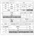
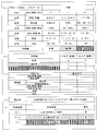
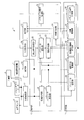
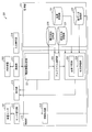
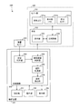
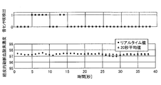
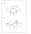
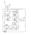
- FIG. 1 It is a block diagram which shows the principal part structure of the analyzer (biometric measuring apparatus) in embodiment of this invention. It is the schematic which shows the structure of the biometric system in embodiment of this invention. It is a figure which shows the data structure of the information memorize
- (A)-(d) is a figure which shows the specific example of an apnea degree calculation rule
- (e) is a figure which shows the specific example of the criteria information of apnea degree.
- (A)-(d) is a figure which shows the specific example of a sleep depth calculation rule
- (e) is a figure which shows the specific example of the criteria information on sleep depth.
- (A)-(d) is a figure which shows the specific example of the asthma severity calculation rule
- (e) is a figure which shows the specific example of the criteria information of asthma severity.
- (A)-(d) is a figure which shows the specific example of a heart activity level calculation rule
- (e) is a figure which shows the specific example of the criteria reference information of a heart activity level.
- (A)-(d) is a figure which shows the specific example of the digestive organ activity calculation rule
- (e) is a figure which shows the specific example of the criteria information of digestive organ activity.
- (A)-(d) is a figure which shows the specific example of a cardiovascular activity calculation rule
- (e) is a figure which shows the specific example of the criteria reference information of a cardiovascular activity.
- (A)-(d) is a figure which shows the specific example of a cough severity calculation rule
- (e) is a figure which shows the specific example of the criteria information of a cough severity. It is a figure which shows the example which displayed the measurement result obtained when the analysis apparatus performed the biometric process about measurement item "1: Apnea degree measurement”.
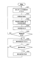
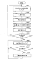
- FIG. 35 It is a flowchart which shows the flow of the biometric measurement process of the analyzer in one Embodiment of this invention.
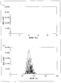
- A) And (b) is a figure which shows the waveform of the sound data extract
- A) And (b) is a figure which shows the frequency spectrum of the sound data obtained by applying the sound data shown to (a) and (b) of FIG. 35 to a fast Fourier transform (FFT) process.
- FFT fast Fourier transform
- A) and (b) are waveforms of sound data collected from an acoustic sensor or a sample of normal heart sounds stored in the sound source storage unit 232 when the wearing state is normal and good (improved).
- FIG. 39 It is a figure which shows the waveform of sound data which become.
- (A) And (b) is a figure which shows the frequency spectrum of the sound data obtained by applying the sound data shown to (a) and (b) of FIG. 37 to an FFT process.
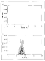
- (A) And (b) is a figure which shows the waveform of the sound data extract
- (A) And (b) is a figure which shows the frequency spectrum of the sound data obtained by applying the sound data shown to (a) and (b) of FIG. 39 to FFT processing. It is a block diagram which shows the principal part structure of the analyzer in other embodiment of this invention.
- Embodiment 1 ⁇ Embodiment 1-1 >> An embodiment of the present invention will be described below with reference to the drawings.
- the biometric apparatus of the present invention acquires biological signal information from a sensor or the like that senses the state of a living body, and measures various states and symptoms of the living body using parameters obtained therefrom.
- a living body that is a subject of the biometric apparatus the state of a human (hereinafter referred to as a subject) is sensed using a biosensor, and the state and symptoms of the subject are measured.
- the biometric apparatus of the present invention is not limited to this, and an animal other than a human (for example, a dog) is treated as a subject (biological body), and the biological signal information of the animal is acquired to measure the state of the animal. It is also possible.
- the biometric apparatus of the present invention is realized by an information processing apparatus (such as a personal computer) provided separately from the various sensors that acquire the biosignal information. . Therefore, in the present embodiment, the biological signal information acquired by the sensor is supplied to the biological measurement device via appropriate wireless or wired communication means.
- the biometric device of the present invention is not limited to the above configuration, and may be realized by being incorporated in the sensor itself.
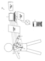
- FIG. 2 is a schematic diagram showing the configuration of the biometric system 100 in the embodiment of the present invention.
- the biometric system 100 of the present invention is configured to include at least one or more biosensors (2 to 6 and 8) and an analysis apparatus (biological measurement apparatus) 1.
- the biometric system 100 may include an information providing device 7 that provides various types of information related to the measurement of the subject.
- the biological sensor senses the state of the subject and supplies the detected biological signal information to the analysis device 1.
- the biosensor includes an acoustic sensor 2 (acoustic sensors 2 a and 2 b) that detects sound emitted by the subject, and a pulse oximeter that measures the subject's percutaneous arterial oxygen saturation (SpO 2 ). 3, a pulse wave sensor 4 that detects the pulse wave of the subject, a thermometer 5 that measures the body temperature of the subject, and an acceleration sensor 6 that detects the body movement (body motion) of the subject.
- an electrocardiograph 8 that detects the electrical activity of the subject's heart may be provided as a biosensor.
- Various sensors transmit biological signal information (sound, SpO 2 , pulse wave, body temperature, acceleration, electrocardiogram, etc.) detected by the own device to the analysis device 1.
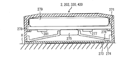
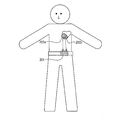
- the acoustic sensors 2a and 2b are close-contact microphones that are attached to the body of the subject and detect sound generated by the subject.
- An adhesive layer is provided on the surface of the acoustic sensor 2, and the acoustic sensor 2 is attached to the body surface of the subject by the adhesive layer.
- the mounting position of the acoustic sensor 2 may be a location where the target sound can be effectively picked up.
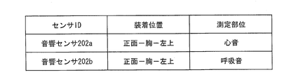
- the acoustic sensor 2a for detecting the subject's breathing sound, coughing sound, etc. is mounted near the airway, and the subject's heart sound and heartbeat
- the acoustic sensor 2b for detecting the number and the like is attached to the left chest (viewed from the subject).
- the acoustic sensor 2a transmits sound data of the detected breathing sound to the analysis device 1 as biological signal information.
- the acoustic sensor 2b transmits sound data of the detected heart sound to the analysis device 1 as biological signal information.
- the pulse oximeter 3 includes LEDs that emit red light and infrared light, respectively, and the arterial blood oxygen saturation is calculated based on the amount of transmitted light generated as a result of the light emitted from these LEDs passing through the fingertip of the subject. measure. Further, the pulse rate may be measured.
- the pulse oximeter 3 transmits measurement data in which the measured SpO 2 is associated with the measurement time to the analysis device 1 as biological signal information.
- the electrocardiograph 8 detects the electrical activity of the heart.
- the electrocardiograph 8 does not measure the state of the subject at rest (electrocardiogram) for a short time, but continuously measures the state of the subject during daily life. Used for purposes. Therefore, it is preferable to adopt a Holter electrocardiograph as the electrocardiograph 8.
- the Holter electrocardiograph can continuously measure the electrocardiogram during the daily life of the subject over a long period of time (24 hours a day or more).
- the electrocardiograph 8 is composed of an electrode attached to the body of the subject and a measuring instrument main body. The measuring instrument main body controls each electrode, analyzes the electrical signal obtained from each electrode, and creates an electrocardiogram.
- the measuring instrument main body has a function of communicating with the analysis apparatus 1 and transmits the created electrocardiogram data to the analysis apparatus 1 as biological signal information.
- the electrocardiograph 8 has a shape that is small, lightweight, and excellent in portability so as not to hinder the daily life of the subject.
- the analysis apparatus 1 can analyze the electrocardiogram supplied from the electrocardiograph 8 and extract parameters representing the heart activity state such as the heart rate and the QRS width.
- the analysis apparatus 1 measures the state of the subject based on the biological signal information acquired from the biological sensor.
- the analysis device 1 extracts one or a plurality of various information related to the subject from the acquired biological signal information. And a measurement result can be obtained by using these as a parameter and applying to a biometric process.
- the analysis apparatus 1 of the present invention can select parameters to be used for the above-described biometric processing depending on the purpose of measurement of what state the subject wants to measure, that is, the measurement item. For this reason, the accurate determination suitable for the purpose of the measurement can be realized.
- the analysis device 1 is directly input to the external device and external acquisition information acquired from a device other than the biosensor (such as the information providing device 7). Parameters can be extracted from manually input information and used.
- a parameter obtained from the biological signal information of the biological sensor is referred to as a “biological parameter”, and a parameter obtained from the externally acquired information or the manual input information is referred to as an “external parameter”. Is used when it is necessary to distinguish between
- the biological parameter reflects the physiological state of the subject.
- the biological parameter for example, “volume” and “frequency” acquired from sound data (biological signal information) detected by the acoustic sensor 2 are assumed. Further, when the waveform is patterned, by analyzing the waveform pattern, the “presence / absence”, “long / short”, “number of times”, etc. of the waveform may be extracted as biological parameters.
- electrocardiogram biological signal information
- biological signal information biological signal information
- External parameters reflect the environmental conditions outside the body of the subject, whereas the biological parameters reflect the physiological state of the subject.
- Specific examples of the external parameter include, for example, the specification information of the biosensor (version information, what kind of information can be detected, etc.), and the installation position information of the biosensor (chest, abdomen, back, airway) Nearby), subject (subject) information about the subject (subject's age, gender, sleep time, last meal time, exercise amount, past disease history, etc.) and the measurement environment (temperature, Atmospheric pressure, humidity, etc.), but is not limited thereto.
- the analysis apparatus 1 can achieve a more accurate determination suitable for the purpose of measurement by deriving the measurement result by appropriately combining the external parameter with the external parameter. Below, the structure of this analyzer 1 is demonstrated in detail.
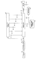
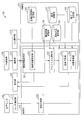
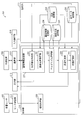
- FIG. 1 is a block diagram showing a main configuration of an analysis apparatus 1 according to an embodiment of the present invention.
- the analysis device 1 includes a control unit 10, a storage unit 11, a wireless communication unit 12, a communication unit 13, an input operation unit 14, and a display unit 15.
- the wireless communication unit 12 wirelessly communicates with various biological sensors in the biological measurement system 100.
- the wireless communication means it is assumed that short-range wireless communication means such as Bluetooth (registered trademark) communication or WiFi communication is adopted and direct short-range wireless communication is performed with various biological sensors.
- short-range wireless communication means such as Bluetooth (registered trademark) communication or WiFi communication
- WiFi communication wireless local area network
- a local area LAN may be constructed, and wireless communication with various biological sensors may be performed via the local area LAN.
- the analysis device 1 may not include the wireless communication unit 12 when performing wired communication with the biosensor, but it is preferable to realize communication between each biosensor and the analysis device 1 wirelessly. . This is because wireless communication makes it easy to attach the biosensor to the subject, reduces restrictions on the behavior of the subject in the measurement environment, and reduces the stress and burden on the subject.
- the communication unit 13 communicates with an external device (such as the information providing device 7) via a wide area communication network.
- the communication unit 13 transmits / receives information to / from the information providing device 7 via the Internet or the like.
- the analysis device 1 receives externally acquired information for extracting external parameters used for the biological measurement process from the information providing device 7 via the communication unit 13.
- external acquisition information acquired by the communication unit 13 weather, temperature, atmospheric pressure, humidity, specification information of each biosensor to be used, and the like are assumed.
- the analysis device 1 determines which biometric sensor should be used according to which measurement item, or compatibility when using a plurality of biosensors simultaneously. It is possible to grasp the good and bad and contraindications.
- the input operation unit 14 is used by a user (including a subject himself or an operator who performs measurement) to input an instruction signal to the analysis apparatus 1.
- the input operation unit 14 is a keyboard, a mouse, a touch panel, a touch sensor, a touch pen, or an appropriate input such as a voice input unit and a voice recognition unit configured by a plurality of buttons (cross key, determination key, character input key, etc.). Consists of devices.
- the user directly inputs information (manual input information) necessary for measuring the purpose (measurement item) of the measurement to be started from the input device 14 using the input operation unit 14. For example, parameters such as the subject's age, sex, average sleep time, sleep time on the measurement date, latest meal time, meal content, and amount of exercise are input to the analysis apparatus 1 via the input operation unit 14.
- the display unit 15 displays the measurement result of the biometric processing executed by the analysis device 1 or displays an operation screen for the user to operate the analysis device 1 as a GUI (Graphical User Interface) screen.
- GUI Graphic User Interface
- the user can display an input screen for inputting each of the parameters described above, or the user can display an operation screen for instructing the start of measurement by specifying a measurement item, Display a result display screen showing the measurement results.
- the display unit 15 is configured by a display device such as an LCD (Liquid Crystal Display).
- the control unit 10 performs overall control of each unit included in the analysis device 1 and includes, as functional blocks, an information acquisition unit 20, a parameter extraction unit 21, a parameter selection unit 22, an index calculation unit 23, a state determination unit 24, and A measurement item determination unit 25 is provided.
- Each of these functional blocks includes a CPU (central processing unit), a program stored in a storage device (storage unit 11) realized by a ROM (read only memory), etc., a RAM (random access memory) (not shown), and the like. This can be realized by reading out and executing.
- the storage unit 11 includes (1) a control program executed by the control unit 10, (2) an OS program, (3) an application program for the control unit 10 to execute various functions of the analysis device 1, and (4 ) Stores various data to be read when the application program is executed.
- the storage unit 11 stores various programs and data that are read when the biological measurement process executed by the analysis apparatus 1 is executed.
- the storage unit 11 includes a parameter storage unit 30, a measurement method storage unit 31, an index calculation rule storage unit 32, and an index storage unit 33.
- the analysis device 1 includes a temporary storage unit (not shown).
- the temporary storage unit is a so-called working memory that temporarily stores data used for calculation, calculation results, and the like in the course of various processes executed by the analysis apparatus 1, and includes a RAM or the like.
- the information acquisition unit 20 of the control unit 10 acquires various information necessary for the biological measurement process. Specifically, the information acquisition unit 20 acquires biological signal information from the biological sensor via the wireless communication unit 12. The information acquisition unit 20 acquires external acquisition information from the information providing device 7 via the communication unit 13. Further, the information acquisition unit 20 acquires manual input information input to the own device via the input operation unit 14. For example, the information acquisition unit 20 acquires sound data of the breathing sound of the subject from the acoustic sensor 2a as biological signal information.
- the information acquisition unit 20 communicates with each biosensor when the measurement item when the analysis apparatus 1 executes the biometric measurement process is determined, and a biosensor necessary for measurement of the measurement item is obtained. It may be confirmed whether or not communication is possible (active state).
- the parameter extraction unit 21 extracts parameters used for the biometric measurement process from various information acquired by the information acquisition unit 20.
- the parameter extraction unit 21 extracts biological parameters from the biological signal information acquired from the biological sensor, and extracts external parameters from externally acquired information acquired from the outside or manual input information input to the device itself.
- the parameter extraction unit 21 is configured to extract parameters designated by default from predetermined biological signal information. For example, “sound volume” and “frequency” are extracted from the sound data.
- the measurement method storage unit 31 is referred to, and the separate parameter is acquired according to the extraction method stored in the measurement method storage unit 31.
- the separate parameter is “a maximum value among the frequencies detected in ⁇ minutes” or the like, and is a parameter extracted through a more complicated analysis procedure.
- the parameter extraction unit 21 stores the extracted parameters in the parameter storage unit 30 in association with the acquired biological signal information or biological sensor.
- the measurement item determination unit 25 determines the purpose of measurement of the biological measurement process to be executed by the analysis apparatus 1, that is, the measurement item. There are several methods for determining the measurement item. As the simplest configuration, a configuration is possible in which measurement items that can be measured by the analysis apparatus 1 are presented to the user via the display unit 15 and are selected by the user via the input operation unit 14. The measurement item determination unit 25 transmits information on measurement items specified by the user to each unit of the analysis apparatus 1.
- the parameter selection unit 22 selects a parameter necessary for executing the biometric measurement process related to the measurement item according to the measurement item designated by the user.
- the parameter selection unit 22 refers to the parameter designation information stored in the measurement method storage unit 31 and selects a parameter that matches the designated measurement item.
- the operation of the parameter selection unit 22 will be described later in detail based on the data structure of the measurement method storage unit 31.
- the index calculation unit 23 uses the parameter selected by the parameter selection unit 22 to calculate an index corresponding to the designated measurement item.
- the index calculation unit 23 reads out the index calculation rule stored in the index calculation rule storage unit 32 corresponding to the specified measurement item, and determines the index of the specified measurement item according to the index calculation rule. calculate.
- the index calculation unit 23 follows the “apnea degree calculation rule” stored in the index calculation rule storage unit 32 and the index “apnea degree”. Is calculated.
- the data structure of the index calculation rule will be described later.
- the index calculation unit 23 stores the calculated index in the index storage unit 33.
- the index may be accumulated in association with the measurement date and time and the subject information (subject information).
- the state determination unit 24 determines the state of the subject based on the index calculated by the index calculation unit 23. Determination criterion information is stored in the index calculation rule storage unit 32, and the state determination unit 24 determines the state of the subject based on the calculated index according to the determination criterion information. For example, the state determination unit 24 determines the state of the subject related to the measurement item by a three-step evaluation of “normal”, “attention required”, and “abnormal”.
- the measurement results output by the index calculation unit 23 and the state determination unit 24, that is, the indexes and the state determination result of the subject are output to the display unit 15. Thereby, it becomes possible to present a measurement result to a user in an easy-to-understand manner.
- the parameter storage unit 30 stores the parameters extracted by the parameter extraction unit 21.
- the extracted parameters are managed for each parameter type so that the analysis apparatus 1 can identify them.
- the parameter types are “volume”, “frequency”, and the like, for example. Furthermore, when a plurality of subjects are measured using a plurality of biosensors, it is desirable that each parameter is managed for each subject ID and each biosensor ID.
- the measurement method storage unit 31 stores parameter designation information for designating the type of parameter used for the biological measurement process for each measurement item.
- the measurement method storage unit 31 stores the mounting position designation information for each measurement item and for each type of biosensor when the mounting position of the biosensor differs depending on the measurement item even for the same type of biosensor. You may remember it. Thereby, when each measurement item is designated, each unit of the analysis apparatus 1 has an error such as that the biometric sensor is not mounted at an appropriate position or cannot communicate with a biometric center mounted at an appropriate position. Can be detected and dealt with.
- the measurement method storage unit 31 may store an index that is finally calculated for each measurement item in association with each other.
- the index calculation unit 23 can recognize what index should be calculated when a measurement item is designated. For example, when the measurement item “apnea measurement” is designated, it is recognized that the corresponding index “apnea” is calculated.
- the index calculation rule storage unit 32 stores an index calculation rule for calculating an index for each measurement item.
- the index calculation rule indicates an algorithm for all processes until an index is calculated using a selected parameter. For example, when the measurement item “apnea measurement” is designated, the index calculation unit 23 reads the “apnea calculation rule” from the index calculation rule storage unit 32, and the index is calculated according to the algorithm indicated there. The “apnea level” can be calculated. Furthermore, in the index calculation rule storage unit 32, determination criterion information for determining the state of the subject based on the calculated index is stored in association with each measurement item.
- the state determination unit 24 refers to the determination standard information of the apnea degree, and according to the determination standard, the state of the subject regarding the measurement item “apnea measurement” Determine.
- the index storage unit 33 stores the index calculated by the index calculation unit 23.
- the calculation of the index is preferably performed periodically, and the calculated index is preferably stored in association with the measurement date and subject information. This makes it possible to observe changes over time for the same index of the same subject, and more accurately determine the state of the subject (particularly normal or abnormal).
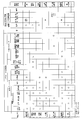
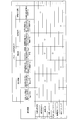
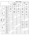
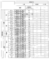
- FIG. 3A and 3B are diagrams showing the data structure of information stored in the measurement method storage unit 31.
- FIG. 3A illustrates a correspondence relationship between measurement items for parameter designation information regarding general-purpose parameters, mounting position designation information, and corresponding indexes, using a specific example.
- FIG. 3B shows the correspondence between the parameter designation information related to the special parameter and the measurement item using a specific example.
- an essential parameter (hereinafter, an essential parameter) is associated with an auxiliary parameter (auxiliary parameter) for the purpose of improving accuracy.
- an essential parameter hereinafter, an essential parameter
- auxiliary parameter auxiliary parameter
- each part (especially parameter selection part 22) of the control part 10 which performs a biological measurement process will start based on the determined measurement item, if a measurement item is determined by the measurement item determination part 25. Parameters necessary for the biological measurement process can be grasped.
- each unit when performing the biometric measurement process of the measurement item “1: apnea measurement”, each unit must have parameters for waveform presence / absence, volume, waveform length short / number of waveforms, and optionally SpO 2 and heart rate. It can be recognized that the following parameters are used.
- the biosensor particularly the acoustic sensor 2
- the optimal mounting is required in order to perform accurate measurement suitable for the measurement item. It is desirable that the position is fixed. Therefore, as shown in FIG. 3A, mounting position designation information is stored in association with each measurement item.
- essential parameters are obtained for the respiratory sound that can be collected from the vicinity of the airway by making it necessary to attach an acoustic sensor to the airway. That is, each unit of the control unit 10 can recognize it.
- the information acquisition unit 20 provides information on whether necessary information should be acquired from the biological sensor. It can be grasped from the device 7 or user input.
- biosensors to be used are determined in advance (FIG. 2), and the correspondence between these biosensors and parameters that can be extracted is grasped in advance as follows. .
- the parameters of waveform presence / absence, volume, frequency, waveform length, and number of waveforms can be extracted from the biological signal information of the acoustic sensor 2a (the mounting position is arbitrary and specified by the mounting position specifying information).
- the heart rate parameter may be extracted together.
- the heart rate parameter can be extracted from the biological signal information of the acoustic sensor 2b (the wearing position is fixed at the left chest).
- the SpO 2 parameter can be extracted from the biological signal information of the pulse oximeter 3 (the mounting position is fixed with a fingertip). Further, a pulse rate parameter may be extracted.
- Parameters of pulse wave propagation speed and pulse rate can be extracted from the biological signal information of the pulse wave sensor 4 (the mounting position is arbitrary and specified by the mounting position specifying information).
- the parameters of body temperature and body temperature change can be extracted from the biological signal information of the thermometer 5 (the wearing position is arbitrary and is designated by the wearing position designation information).
- the body motion parameters can be extracted from the biological signal information of the acceleration sensor 6 (the mounting position is arbitrary and specified by the mounting position specifying information).
- the optimal mounting position may be determined in advance by the mounting position designation information. That is, the mounting position designation information is not limited to the example illustrated in FIG. 3A.
- the information acquisition unit 20 of the analysis apparatus 1 grasps parameters necessary for the measurement and recognizes from which biological sensor the biological information signal should be acquired. be able to.
- the correct mounting position of the biosensor can be recognized and presented to the user.
- the configuration of the analysis apparatus 1 of the present invention is not limited to the above.
- the correspondence between the biological center and the parameter such as from which biometric sensor the parameter is acquired, which parameter is used for which measurement item without defining the above correspondence
- Only the correspondence between the measurement item and the parameter may be determined in the measurement method storage unit 31. Thereby, the structure of the analyzer 1 can be simplified and the processing load of the analyzer 1 can be reduced.
- an index type that can be calculated with respect to the measurement item may be associated and stored.
- the index calculation unit 23 can recognize which index should be calculated when the measurement item is determined.
- special parameters that define the extraction method in detail may be stored in association with each measurement item.
- the parameter “Waveform presence / absence” is used for the biological measurement process.
- a special parameter “presence / absence of waveform at a specific frequency of 100 to 200 Hz” is used as the measurement item “3: asthma measurement”. Correlate.
- the parameter selection unit 22 can determine that a special parameter “whether or not a waveform with a specific frequency of 100 to 200 Hz” is necessary when measuring the measurement item “3: asthma measurement”. Is not stored in the measurement method storage unit 31, the parameter extraction unit 21 can be requested to extract “whether or not the waveform has a specific frequency of 100 to 200 Hz”.
- the parameter extraction unit 21 may be configured to extract all parameters assumed in FIG. 3A and FIG. Or it is good also as a structure which extracts both a general-purpose parameter and a special parameter according to the request
- FIG. 4 is a diagram for explaining a data flow between main members in the analysis apparatus 1 from when the analysis apparatus 1 receives an instruction to start the biometric measurement process until the measurement result of the process is output.
- the measurement item determination unit 25 receives an instruction to start the biological measurement process via the input operation unit 14 and also receives information on the measurement item selected by the user, and determines the measurement item as “1: Apnea measurement”. To do.
- the measurement item determination unit 25 transmits the determined measurement item d1 to the parameter selection unit 22, the index calculation unit 23, and the state determination unit 24.
- the parameter selection unit 22 refers to the measurement method storage unit 31 (FIGS. 3A and 3B), identifies the necessary parameters based on the transmitted measurement item d1, and identifies the identified parameters, that is, the waveform (respiration) d2, (breathing) volume d3, waveform (breathing) length d4, waveform (breathing) number d5, SpO 2 d6, and heart rate d7 are acquired from the parameter storage unit 30 and supplied to the index calculation unit 23.
- the waveform presence / absence d2 indicates “the number of times that respiration stops for 10 seconds or more” as shown in FIG. 3B.
- SpO 2 d6 and heart rate d7 are arbitrary auxiliary parameters, and therefore may not be supplied to the index calculation unit 23 unless stored in the parameter storage unit 30.
- the index calculation unit 23 reads the index calculation rule from the index calculation rule storage unit 32 based on the transmitted measurement item d1.
- the apnea degree calculation rule d8 is read.
- the apnea degree calculation rule d8 indicates an algorithm for calculating the apnea degree using the parameters d2 to d7 described above.
- the index calculation unit 23 calculates the apnea degree d9 using the parameters d2 to d7 according to the apnea degree calculation rule d8.
- the state determination unit 24 reads the calculated criterion determination criterion information from the index calculation rule storage unit 32.
- the criterion information d10 of the calculated apnea degree d9 is read out.
- the criterion information d10 is information indicating a criterion for determining a state related to apnea of the subject based on the apnea degree d9.
- the state determination unit 24 determines whether the state or symptom related to the apnea of the subject is normal, needs attention, or is abnormal based on the apnea degree d9 according to the determination reference information d10, and the state determination result d11 is obtained. Output.
- the measurement result including the apnea degree d9 and the state determination result d11 is output to the display unit 15 and displayed. Thereby, the user can confirm the measurement result concerning the designated measurement item on the display unit 15.
- the analysis apparatus 1 may include a light emitting unit and notify the state determination result d11 by emitting light that is color-coded according to the state determination result, such as green, yellow, and red. Or it is good also as a structure which uses a light emission part selectively according to a state determination result, such as lighting, light extinction, and blinking. Alternatively, the state determination result d11 may be notified by providing a sound output unit and using sound or sound effects depending on the state determination result.
- the data structure of the index calculation rule storage unit 32 that stores the apnea calculation rule d8 and the determination reference information d10 will be described in more detail with a specific example.
- FIGS. 5 to 11 are diagrams showing the data structure of the index calculation rule and the determination criterion information stored in the index calculation rule storage unit 32.
- FIG. Each of FIGS. 5 to 11 shows specific examples of index calculation rules and determination criterion information corresponding to the seven measurement items shown in FIGS. 3A and 3B.
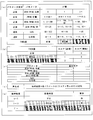
- FIGS. 5A to 5D are diagrams showing specific examples of apnea calculation rules
- FIG. 5E is a diagram showing a specific example of apnea determination criterion information.
- Sleep apnea syndrome is a symptom of falling into apnea or hypopnea frequently during sleep.
- the airflow in the mouth and nose is stopped for 10 seconds or more, and as a guideline for judging a hypopnea state, the ventilation volume is reduced by 50% or more for 10 seconds or more. Conceivable.
- the determination of apnea is as follows: presence or absence of breathing (number of times breathing stops for 10 seconds or more), volume of breathing sound, length of breathing (time length of expiration and inspiration), per unit time
- the respiratory rate and SpO 2 parameters were used.
- the “apnea level” in the present embodiment indicates that the higher the value, the higher the possibility of sleep apnea syndrome.
- the example of the parameter used for determination of apnea degree is an example, and is not limited to the example mentioned above.
- a pulse rate parameter may be used.
- the apnea degree calculation rule evaluates each parameter obtained from the parameter selection unit 22 as a normal value, a caution value, or an abnormal value in three stages. Corresponding relationships are included. In the example shown in FIG. 5A, this correspondence relationship is expressed in a table format, but this is an example and there is no intention to limit the present invention.
- IF values For each parameter, three types of threshold values (IF values) are stored in association with each other, and each of the three types of IF values is associated with a three-stage evaluation result (THEN value) of normal, caution, and abnormality. ing. That is, the THEN value of the parameter is determined depending on which of the three IF values satisfies the parameter value.
- THEN value three-stage evaluation result
- the threshold value stored as the IF value in the table is not limited to the example shown in the figure, and an appropriate value may be determined based on medical grounds and experience.
- the apnea calculation rule includes score information for assigning a score corresponding to the evaluation to the parameters evaluated in three stages.
- the score information is expressed in a table format, but this is an example and there is no intention to limit the present invention.
- the index calculation unit 23 sets 0 for a parameter evaluated as “normal”, 1 for a parameter evaluated as “attention required”, and “abnormal”.
- a score of 2 is assigned to the evaluated parameter.
- scores of 0, 0, and 1 are assigned to the parameters of “normal”, “attention required”, and “abnormal”, respectively.
- the waveform (respiration) presence / absence d2 parameter is evaluated as “normal”, the waveform (respiration) presence / absence d2 parameter is essential, and therefore a score “0” is assigned.
- the apnea calculation rule may include weighting information to be given to the score obtained for each parameter.
- the weighting information is expressed in a table format, but this is an example and there is no intention to limit the present invention.
- the weight is stored in association with each parameter. A large weighting value indicates that the parameter is information that is more important and important in calculating the index.
- the waveform (breathing) presence / absence d2 indicating “the number of times breathing stops for 10 seconds or more” is the most important information to be considered in calculating the apnea degree. Therefore, the weight is set to “4”.
- a parameter that is not very important, the number of waveforms (breathing), SpO 2 , and heart rate may not be weighted, that is, the weight may be set to “1”.
- the apnea degree calculation rule includes a calculation formula for calculating the index “apnea degree” based on the score of each parameter.
- the calculation formula of (d) of FIG. 5 is an example, and is not intended to limit the present invention.
- the index calculation unit 23 calculates the apnea degree by summing the final scores of the parameters d2 to d7.
- the index calculation rule storage unit 32 stores determination criterion information for determining the state of the subject regarding the index “apnea level”.
- the determination criterion information is expressed in a table format, but this is an example and is not intended to limit the present invention.
- the state determination result to be determined is associated with the calculated apnea value.
- the state determination unit 24 determines the state related to the apnea of the subject according to the determination criterion information illustrated in FIG. For example, when the apnea degree is calculated as “3”, the state determination unit 24 determines that the state related to the apnea of the subject is “normal”.
- information defining a method for displaying the state determination result may be associated with the determination criterion information table.
- the display “green” is associated with the state determination result “normal”. This means that the state determination result is displayed in green letters or notified with a green lamp.
- the state determination result is color-coded and output, so that the user can more intuitively understand the state determination result.
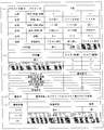
- FIGS. 6A to 6D are diagrams showing a specific example of the sleep depth calculation rule
- FIG. 6E is a diagram showing a specific example of the sleep depth determination criterion information.
- the “sleep depth” in the present embodiment indicates that the higher the value, the deeper the sleep.
- the sleep depth calculation procedure and the state determination procedure based on the various types of information in FIGS. 6A to 6E are parameters used in comparison with the procedure based on FIGS. 6A to 6E. This is the same except that the threshold is different. Therefore, description is not repeated here. However, in the determination of the sleep depth, not the presence / absence of abnormality, but the determination of the sleep depth and depth is performed.
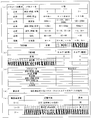
- FIGS. 7A to 7D are diagrams showing specific examples of asthma severity calculation rules
- FIG. 7E is a diagram showing a specific example of determination criteria information for asthma severity.
- “Asthma severity” in the present embodiment indicates that the higher the value, the more severe the symptoms of asthma.
- the procedure for calculating the severity of asthma and the procedure for determining the state based on various types of information in FIGS. 7A to 7E are used in comparison with the procedure based on FIGS. 5A to 5E. The same except that the parameters and thresholds are different. Therefore, description is not repeated here.
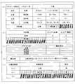
- FIGS. 8A to 8D are diagrams illustrating specific examples of rules for calculating the heart activity level
- FIG. 8E is a diagram illustrating a specific example of criteria information for determining the heart activity level.
- the “heart activity” in the present embodiment indicates that the higher the value, the more unstable and abnormal the heart activity.
- the cardiac activity calculation procedure and the state determination procedure based on the various types of information in (a) to (e) of FIG. 8 are used in comparison with the procedure based on (a) to (e) of FIG. The same except that the parameters and thresholds are different. Therefore, description is not repeated here.
- FIGS. 9A to 9E are diagrams showing specific examples of rules for calculating digestive organ activity
- (e) is a diagram showing specific examples of criteria information for digestive activity.
- “Digestive activity” in the present embodiment indicates that the higher the value, the more unstable and abnormal the digestive activity.
- the digestive activity level calculation procedure and state determination procedure based on the various types of information in FIGS. 9A to 9E are used in comparison with the procedure based on FIGS. 5A to 5E. This is the same except that the parameters and thresholds to be used are different. Therefore, description is not repeated here.
- FIGS. 10A to 10D are diagrams showing specific examples of the cardiovascular activity calculation rule
- FIG. 10E is a diagram showing a specific example of the criteria information for determining cardiovascular activity.
- “Cardiovascular activity” in the present embodiment indicates that the higher the value, the more unstable and abnormal the activity of the cardiovascular activity.
- the procedure for calculating the degree of circulatory activity and the procedure for determining the state based on the various types of information in FIGS. 10 (a) to (e) are used in comparison with the procedure based on (a) to (e) in FIG. This is the same except that the parameters and thresholds to be used are different. Therefore, the overlapping description will not be repeated here.
- the age of the subject may be used as an auxiliary external parameter in calculating the cardiovascular activity. Since the health condition of the circulatory organ (particularly blood vessels) greatly depends on the age, the state determination suitable for the age of the subject can be performed by considering the age of the subject.
- the IF value (threshold value) of the essential parameter “pulse wave (propagation velocity)” shown in FIG. More specifically, for example, a normal IF value “less than 1200 cm / s”, a cautionary IF value “more than 1200 cm / s and less than 1400 cm / s”, and an abnormal IF value shown in FIG.
- the circulatory activity can be calculated with higher accuracy by changing the weighting value of the parameter of the pulse wave (propagation speed) according to the age of the subject. it can.
- another index “degree of arteriosclerosis” may be calculated using the same parameters as those for calculating the degree of cardiovascular activity.
- the index calculation rule storage unit 32 may separately store an arteriosclerosis calculation formula as an arteriosclerosis calculation rule.
- FIGS. 11A to 11D are diagrams showing specific examples of cough severity calculation rules
- FIG. 11E is a diagram showing specific examples of criteria information for determining cough severity.
- the “cough severity” in the present embodiment indicates that the higher the value, the more severe the cough symptoms and the higher the probability of being abnormal.
- the cough severity calculation procedure and state determination procedure based on the various types of information shown in FIGS. 11A to 11E are used in comparison with the procedure based on FIGS. 5A to 5E. The same except that the parameters and thresholds are different. Therefore, the overlapping description will not be repeated here.
- the disease history of the subject may be used as an auxiliary external parameter in calculating the cough severity.
- Patients with respiratory disease often develop a characteristic cough (specific frequency cough), and the effects of coughing from the original respiratory disease must be subtracted here. Therefore, for example, as shown in FIG. 11 (c), the cough severity can be calculated more accurately by changing the weighting value of the frequency parameter according to whether or not the subject is a respiratory disease patient. Can do.
- the index calculation unit 23 processes the parameter selected according to the measurement item according to the index calculation rule according to the measurement item, and calculates the index. Therefore, the index calculation unit 23 is more accurate and suitable for the measurement item. A biometric process can be performed.
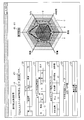
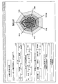
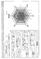
- [Measurement result display example] 12 to 18 are diagrams illustrating examples of display screens when the measurement result obtained by the analysis apparatus 1 executing the biological measurement process is displayed on the display unit 15.
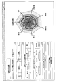
- FIG. 12 shows an example in which the analysis apparatus 1 displays the measurement result obtained when the biometric measurement process is executed for the measurement item “1: apnea measurement”.
- the index calculated by the index calculation unit 23 (here, “apnea degree d9”) and the state determination result d11 determined by the state determination unit 24 are displayed as measurement results.
- the apnea degree d9 and the state determination result d11 are preferably displayed in a format that is easy for the user to understand, and may be displayed in text or may be displayed in various forms of graphs.
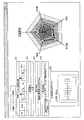
- the measurement result can be displayed in a text and radar chart format.
- the calculated index is set to the center upper axis
- the parameter used for calculating the index is set to the other direction axis
- the center is 0, and the maximum value that can take the outside of the axis is set.
- the calculated index indicates that the smaller the value, that is, the closer to the center of the chart, the “normal”, so the area A closest to the center is “normal” and the middle area B is “noticeable”. ”And the outer region C is“ abnormal ”.
- the intermediate value is “normal” and the value becomes “careful” or “abnormal” if the value is too small or too large.
- the region A closest to the center and the outer region C represent “abnormal”
- the middle region B represents “normal”.
- the vicinity of the boundary between the area A and the area B and the vicinity of the boundary between the area A and the area C mean “attention required”.
- the boundary position of each region changes depending on the index criterion information and the IF value of each parameter, so the length from the center to the boundary position may vary from axis to axis. Further, the axes for plotting the index and each parameter do not have to be all on the same plane. If the display area is wide, a plurality of radar charts may be created and displayed.
- the national average value, ideal value, previous measurement value of the same subject, etc. may be plotted and displayed as a broken line D so that it can be compared with the current measurement result (solid line).
- the information acquisition unit 20, the parameter selection unit 22, and the index calculation unit 23 may output various types of information obtained when referring to the measurement method storage unit 31 to the display unit 15.
- the information acquisition unit 20 includes information 120 indicating the type of the biosensor used (communication) used in the measurement of the measurement item “apnea measurement”, and mounting position designation information on the biosensor.
- information 121 indicating the mounting position of the sensor is displayed.
- the parameter selection unit 22 displays parameter information 122 selected as an essential parameter and parameter information 123 selected as an auxiliary parameter for the measurement item “apnea measurement”.
- the index calculation unit 23 displays index information 124 corresponding to the measurement item “apnea measurement”.
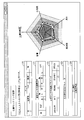
- FIG. 13 shows an example in which the analysis apparatus 1 displays the measurement result obtained when the biometric processing is executed for the measurement item “2: sleep state measurement”.
- FIG. 14 shows an example in which the analysis apparatus 1 displays the measurement result obtained when the biometric measurement process is executed for the measurement item “3: Asthma measurement”.
- FIG. 15 shows an example in which the analysis apparatus 1 displays the measurement result obtained when the biometric processing is executed for the measurement item “4: heart monitoring”.
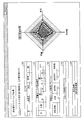
- FIG. 16 shows an example in which the analysis apparatus 1 displays the measurement result obtained when the biometric measurement process is executed for the measurement item “5: digestive organ monitoring”.
- FIG. 17 shows an example in which the analysis apparatus 1 displays the measurement result obtained when the biometric measurement process is executed for the measurement item “6: cardiovascular monitoring”.
- the index calculation unit 23 of the analysis apparatus 1 can calculate the index “degree of arteriosclerosis” using the same parameter as the measurement item “6: cardiovascular monitoring”.
- the display may be switched to a radar chart related to the index “degree of arteriosclerosis” in accordance with a user operation.
- FIG. 18 shows an example in which the analysis apparatus 1 displays the measurement result obtained when the biometric processing is executed for the measurement item “7: cough monitoring”.
- the user can confirm the information displayed on the display unit 15 and easily grasp the measurement result related to the selected measurement item.
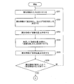
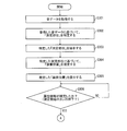
- FIG. 19 is a flowchart showing the flow of the biometric measurement process executed by the analysis apparatus 1.
- the measurement item determination unit 25 When an instruction to start measurement of the subject is input to the analysis apparatus 1 via the input operation unit 14 (YES in S1), the measurement item determination unit 25 then sets the “measurement item”. An input is accepted (S2). For example, when the user selects the measurement item “apnea measurement”, the measurement item determination unit 25 determines “1: apnea measurement” as the measurement item of the biological measurement process to be started.
- the information acquisition unit 20 refers to the measurement method storage unit 31 and confirms whether or not all the biosensors necessary for measuring the determined measurement item are active (S3).
- the information acquisition unit 20 determines whether at least the acoustic sensor 2a is active among the acoustic sensor 2a mounted near the airway, the acoustic sensor 2b mounted on the left chest, and the pulse oximeter 3. Check.
- the information acquisition unit 20 When the essential biosensor is inactive (NO in S3), the information acquisition unit 20 notifies the user that the biosensor is inactive and cannot be measured via the display unit 15. It is preferable to do this (S4). At this time, it is more preferable to notify the user of the type of necessary biosensor and the correct mounting position (near the airway and left chest) in a form that is easy to understand for the user (for example, in the drawing).
- the information acquisition unit 20 acquires biosignal information from each of these biosensors (S5).
- the information acquisition unit 20 acquires at least sound data near the airway from the acoustic sensor 2a, optionally, sound data of heart sounds from the acoustic sensor 2b, and measurement data of SpO 2 from the pulse oximeter 3. To do.
- the information acquisition unit 20 receives external acquisition information (such as the measurement day's climate, temperature, humidity, and atmospheric pressure) from the information providing device 7 and manual input information (subject ID or subject name, subject's subject) via the input operation unit 14. Age, sex, etc.) may be acquired as necessary (S6).
- external acquisition information such as the measurement day's climate, temperature, humidity, and atmospheric pressure
- manual input information subject ID or subject name, subject's subject
- Age, sex, etc. may be acquired as necessary (S6).
- the parameter extraction unit 21 extracts biological parameters from the acquired biological signal information (S7).
- the parameter extraction unit 21 may extract only the parameters used in the selected measurement item “1: apnea measurement” with reference to the measurement method storage unit 31 or the parameters listed in FIG. 3A. Of these, all parameters that can be extracted may be extracted. Further, when the external acquisition information and the manual input information are acquired, the parameter extraction unit 21 extracts external parameters from them (S8).
- the parameter extraction unit 21 stores the extracted parameters in the parameter storage unit 30.
- the parameter selection unit 22 refers to the measurement method storage unit 31 (FIGS. 3A and 3B) and selects a parameter to be used for the determined measurement item from the parameters stored in the parameter storage unit 30 ( S9).
- the parameter selection unit 22 associates the measurement item “1: apnea measurement” with or without the (airway) waveform, volume, waveform length, waveform number, SpO 2 and heart rate parameters. Select.
- parameter selection unit 22 When parameter selection unit 22 has obtained all necessary parameters from parameter storage unit 30 (YES in S10), it supplies it to index calculation unit 23 (S11).
- the index calculation unit 23 reads an index calculation rule corresponding to the selected measurement item from the index calculation rule storage unit 32 (S12), and calculates an index of the measurement item according to the index calculation rule (S13). .
- the “apnea level calculation rule” (for example, (a) to (d) of FIG. 5) corresponding to the measurement item “1: apnea level measurement” is read and supplied from the parameter selection unit 22.
- the apnea is calculated using the parameters.
- the calculated apnea degree is stored in the index storage unit 33 together with the measurement date, the subject ID, and the like.
- the state determination unit 24 determines the state of the subject based on the calculated index (S14).
- the state determination unit 24 performs determination according to the determination criterion information corresponding to the selected measurement item.
- the state determination unit 24 determines whether the apnea of the subject is normal. Determine if it needs attention or is abnormal.
- the index calculation unit 23 outputs the calculated index
- the state determination unit 24 outputs the result of the determination made to the display unit 15.
- the display unit 15 displays the measurement result and presents it to the user (S15).
- the measurement result is an execution result of a series of steps of the biometric processing shown in FIG. 19 executed by the analysis apparatus 1, and includes at least the calculated index and the determination result of the state. Furthermore, attached information such as information on the parameters used and what kind of index is calculated may be included in the measurement result. Display examples of the measurement results are as shown in FIGS.
- the parameter extraction unit 22 is based on the parameter designation information stored in the measurement method storage unit 31. 21 is preferably instructed to extract necessary parameters (S16). For example, according to the parameter designation information shown in FIG. 3B, the “apnea measurement” requires a parameter of “the number of times breathing stops for 10 seconds or more” with respect to the presence or absence of the waveform.
- the parameter selection unit 22 makes a request to the parameter extraction unit 21.
- the parameter extraction unit 21 extracts parameters according to the instructions, stores them in the parameter storage unit 30, and returns a response to the parameter selection unit 22.
- the analyzer 1 can be configured to extract, by default, highly versatile parameters for various measurement items, while extracting special parameters for specific measurement items as necessary. Thereby, it is possible to reduce the processing load of the biological measurement process and improve the processing efficiency.
- the analysis device 1 is configured to calculate one index by one biometric process and determine the state of the subject based on the calculated one index.
- the configuration of the analysis apparatus 1 of the present invention is not limited to this.
- the analysis apparatus 1 may measure a plurality of times for one measurement item by changing the date and time (that is, repeatedly obtain a biological parameter), and calculate the index a plurality of times. And the analysis apparatus 1 may determine a test subject's state by calculating
- the analysis apparatus 1 of the present invention stores, in the measurement method storage unit 31, in association with each measurement item, repeated measurement instruction information that specifies the timing for repeatedly calculating the corresponding index. ing.
- each unit of the control unit 10 illustrated in FIG. 1 refers to the measurement method storage unit 31 and the measurement item determined by the measurement item determination unit 25 Is read, and the timing of measurement is recognized.
- a time interval for periodically measuring such as “calculating an index for one month at a pace of once a day”, or a period for periodically measuring is specified.
- zone which performs a measurement may be defined in detail.
- each part of the control part 10 performs the biometric process mentioned above regularly according to repeated measurement instruction information.
- the index calculation unit 23 stores the index calculated at a pace of once every 24 hours in the index storage unit 33 in association with the subject ID and the measurement date for 31 days.
- the state determination unit 24 determines the state of the subject related to the instructed measurement item based on the accumulated index. In the example described above, indices for one month are accumulated, and the state determination unit 24 determines the state of the subject using these values.
- the index processing method and the criterion information at this time may be stored in the index calculation rule storage unit 32 for each measurement item.
- the processing performed by the state determination unit 24 includes, for example, plotting the index value on a two-dimensional graph with the index value on the vertical axis and the time on the horizontal axis to analyze the transition of the index, It is conceivable to calculate statistical values such as average value, maximum value, minimum value, and variance. For example, the state determination unit 24 compares the analysis result thus obtained with a standard value to determine the state of the subject related to the measurement item (for example, determination of normality, caution, or abnormality). Do.
- the state determination unit 24 compares the index accumulated in the past according to the repeated measurement instruction information with the index obtained by the biometric process performed once thereafter, and the biometric process is performed. You may determine the newest state of a test subject at the time of being implemented. Thus, by comparing with past values, it is possible to accurately determine the current state of the subject.
- an analysis method is stored for each measurement item, such as which index in the past is used as a comparison and how it is compared with the latest index. Just do it.
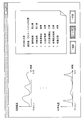
- FIG. 20 is a diagram illustrating an example in which a long-term tendency of a subject's condition is displayed as a measurement result.
- the two-dimensional graph created by the state determination unit 24 may be displayed on the display unit 15 for each measurement item. Thereby, the user can grasp
- the two-dimensional graph shown in FIG. 20 is an example, and the present invention is not limited to this.
- the range of the horizontal axis (time) to be displayed may be changed as necessary. For example, by changing the measurement period from “1 month” to “1 year”, it is possible to display the overall state determination result of the subject for one year based on the index of the subject accumulated for one year.
- the measurement period option button is displayed and selected by the user, the user can switch the measurement period with a simple operation.
- the measurement item determination unit 25 of the analysis apparatus 1 is configured to determine the measurement item designated by the user via the input operation unit 14 as the measurement item that is the purpose of the biometric processing to be performed from now. It was.
- the configuration of the analysis apparatus 1 of the present invention is not limited to this.
- the analysis apparatus 1 is configured so that the measurement item determination unit 25 specifies the measurement item or allows the user to select and narrow down to some candidates depending on which active biosensor is. be able to.
- the measurement item determination unit 25 confirms active biosensors via the information acquisition unit 20, and specifies measurement items that can be measured using biosignal information from these biosensors.
- the measurement item determination unit 25 determines the measurement item as a measurement item of a biometric process to be executed from now.
- the measurement item determination unit 25 displays only those measurement items as options on the display unit 15 and allows the user to select them.
- Embodiment 1-2 Another embodiment of the present invention will be described below with reference to FIGS.
- members having the same functions as those in the drawings described in the above-described embodiments are denoted by the same reference numerals, and description of contents overlapping those in the above-described embodiments is omitted.
- the biometric apparatus (analysis apparatus 1) of the present invention is an index corresponding to a target measurement item based on the parameter information 122 and the parameter information 123 as shown in FIGS. It was only informing the user whether or not the parameter for calculating the parameter was adopted.
- the magnitude of the influence of each parameter on the calculation of the index varies within the analysis apparatus 1 for each parameter.
- the analysis apparatus 1 expresses the magnitude of the influence of each parameter used at the time of calculation for each index as “priority” and manages it as “parameter attribute”, and manages each parameter.
- the “parameter attribute” is notified together with the measurement result.
- FIG. 21 is a block diagram illustrating a main configuration of the analysis apparatus 1 according to the present embodiment.
- the analysis device 1 differs from the analysis device 1 shown in FIG. 1 in the following points.
- the storage unit 11 further includes a parameter attribute storage unit 34 for storing the parameter attribute of each parameter.
- the control unit 10 of the analysis apparatus 1 is different in that it further includes a parameter attribute management unit 26 as a functional block.
- the parameter attribute management unit 26 manages parameter attributes stored in the parameter attribute storage unit 34.
- analysis device 1 may wirelessly communicate with the electrocardiograph 8 and acquire the subject's electrocardiogram from the electrocardiograph 8.
- FIG. 22 is a diagram illustrating a data structure of information stored in the parameter attribute storage unit 34.
- the parameter attribute management unit 26 of the analysis apparatus 1 manages the magnitude of the influence on the calculation of the index as “parameter attribute”, and stores the parameter attribute of each parameter for each index in the parameter attribute storage unit 34. Keep it.
- the parameter attribute is composed of several elements.
- the parameter attribute includes elements such as “priority”, “classification”, and “weighting”. Further, the parameter attribute may include an element such as “reliability”.
- the data structure shown in FIG. 22 is an example, and there is no intention to limit the data structure of the parameter attribute of the present invention. That is, the magnitude of influence (parameter attribute) on the calculation of the index may be expressed by other elements other than those described above.
- Element “category” is information indicating which category each parameter belongs to when it is classified into “essential parameter” and “auxiliary parameter”. For example, in the example shown in FIG. 22, in the measurement item “1: apnea measurement”, when the index “apnea level” is calculated, the classification of the parameter “presence / absence of waveform” is “essential”. This indicates that the parameter “presence / absence of waveform” is an indispensable parameter for calculating the index “apnea level”.
- the parameter attribute management unit 26 recognizes that the parameter whose element “classification” is “essential” has a large influence on the calculation of the index, and the parameter whose “assistance” has a small influence on the calculation of the index.
- the element “weighting” is a value constituting the index calculation rule as shown in (c) of FIGS. Specifically, it is a multiplier of the score obtained for each parameter in the index calculation formula. That is, the parameter attribute management unit 26 recognizes that the larger the “weighting” value of a parameter, the greater the effect that parameter has on the calculation of the index.
- the element “reliability” is information indicating the certainty of the parameter value. The greater the value of “reliability”, the higher the degree of accuracy of the parameter value. Therefore, it is considered that the accuracy of index calculation should be increased by increasing the influence of parameters with high “reliability” on index calculation.
- the value of “reliability” is determined in advance and fixed. Note that the value of “reliability” may be determined by, for example, the accuracy of the biological sensor. For example, for the parameters “whether waveform”, “volume”, etc. obtained from the acoustic sensor 2 that is easily affected by noise depending on the wearing environment, living environment, etc., the pulse oxy For the parameter “SpO 2 ” obtained from the meter 3, it can be considered to highly estimate “reliability”. Alternatively, since the parameter “heart rate” is obtained based on biological signal information obtained from two biological sensors of the acoustic sensor 2 and the electrocardiograph 8, the parameter “heart rate” is a more reliable value. "Can be highly estimated.
- the element “priority” is a value that directly represents the magnitude of the influence on the calculation of the parameter index. Naturally, it is understood that a parameter having a higher “priority” has a larger influence on the calculation of the index.
- the parameter attribute management unit 26 also recognizes in this way. As described above, the user can intuitively understand the importance of each parameter by expressing the magnitude of the influence on the calculation of the parameter index directly as the element “priority” and presenting it to the user. It becomes possible.
- the parameter attribute management unit 26 expresses the element “priority” in three stages of “high”, “medium”, and “low”. “Priority: High” indicates the parameter that has the greatest influence (important) on the calculation of the index among all parameters used for calculation of the index, and “Priority: Low” indicates the parameter The parameter that has the least influence (not important) on the calculation is shown.
- the parameter attribute management unit 26 may determine the element “priority” by comprehensive evaluation based on other elements. Based on FIG. 22, the index “apnea level” will be specifically described. Of the parameters used for calculating the index “apnea”, the parameter “classification” is “essential” and the parameter with the highest value of the element “weighting” is considered to be the most important parameter. In the index “apnea level”, the parameter “presence / absence of waveform” corresponds to this. Therefore, the parameter attribute management unit 26 sets “priority: high” for the parameter “presence / absence of waveform” of the index “apnea level”.
- the parameter attribute management unit 26 sets “priority: low” for the parameters “SpO 2 ” and “heart rate” of the index “apnea level”. Then, “priority: medium” is set in the other parameters of the index “apnea level”.
- the parameter attribute management unit 26 further considers one parameter as “priority” in consideration of the element “reliability”. It may be set to "degree;high” or "priority;low”. For example, the parameter attribute management unit 26 may set only the parameter “SpO 2 ” having lower reliability to “priority: low” in the index “apnea level”.
- the parameter attribute management unit 26 may assign the priority “first”, “second”,... As “priority” in order from the important parameter.
- the parameter attributes stored in the parameter attribute storage unit 34 are managed by the parameter attribute management unit 26, and are always parameter specification information stored in the measurement method storage unit 31 (FIGS. 3A and 3B). ) And the index calculation rule (FIGS. 5 to 11) stored in the index calculation rule storage unit 32 is maintained. That is, when the element “classification” or the element “weighting” of each parameter stored in the parameter attribute storage unit 34 is changed, the parameter attribute management unit 26 sets the parameters stored in the parameter attribute storage unit 34.
- the parameter designation information in the measurement method storage unit 31 and the index calculation rule in the index calculation rule storage unit 32 are updated so as to be consistent with the attribute.
- FIG. 23 is a diagram illustrating an example of a display screen when the measurement result obtained by the analysis apparatus 1 according to the present embodiment executing the biometric measurement process is displayed on the display unit 15.
- FIG. 23 shows an example in which the analysis apparatus 1 displays a measurement result obtained when the analysis apparatus 1 executes the biometric measurement process for the measurement item “1: apnea measurement”.
- the measurement information shown in FIG. 23 is added with the following information in comparison with the measurement result shown in FIG. That is, the information 122 and the information 123 about the parameter used for calculating the index “apnea level” are not only the acceptance / rejection of the parameter, but also the magnitude of the influence of each used parameter on the calculation of the index (important Information). In the example shown in FIG. 23, the importance is expressed as it is by the element “priority” of each parameter as an example.
- the parameter attribute management unit 26 uses the parameter attribute (here, The element “priority”) is read from the parameter attribute storage unit 34 and supplied to a display control unit (not shown).
- the display control unit generates a measurement result screen shown in FIG. 23 based on the calculation results and determination results supplied from the index calculation unit 23 and the state determination unit 24 and the parameter attribute, and displays the measurement result screen on the display unit 15. To do.
- the parameter attribute management unit 26 manages the magnitude of the influence of each parameter used at the time of calculation using a parameter attribute such as “priority”.
- a parameter attribute such as “priority”.
- the biometric apparatus analysis apparatus 1 according to the present embodiment can provide the user with measurement results having more abundant information, and has the effect of improving the convenience for the user.
- the parameter for each index and the parameter attribute of each parameter stored in the parameter attribute storage unit 34 are preset and stored.
- the parameters and parameter attributes stored in the parameter attribute storage unit 34 may be arbitrarily set and stored by the user, or the parameters and parameter attributes once stored by the user may be stored. You may change arbitrarily.
- FIG. 24 is a diagram illustrating an example of a design screen for the user to design a calculation formula.
- FIG. 24 shows, as an example, a screen for designing a calculation formula for calculating the index “apnea degree” for the measurement item “1: apnea degree measurement”.
- FIG. 24 is a specific example of the design screen and is not intended to limit the configuration of the analysis apparatus 1 of the present invention.
- Selection of parameters used for calculation of the index is performed by using the delete button 90 and the add button 91 in the row of the table in which each parameter is listed.
- the add button 91 such as clicking with the mouse
- a list of parameters that can be used for calculating the index is displayed, so that new parameters can be easily added.
- Parameters that are not used for calculation can be excluded from the parameters to be used by selecting the delete button 90 in the row of unnecessary parameters.
- the user can edit the parameter attribute of each parameter for the parameter used for calculation. For example, it is conceivable to provide a drop-down form in a cell of an element that can be edited by the user.
- a list box 92 can be displayed.
- the list box 92 displays a list of values that can be set for the element.
- the user can select a value to be set for the element and set a desired value for the element. For example, when the user selects a value “high” from the list box 92, the element “priority” of the parameter “waveform length short” is changed from “medium” to “high”.
- the element “reliability” depends on the property of the biosensor from which the parameter is derived, the element may not be edited.
- the element “reliability” may not be displayed on the design screen.
- the elements that can be edited by the user are only “classification” and “weighting”, and the “priority” is set by the parameter attribute management unit 26 based on “classification” and “weighting” (or further “reliability”).
- the configuration may be obtained automatically.
- only the “priority” can be edited by the user, and the parameter attribute management unit 26 may adjust the “classification” and “weighting” based on the “priority”.
- a newly specified calculation formula based on the edited parameter and parameter attribute may be presented to the user as shown in FIG. Specifically, when the user selects the update button 93, the parameter attribute management unit 26 assembles a new calculation formula based on the edited parameter and parameter attribute, and displays it in a predetermined area. If the user has a certain degree of knowledge about the measurement item, more appropriate parameters and parameter attributes can be set more easily while confirming the displayed calculation formula.
- the parameter attribute management unit 26 stores the newly set parameters and parameter attributes in the parameter attribute storage unit 34 and updates the contents. Further, the parameter attribute management unit 26 stores the parameter designation information stored in the measurement method storage unit 31 and the index calculation rule storage unit 32 so as to be consistent with the contents of the updated parameter attribute storage unit 34. Update the index calculation rules.
- Embodiment 1-3 Another embodiment of the present invention will be described below with reference to FIG.
- members having the same functions as those in the drawings described in the above embodiments are denoted by the same reference numerals, and description of the same contents as those in the above embodiments is omitted.
- the biometric apparatus (analysis apparatus 1) of the present invention employs the biosensors (2 to 6 and 8), and specifically includes seven measurement items, “1: apnea degree. “Measurement”, “2: Sleep state measurement”, “3: Asthma measurement”, “4: Heart monitoring”, “5: Gastrointestinal monitoring”, “6: Cardiovascular monitoring” and “7: Cough monitoring” An example that could be described.
- the analysis apparatus 1 is configured to calculate the index “heart activity” and provide the measurement result of the three-stage evaluation.
- the analysis apparatus 1 has a configuration capable of performing further detailed measurement on the measurement item “4: heart monitoring” based on the electrocardiogram acquired from the electrocardiograph 8.
- the configuration is such that the risk of various types of heart diseases can be measured by monitoring and analyzing the heart's electrical activity.
- FIG. 25 is a diagram illustrating a data structure of information stored in the measurement method storage unit 31. As shown in FIG. 25, in the measurement method storage unit 31, for each measurement item that can be measured by the analysis apparatus 1, parameter designation information, mounting position designation information, and a corresponding computable index are stored in association with each other. Yes.
- the parameter designation information is information for designating parameters necessary for calculating the index, similarly to the parameter designation information shown in FIGS. 3A and 3B.
- the parameter to be referred to by the index calculation unit 23 is “ “Heart rate”, “RR interval”, “PQ time”, and “P wave height / width”.
- These biological parameters relating to the heart are biological parameters obtained from an electrocardiogram supplied from the electrocardiograph 8.
- the parameter selection unit 22 selects “ The parameter is selected from the parameter storage unit 30 as a parameter using “heart rate”, “RR interval”, “PQ time”, and “P wave height / width”.
- mounting position designation information may be stored for each measurement item.
- the mounting position designation information specifies the mounting position pattern of each electrode of the electrocardiograph 8, that is, the type of guidance.
- the analysis apparatus 1 identifies the difference between the types of induction (patterns of electrode mounting positions), manages and analyzes the electrocardiogram in association with the induction type, and more about the risk level of the target heart disease. It becomes possible to make a highly accurate determination.
- the index calculation rule storage unit 32 has an index calculation rule for each of the indicators “cardiac disease A risk”, “cardiac disease B risk”,. It is remembered.
- the index calculation unit 23 reads the index calculation rule for calculating the target risk stored in the index calculation rule storage unit 32 and uses the biological parameter obtained from the electrocardiogram selected by the parameter selection unit 22. To calculate an index (cardiac disease risk).
- the state determination unit 24 evaluates the risk of heart disease of the subject based on the calculated index, and outputs the measurement result to the display unit 15. Also in this embodiment, the parameter attribute management unit 26 may display the priority for each used parameter on the display unit 15 together with the measurement result.
- Embodiment 2 relates to a biometric apparatus that measures the state of a living body, and more particularly to a biometric apparatus that collects and evaluates body sounds.
- a sensor mounting head (sensor) is mounted on a user's body, and the body is a plurality of biological information of the user based on signal information (biological signal information / biological sound signal information) obtained from the sensor.
- a biological information measuring device for measuring is disclosed. This biological information measuring device detects a mounting site of a mounted sensor, selects a parameter measurable at the detected mounting site, or selects a signal of biological signal information output from the sensor according to the mounting site. Adjust the degree of amplification. As a result, a biological information measuring device with a wide range of use is realized without limiting the mounting site and application of the sensor.
- sensors for measuring biological information can be attached to a plurality of locations on the body of the living body, such as being attached to the wrist or head of the living body or suspended from the neck. it can.
- a plurality of types of sensors to be attached to a living body are prepared in order to sense various biological information such as a pulse wave / pulse, GSR (Galvanic Skin Response), skin temperature, blood sugar level, and acceleration. Is done.
- Patent Document 1 As described above, according to the biological information measuring apparatus disclosed in Patent Document 1, it is possible to wear a device capable of measuring various biological information by using a plurality of types of sensors at various locations on the body. Without being limited thereto, it is possible to measure biometric information according to each wearing part of the body.
- the present invention has been made in view of the above problems, and the object thereof is not to rely on many types of sensors, but to collect parameters by using one or a plurality of one type of sensors, and by An object of the present invention is to realize a biometric apparatus that improves the measurement accuracy by avoiding a situation where information is incomplete due to restrictions. Further, another object of the present invention is to improve the measurement accuracy by changing the processing method of the obtained parameters according to the attribute information of the sensor to be used, and various measurement items using various types of sensors. An object of the present invention is to realize a biometric device that provides the same effects as those that can be measured.
- Embodiment 2-1 The embodiment of the present invention will be described with reference to FIGS. 26 to 40 as follows.
- the biometric apparatus of the present invention acquires biological signal information from a sensor or the like that senses the state of a living body, and measures various conditions and symptoms of a subject using parameters obtained therefrom.
- a single acoustic sensor that acquires sound emitted by a subject is used as a living body sensor that senses the state of a human (hereinafter referred to as a subject).
- a subject a living body sensor that senses the state of a human
- the biometric apparatus of the present invention is realized by a small information processing apparatus that is provided separately from the acoustic sensor and is excellent in portability and portability. Therefore, in the present embodiment, the biological signal information acquired by the sensor is supplied to the biological measurement device via appropriate wireless or wired communication means.
- the biometric apparatus of the present invention may be realized by a stationary information processing apparatus such as a personal computer.
- the biometric device of the present invention is not limited to the above configuration, and may be realized by being incorporated in the sensor itself.
- the living body measuring apparatus of the present invention can handle an animal other than a human (for example, a dog) as a living body, obtain a living body sound of the animal, and measure the state of the animal.
- a human for example, a dog
- the living body measuring apparatus of the present invention can handle an animal other than a human (for example, a dog) as a living body, obtain a living body sound of the animal, and measure the state of the animal.
- FIG. 27 is a schematic diagram showing a configuration of the biometric system 200 in the embodiment of the present invention.
- the biological measurement system 200 of the present invention includes at least one acoustic sensor (biological sound sensor) 202 and an analysis device (biological measurement device) 201.
- the biometric system 200 may include an external device 203 that processes various types of information related to the measurement of the subject.
- the acoustic sensor 202 is a close-contact type microphone that is attached to the body of the subject and detects sound generated by the subject.
- An adhesive layer is provided on the surface of the acoustic sensor 202, and the acoustic sensor 202 is attached to the body surface of the subject by this adhesive layer.
- the mounting position of the acoustic sensor 202 may be a location where the target sound can be effectively picked up. For example, for the purpose of detecting the subject's breathing sound, coughing sound, etc., the acoustic sensor 202 is worn around the respiratory tract and chest, and for the purpose of detecting the subject's heart sound, heart rate, etc. For the purpose of detecting the abdominal sound of the subject.
- the acoustic sensor 202 detects the body sound emitted by the subject, and transmits the sound data of the detected body sound to the analyzer 201 as the body signal information.
- the acoustic sensor 202 attached to the left chest part transmits sound data of detected heart sounds to the analysis apparatus 201 as biological signal information.
- the sound data output from the acoustic sensor 202 is particularly referred to as biological sound signal information among the biological signal information.
- FIG. 28 is a block diagram showing a main configuration of the acoustic sensor 202.
- the acoustic sensor 202 includes a control unit 270, a power supply unit 279, a microphone unit 280, a wireless communication unit 281 and an adhesive layer 274.
- the power supply unit 279 supplies power to each circuit of the control unit 270, the microphone unit 280, and the wireless communication unit 281 and is configured by a general battery. Alternatively, the power supply unit 279 may be configured by a connection unit that is wired to an AC adapter or the like. In the case of a system that receives energy supply by wireless power feeding, the power supply unit 279 is configured with a capacitor that temporarily stores the supplied energy.
- the microphone unit 280 collects a body sound emitted by the subject.
- the pressure-sensitive adhesive layer 274 is a mounting mechanism for preventing the acoustic sensor 202 from dropping off from the body surface of the subject due to gravity or friction such as clothes, and is provided on the outer surface of the acoustic sensor 202. .
- the pressure-sensitive adhesive layer 274 is realized by a suction cup, a suction gel, or the like, and provides a function for staying on the body surface.
- the wireless communication unit 281 wirelessly communicates with other devices (analyzing device 201, external device 203, or other biological sensor) in the biological measurement system 200.
- the wireless communication means it is assumed that short-range wireless communication means such as Bluetooth (registered trademark) communication or WiFi communication is adopted and direct short-range wireless communication is performed with various devices.
- a local LAN may be constructed, and wireless communication with various devices may be performed via the local area LAN.
- the wireless communication unit 281 transmits biological sound signal information collected by the acoustic sensor 202 to the analysis device 201 or receives control data transmitted from the analysis device 201.
- the control data is information for the analysis device 201 to remotely control the acoustic sensor 202 to start and end measurement, set measurement conditions, and the like.
- the acoustic sensor 202 and the analysis device 201 may be wiredly connected via a cable.
- the acoustic sensor 202 includes a communication unit that performs wired communication via a cable instead of the wireless communication unit 281.
- the communication unit executes transmission / reception of various kinds of information to / from the analysis apparatus 201 and the like via a cable.
- the control unit 270 controls each unit of the acoustic sensor 202 and is realized by a sensor microcomputer or the like.
- the control unit 270 includes an analog / digital (A / D) conversion unit 277 that is realized by an A / D converter or the like.
- the A / D conversion unit 277 digitizes the biological sound collected by the microphone unit 280 and outputs sound data.
- the digitized sound data is transmitted to the analysis apparatus 201 via the wireless communication unit 281 as biological sound signal information.
- FIG. 29 is a diagram illustrating an example of the configuration of the acoustic sensor 202, and a cross-sectional view illustrating the configuration of the acoustic sensor 202.
- the acoustic sensor 202 is a so-called condenser microphone type sound collecting unit, and is a columnar housing portion 271 having one end face opened, and a housing so as to close the opening surface of the housing portion 271. And a diaphragm 273 in close contact with the body portion 271.
- the acoustic sensor 202 includes a substrate 278 on which the first converter 275 and the A / D converter 277 as the second converter are mounted, and a battery that supplies power to the first converter 275 and the A / D converter 277.
- a power supply unit 279 is provided.
- the above-described microphone unit 280 is realized by a diaphragm 273, a first conversion unit 275, and an air chamber wall 276, as shown in FIG.
- An adhesive layer 274 is provided on the surface of the diaphragm 273, and the acoustic sensor 202 is attached to the body surface (H) of the subject by the adhesive layer 274.
- the mounting position of the acoustic sensor 202 is appropriately determined so that the sound (heart sound, breathing sound, abdominal sound, etc.) of the target measurement site can be picked up effectively.
- the diaphragm 273 vibrates minutely in accordance with the wavelength of the body sound.
- the minute vibrations of the diaphragm 273 are propagated to the first converter 275 through the conical air chamber wall 276 whose upper and lower surfaces are opened.
- the vibration transmitted through the air chamber wall 276 is converted into an electrical signal by the first conversion unit 275, converted into a digital signal by the A / D conversion unit 277, and transmitted to the analysis apparatus 201 as biological sound signal information. Is done.
- the analysis device 201 measures the state of the subject based on the body sound signal information acquired from the acoustic sensor 202.
- the analysis apparatus 201 can obtain a measurement result by applying the acquired biological sound signal information to a biological measurement process.
- the biometric process includes one or more information processes.
- the analysis apparatus 201 performs one or more information processing on the obtained body sound signal information, and derives measurement result information indicating the state of the subject.
- the “information processing” to be executed one or more is, for example, “quality determination processing” that analyzes the body sound signal information (that is, sound data) and determines the quality of sound data used for measurement.
- the analysis apparatus 201 may further include a function of executing “noise removal processing” for removing components such as noise unnecessary for analysis from biological sound signal information as “information processing”.
- the analysis apparatus 201 of the present invention stores several algorithms for each information processing. These various algorithms are prepared for each attribute information of the acoustic sensor 202.
- the attribute information of the acoustic sensor 202 is not intended to be limited to the following. For example, (1) where the acoustic sensor 202 is worn on the subject's body (hereinafter, the attribute information name is “wearing position”), ( 2) What sound of the subject's body is to be measured by the acoustic sensor 202, that is, the purpose of the rough measurement (hereinafter, the attribute information name is “measurement site”), and (3) which of the subject by the acoustic sensor 202 Whether the user wants to measure such a state (specific symptom), that is, the purpose of detailed measurement (hereinafter, the attribute information name is “measurement item”).
- the analysis apparatus 201 performs processing to be executed for one information process according to the attribute information (mounting position, measurement site, measurement item) of the acoustic sensor 202. It is possible to make different algorithms. By using only one type of acoustic sensor, various biological measurement processes can be realized according to the mounting position of the acoustic sensor 202 and the purpose of measurement, and measurement result information suitable for the purpose of measurement can be derived. That is, the analysis apparatus 201 can select a suitable algorithm according to the attribute information. As a result, it is possible to improve the accuracy of determination regarding the state of the subject.
- attribute information specified by the user is transmitted to the analysis device 201 via the external device 203. It is assumed that
- the analysis apparatus 201 uses various parameters related to the subject when executing the information processing “state evaluation process”. For example, in order to improve the accuracy of the measurement result, the analysis device 201 uses external acquisition information acquired from a device other than the acoustic sensor 202 (such as the external device 203) and manual input information directly input to the analysis device 201. Parameters can be extracted and used.
- a parameter obtained from biological (sound) signal information obtained from various biological sensors is a “biological (sound) parameter”
- a parameter obtained from the externally acquired information or the manual input information is “external parameters” and are used when it is necessary to distinguish them from each other in nature.
- the biological parameter reflects the physiological state of the subject.
- Specific examples of the biological parameter include “volume” and “frequency distribution” acquired from sound data (biological sound signal information) detected by the acoustic sensor 202, for example.
- the “interval”, “period”, “presence / absence”, “long / short”, “number of times”, etc. of the waveform are extracted as biological parameters. Also good.
- External parameters reflect the environmental conditions outside the body of the subject, whereas the biological parameters reflect the physiological state of the subject.
- Specific examples of the external parameter include, for example, the specification information of the biosensor (version information, what kind of information can be detected, etc.), and the mounting position of the biosensor (the chest, abdomen, back, near the airway) Etc.), subject information on the subject (age, sex, sleep time, last meal time, exercise amount, past disease history, etc.) and measurement environment (temperature, pressure, humidity, etc.) in which the subject is placed
- the present invention is not limited to this.
- the analysis apparatus 201 can realize more accurate determination suitable for the purpose of measurement by deriving measurement result information by appropriately combining the external parameter with the biological parameter.
- the analysis device 201 performs one or more information processing on the biological sound signal information, displays the obtained measurement result information on the display unit of the analysis device 201, and displays an external device. 203.
- the analysis device 201 may be configured to transfer not only the measurement result information but also the body sound signal information before processing (sound data itself) obtained from the acoustic sensor 202 to the external device 203.
- the external device 203 communicates with the analysis device 201 to exchange various information related to the biological measurement processing executed in the analysis device 201, and processes the information.
- the external device 203 may be any device as long as it can communicate with the analysis device 201.
- the external device 203 is realized by a mobile terminal device 203a such as a mobile phone or a PDA (Personal Digital Assistant), a notebook personal computer 203b, a data storage device 203c, and the like.
- FIG. 26 is a block diagram illustrating a main configuration of the analysis apparatus 201 according to the embodiment of the present invention.
- the analysis apparatus 201 in the present embodiment includes a control unit 210, a storage unit 211, a sensor communication unit 212, an input operation unit 214, and a display unit 215.
- the analysis apparatus 201 includes a power supply unit (not shown) that supplies power to the circuits of the above-described units.
- the analysis apparatus 201 may include a communication unit 213.
- the sensor communication unit 212 communicates with various biological sensors such as the acoustic sensor 202 in the biological measurement system 200.
- the sensor communication unit 212 is realized by wireless communication means.
- the wireless communication means it is assumed that short-range wireless communication means such as Bluetooth (registered trademark) communication or WiFi communication is adopted and direct short-range wireless communication with the acoustic sensor 202 is performed.
- a local area LAN may be constructed, and wireless communication with the acoustic sensor 202 may be performed via the local area LAN.
- the sensor communication unit 212 of the analysis apparatus 201 may realize communication with the acoustic sensor 202 by wired communication means. However, it is preferable that communication between the acoustic sensor 202 and the analysis device 201 is realized wirelessly. This is because wireless communication makes it easy to attach the acoustic sensor 202 to the subject, reduces restrictions on the behavior of the subject under the measurement environment, and reduces the stress and burden on the subject.
- the communication unit 213 communicates with various external devices such as the external device 203.
- the communication unit 213 communicates with an external device via a wide area communication network.
- the communication unit 213 transmits / receives information to / from an external device via a local LAN or the Internet.
- the analysis apparatus 201 may receive externally acquired information for extracting external parameters used for the biometric measurement process from an external information providing apparatus via the communication unit 213.
- external acquisition information acquired by the communication unit 213 weather, temperature, atmospheric pressure, humidity, specification information of each biosensor to be used, and the like are assumed.
- the analysis apparatus 201 determines which biometric sensor should be used according to which measurement item, or a combination when using a plurality of biosensors simultaneously.
- the communication unit 213 may receive an instruction to start measurement or selection of attribute information input from the user to the external device 203 from the external device 203.
- the communication unit 213 may be employed as any of a wireless communication unit and a wired communication unit, and an optimum unit is appropriately employed according to the embodiment of the biometric system 200.
- the input operation unit 214 is for a user (including the subject himself or an operator who performs measurement) to input an instruction signal to the analysis apparatus 201.
- the input operation unit 214 includes several buttons (cross key, enter key, character input key, etc.), touch panel, It is configured by a touch sensor or an appropriate input device such as a voice input unit and a voice recognition unit.
- the input operation unit 214 includes a plurality of buttons (cross key, determination key, character input key, etc.) in addition to the input apparatus described above.
- An input device such as a keyboard or a mouse may be employed.
- the user uses the input operation unit 214 to input an instruction to start or end measurement, or to select attribute information such as the mounting position of the acoustic sensor 202, a measurement site, or a measurement item. Can do. Further, the user may directly input information (manual input information) necessary for measurement into the analysis apparatus 201 using the input operation unit 214. For example, parameters such as the subject's age, sex, average sleep time, sleep time on the day of measurement, latest meal time, meal content, and amount of exercise are input to the analysis apparatus 201.
- the display unit 215 displays the measurement result of the biometric processing executed by the analysis device 201 or displays an operation screen for the user to operate the analysis device 201 as a GUI (Graphical User Interface) screen.
- GUI Graphic User Interface
- the user can display an input screen for inputting each of the parameters described above, or the user can display an operation screen for instructing the start of measurement by specifying a measurement item, Display a result display screen showing the measurement results.
- the display unit 215 includes a display device such as an LCD (Liquid Crystal Display).
- the input operation unit 214 and the display unit 215 provided in the analysis device 201 should be input / output as an interface unit. It is conceivable that the amount of information cannot be sufficiently handled. In such a case, it is preferable that the input operation unit 214 and the display unit 215 be realized by an interface unit provided in the notebook computer 203b or other stationary information processing apparatus.
- the operation screen is displayed on the display unit 215 of the notebook computer 203b, and a user instruction is received from the input operation unit 214 (keyboard, mouse, etc.) of the notebook computer 203b.
- the user can easily input instructions for starting and ending measurement, and select attribute information such as the mounting position, measurement site, and measurement item of the acoustic sensor 202, thereby improving operability.
- Instructions and attribute information input via the notebook computer 203b are transmitted to the communication unit 213 of the analysis apparatus 201 via the local area LAN.
- the display unit 215 of the notebook computer 203b can display a result display screen representing the measurement result larger than the display unit 215 of the analysis apparatus 201, and presents more information about the measurement result to the user in an easily understandable manner. It becomes possible.
- the measurement result information derived by the analysis device 201 is transmitted from the communication unit 213 of the analysis device 201 to the notebook computer 203b via the local area LAN.
- the control unit 210 performs overall control of each unit included in the analysis apparatus 201.
- the information acquisition unit 220, the attribute information determination unit 221, the algorithm selection unit 222, and a quality determination unit as an information processing unit 223 and a state evaluation unit 224.
- Each of these functional blocks includes a program stored in a storage device (storage unit 211) in which a CPU (central processing unit) is realized by ROM (read only memory), NVRAM (non-Volatile random access memory), or the like. This can be realized by reading out to a RAM (random access memory) (not shown) and executing it.
- ROM read only memory
- NVRAM non-Volatile random access memory
- the storage unit 211 includes (1) a control program executed by the control unit 210, (2) an OS program, (3) an application program for the control unit 210 to execute various functions of the analysis apparatus 201, and (4 ) Stores various data to be read when the application program is executed.
- the storage unit 211 stores various programs and data that are read when the biometric processing executed by the analysis apparatus 201 is executed.
- the storage unit 211 includes a sound data storage unit 230, a measurement method storage unit 231, a sound source storage unit 232, and an attribute information storage unit 234.
- the analysis device 201 includes a temporary storage unit (not shown).
- the temporary storage unit is a so-called working memory that temporarily stores data used for calculation, calculation results, and the like in the course of various processes executed by the analysis apparatus 201, and includes a RAM or the like.
- the information acquisition unit 220 of the control unit 210 acquires various information necessary for the biological measurement process. Specifically, the information acquisition unit 220 acquires biological sound signal information (sound data) from the acoustic sensor 202 via the sensor communication unit 212. The information acquisition unit 220 stores the acquired sound data in the sound data storage unit 230. When storing the sound data, the information acquisition unit 220 may store the collection date and time, the subject information, and the like. Note that the information acquisition unit 220 preferably inputs all the acquired sound data into a RAM (not shown) or the like that is referred to by the control unit 210, instead of storing the acquired sound data in the sound data storage unit 230. According to the above configuration, real-time processing can be executed on the acquired sound data, the processing load can be reduced when all of the sound data is not needed, and the memory capacity of the sound data storage unit 230 can be reduced. It is possible to save.
- the attribute information determination unit 221 determines attribute information of the acoustic sensor 202 used in the biological measurement process that the analysis apparatus 201 intends to execute. As an example, the attribute information determination unit 221 determines the mounting position of the acoustic sensor 202 and the purpose (measurement site) of the rough measurement by the acoustic sensor 202. When the purpose of detailed measurement is determined, the measurement items may be determined together. There are several methods for determining attribute information.
- the attribute information determination unit 221 receives the attribute information selected by the user via the communication unit 213, and determines the mounting position and measurement site (and measurement item) designated by the user based on the received content. .
- FIG. 30 is a diagram illustrating an example of an attribute information input screen displayed on the display unit 215.
- the attribute information determination unit 221 displays the human body diagram 240 on the display unit 215 and accepts the selection of the mounting position.
- the user can designate the mounting position of the acoustic sensor 202 by operating the input operation unit (mouse) 14 and clicking a desired mounting position on the human body diagram 240.
- a black star 242 is displayed at the designated mounting position.
- the attribute information determination unit 221 selects the mounting position (for example, “front-chest-upper left”) corresponding to the position of the designated star 242 and the attribute information “mounting position”. Determine as.
- the attribute information determination unit 221 may display all of the assumed mounting positions as candidates and display a white star, or display the mounting positions in a text list.
- the attribute information determination unit 221 displays the measurement site candidate 243 on the display unit 215 and accepts the selection of the measurement site.
- the user can designate the measurement site of the acoustic sensor 202 by operating the input operation unit 214 and clicking a desired measurement site.
- the measurement item candidate 244 is displayed on the display unit 215.
- the user can specify a measurement item of the acoustic sensor 202 by clicking a desired measurement item.
- the attribute information determination unit 221 determines the option selected by the user as the attribute information “measurement site” and “measurement item”. As shown in FIG. 30, the purpose of the measurement is vaguely “heart sound”, “breathing sound”, “blood flow sound”... Item) can also be selected.
- the attribute information determination unit 221 transmits the attribute information determined as described above to the algorithm selection unit 222. Furthermore, when storing the determined attribute information in a nonvolatile manner, the attribute information determination unit 221 stores the determined attribute information in the attribute information storage unit 234.
- the algorithm selection unit 222 selects from among a plurality of algorithms to be executed by the various information processing units of the analysis apparatus 201 in accordance with the attribute information determined by the attribute information determination unit 221.
- the measurement method storage unit 231 stores various algorithms associated with attribute information for various types of information processing.
- the algorithm selection unit 222 refers to the measurement method storage unit 231 and selects an algorithm to be executed by each information processing unit based on the determined attribute information.
- FIG. 31 is a diagram showing a specific example of a correspondence table indicating the correspondence between attribute information and algorithms stored in the measurement method storage unit 231.
- FIG. 32 is a diagram illustrating a specific example of each information processing algorithm stored in the measurement method storage unit 231.
- the analysis apparatus 201 holds information indicating the correspondence between the attribute information and the algorithm in the measurement method storage unit 231.
- the information indicating the correspondence relationship is held as a correspondence table in a table format, but any data structure may be used as long as the correspondence relationship is maintained.
- a set of algorithms is associated with each mounting position and each measurement site.
- there are 27 mounting position variations and 5 measurement site variations, so 27 ⁇ 5 135 algorithms are prepared in advance.
- the algorithm selection unit 222 selects an algorithm based on the mounting position transmitted from the attribute information determination unit 221 and the measurement site. For example, when “front-chest-upper left” is selected as the “wearing position” and “heart sound” is selected as the “measurement site”, the algorithm selection unit 222 refers to the correspondence table of FIG. 31 and selects the algorithm of A3. To do.
- FIG. 32 shows a specific example of the selected A3 algorithm.
- the analysis apparatus 201 includes a quality determination unit 223 and a state evaluation unit 224 as information processing units. Therefore, the algorithm of A3 includes at least the quality determination algorithm A3 for the quality determination process executed by the quality determination unit 223 and the state evaluation algorithm A3 for the state evaluation process executed by the state evaluation unit 224. It is.
- the analysis apparatus 201 includes the third information processing unit and the fourth information processing unit, the information processing executed by each of them also includes the A3 algorithm.
- the algorithm selection unit 222 selects the A3 quality determination algorithm, and transmits it to the quality determination unit 223 to execute the quality determination process according to this algorithm.
- the algorithm selection unit 222 selects a corresponding algorithm based on the determined measurement item. For example, when “mitral valve opening sound (disease name: mitral insufficiency)” is selected by the user as the “measurement item”, the algorithm selection unit 222 selects the state evaluation algorithm of A3 shown in FIG. , An algorithm including an evaluation function “f1 (x)” and a threshold value “6” is selected. The algorithm selection unit 222 notifies the state evaluation unit 224 to execute the state evaluation process according to the selected algorithm. If the measurement item is not determined by the attribute information determination unit 221, the algorithm selection unit 222 may instruct the state evaluation unit 224 to execute all the state evaluation algorithms of A3.
- the algorithm uniquely identified in the correspondence table (for example, the algorithm of A3) has a state evaluation processing algorithm paired with the previously selected quality determination algorithm for each measurement item. ing.
- the quality determination part 223 can perform detailed evaluation for every various disease based on the sound data acquired from one type of acoustic sensor 202.
- the quality judgment unit 223 executes quality judgment processing.
- the quality determination process is a process for analyzing the body sound signal information (that is, sound data) obtained from the acoustic sensor 202 and determining the quality of sound data used for measurement, and is executed by the analysis apparatus 201. This is one of the information processing included in the biological measurement process.
- the quality determination unit 223 processes the sound data according to the quality determination algorithm selected by the algorithm selection unit 222. Then, it is determined whether or not the collected sound data has a quality sufficient to achieve a predetermined measurement purpose. For example, the quality determination unit 223 determines that the quality of the sound data is insufficient if the volume of the heart sound in the sound data is insufficient even though the measurement site “heart sound” is selected.
- the quality determination unit 223 may output a determination result for the quality of the sound data to the display unit 215. Thereby, the user can improve the mounting location and mounting state of the acoustic sensor 202 mounted on the subject.
- the information acquisition unit 220 may reacquire sound data from the acoustic sensor 202 in accordance with an instruction from the quality determination unit 223.
- the quality determination unit 223 delivers only the sound data determined to have good quality to an information processing unit (such as the state evaluation unit 224) in a subsequent process. According to the above configuration, it is possible to prevent the sound data from being processed in an incomplete state.
- the state evaluation unit 224 executes state evaluation processing.
- the state evaluation process is a process of extracting various information (parameters) related to the subject from the body sound signal information and evaluating the state of the subject based on the parameter, and is included in the biological measurement process executed by the analysis device 201.
- Information processing The state evaluation unit 224 processes the sound data according to the state evaluation algorithm selected by the algorithm selection unit 222. Then, measurement result information is derived along the selected measurement item. For example, when the measurement item “mitral valve opening sound (disease name: mitral insufficiency)” is selected, the state evaluation unit 224 extracts various parameters from the sound data, and uses these parameters as the evaluation function “f1. (X) "and the obtained value is compared with the threshold" 6 ".
- the state evaluation algorithm may include a calculation for obtaining the heart rate from the sound data regardless of whether there is an abnormality.
- the state evaluation unit 224 outputs the evaluation result of the presence / absence of abnormality, the heart rate, and other derived information to the display unit 215 as measurement result information.
- FIG. 33 is a diagram illustrating an example of an output screen of measurement result information displayed on the display unit 215.
- the state evaluation unit 224 outputs the state evaluation result 264 of the subject for the selected measurement item.
- the state evaluation result 264 indicates whether the subject's state is normal or abnormal (or necessary) regarding the selected measurement item “mitral valve opening sound (disease name: mitral valve insufficiency)”. Assessment of attention, follow-up, etc.).
- the state evaluation unit 224 may display the selected attribute information (the mounting position 261, the measurement site 262, and the measurement item 263).
- the state evaluation unit 224 may display the calculation result of the heart rate and the presence / absence of heart rate abnormality on the display unit 215 as the heart rate information 265. Further, the state evaluation unit 224 may display various biological parameter evaluation results extracted from the sound data in the state evaluation process on the display unit 215. For example, as shown in FIG. 33, it is conceivable to display the evaluation result in a radar chart format.
- the measurement result information output by the state evaluation unit 224 is transmitted to each device of the external device 203 according to necessity or purpose, and the measurement result information is displayed or accumulated in the external device 203, or Or used for other processing.
- FIG. 34 is a flowchart showing the flow of the biometric measurement process of the analysis apparatus 201 in the present embodiment.
- the attribute information determination unit 221 displays an input screen as illustrated in FIG. 30 on the display unit 215, for example, and selects attribute information from the user. Is received (S101).
- the attribute information determination unit 221 determines the attribute information “mounting position”, “measurement site”, and “measurement item” based on the options input via the input operation unit 214 (S102).
- the user wears the acoustic sensor 202 on the subject's body at the same position as the wearing position input in S101.
- the user instructs the analysis apparatus 201 to start measurement by, for example, clicking a “measurement start” button shown in FIG.
- the timing of mounting the acoustic sensor 202 may be the order in which the input of S101 is performed after the acoustic sensor 202 is first mounted at a predetermined mounting location.
- algorithm selection unit 222 corresponds to “mounting position” and “measurement site” determined by attribute information determination unit 221.
- a quality evaluation algorithm to be selected is selected (S104).
- the acoustic sensor 202 collects the body sound of the subject.
- the information acquisition unit 220 acquires sound data (biological sound signal information) of the biological sound from the acoustic sensor 202 (S105).
- the quality determination unit 223 determines the quality of the sound data acquired in S105 according to the quality determination algorithm selected by the algorithm selection unit 222 (S106). For example, it is determined whether or not the sound of the measurement site selected in S101 is included in the sound data at a certain volume or higher. Thereby, it is determined whether or not the mounting position or mounting state of the acoustic sensor 202 is appropriate, and whether or not the body sound based on the measurement site can be measured with high quality.
- the quality determination unit 223 determines that the quality of the sound data is insufficient (NO in S107)
- the quality determination unit 223 displays an error message indicating that the mounting position or mounting state is not good.
- the user may be prompted to reattach the acoustic sensor 202 (S108). Further, the human body diagram 240 of FIG. 30 may be displayed to present the correct wearing position to the user.
- the analysis device 201 is detailed. Shifts to processing for seeking healthy health information. That is, the algorithm selection unit 222 selects a state evaluation algorithm based on the mounting position, measurement site, and measurement item selected in S101 (S109). And the state evaluation part 224 processes the sound data acquired in S105 according to the state evaluation algorithm selected by the algorithm selection part 222, and evaluates a test subject's state (S110). The state evaluation unit 224 measures and evaluates the state of the subject corresponding to the selected measurement item, and outputs measurement result information derived thereby to the display unit 215 (S111). The measurement result information is displayed as an output screen shown in FIG. 33, for example.
- the user simply performs a simple input operation, and uses the (one type) acoustic sensor to perform accuracy along various measurement items. It is possible to perform a good measurement.
- the biometric measurement system 200 is particularly efficient and convenient. It can be realized.
- FIG. 35 (a) and 35 (b) are diagrams showing waveforms of sound data collected from the acoustic sensor 202.
- FIG. 35 the waveform of the sound data shown in FIG. 35 is a waveform of a normal heart sound.
- the background noise is large and the quality of biological sound signal information used for measurement is sufficient.
- FIG. 35 (a) shows a waveform for 10 seconds
- FIG. 35 (b) shows an enlarged version of the waveform for 1 second in which the relative elapsed time is between 4 seconds and 5 seconds.
- (1) shows the waveform of the heart sound I
- (2) shows the waveform of the II sound.
- the quality judgment unit 223 first performs fast Fourier transform (FFT) processing on the waveform of the sound data shown in FIG. 35 according to the selected quality judgment algorithm (for example, A3).
- FIGS. 36A and 36B are diagrams showing frequency spectra of sound data obtained by subjecting the sound data shown in FIGS. 35A and 35B to FFT processing.
- 36A shows a frequency spectrum between frequencies 0 to 25 KHz
- FIG. 36B shows an enlarged version of the frequency spectrum between frequencies 0 to 200 Hz.
- the feature of heart sounds is that the spectrum is concentrated in the band of 60 to 80 Hz.
- This reference band is referred to as a signal band and is predetermined for each measurement site.
- the signal band of the heart sound is 60 to 80 Hz as described above.
- the spectrum is concentrated in the signal band of 60 to 80 Hz.
- the quality determination part 223 can estimate that the collected sound data includes a heart sound.
- this sound data includes many components in the band of 50 Hz or less in addition to the signal band of 60 to 80 Hz.
- the quality determination unit 223 detects a component existing in a band other than the signal band (for example, a band of 50 Hz or less) as noise.
- the analysis apparatus 201 may store sound data using a clear heart sound collected in advance as a sound source in the sound source storage unit 232 in advance as a sample, and detect the presence or absence of noise by comparison with the sound data.
- the sound source storage unit 232 may store the sample sound data itself, or may be a feature amount extracted from the sound data by a predetermined procedure.
- the feature amount may be obtained by performing predetermined processing on sound data in advance, or a statistical value obtained by performing statistical processing on sound data as a feature amount. May be.
- the feature amount has a much smaller data capacity than the sound data itself. What is stored is preferably a feature amount of the sound data rather than the sound data of the sample itself, and it is desirable that the analysis device 201 be configured to compare the feature amounts.
- the quality determination unit 223 further obtains the magnitude of the spectrum component of the signal band (60 to 80 Hz) as Bsignal according to the quality determination algorithm, and then determines the signal band component as the signal band.
- the size when adding other band components is obtained as Bnoise.
- SNR showing the signal quality of sound data is calculated by calculating
- Expression 1 (Hereinafter, Expression 1) is included, and the quality determination unit 223 determines the quality of the collected sound data using Expression 1 above.
- the value of the SNR is a value that can be determined to be better as the signal quality is higher.
- the SNR threshold value is set to 10,000, sound data having an SNR of 10,000 or more is determined to have good quality (measurable), and if the SNR is less than 10,000, the quality is insufficient (not measurable). judge.
- the quality determination algorithm includes determination conditions for determining signal quality as described above.
- the quality determination unit 223 calculates the SNR of the sound data shown in FIGS. 35 and 36 as 3236 according to the selected quality determination algorithm, and compares it with the threshold value 10000.
- the quality determination unit 223 outputs a message such as “the mounting state of the acoustic sensor 202 is unstable. Please remount” to the display unit 215, and the user is prompted to remount the acoustic sensor 202. Prompt.
- FIG. 37A and 37B are diagrams showing waveforms of sound data collected from the acoustic sensor 202 after the user remounts the acoustic sensor 202.
- FIG. 37 shows an example of a waveform that is sufficiently good as the quality of biological sound signal information used for measurement because background noise is reduced because the wearing state is changed.
- FIG. 37 (a) shows a waveform for 10 seconds
- FIG. 37 (b) shows an enlarged version of the waveform for 1 second between the relative elapsed times of 4 seconds to 5 seconds.
- (1) shows the waveform of the heart sound I
- (2) shows the waveform of the II sound.
- the quality determination unit 223 performs the FFT process on the waveform of the sound data shown in FIG. 37 according to the quality determination algorithm, similarly to the above-described procedure.
- FIGS. 38A and 38B are diagrams showing frequency spectra of sound data obtained by subjecting the sound data shown in FIGS. 37A and 37B to FFT processing.
- FIG. 38 (a) shows a frequency spectrum between frequencies 0 to 25 KHz
- FIG. 38 (b) shows an enlarged version of the frequency spectrum between frequencies 0 to 200 Hz.
- the quality determination unit 223 determines that the SNR of the sound data is equal to or greater than the threshold value 10,000, and determines that the quality of the sound data is sufficient.
- the SNR threshold is described as being included in the quality determination algorithm in advance, but the configuration of the analysis apparatus 201 is not limited to this.
- the quality determination algorithm may include an algorithm of processing for matching the collected sound data with the sound data of the sample stored in the sound source storage unit 232.
- the quality determination unit 223 compares the frequency spectrum of the collected sound data with the frequency spectrum of the sample sound data stored in the sound source storage unit 232 according to the quality determination algorithm, and determines the degree of matching. Based on this, the suitability of quality can be determined.
- the state evaluation process executed by the state evaluation unit 224 in S110 will be described using a specific example.
- the attribute information determination unit 221 determines the wearing position as “front-chest-upper left”, the measurement site as “heart sound”, and the measurement item as “mitral valve opening sound (mitral valve insufficiency)”. Is assumed.
- FIG. 39 (a) and 39 (b) are diagrams showing waveforms of sound data collected from the acoustic sensor 202.
- FIG. FIG. 39 (a) shows a waveform for 10 seconds
- FIG. 39 (b) shows an enlarged version of the waveform for 1 second in which the relative elapsed time is between 4 seconds and 5 seconds.
- (1) shows the waveform of the heart sound I
- (2) shows the waveform of the II sound.
- N such as noise between the I sound and the II sound
- the waveform shown in FIG. 39 is one of the typical examples of abnormal heart sounds, specifically, mitral regurgitation (the mitral valve between the left atrium and the left ventricle of the heart).
- Fig. 6 shows an example of a subject's heart sound waveform (with incomplete closure).
- the quality evaluation unit 223 determines the quality before performing the state evaluation process for the measurement item “mitral valve opening sound (mitral valve insufficiency)”. It is carried out.
- FIGS. 40A and 40B are diagrams showing frequency spectra of sound data obtained by subjecting the sound data shown in FIGS. 39A and 39B to FFT processing.
- FIG. 40A shows a frequency spectrum between frequencies 0 to 25 KHz
- FIG. 40B shows an expanded frequency spectrum between frequencies 0 to 200 Hz.
- the state evaluation unit 224 performs state evaluation processing on the measurement item “mitral valve opening sound (mitral valve insufficiency)” using a state evaluation algorithm different from the quality determination algorithm used by the quality determination unit 223.
- the state evaluation algorithm selected by the algorithm selection unit 222 is an A3 algorithm including the evaluation function “f1 (x)” and the threshold value “6” illustrated in FIG. 32 in accordance with the example of the attribute information described above. .
- the state evaluation unit 224 includes the following expression included in the selected state evaluation algorithm:
- the state evaluation unit 224 sets A (x) as a sound data string including sound data of at least one cycle of the heartbeat, and in A (x) The interval ⁇ t is obtained by removing 25% each before and after the time interval T from the I sound to the II sound. Then, the state evaluation unit 224 calculates the signal power of the sound data string A (x) in this section ⁇ t using the above equation 2.
- f1 (x) is obtained for the sound data shown in FIG. 39 according to the above equation 2, it is 12.6.
- the state evaluation algorithm includes a determination condition for determining that there is an abnormality in mitral regurgitation when the value of f1 (x) is greater than or equal to the threshold value 6, and for determining that there is no abnormality when the value is less than the threshold value 6. ing.
- the state evaluation result derived by the state evaluation unit 224 is presented to the user by being displayed on the display unit 215 as the state evaluation result 264 shown in FIG. 33, for example.
- the threshold value of f1 (x) is included in the state evaluation algorithm in advance, but the configuration of the analysis apparatus 201 is not limited to this.
- the state evaluation algorithm may include an algorithm of processing for matching the collected sound data and the sound data of the sample stored in the sound source storage unit 232.
- the state evaluation unit 224 stores the value of f1 (x) of the collected sound data (“12.6” in the case of the waveform in FIG. 39) and the sound source storage unit 232 according to the state evaluation algorithm. It is possible to compare the value of f1 (x) of the sample sound data (for example, “0.02” if the waveform in FIG. 37 is a sample waveform), and determine whether the quality is appropriate based on the degree of matching. it can.
- the above-described evaluation function and threshold are examples of the state evaluation algorithm.
- the state evaluation algorithm is not limited to this, and includes any mathematical expression and value for detecting a target disease or symptom. These state evaluation algorithms are appropriately determined from medical knowledge and experience.
- Embodiment 2-2 Another embodiment related to the analysis apparatus 201 of the present invention will be described below with reference to FIGS. 41 to 45.
- members having the same functions as those in the drawings explained in the above embodiment 2-1 are given the same reference numerals and explanations thereof are omitted.
- the attribute information is determined by the user manually inputting the attribute information, that is, the information on the mounting position, the measurement site, and the measurement item. It was.
- the configuration of the embodiment 2-1 is a particularly effective configuration for a user who has a clear measurement purpose (measurement site or measurement item) and has a certain degree of knowledge about the measurement method (mounting position) for that purpose. It can be said.
- the analysis apparatus 201 after receiving an input about the purpose of measurement from the user, specifies the mounting position of the acoustic sensor 202, and determines an effective mounting position according to the purpose of measurement to the user. Will be described. Therefore, although the configuration of the embodiment 2-2 has a clear measurement purpose, it can be said that the configuration is effective even for a user who does not have knowledge about the measurement method (mounting position).
- FIG. 41 is a block diagram illustrating a main configuration of the analysis apparatus 201 according to the embodiment of the present invention. Compared with the analysis apparatus 201 shown in FIG. 26, the difference in the configuration of the analysis apparatus 201 shown in FIG. 41 is that the attribute information determination unit 221 includes a mounting position specifying unit 250 that automatically specifies the mounting position of the acoustic sensor 202.
- the storage unit 211 has a mounting position information storage unit 233.
- the mounting position specifying unit 250 specifies an appropriate mounting position based on the measurement purpose (measurement site or measurement item) designated by the user.
- the mounting position information storage unit 233 stores information indicating the correspondence between the measurement site and the measurement item and the mounting position of the acoustic sensor 202 effective in the measurement in the measurement that can be performed by the analysis apparatus 201.
- the mounting position specifying unit 250 can specify an effective mounting position based on the designated purpose of measurement by referring to the mounting position information storage unit 233.
- the attribute information determination unit 221 first displays the measurement site candidate 243 and the measurement item candidate 244 on the display unit 215 in the input screen shown in FIG. The selection of the part and the measurement item) is accepted.
- the user can vaguely select “heart sound”, “breathing sound”, “blood flow sound” and measurement target sound (measurement site) from the list on the input screen, further details will be described. It is also possible to select a specific disease name (measurement item).
- the mounting position specifying unit 250 When the user information is accepted by the attribute information determination unit 221 and the measurement site (measurement item) is determined, the mounting position specifying unit 250 then refers to the mounting position information storage unit 233 and selects the selected measurement. A mounting position corresponding to a part (measurement item) is specified as a candidate.
- FIG. 42 is a diagram showing a specific example of a correspondence table indicating a correspondence relationship between “measurement site (and measurement item)” and “attachment position” stored in the attachment position information storage unit 233.
- the correspondence table stores the identifier of the algorithm in association with each other. Has been.
- the correspondence relationship is stored only for the heart sound and the breathing sound, but the identifier is also stored for the other measurement parts so that the presence or absence of the algorithm can be recognized for each wearing position.
- the mounting position specifying unit 250 refers to the correspondence table shown in FIG. 42 in order to specify the mounting position.
- the mounting position of the acoustic sensor 202 is “front-chest”, “upper right”, Only algorithms for the four locations “upper left”, “lower right”, and “lower left” are prepared. Therefore, the mounting position specifying unit 250 has effective mounting positions corresponding to the measurement site “heart sound” as “1: front-chest-upper right”, “2: front-chest-upper left”, “3: front-chest- It is possible to specify that there are four, “lower right” and “4: front-chest-lower left”.
- the mounting position specifying unit 250 since it is sufficient for the mounting position specifying unit 250 to be able to know the presence / absence of the algorithm, a flag indicating simply the presence / absence may be stored instead of the identifier of the algorithm. Since the algorithm selection unit 222 refers to the information indicating the correspondence relationship of the algorithm for each measurement site (measurement item) and mounting position, the correspondence table illustrated in FIG. 42 is separately stored in the measurement method storage unit 231.
- a flag 290 indicating the importance of the mounting position is stored in addition to the presence / absence flag of the algorithm. It is preferable.
- the flag 290 black star indicates that the analysis of sound data at the wearing position “front-chest-bottom left” is particularly important in measuring the measurement item “mitral regurgitation”. It shows that there is.
- the mounting position specifying unit 250 can grasp the importance of the mounting position for each measurement item by the flag 290.
- the mounting position specifying unit 250 specifies a mounting position candidate based on the measurement site (measurement item) designated by the user, the mounting position candidate is displayed again on the display unit 215 and accepts the selection of the mounting position. .
- FIG. 43 and 44 are diagrams illustrating an example of an input screen for the mounting position displayed on the display unit 215 after the mounting position specifying unit 250 specifies the mounting position after the measurement site (measurement item) is specified by the user. It is.
- the example shown in FIG. 43 shows a wearing position input screen when the measurement site “heart sound” and the measurement item “mitral insufficiency” are selected.
- the example shown in FIG. 44 shows an input screen for the wearing position when the measurement site “breathing sound” is selected (when the measurement item is not selected).
- the attribute information determination unit 221 displays the mounting position candidates specified by the mounting position specifying unit 250 on the display unit 215 together with the human body diagram 240, and accepts the selection of the mounting position.
- the user can designate the mounting position of the acoustic sensor 202 by operating the input operation unit (mouse) 14 and clicking any of the displayed star marks.
- a white star 241 indicates a candidate for a non-selected mounting position
- a black star 242 indicates a selected mounting position.
- the attribute information determination unit 221 may display information on the measurement site 245 and measurement items 246 that have already been determined.
- a flag 290 indicating importance is given to the combination of the measurement item “mitral valve insufficiency” and the wearing position “front-chest-lower left”.
- the wearing position specifying unit 250 guides the user to perform sensing at the wearing position “front-chest-bottom left” as shown in FIG. 43 when measuring heartbeat mitral regurgitation.
- a message 247 may be displayed together with a candidate star.
- the attribute information determination unit 221 selects the mounting position (for example, “front-chest-upper left”) corresponding to the position of the selected star 242 with the attribute information “mounting”. Position. Thereafter, the attribute information determination unit 221 may further display guidance information 248 regarding the measurement at the determined mounting position, as shown in FIGS. 43 and 44.
- the user If the user confirms the displayed contents and there is no problem, the user simply attaches the acoustic sensor 202 to the subject according to the selected mounting position, and when the measurement is ready, the user only has to click the measurement start button.
- the attribute information “mounting position”, “measurement part”, and “measurement item” are determined and transmitted to the algorithm selection unit 222 (or stored in the attribute information storage unit 234. )
- the algorithm selection unit 222 refers to the correspondence table shown in FIG. 42 (or FIG. 31) in the same procedure as shown in the embodiment 2-1, and determines the determined attribute information “mounting position” and “measurement site”. And an algorithm (quality determination algorithm and state evaluation algorithm) corresponding to the “measurement item” is selected.
- the algorithm selection unit 222 performs “wearing position: front—chest—upper left”, “measurement site: heart sound”. , “Algorithm A3b” is selected based on “Measurement item: Mitral regurgitation”.
- each of the quality determination unit 223 and the state evaluation unit 224 selects each information processing in order to derive measurement result information, as in the case of the embodiment 2-1. Execute according to the specified algorithm.
- FIG. 45 is a flowchart showing the flow of the biological measurement process of the analysis apparatus 201 in the present embodiment.
- the attribute information determination unit 221 displays an input screen for inputting a measurement site and a measurement item on the display unit 215, and attribute information from the user. Is selected (S201).
- the attribute information determination unit 221 determines the attribute information “measurement site” (or “measurement site” and “measurement item”) based on the option input via the input operation unit 214 (S202).
- the mounting position specifying unit 250 refers to the correspondence table stored in the mounting position information storage unit 233 and based on the determined “measurement site” (and “measurement item”), the effective “mounting position” Is specified (S203).
- the attribute information determining unit 221 displays a mounting position input screen as shown in FIG. 43 or 44 on the display unit 215 based on the content specified by the mounting position specifying unit 250, and the user selects the mounting position. Is received (S204).
- the attribute information determination unit 221 determines the selected mounting position as attribute information “mounting position” (S205).
- the process proceeds to processing for selecting an algorithm as in the case of the embodiment 2-1.
- the algorithm selection unit 222 is based on the “measurement site” (and “measurement item”) determined by the attribute information determination unit 221 in S202 and the “mounting position” determined in S205.
- the corresponding algorithm is selected (S104).
- the user has a clear target sound or disease to be measured, but the measurement method (mounting position) for that purpose is not sufficient.
- the measurement can be performed by receiving an effective mounting position from the analysis apparatus 201.
- the essential mounting position and measurement guidance it is possible to supplement the knowledge for measurement to the user, so that the biometric measurement system 200 that is highly convenient for users with little knowledge is realized. It becomes possible to do.
- Embodiment 2-3 Another embodiment relating to the analysis apparatus 201 of the present invention will be described below with reference to FIGS.
- members having the same functions as those in the drawings described in the above embodiments 2-1 and 2-2 are denoted by the same reference numerals, and the description thereof is omitted.
- the user manually inputs measurement site and measurement item information as attribute information, so that the mounting position is narrowed down to some extent and attribute information is determined. It was a configuration.
- the configuration of the embodiment 2-2 has a clear measurement purpose, but can be said to be a particularly effective configuration for a user who does not know the measurement method.
- Embodiment 2-3 the user first attaches the acoustic sensor 202 to the subject without inputting any attribute information.
- the acoustic sensor 202 may be appropriately mounted around the desired measurement site.
- a configuration for specifying a mounting position and a measurement site based on sound data acquired from the mounted acoustic sensor 202 will be described. Therefore, it can be said that the configuration of Embodiment 2-3 is an effective configuration for a user who does not have knowledge about the details although the purpose of the rough measurement and the rough measurement method are clear.
- the user operation in the measurement start preparation stage can be further simplified.
- FIG. 46 is a block diagram showing a main configuration of the analysis apparatus 201 according to the embodiment of the present invention. Compared with the analysis device 201 shown in FIGS. 26 and 41, the difference in the configuration of the analysis device 201 shown in FIG. 46 is that the attribute information determination unit 221 further includes a measurement site specification unit 251 and a mounting position estimation unit 252. It is a point.
- the user wears the acoustic sensor 202 on the subject's body and collects a body sound.
- the mounting position here may be determined appropriately by the user at a location close to the desired measurement site.
- the acoustic sensor 202 starts collecting sound, and the sound data detected by the acoustic sensor 202 is transmitted via the sensor communication unit 212. It is transmitted to the information acquisition unit 220.
- the measurement part specifying unit 251 analyzes the sound data that is the body sound of the subject acquired from the acoustic sensor 202 as described above, and specifies which measurement part of the subject contains the sound. To do.
- the measurement part specifying unit 251 specifies the measurement part by matching the feature amount of the sound data of the sample stored in the sound source storage unit 232 with the feature amount of the acquired sound data. An example of the process of how the measurement part specifying unit 251 specifies the measurement part from the sound data will be described below.
- the measurement site specifying unit 251 performs, for example, a fast Fourier transform (FFT) process on the acquired sound data, and obtains a frequency spectrum of a sound component included in the sound data. The characteristics of the target sound source appear in the frequency distribution thus obtained.
- FFT fast Fourier transform
- signal bands representing the characteristics of the sounds are determined in advance. This is stored in the sound source storage unit 232 as a feature quantity for each measurement site in association with the measurement site.
- the measurement site specifying unit 251 compares the frequency spectrum of the acquired sound data with the frequency distribution for each measurement site, and the frequency distribution that best matches the frequency distribution of the frequency spectrum of the acquired sound data is associated.
- the measured part is specified, and this is specified as the measured part of the acquired sound data. For example, in the sound data of the sample of “heart sound”, the spectrum is concentrated in the band of 60 to 80 Hz. Therefore, when the spectrum of the acquired sound data is concentrated in the band of 60 to 80 Hz, the measurement site specifying unit 251 can specify the measurement site as “heart sound”.
- the mounting position estimation unit 252 analyzes the sound data, which is the body sound of the subject, acquired from the acoustic sensor 202 as described above, and estimates the mounting position.
- the mounting position estimation unit 252 identifies the mounting position by referring to the sound source database stored in the sound source storage unit 232 and performing matching between the sample sound data and the acquired sound data.
- the sound source storage unit 232 stores standard sound data created based on subject data collected regardless of gender, for each wearing position, and how to analyze and match the sound data.
- a position estimation algorithm describing whether or not to perform is stored.
- the position estimation algorithm one common algorithm may be prepared, but as shown in FIG. 47, it is preferable that an algorithm different from the sound data is set for each mounting position. This is because the waveform of the sound data varies depending on the mounting position, and thus the mounting position is more accurately estimated by changing the matching degree (similarity) according to the waveform.
- the position estimation algorithm is mainly based on the feature value extraction function for extracting feature values from sound data, the feature value matching function for matching feature values, and the matching of sound data according to the matching degree (similarity) /
- a matching degree evaluation function for evaluating disagreement and a correlation for calculating a likelihood index that the collected sound data is a sound from the mounting position based on the matching degree (similarity) It consists of a number calculation function.
- FIG. 47 shows an example of a data structure in which the sound source storage unit 232 stores the sound data of the sample itself for each mounting position, but the data structure of the sound source storage unit 232 of the present invention is not limited to this. Not.
- the sound source storage unit 232 may be configured to store, for each mounting position, a feature amount extracted from the sound data in addition to the sound data or instead of the sound data.
- the mounting position estimation unit 252 compares the collected sound data with each of the sample sound data for each mounting position shown in FIG. 47 and estimates which mounting position sound data is most similar. That is, the mounting position estimation unit 252 performs matching on the collected sound data and each sound data of the sample according to the position estimation algorithms P1 to P27, and calculates a correlation coefficient that is an index of likelihood for each mounting position. calculate. For example, if the correlation coefficient obtained after calculating the function group of P1 to P27 is the highest when matching is performed according to the algorithm of P3, the mounting position estimation unit 252 The collected sound data is It can be estimated that the device is mounted at the mounting position “front-chest-upper left”.
- the sound source database stored in the sound source storage unit 232 preferably stores a set of sample sound data and an estimated position algorithm for each “measurement site”.
- the estimated position algorithm is stored.
- the mounting position estimation unit 252 executes all the position estimation algorithms P1 to P27, Q1 to Q27,... Stored in the sound source database, there is a problem that the processing load becomes enormous. Therefore, in such a case, first, the measurement site specifying unit 251 specifies the measurement site for the collected sound data, and the mounting position estimation unit 252 is the measurement specified by the measurement site specifying unit 251.
- the position estimation algorithm is executed only for the part. For example, when the measurement site specifying unit 251 specifies the measurement site as “breathing sound”, the wearing position estimation unit 252 performs only the position estimation algorithms Q1 to Q27 associated with “breathing sound” to perform the wearing position. May be estimated.
- the user's operation is only to collect the sound data by mounting the acoustic sensor 202 at an approximate position on the body of the subject. Thereafter, based on the sound data, the measurement site specifying unit 251 of the analysis apparatus 201 specifies the measurement site, and the mounting position estimation unit 252 estimates the mounting position. Thereby, the analysis apparatus 201 determines attribute information without the user's input operation, and the analysis apparatus 201 can perform accurate measurement according to the determined attribute information.
- the attribute information determination unit 221 displays the information on the measurement site specified by the measurement site specification unit 251 as the measurement site 245 in FIG. 43, and displays the information on the mounting position estimated by the mounting position estimation unit 252. It is preferable to display confirmation such as 30 human figure 240 and star 242 and ask the user for confirmation. If there is no problem with the attribute information presented on the display unit 215, the user clicks the measurement start button. Thereby, the attribute information determination unit 221 can determine the attribute information “mounting position” and “measurement site”, and the analysis apparatus 201 can shift to execution of more detailed measurement according to the attribute information.
- FIG. 48 is a flowchart showing the flow of the biological measurement process of the analysis apparatus 201 in the present embodiment.
- the attribute information determination unit 221 may prompt the user to collect sound data using the acoustic sensor 202.
- the user wears the acoustic sensor 202 somewhere in the body of the subject and detects a biological sound.
- the information acquisition unit 220 acquires the transmitted sound data (S301).
- the measurement part specifying unit 251 compares the characteristic amount (for example, frequency distribution) of the acquired sound data with the characteristic amount of the sound data stored for each measurement part, thereby measuring the measurement part of the acquired sound data. Is identified (S302). That is, it is specified whether or not the acoustic sensor 202 that has collected the sound data is intended to measure the part.
- the measurement site specifying unit 251 displays the specified measurement site information on the display unit 215 to prompt the user for confirmation (S303).
- the mounting position estimation unit 252 estimates the mounting position of the acquired sound data based on the measurement site specified by the measurement site specification unit 251 (S304). Specifically, the mounting position estimation unit 252 reads the sound data of the samples stored for each mounting position from the sound source storage unit 232 for the measurement sites specified by the measurement site specifying unit 251, and the sound of those samples The acquired sound data and the sample sound data are respectively matched according to the position estimation algorithm set with the data. Then, the mounting position corresponding to the position estimation algorithm that obtained the highest correlation coefficient is estimated as the mounting position of the acquired sound data. That is, the position where the acoustic sensor 202 that collected the sound data is attached is estimated. The mounting position estimation unit 252 displays information on the estimated mounting position on the display unit 215 to prompt the user for confirmation (S305).
- the user confirms the “measurement site” displayed on the display unit 215 to grasp the purpose of the rough measurement and grasp the accurate “mounting position” for achieving the desired measurement. Can do.
- the user indicates the position of the acoustic sensor 202 attached to the subject as the presented “wearing position”. Can be modified based on If there is no problem in the presented contents, the user instructs the analysis apparatus 201 to start the biometric measurement process by clicking a measurement start button shown in FIG.
- the attribute information determination unit 221 may further accept specification of a measurement item from the user.
- the attribute information determination unit 221 determines the attribute information when the user's consent is obtained, such as when the measurement start button is clicked (YES in S306). Thereafter, similarly to Embodiments 2-1 and 2-2, the process proceeds to processing for selecting an algorithm and processing for deriving measurement result information.
- the user can enjoy the convenience that “it can be mounted and measured for the time being” without deep consideration.
- one acoustic sensor is used for measurement related to a plurality of target sounds or a plurality of diseases
- a user needs to request a lot of knowledge about a wearing place for each disease. Therefore, it is possible to estimate and display a sound source and a disease that the user wants to measure based on the collected sound data, thereby eliminating the user's prior knowledge and providing a highly convenient biometric measurement for the user.
- the system 200 can be realized.
- Embodiment 2-4 Another embodiment relating to the analysis apparatus 201 of the present invention will be described below with reference to FIGS.
- members having the same functions as those in the drawings described in the above embodiments 2-1 to 2-3 are denoted by the same reference numerals and description thereof is omitted.
- Embodiments 2-1 to 2-3 the case where one acoustic sensor 202 is used in the biological measurement system 200 has been described.
- the biological measurement system 200 of the present invention is not limited to this, A plurality of acoustic sensors 202 may be attached to a subject, information processing may be performed according to attribute information of each acoustic sensor 202, and measurement result information may be derived.
- FIG. 49 is a diagram showing a mounting example when a plurality of acoustic sensors 202 are used in the biometric system 200 according to the embodiment of the present invention.
- two acoustic sensors 202 are attached to the subject. Note that the mounting position and the number of the acoustic sensors 202 can be changed according to the application and cost.
- the analysis apparatus 201 can communicate with each of the acoustic sensors 202a and 202b via the sensor communication unit 212. In the present embodiment, the analysis apparatus 201 can uniquely identify the acoustic sensor 202a and the acoustic sensor 202b.
- FIG. 50 is a block diagram showing a main configuration of the acoustic sensors 202a and 2b in the present embodiment. Compared with the acoustic sensor 202 shown in FIG. 28, the acoustic sensors 202a and 202b shown in FIG. 50 are different from each other in that the acoustic sensors 202a and 202b further include an individual identification device 282.
- the individual identification device 282 holds individual identification information for the analysis device 201 to uniquely identify each acoustic sensor 202, that is, a sensor ID.
- the wireless communication unit 281 adds the sensor ID stored in the individual identification device 282 to the header of communication data.
- the analysis device 201 can identify each acoustic sensor 202 based on the sensor ID included in the header.
- the individual identification device 282 may be realized in either a physical or logical form.
- the individual identification device 282 may be realized by a physical jumper wiring, or may be a nonvolatile memory such as an EEPROM. Alternatively, it may be realized by being included in a part of the memory in the control unit 270 realized by a microcomputer or the like.
- the analysis device 201 can individually identify the acoustic sensors 202, and the analysis device 201 stores the attribute information of each acoustic sensor 202 in the attribute information storage unit 234 for each acoustic sensor 202. Can be managed individually.
- FIG. 51 is a diagram showing a specific example of attribute information for a plurality of acoustic sensors 202 stored in the attribute information storage unit 234.
- the attribute information of the acoustic sensor 202a is based on the mounting position “front-chest-upper left” based on any of the above-described Embodiments 2-1 to 2-3 or the configuration of the analysis device 201 in which they are combined.
- the attribute information determination unit 221 uses the determined mounting position “front-chest-upper left” and measurement site “heart sound” information as an acoustic sensor.
- the data is stored in association with the sensor ID 202a.
- the attribute information determination unit 221 determines the mounting position “front-chest-upper left”. And the measurement site “breathing sound” are stored in association with the sensor ID of the acoustic sensor 202b.
- the algorithm selection unit 222 individually selects an algorithm to be applied to each of the acoustic sensors 202a and 202b based on the attribute information stored in the attribute information storage unit 234.
- a specific description based on the example shown in FIGS. 51 and 31 is as follows.
- the acoustic sensor 202a is attached to the upper left chest and is intended to measure heart sounds. Therefore, the algorithm selection unit 222 selects the A3 algorithm for the sound data collected by the acoustic sensor 202a.
- the acoustic sensor 202b is intended to measure the measurement site “breathing sound” although it is in the same wearing position “upper left chest”.
- the algorithm selection unit 222 selects the B3 algorithm for the sound data collected by the acoustic sensor 202b.
- the algorithm A3 for measuring heart sounds may include an algorithm for removing sound components other than heart sound components as noise from the collected sound data as “noise removal processing”.
- the algorithm B3 for measuring breathing sounds includes an algorithm for removing sound components other than breathing sound components as noise from the collected sound data as “noise removal processing”. Also good.
- simultaneous measurement of different measurement sites for example, heart sounds and breathing sounds
- a subject having a plurality of diseases with respect to both measurement sites can complete the measurement in one time, and therefore the measurement time can be shortened.
- simultaneous measurement of a plurality of measurement sites enables simultaneous collection of biological sounds from multiple points. Therefore, it is possible to increase the amount of information and realize more accurate measurement. For example, if simultaneous sampling is performed at three locations of the right lung, the left lung, and the bronchus, the accuracy of the state observation and measurement of pneumonia and bronchitis can be improved by analyzing the three sound data.
- Embodiment 2-5 Another embodiment relating to the analysis apparatus 201 of the present invention will be described below with reference to FIGS.
- members having the same functions as those in the drawings described in the above embodiments 2-1 to 2-4 are given the same reference numerals, and descriptions thereof are omitted.
- Embodiment 2-3 the configuration in which the mounting position estimation unit 252 of the attribute information determination unit 221 uses the position estimation algorithm to estimate the mounting position of the acoustic sensor 202 has been described.
- the mounting position estimation unit 252 estimates each mounting position for each acoustic sensor 202.
- Embodiment 2-5 a configuration for improving accuracy and processing efficiency of mounting position estimation in the mounting position estimation unit 252 using signals when a plurality of acoustic sensors 202 communicate wirelessly with the analysis apparatus 201 will be described. To do.
- FIG. 52 is a diagram showing a mounting example when a plurality of acoustic sensors 202 are used in the biometric system 200 according to the embodiment of the present invention.
- the analysis apparatus 201 can wirelessly communicate with each of the four acoustic sensors 202 while identifying the four acoustic sensors 202.
- the acoustic sensors 202a to 202d are detecting a body sound
- transmission / reception of data signals by wireless communication occurs between the acoustic sensors 202a to 202d and the analysis device 201.
- the carrier strength of the radio signal received by each acoustic sensor 202a-d from the analysis device 201 depends on the physical distance between each acoustic sensor 202a-d and the analysis device 201.
- each of the acoustic sensors 202a to 202d obtains and holds the carrier strength when the wireless communication unit 281 of the own device (acoustic sensor 202) receives a signal from the analysis device 201, and appropriately holds this.
- the analysis device 201 is notified.
- each of the acoustic sensors 202a to 202d obtains the carrier strength in the own device of the signal output from the other acoustic sensor 202 when the other acoustic sensor 202 is individually communicating with the analysis device 201 by radio. Can be held.
- the other acoustic sensors 202b to 202d determine the carrier strength of the wireless signal transmitted by the acoustic sensor 202a in their own device and the wireless communication unit of their own device. Each is obtained at 281.
- the mounting position estimation unit 252 of the analysis apparatus 201 collects information on the carrier strength obtained by each of the acoustic sensors 202a to 202d.
- the mounting position estimation unit 252 estimates the relative positional relationship between the acoustic sensors 202a to 202d based on the collected carrier intensity information, and assists in estimating the mounting position of each acoustic sensor 202.
- FIG. 53 is a diagram showing a specific example of the carrier strength information collected by the mounting position estimation unit 252.
- the carrier strength information is stored in a temporary storage unit (not shown) until the attribute information is determined.
- the carrier strength information may be stored in a non-volatile manner in any area of the storage unit 211.
- the arrangement of each device is as shown in FIG. 52 as an example. That is, it is assumed that the analysis device 201 is mounted on the waist of the subject near the buckle of the belt, the acoustic sensors 202a to 202c are mounted on the chest side of the subject, and only the acoustic sensor 202d is mounted on the back side.
- the carrier strength is uniquely determined by the relationship between the acoustic sensor or analysis device (transmission source) that is a signal transmission source and the acoustic sensor (reception source) that receives the signal.
- the four carrier strengths “12a”, “22ba”, “22ca”, and “22da” associated with the receiving sensor ID “acoustic sensor 202a” are transmitted from the analysis device 201 to the acoustic sensor 202a.
- the reception intensity when receiving a signal the reception intensity when receiving a signal from the acoustic sensor 202b, the reception intensity when receiving a signal from the acoustic sensor 202c, and the reception intensity when receiving a signal from the acoustic sensor 202d .
- the acoustic sensors 202a to 202c and the analysis device 201 are all installed on the front side. Therefore, for example, the carrier strengths 12a to 12c are relatively higher than the carrier strength 12d.
- the reason why the carrier strength 12d is relatively small is that the acoustic sensor 202d is mounted on the back side and the distance from the analysis device 201 is large. That is, in the carrier strength table shown in FIG. 53, the carrier strength described in the shaded cell shows a relatively large value, but the carrier strength described in the other cells is smaller than the above. Become.
- the carrier strength between the acoustic sensor 202c and the analysis device 201 is relatively large, and compared with the other acoustic sensors 202a and 2b, It can be estimated that it is mounted at a close position.
- the mounting position estimation unit 252 can identify the approximate position of each acoustic sensor 202 as shown in FIG.
- the acoustic sensor 202d is mounted somewhere on the back surface farthest from the analysis apparatus 201. It is presumed that the acoustic sensor 202c is attached to the front abdomen that is closest to the analysis device 201.
- the acoustic sensors 202a and 2b are estimated to be worn around the front chest at a distance between the acoustic sensors 202c and 2d.
- the measurement site of each acoustic sensor 202 is appropriately determined according to the procedure shown in the above-described embodiments 2-1 to 2-3.
- the mounting position estimation unit 252 stores the intermediate result for the attribute information (particularly the mounting position) shown in FIG. 54 in the attribute information storage unit 234, and executes the position estimation algorithm shown in Embodiment 2-3, for further details. Can be rewritten to a proper mounting position.
- the mounting position estimation unit 252 to estimate the rough mounting position of each acoustic sensor 202 as shown in FIG. 54 before executing the position estimation algorithm.
- the mounting position estimation unit 252 sequentially acquires the sound data obtained from the position estimation algorithms P1 to P27 (when the measurement site is “heart sound”) for each assumed mounting position. Applied to the above, and the algorithm having the highest correlation coefficient is specified.
- the mounting position estimation unit 252 estimates a rough mounting position based on the carrier strength, the position estimation algorithm to be applied to the sound data can be limited. For example, when the mounting position of the acoustic sensor 202d is estimated, as illustrated in FIG. 54, the mounting position is roughly estimated as “rear surface” in advance.
- the mounting position estimation unit 252 does not execute all of the position estimation algorithms P1 to P27, but only executes the algorithms of P16 to P27 corresponding to the mounting positions on the back surface. Similarly, for the acoustic sensors 202a to 202c, the mounting position estimation unit 252 can limit the number of sample sound data and position estimation algorithms applied to each sound data based on the roughly estimated positional relationship. .
- the processing load of the control unit 210 of the analysis apparatus 201 can be significantly reduced, and the efficiency of processing for estimating the mounting position can be improved.
- the biometric device of the present invention measures the state of a human (subject) using a biosensor that senses the state of the human (subject) as an example of a living body
- the biometric apparatus of the present invention is not limited to the above configuration.
- the living body measurement apparatus of the present invention can also handle animals other than humans (for example, dogs) as a subject (living body), obtain a living body sound of the animal, and measure the state of the animal.
- the attribute information, the algorithm, and the correspondence table of the sound source database shown in FIGS. 31, 32, 42, 47, etc. are appropriately constructed according to the nature of the animal to be examined.
- Embodiment 3 For example, when the subject is a dog, an algorithm for detecting a pathological condition peculiar to the dog and biological sound data of the dog as a specimen are prepared.
- Embodiment 3 [Problems to be Solved by the Invention]
- the determination of whether or not the subject coughs is based on only the cough sound produced by the subject, and therefore the determination accuracy is low.
- the determination of whether or not the subject coughed is based on the cough sound produced by the subject and the body movement of the subject. Therefore, the determination accuracy (in other words, cough detection accuracy) is not necessarily high.
- the present invention has been made to solve the above-described problems, and a further object of the present invention is to provide a biometric apparatus capable of accurately detecting the state of a living body (for example, a subject). .
- Embodiment 3-1 One embodiment of the present invention will be described below with reference to FIGS. 55 to 59.
- FIG. a symptom detection device 340 that detects a cough symptom will be described as an example of the biometric device of the present invention.
- this invention is not limited to the symptom detection apparatus which detects the symptom of a cough, You may implement
- the biometric device of the present invention may be an animal other than a human (for example, a dog). That is, it can be expressed that the measurement target of the biometric apparatus of the present invention is a living body.
- FIG. 55 is a schematic diagram showing the configuration of the symptom detection device 340.
- the symptom detection device 340 includes an analysis device (biological measurement device) 301, an acoustic sensor (biological sound sensor) 320, and a pulse oximeter (biological sensor) 330.
- the acoustic sensor 320 is a close-contact microphone that is attached to the subject's chest and the like and detects cough sounds generated by the subject.
- a contact microphone described in JP-A-2009-233103 can be used.
- FIG. 29 is a cross-sectional view showing the configuration of the acoustic sensor 320.
- the acoustic sensor 320 is a so-called condenser microphone type sound collecting unit.
- the acoustic sensor 320 has a cylindrical shape with a housing portion 271 having one end surface opened, and a housing so as to close the opening surface of the housing portion 271.
- the acoustic sensor 320 also supplies power to the substrate 278 on which the first converter 275 and the A / D converter 277 as the second converter are mounted, and to the first converter 275 and the A / D converter 277. And a supply unit 279.
- An adhesive layer 274 is provided on the surface of the diaphragm 273, and the acoustic sensor 320 is attached to the body surface (H) of the subject by the adhesive layer 274.
- the mounting position of the acoustic sensor 320 is, for example, below the chest or throat, and may be a location where a cough sound can be effectively picked up.
- the diaphragm 273 When the patient emits a body sound by performing coughing, breathing, swallowing, or the like, the diaphragm 273 slightly vibrates in accordance with the wavelength of the body sound. The minute vibrations of the diaphragm 273 are propagated to the first converter 275 through the conical air chamber wall 276 whose upper and lower surfaces are open.
- the vibration transmitted through the air chamber wall 276 is converted into an electrical signal by the first conversion unit 275, converted into a digital signal by the A / D conversion unit 277, and transmitted to the cough sound determination unit 303 of the analysis device 301. Is done.
- the body sound detected by the acoustic sensor 320 is output to the cough sound determination unit 303 of the analysis device 301 as body sound data (body sound signal information).
- the acoustic sensor 320 may output biological sound data to the analysis device 301 only when a biological sound with a predetermined volume or higher is detected, or may always output biological sound data.
- the biological sound is detected only when a biological sound with a predetermined volume or higher is detected. It is preferable to output the data to the analysis device 301.
- a timer may be built in the acoustic sensor 320, and information indicating the time when the biological sound data is obtained may be included in the biological sound data.
- the acoustic sensor 320 and the analysis device 301 are only required to be communicable, may be connected by wire, or may be connected wirelessly. Moreover, the analysis device 301 may be built in the acoustic sensor 320.
- the pulse oximeter 330 is a measuring device that measures a subject's percutaneous arterial blood oxygen saturation at predetermined time intervals. This percutaneous arterial oxygen saturation is arterial oxygen saturation measured percutaneously and is one of the physiological indices of the subject that may change when the subject coughs.
- the pulse oximeter 330 includes a sensor unit 331 and a main body 332, and the main body 332 includes a display unit 333 and a main control unit 334.
- the sensor unit 331 includes a red LED 331a that emits red light, an infrared LED 331b that emits infrared light, and a light receiving sensor 331c that receives transmitted light generated as a result of the emitted light from these LEDs passing through the fingertip of the subject. I have.
- the main control unit 334 controls the sensor unit 331 according to a command from the analysis device 301 and calculates the arterial oxygen saturation from the ratio of the fluctuation components of the transmitted light amount of red light and infrared light received by the light receiving sensor 331c.
- the calculated percutaneous arterial oxygen saturation is displayed on the display unit 333 (for example, a liquid crystal display) and is output as measurement data to the measurement device control unit 304 of the analysis device 301.
- the measured value of the percutaneous arterial blood oxygen saturation is associated with the time when the measured value is obtained.
- the pulse oximeter 330 starts measurement of percutaneous arterial oxygen saturation when the cough sound determination unit 303 of the analysis device 301 determines that the body sound data includes a cough sound.
- the pulse oximeter 330 may be constantly measured. However, when the pulse oximeter 330 is driven by a battery built in the pulse oximeter 330, in order to save power consumption and extend the driving time, a measurement start command is issued from the analyzer 301. It is preferable to measure only when received.
- the pulse oximeter 330 and the analysis device 301 need only be communicably connected, may be connected by wire, or may be connected wirelessly.
- the analysis device 301 may be built in the pulse oximeter 330.
- the analysis device 301 includes body sound data generated by the acoustic sensor 320 (specifically, body sound parameters extracted from the body sound data) and percutaneous arterial blood oxygen saturation measurement data generated by the pulse oximeter 330.
- the test subject's cough is detected using (biological parameter).
- the analysis device 301 detects the presence or absence of cough based on the change in the arterial blood oxygen saturation of the subject measured by the pulse oximeter 330, triggered by the acoustic sensor 320 detecting the coughing sound of the subject. .
- the biological sound parameter is a general term for information related to the sound emitted by the subject, and may include information such as volume, temporal change in volume, sound frequency, and the like. More specifically, the biological sound parameter is information related to the sound emitted by the subject, which can be extracted from the biological sound data obtained by the acoustic sensor 320 attached to the subject or the acoustic sensor 320 disposed around the subject. It is.
- body sound signal information information obtained by analyzing the body sound data (body sound signal information) output from the acoustic sensor 320
- body sound parameter information obtained by analyzing the body sound data (body sound signal information) output from the acoustic sensor 320
- the biological parameter is a parameter that is different from the biological sound parameter and reflects the physiological state of the subject.
- the biological parameter is percutaneous arterial oxygen saturation.
- the biological parameter may be based on biological sound signal information, for example, an index of heart disease obtained by analyzing heart sound or an index indicating the degree of respiration obtained by analyzing respiratory sound. .
- the percutaneous arterial oxygen saturation is calculated based on the received light amount (biological signal information), and the calculated percutaneous arterial oxygen saturation is analyzed. 301 is output. Therefore, the analysis device 301 does not directly analyze the biological signal information, and acquires the biological parameter from the pulse oximeter 330.
- the biological parameter may be acquired by analyzing biological signal information. For example, you may acquire the biological parameter regarding respiration by analyzing the airflow (biological signal information) in a mouth or a nose.
- the analysis device 301 includes a main control unit 302, a storage unit 307, an operation unit 308, and a display unit 309.
- the main control unit 302 includes a cough sound determination unit (a body sound parameter acquisition unit, a cough sound estimation unit) 303, A measurement device control unit (biological parameter acquisition unit) 304, a statistical processing unit 305, and a symptom detection unit (detection unit) 306 are provided.
- the cough sound determination unit 303 acquires the body sound data output from the acoustic sensor 320 and estimates the occurrence of the cough sound based on the body sound data. That is, the cough sound determination unit 303 determines whether the body sound data includes a cough sound. In this case, it can be considered that the body sound parameter regarding the cough sound is acquired by analyzing the body sound data.
- a known method may be used as a method for determining whether the body sound data includes a cough sound. For example, the presence / absence of a coughing sound may be determined using the rising slope of the sound signal and the time width of the sound signal change as characteristics of the coughing sound, or a plurality of band signals may be extracted from audio data as described in Patent Document 3. Then, the presence or absence of coughing sound may be determined from the correspondence relationship of the extracted band signals.
- the cough sound determination unit 303 refers to a timer (not shown) that can be used by itself, the time when the body sound data is acquired (or the time when the acoustic sensor 320 detects the body sound), and the body sound data. Are stored in the storage unit 307 in association with each other.
- ⁇ Measurement device control unit 304 When the cough sound determination unit 303 determines that the body sound data includes a cough sound, the measurement device control unit 304 outputs a measurement start command to the main control unit 334 of the pulse oximeter 330. Upon receiving this measurement start command, the pulse oximeter 330 measures the percutaneous arterial oxygen saturation, and when the measurement data is output, the measurement device control unit 304 acquires the measurement data, and the statistical processing unit 305 Output to.
- the measurement start command may order to measure the percutaneous arterial oxygen saturation for a predetermined time (for example, 20 seconds), or a measurement end command may be output separately from the measurement start command. Good.
- the measurement device control unit 304 causes the pulse oximeter 330 to start measurement when any body sound is detected without determining whether the body sound included in the body sound data includes a cough sound. May be. That is, the measurement device control unit 304, when the body sound included in the body sound data matches a predetermined condition (for example, a predetermined volume or more), the measurement data (that is, percutaneous arterial oxygen oxygen) of the pulse oximeter 330 (Measurement value of saturation) may be acquired.
- a predetermined condition for example, a predetermined volume or more
- the statistical processing unit 305 statistically processes the measured values of percutaneous arterial blood oxygen saturation obtained in time series. For example, the statistical processing unit 305 uses a statistical value (for example, an average value) of percutaneous arterial blood oxygen saturation in a predetermined period with respect to a time point when the body sound is detected by the acoustic sensor 320 (a time point when the body sound parameter is changed). Median).
- a statistical value for example, an average value
- the statistical value is an average value of percutaneous arterial blood oxygen saturation in a period set with reference to a time point when a body sound is detected by the acoustic sensor 320 and a period of about 20 seconds.
- the statistical value is an average value of percutaneous arterial oxygen saturation for 20 seconds from the time when the body sound is detected by the acoustic sensor 320.
- Percutaneous arterial oxygen saturation is not always constant in the same subject, but can change from time to time. Further, it is considered that the measured percutaneous arterial blood oxygen saturation includes a measurement error.
- the measurement period of the percutaneous arterial oxygen saturation is preferably about 10 to 30 seconds.
- the percutaneous arterial oxygen saturation at a time before the time when the body sound is detected may be used for calculating the statistical value. For example, the average value of percutaneous arterial blood oxygen saturation for 10 seconds before and after the time when the body sound is detected may be calculated.
- the symptom detection unit 306 detects the coughing state and the cough severity by the subject by comparing the statistical value calculated by the statistical processing unit 305 with the percutaneous arterial blood oxygen saturation at a predetermined time point.
- the symptom detection unit 306 detects the cough of the subject based on the change in the percutaneous arterial blood oxygen saturation in a predetermined period based on the time point when the acoustic sensor 320 detects the body sound. More specifically, the symptom detection unit 306 has a percutaneous arterial oxygen saturation of 20 seconds after the time when the acoustic sensor 320 detects a body sound, and a percutaneous arterial oxygen saturation of 20 seconds after the above time. The state of coughing is detected based on the reduction rate (change rate) with respect to the average value.
- the oxygen saturation taken into the body is lowered, and as a result, the oxygen saturation in the arterial blood is lowered. It takes about 20 seconds from the cough to the percutaneous arterial oxygen saturation to decrease. Therefore, the statistical value (average value) of the percutaneous arterial oxygen saturation in the state of not coughing and the percutaneous arterial oxygen saturation 20 seconds after the body sound was detected, The change (decrease) in percutaneous arterial blood oxygen saturation can be detected with high accuracy by obtaining the latter decrease rate with respect to the former.
- the symptom detection unit 306 determines the state of cough on the basis of the comparison result between the statistical value and the percutaneous arterial oxygen saturation at the time when the percutaneous arterial oxygen saturation is estimated to decrease due to the cough.
- the timing of 20 seconds later is merely an example.
- the measured value of percutaneous arterial blood oxygen saturation to be compared with the above statistical value is a statistical processing of a plurality of measured values of percutaneous arterial blood oxygen saturation for a predetermined period based on the time when a body sound is detected. It may be a value.
- the symptom detection unit 306 has a plurality of percutaneous images acquired in 5 seconds between the time when 20 seconds have elapsed from the time when the body sound is detected and the time when 25 seconds have elapsed from the time when the body sound is detected.
- a statistical value (for example, an average value) of the arterial blood oxygen saturation is calculated, the statistical value for 20 seconds (a value before the influence of cough appears), and the statistical value for the 5 seconds (after the influence of cough appears)
- the change in percutaneous arterial blood oxygen saturation may be detected by comparing the
- the detection means of the present invention may be any means that detects the condition of the subject based on the body sound parameter (or its change over time) and the body parameter (or its change over time), and detects cough. It is not limited to.
- the storage unit 307 records (1) a control program of each unit executed by the main control unit 302, (2) an OS program, (3) an application program, and (4) various data read when executing these programs. Is.
- the storage unit 307 is configured by a nonvolatile storage device such as a hard disk or a flash memory.
- a removable storage device may be provided in the analysis device 301.
- the operation unit 308 is an input device for inputting various setting values or inputting various commands to the analysis device 301, such as an input button or a changeover switch.
- the display unit 309 displays setting information or analysis results of the analysis apparatus 301, and is a liquid crystal display, for example.
- FIG. 56 is a flowchart illustrating an example of a process flow in the symptom detection apparatus 340.
- the acoustic sensor 320 attached to the subject's chest continuously monitors the body sound (S401), and when a body sound with a predetermined volume or higher is detected (YES in S402), the body sensor including the body sound is detected.
- the sound data is output to the cough sound determination unit 303 of the analysis device 301.
- the cough sound determination unit 303 Upon receiving the body sound data (body sound parameter acquisition step), the cough sound determination unit 303 records the body sound detection time, which is the time when the body sound data is received, in the storage unit 307, and the body sound data. It is determined whether or not a cough sound is included in (S403).
- cough sound determination unit 303 determines that cough sound is included in the body sound data (YES in S403)
- measurement device control unit 304 starts measurement with respect to main control unit 334 of pulse oximeter 330. Output instructions.
- the main control unit 334 When the main control unit 334 receives the measurement start command, the main control unit 334 causes the sensor unit 331 to measure the percutaneous arterial oxygen saturation (SpO 2 ) for a predetermined period (for example, 20 seconds), and the obtained percutaneous
- the measurement data including the measurement value of the arterial blood oxygen saturation and the time when the measurement value is obtained are sequentially output to the measurement device control unit 304 of the analysis device 301 (S404).
- the pulse oximeter 330 may collectively transmit the measurement values obtained during a predetermined measurement period to the analysis device 301.
- the cough sound determination unit 303 determines that the cough sound is not included in the biological sound data (NO in S403), the monitoring of the biological sound is continued (return to S401).
- the measuring device control unit 304 receives the measured value of the percutaneous arterial oxygen saturation (biological parameter acquisition step), The data is sequentially stored in the storage unit 307.
- the statistical processing unit 305 calculates an average value of percutaneous arterial blood oxygen saturation measured over 20 seconds from the body sound detection time recorded in the storage unit 307, and sends the average value to the symptom detection unit 306. It outputs (S405).
- the symptom detection unit 306 acquires the measured value of the percutaneous arterial blood oxygen saturation 20 seconds after the body sound detection time from the storage unit 307, and calculates the rate of decrease of the measured value with respect to the average value calculated by the statistical processing unit 305. Calculate (S406).
- symptom detection unit 306 determines that the rate of decrease is 0.1% or more (YES in S407), it determines that severe cough has occurred, and displays the determination result on display unit 309 and stores it.
- the data is stored in the unit 307 (S408) (detection step).
- symptom detection unit 306 determines that the rate of decrease is less than 0.1% (NO in S407), it determines that a mild cough has occurred, and displays the determination result on display unit 309. At the same time, it is stored in the storage unit 307 (S409).
- the determination result stored in the storage unit 307 can be confirmed again by the subject and can be transmitted to another device. Further, the determination result may be stored in a removable storage device (memory). In this case, the determination result can be used in the device by mounting the storage device on another device.
- the analysis device 301 does not need to be constantly connected to the pulse oximeter 330 and the acoustic sensor 320, and the measurement data of the pulse oximeter 330 and the biological sound data of the acoustic sensor 320 are different from the pulse oximeter 330 and the acoustic sensor 320. Measurement data and biological sound data may be output from the information storage device to the analysis device 301.
- the information storage device may be a storage device (for example, a hard disk) included in another personal computer, or a storage device (memory that can be attached to and detached from the pulse oximeter 330 and / or the acoustic sensor 320. ).
- the analysis device 301 may include a communication unit for receiving biological sound data and measurement data from other information storage devices. This communication unit performs communication via a communication network such as the Internet or a LAN (local area network).
- the measurement data when acquiring body sound data and measurement data from another information storage device, includes a plurality of measured values of percutaneous arterial oxygen saturation and the time at which each measured value is obtained. It is preferable that it is matched.
- the biological sound data preferably includes information indicating the time when the biological sound data is obtained.
- the time when the measurement data and the body sound data were obtained in this way is included in the data, the time when the cough occurred and the change over time in the percutaneous arterial oxygen saturation are determined from the measurement time. Can be compared later, eliminating the need to determine in real time whether cough has occurred.
- the analysis device 301 does not determine whether the body sound includes a cough sound, it is not always necessary to acquire the body sound data (that is, the sound data itself) from the acoustic sensor 320.
- the body sound detection information indicating that it has been detected may be acquired from the acoustic sensor 320.
- the body sound detection information may include information on the time when the body sound is detected, or when the analysis device 301 receives the body sound detection information, the time at that time is associated with the body sound detection information. May be stored in the storage unit 307. In this case, the body sound detection information can be regarded as a body sound parameter.
- the body sound detected by the acoustic sensor 320 is not limited to the cough sound, and may be a sound accompanying sneezing. Even when sneezing, arterial oxygen saturation may decrease, so sneezing can be detected in the same manner as coughing.
- Example 1 Next, an example in which a subject's cough was actually detected will be described.
- An acoustic sensor 320 is attached to the subject's chest to continuously sense the body sound, and a Pulsox-300i manufactured by Konica Minolta Sensing is attached to the arm as a pulse oximeter 330 for measuring percutaneous arterial oxygen saturation.
- the sensor part was attached to the fingertip.
- the cough sound was detected from the sound detected by the acoustic sensor 320 by a specific algorithm, and at the same time, the percutaneous arterial oxygen saturation was continuously measured. Then, an average value for 15 seconds (15-second average value) is calculated from the time t (second) when the acoustic sensor 320 detects the body sound, and percutaneous arterial oxygen saturation (t + 20 (second) with respect to the average value (The change rate of the real time value was calculated. This rate of change is indicated by the following equation (1).
- FIG. 57 shows the experimental results of Example 1.
- Example 2 Next, experimental results when the average value of percutaneous arterial blood oxygen saturation is not the average value for 15 seconds but the average value for 20 seconds will be described using the same measurement data as in Example 1.
- 58 is a diagram showing experimental results of Example 2.
- FIG. FIG. 59 is a graph showing the results shown in FIG.
- the final determination result is the same as in Example 1, but the average value for 20 seconds is By taking it, the percutaneous arterial oxygen saturation in the state of not coughing can be calculated with less variation.
- the symptom detection device 340 is based on the body sound data output from the acoustic sensor 320 and the measurement data of the percutaneous arterial blood oxygen saturation output from the pulse oximeter 330. Determine the presence (and severity of cough). Percutaneous arterial oxygen saturation is a physiological indicator of a subject that may change depending on the subject's symptom (ie cough).
- the symptom detection device 340 when detecting a symptom, it is possible to change according to the symptom instead of using only the information (biological sound parameter) regarding the sound (for example, cough sound) generated by the symptom. It detects both changes in other physiological biological parameters that are sexual (eg, percutaneous arterial oxygen saturation).
- This configuration makes it possible to improve the detection accuracy of the symptom compared to the case of using only the body sound parameter that directly reflects the symptom.
- the symptom detection device 340 uses the percutaneous arterial oxygen saturation, which can be quantitatively analyzed, as the second parameter, the cough gradually increases in accordance with the rate of change of the percutaneous arterial oxygen saturation.
- the severity of can be determined. Therefore, it is possible to provide medically useful information such as the severity of cough, which cannot be obtained simply by determining whether or not cough has occurred, and to support diagnosis, treatment, etc. by a doctor more strongly.
- the system since the percutaneous arterial blood oxygen saturation measurement is performed only when the acoustic sensor 320 detects a sound that may cause coughing, the system has low power consumption and is suitable for mobile use.
- the present invention relates to a determination device and a determination method (a measurement position determination device, a measurement position determination method, a control program, and a recording medium) that determine the suitability of a mounting position of a sound sensor that is mounted on a living body.
- the above-mentioned problem is solved by wearing a sensor for detecting a body sound such as a breathing sound on the chest.
- a sensor for detecting a body sound such as a breathing sound on the chest.
- the present invention has been made to solve the above-described problems, and an object of the present invention is to provide a measurement position determination apparatus that determines an appropriate mounting position of a biological sound sensor that detects biological sounds.
- Embodiment 4-1 One embodiment of the present invention will be described below with reference to FIGS.
- a measurement device (measurement position determination device) 430 that detects an apnea state will be described.
- the present invention is not limited to a measurement device that detects an apnea state, and is attached to a subject (living body). Any measuring device provided with a sound sensor for detecting sound may be used, and the present invention can also be applied to a measuring device for detecting symptoms other than apnea.
- the measurement device 430 is described as being operated by a subject, but may be operated by a user such as a medical staff other than the subject.
- the measurement device 430 guides the subject to attach the sound sensor 420 to an appropriate position by notifying the subject of the preference of the attachment position of the sound sensor (biological sound sensor) 420 by a determination sound or the like.
- FIG. 60 is a schematic diagram showing the configuration of the measuring device 430. As shown in the figure, the measurement device 430 includes an analysis device 401 and a sound sensor 420.
- the sound sensor 420 is a close-contact microphone that is attached to the subject's chest and the like and detects a breathing sound emitted by the subject.
- a contact microphone described in JP-A-2009-233103 can be used.
- FIG. 29 is a cross-sectional view showing the configuration of the sound sensor 420.
- the sound sensor 420 is a so-called condenser microphone type sound collecting unit.
- the sound sensor 420 is cylindrical and has a housing portion 271 having one end surface opened and a housing so as to close the opening surface of the housing portion 271. And a diaphragm 273 in close contact with the body portion 271.
- the sound sensor 420 also supplies power to the substrate 278 on which the first converter 275 and the A / D converter 277 as the second converter are mounted, and to the first converter 275 and the A / D converter 277. And a supply unit 279.
- An adhesive layer 274 is provided on the surface of the diaphragm 273, and the sound sensor 420 is attached to the body surface (H) of the subject by the adhesive layer 274.
- the mounting position of the sound sensor 420 is, for example, the chest and may be a location where the breathing sound can be effectively picked up.
- the diaphragm 273 When the patient emits a body sound by performing coughing, breathing, swallowing, or the like, the diaphragm 273 slightly vibrates in accordance with the wavelength of the body sound. The minute vibrations of the diaphragm 273 are propagated to the first converter 275 through the conical air chamber wall 276 whose upper and lower surfaces are open.
- the vibration transmitted through the air chamber wall 276 is converted into an electrical signal by the first conversion unit 275, converted into a digital signal by the A / D conversion unit 277, and extracted from the analysis device 401 as biological sound data. Transmitted to the unit 403.
- the sound sensor 420 and the analysis device 401 are only required to be communicable, may be connected by wire, or may be connected wirelessly. However, wireless connection is preferable because the wiring does not get in the way. Moreover, the analysis device 401 may be built in the sound sensor 420.
- the sound sensor 420 only needs to be attached to a location where the measurement target sound can be picked up.
- the sound sensor 420 may be attached to the abdomen.
- the analysis device 401 detects the apnea state of the subject using the biological sound data transmitted from the sound sensor 420.
- the analysis apparatus 401 includes a main control unit 402, a storage unit 407, an operation unit 408, a display unit 409, and a speaker (notification unit) 410.
- the main control unit 402 is a biological sound extraction unit. (Sound data acquisition means) 403, a position determination unit (determination unit) 404, a symptom detection unit 405, and a data analysis unit 406 are provided.
- the body sound extraction unit 403 receives the body sound data transmitted from the sound sensor 420 and extracts the body sound (measurement target sound) to be measured from the body sound data.
- the body sound extraction unit 403 extracts a low frequency (7 Hz or less) signal (referred to as a breathing sound signal) reflecting the breathing motion from the body sound data.
- the position determination unit 404 determines whether the mounting position of the sound sensor 420 is appropriate based on the biological sound data acquired by the biological sound extraction unit 403. More specifically, the position determination unit 404 relatively determines the suitability of the sound sensor 420 by comparing the measurement target sounds extracted by the biological sound extraction unit 403 with each other (first determination method). Alternatively, the position determination unit 404 determines the suitability of the mounting position of the sound sensor 420 based on the result of comparing the amplitude of the measurement target sound extracted by the body sound extraction unit 403 with a predetermined reference value (second determination method) ).
- First determination method In the first determination method, when searching for an optimal mounting position by changing the mounting position of one sound sensor 420, the amplitude of the measurement target sound at the current mounting position and the measurement target sound at the previous mounting position are determined. Compare the amplitude of. When the current amplitude is larger than the previous amplitude, the determination sound generation interval is shortened, and vice versa.
- biological sound data may be received from a plurality of sound sensors 420 with different mounting positions.
- the position determination unit 404 compares the measurement target sounds extracted from the body sound data with each other, and specifies information (such as the number of the sound sensor 420) that identifies the sound sensor 420 from which the measurement target sound having the largest amplitude is obtained. ) Is displayed on the display unit 409.
- the position determination unit 404 compares the amplitude range (amplitude level) determined in advance with the amplitude of the measurement target sound extracted by the biological sound extraction unit 403, and determines the measurement target sound. It is determined which amplitude level the amplitude of corresponds to. Then, position determination unit 404 controls speaker 410 to output a determination sound corresponding to the determined amplitude level.
- the amplitude level is set, for example, in three stages, and is set so that the interval between determination sounds becomes shorter in descending order of amplitude.
- the reference value to be compared with the amplitude of the measurement target sound may be one, and this reference value is, for example, a value corresponding to the minimum amplitude necessary for detecting the symptom to be detected.
- a reference value setting mode for determining a reference value for setting a preferable amplitude range or a maximum value setting mode for setting a maximum value of amplitude may be provided.
- FIG. 61 (a) is a diagram for explaining a maximum value setting method.
- the subject causes the sound sensor 420 to pick up a biological sound while changing the mounting position of the sound sensor 420 on the human body 450.
- the biological sound extraction unit 403 sequentially extracts biological sounds from the biological sound data transmitted from the sound sensor 420 and outputs them to the position determination unit 404.
- the position determination unit 404 measures the amplitude of the received body sound and stores the amplitude value in the storage unit 407.
- the position determination unit 404 stores the maximum amplitude value among the plurality of amplitude values stored in the storage unit 407 in the storage unit 407 as the maximum amplitude value of the subject.
- the position determination unit 404 sets the amplitude value of the body sound output from the sound sensor 420 to the maximum amplitude value as shown in FIG.
- the interval of judgment sound is shortened as it approaches.
- FIG. 61B is a diagram illustrating an example of the determination sound that changes as the maximum amplitude value is approached.
- the reference value setting mode for example, a value obtained by subtracting a predetermined value from the maximum value of the amplitude value acquired from the subject is used as a reference value, and the subject is notified whether the reference value is exceeded.
- Such a reference value (or maximum value) setting function may be provided in the position determination unit 404, or a reference value setting unit (or maximum value setting unit) different from the position determination unit 404 may be provided.
- a reference value (or maximum value) setting mode may be provided for a predetermined time, and the mode may be shifted to a normal mode in which the mounting position is automatically determined after the predetermined time.
- the symptom detection unit 405 detects a specific symptom by analyzing the amplitude, generation pattern, and the like of the measurement target sound extracted by the body sound extraction unit 403.
- the symptom detection unit 405 detects an apnea state. For example, the symptom detection unit 405 determines that the patient is in an apnea state when a breathing sound having an amplitude greater than or equal to a predetermined amplitude is not detected for 10 seconds or more.
- the detection result of the symptom is stored in the storage unit 407 as detection record data together with information on the date and time when the symptom is detected.
- the symptom detection unit 405 may set the detection threshold of the breathing sound in two stages to detect the apnea state and the hypopnea state separately.
- Apnea means that the airflow in the mouth and nose stops for 10 seconds or more
- hypopnea means a state in which the ventilation volume is reduced by 50% or more for 10 seconds or more.
- the symptom detection unit 405 may detect the detection target symptom from the measurement target sound.
- symptoms such as valvular heart disease, congenital heart disease, and heart failure may be detected from heart sounds, and symptoms such as pneumothorax, bronchial asthma, and obstructive pulmonary disease may be detected from abnormal sounds of respiratory sounds.
- symptoms such as intestinal noise (intestinal obstruction), low bowel noise (decreased function), high bowel noise (hyperfunctional bowel noise) may be detected from abdominal sounds (intestinal noise). If the bowel sounds disappear after symptoms of high bowel noise are seen, it can be very severe and can lead to necrosis of the intestinal tissue. High bowel noise also begins as an intestinal response to disease.
- the method for detecting each symptom described above in the symptom detection unit 405 may be a known method and is not directly related to the essence of the present invention.
- the data analysis unit 406 analyzes the detection record data stored in the storage unit 407 in the medium to long term, and creates a graph or the like indicating changes in the symptoms of the subject.
- the processing of the data analysis unit 406 may be performed as needed in accordance with the test subject's instruction, or may be performed periodically.
- the data analysis unit 406 may determine a long-term change in the frequency of occurrence of an apnea state, physiological indices related to apnea (such as weight, blood pressure, daytime oversleep), and / or lifestyle of the subject. By displaying a graph or the like together with changes (such as momentum), it may be indicated how much the symptoms of apnea syndrome have been improved by changes in the lifestyle of the subject. Information regarding the physiological index and lifestyle may be input by the subject via the operation unit 408 and stored in the storage unit 407.
- the data analysis unit 406 may generate information such as how many apneas have occurred during sleeping on a specified day according to the instruction of the subject by analyzing the detection record data. For example, sleep apnea may be mild when 5 to 14 breaths have stopped for 10 seconds or more per hour, moderately mild when 15 to 29 times, and severe if more than 30 times. Symptoms of the syndrome may be indicated by stage. The number of apneas may be displayed on the display unit 409 in the form of a numerical value, a graph, a table, or the like.
- sleep apnea syndrome is: “An apnea state of 10 seconds or more occurs during sleep (7 hours) more than 30 times, or there are 5 apneas or hypopneas per hour of sleep. It is defined as having symptoms that occur.
- apnea hypopnea index which is the sum of the number of apneas per hour and the number of hypopneas (apnea hypopnea index; AHI) is 5 or more, and is accompanied by symptoms such as daytime hypersomnia There is also a definition of sleep apnea syndrome.
- insomnia is complained by repeating hypopnea, and in this case, the patient's snoring and bruxism are often severe, so it is called “snoring / growth insomnia”.
- the storage unit 407 records (1) a control program for each unit executed by the main control unit 402, (2) an OS program, (3) an application program, and (4) various data to be read when these programs are executed. Is.
- the storage unit 407 is configured by a nonvolatile storage device such as a hard disk or a flash memory.
- a removable storage device may be provided in the analysis device 401.
- the operation unit 408 is an input device for inputting various setting values or inputting various commands to the analysis device 401, such as an input button or a changeover switch.
- the display unit 409 displays setting information or analysis results of the analysis apparatus 401, and is a liquid crystal display, for example.
- the speaker 410 is a notification unit that notifies the user of the appropriateness of the mounting position of the sound sensor 420, and emits a sound (referred to as a determination sound) according to the determination result of the position determination unit 404, thereby mounting the position of the sound sensor 420.
- the user is notified of the degree of preference.
- This judgment sound indicates the suitability of the mounting position by the interval at which the sound is emitted, the volume or the tone color.
- the interval between the determination sounds may be increased ("pip ..., beep ..., beep "), and when the mounting position is preferable, the interval between the determination sounds may be decreased ("Pi, Pi, Pi ").
- the tone of the determination sound may be lowered when the mounting position is not preferable, and the tone of the determination sound may be increased when the mounting position is preferable.
- the volume or melody of the determination sound may be changed according to the preference of the wearing position, or the preference of the wearing position may be notified by voice.
- the interval between the determination sounds may be shortened as the amplitude of the body sound obtained from the sound sensor 420 approaches the preset maximum amplitude value.
- the preference of the mounting position may be indicated by a lighting pattern or light emission color of a light emitting device (for example, a light emitting diode).
- the preference of the mounting position may be indicated by characters or figures on the display unit 409.
- the sound sensor 420 may be vibrated according to the preference of the mounting position. In these cases, the light emitting device, the display unit 409, or the sound sensor 420 serves as a notification unit.
- the speaker 410 may be built in the sound sensor 420.
- FIG. 62 is a flowchart illustrating an example of a process flow in the measurement apparatus 430.
- a description will be given of a configuration in which determination sound intervals are set by the above-described second determination method when searching for an optimal mounting position by changing the mounting position of one sound sensor 420.
- the sound sensor 420 attached to the subject's chest continuously monitors the body sound (S501), and the body sound data including the detected body sound is converted into the body sound of the analysis apparatus 401.
- the data is output to the extraction unit 403.
- the body sound extraction unit 403 Upon receiving the body sound data (sound data acquisition step), the body sound extraction unit 403 extracts a signal (breathing sound signal) of 7 Hz or less from the body sound data and outputs the extracted breathing sound signal to the position determination unit 404. (S502).
- the position determination unit 404 determines which of the predetermined amplitude ranges the amplitude of the respiratory sound signal extracted by the biological sound extraction unit 403 is included (determination step), and corresponds to the determined amplitude range.
- the speaker 410 is controlled so that the judgment sound is output (S503).
- the determination sound set by the position determination unit 404 is output from the speaker 410 (S504).
- step S501 to S504 the processing from step S501 to S504 is repeated.
- the biological sound extraction unit 403 extracts a respiratory sound signal from the biological sound data, The extracted respiratory sound signal is output to the symptom detection unit 405.
- the symptom detection unit 405 starts monitoring apnea for the received respiratory sound signal (S506).
- the symptom detection unit 405 determines that the breathing sound signal having an amplitude greater than or equal to a predetermined amplitude is not detected for 10 seconds or more (YES in S507), and indicates the date and time when the symptom is detected. Detection record data including the information and the time when the apnea state lasted is created and stored in the storage unit 407 (S508).
- the detection record data stored in the storage unit 407 is analyzed by the data analysis unit 406.
- the measurement device 430 determines an appropriate mounting position of the sound sensor 420 based on the respiratory sound actually detected by the sound sensor 420, and allows a subject who does not know where to place the sound sensor 420 to. On the other hand, the preference of the mounting position can be notified. Therefore, it is possible to assist the subject to perform measurement more accurately.
- Embodiment 4-2 The following will describe another embodiment of the present invention with reference to FIGS. Note that members similar to those in Embodiment 4-1 are given the same reference numerals, and descriptions thereof are omitted.
- the measuring device 440 of the present embodiment detects an apnea state from heart sounds and breathing sounds, and the sound sensor 420 detects heart sounds and breathing sounds (plural types of measurement target sounds) emitted by the subject. .
- the sound sensor 420 is mounted between the chest and throat in order to detect heart sounds and breathing sounds, but the configuration may be the same as that shown in FIG.
- FIG. 63 is a schematic diagram showing the configuration of the measurement apparatus 440 of the present embodiment.
- the measurement device 440 includes a biological sound extraction unit (sound data acquisition unit) 441 instead of the biological sound extraction unit 403, and a position determination unit (determination unit) 444 instead of the position determination unit 404. I have.
- the body sound extraction unit 441 includes a heart sound extraction unit 442 and a respiratory sound extraction unit 443.
- the heart sound extraction unit 442 receives the body sound data transmitted from the sound sensor 420 and extracts a heart sound (heart sound) from the body sound data.
- a heart sound heart sound
- it has two frequencies, 30 Hz and 70 Hz, as intrinsic frequencies, and the heart sound extraction unit 442 extracts these 30 Hz and 70 Hz signals.
- the respiratory sound extraction unit 443 extracts the respiratory sound from the biological sound data in the same manner as the biological sound extraction unit 403.
- the position determination unit 444 determines whether the mounting position of the sound sensor 420 is appropriate based on whether a plurality of types of measurement target sounds included in the body sound data satisfy a predetermined condition. Specifically, the position determination unit 444 determines whether the amplitude of the heart sound extracted by the heart sound extraction unit 442 has reached a reference value set in advance for the heart sound, and the respiratory sound extracted by the breathing sound extraction unit 443. Whether or not the mounting position of the sound sensor 420 is appropriate is determined based on whether or not the amplitude has reached a preset reference value for the breathing sound. Furthermore, the position determination unit 444 compares determination scores at a plurality of mounting locations (or a plurality of sound sensors 420 having different mounting locations) with each other, and determines a more preferable mounting location.
- the score “3” (optimum) is set when both the amplitudes of the heart sound and the breathing sound reach the reference value, and the score “2” is set when only one of them reaches the reference value.
- the score “1” is set, and a determination sound corresponding to each score may be output from the speaker 410.
- the determination score may be four or more levels, and a plurality of levels of reference values for the amplitudes of heart sounds and breathing sounds may be provided according to the amplitudes.
- the position determination unit 444 may change the light emission mode of a light emitting device (for example, an LED (Light Emitting Diode)) (not shown) according to the determination score. Specifically, for example, for each of the heart sound and the breathing sound, two determination scores are set, and an LED indicating the heart sound determination score and an LED indicating the breathing sound determination score are provided. Then, the position determination unit 444 lights the LED in green when the heart sound or the breathing sound exceeds the reference value, and lights it in red when it does not exceed the reference value.
- a light emitting device for example, an LED (Light Emitting Diode)
- the two LEDs are lit in green. When either one does not reach the reference value, it lights up in red / green or green / red.
- a reference value setting mode for determining a reference value for determining a preferable amplitude range for each subject or a maximum value setting mode for setting a maximum value of amplitude may be provided.
- the symptom detection unit 405 detects an apnea state (and its degree) by analyzing the amplitude, generation pattern, and the like of the heart sound extracted by the heart sound extraction unit 442 and the breathing sound extracted by the breathing sound extraction unit 443. If apnea is reached, the oxygen saturation in arterial blood decreases, and the heart rate increases accordingly. Therefore, it may be determined that the patient is in an apnea state when the breathing sound is smaller than the predetermined reference value and the heart rate is increased above the predetermined reference value.
- FIG. 64 is a flowchart illustrating an example of a process flow in the measurement apparatus 440.
- the sound sensor 420 attached to the subject's chest continuously monitors the body sound (S601), and the body sound data including the body sound is extracted from the body sound of the analysis apparatus 401. Output to the unit 441.
- the heart sound extraction unit 442 of the body sound extraction unit 441 Upon receiving the body sound data, the heart sound extraction unit 442 of the body sound extraction unit 441 extracts 30 Hz and 70 Hz signals (heart sound signals) from the body sound data, and outputs the extracted heart sound signals to the position determination unit 444 ( S602).
- the breathing sound extraction unit 443 extracts a signal (breathing sound signal) of 7 Hz or less from the body sound data, and outputs the extracted breathing sound signal to the position determination unit 444 (S603). .
- the position determination unit 444 determines whether the amplitude of the heart sound signal extracted by the heart sound extraction unit 442 has reached a reference value set in advance for the heart sound, and the amplitude of the respiratory sound signal extracted by the respiratory sound extraction unit 443 A determination sound is set based on whether or not a preset reference value for the breathing sound has been reached, and the speaker 410 is controlled to output the determination sound (S604).
- the determination sound set by the position determination unit 444 is output from the speaker 410 (S605).
- the position determination unit 444 stores the determination score calculated at each mounting position in the storage unit 407 in time series, and the determination score at a certain mounting position is higher than the determination score at the previous mounting position. In such a case, the fact may be notified to the subject by shortening the interval between the judgment sounds. Conversely, when the determination score at the mounting position at a certain point is lower than the determination score at the previous mounting position, the fact may be notified to the subject by increasing the interval of the determination sound.
- biological sound extraction unit 403 obtains a heart sound signal and a respiratory sound signal from the biological sound data. And the extracted signal is output to the symptom detection unit 405.
- the symptom detection unit 405 determines the presence or absence of an apnea state from the received heart sound signal and respiratory sound signal (S607).
- the symptom detection unit 405 When an apnea state is detected (YES in S608), the symptom detection unit 405 creates detection record data including information on the date and time when the apnea state was detected and the degree of the symptom, and stores the detection record data in the storage unit 407. (S609).
- the method of using the detection record data stored in the storage unit 407 is the same as that in the embodiment 4-1, and thus the description thereof is omitted.
- Two sound sensors 420 may be provided in the measuring device 440, one sound sensor 420 may detect a breathing sound, and the other sound sensor 420 may detect a heart sound.
- the preference of the mounting position of the sound sensor 420 for detecting respiratory sounds and the preference of the mounting position of the sound sensor 420 for detecting heart sounds are separately determined and notified to the subject. Since breathing sounds and heart sounds have different frequencies, it is possible to distinguish which sound is picked up by the frequency. Therefore, it is not always necessary to distinguish the two sound sensors 420 for detecting respiratory sounds and detecting heart sounds.
- the measurement device 440 may measure the presence or absence of a disease related to a heart disease from a heart sound and the presence or absence of a disease related to a respiratory organ from a respiratory sound using one sound sensor 420. . That is, one type of symptom may be detected from two types of body sounds, or two types of symptoms may be detected from two types of body sounds.
- the present invention may be applied to animals other than humans, and may be used to detect the pathology of pets and livestock. That is, in the present invention, the target to which the biological sound sensor is attached is not limited to a human (subject) but includes a living body including a human. ⁇ Configuration of the Present Invention >> The following configurations also fall within the scope of the present invention.
- the measurement result deriving unit calculates an index indicating the state of the living body related to the measurement item from one or more parameters specified by the parameter specifying information.
- the measurement result corresponding to the measurement item is output as an index. For this reason, the user can easily grasp the state of the living body based on the index.
- the measurement result is represented as an index, the user can easily perform analysis, comparison, management, and the like on the measurement result, and convenience is improved.
- the biometric apparatus of the present invention further includes an index calculation rule storage unit that stores, for each index, an index calculation rule for calculating an index corresponding to the measurement item using the one or more parameters.
- the calculation rule includes weighting information to be applied to each parameter, which is determined based on the magnitude of the influence of each parameter on the calculation of the index, and the measurement result deriving means includes the one or more according to the index calculation rule.
- the index may be calculated by adding a weight determined to each of the parameters.
- the biometric apparatus of the present invention further includes a parameter attribute storage unit that stores, for each index and each parameter, a parameter attribute indicating the magnitude of the influence of each parameter on the calculation of the index, and the index calculation rule It is preferable that the weighting included in is correlated with all or part of the information of the parameter attribute.
- the measurement result deriving unit can calculate the index more accurately according to the index calculation rule (weighting).
- the biometric apparatus further includes parameter attribute management for changing the parameter attribute stored in the parameter attribute storage unit in accordance with an instruction to change the parameter attribute input from the user to the biometric apparatus.
- the parameter attribute management means changes the weight included in the index calculation rule in accordance with the change of the parameter attribute stored in the parameter attribute storage unit.
- the measurement result deriving unit can calculate the index with higher accuracy as intended by the user in accordance with the index calculation rule (weighting).
- the measurement method storage unit further stores repetitive measurement instruction information for designating the timing for repeatedly calculating the index for each measurement item, and the measurement result deriving means at a timing designated by the repetitive measurement instruction information. Therefore, it is preferable to repeatedly calculate the index using the biological parameter obtained based on the biological signal information obtained repeatedly.
- the biometric apparatus stores, in addition to the parameter designation information, the repeated measurement instruction information in association with the measurement items in the measurement method storage unit.
- the iterative measurement instruction information is information that specifies calculation timings such as an execution interval, the number of executions, an execution period, and an execution time when index calculation is periodically executed.
- the operation of the measurement result deriving means is performed so that the measurement of the living body is performed by the measurement method suitable for the purpose of measurement by designating the index calculation timing for each measurement item by the repeated measurement instruction information. Can be controlled.
- the state evaluation means can accurately evaluate the health state of the living body using a plurality of indices calculated repeatedly.
- the state evaluation unit compares the index calculated at a predetermined time by the measurement result deriving unit with a plurality of indexes calculated repeatedly by the measurement result deriving unit, so that the living body at the predetermined time It is preferred to assess health status.
- the state evaluation means performs the measurement in a single shot by comparing the index obtained by the measurement performed in a single shot with a plurality of indexes obtained in the measurement performed repeatedly. Evaluate the health of the body at the time.
- the measurement method storage unit preferably stores the parameters in the parameter designation information separately from parameters essential for measurement and auxiliary parameters preferably used for measurement.
- the measurement result deriving unit can distinguish the used parameter from the essential parameter and the auxiliary parameter.
- the measurement result deriving means derives the measurement result information with a certain accuracy suitable for the measurement item as long as there is an indispensable parameter as long as there is an indispensable parameter even if not all parameters are available. Further, it is possible to derive highly accurate measurement result information suitable for the measurement item.
- the parameters include the biological parameters that reflect the physiological state of the living body, and may include external parameters that reflect environmental conditions outside the living body.
- storage part may distinguish and memorize
- the measurement result deriving unit can derive the measurement result information using the external parameter in addition to the biological parameter as a parameter corresponding to the measurement item.
- the condition of the living body can be affected by environmental conditions outside the body of the living body. If you want to measure such a condition, it is possible to measure the state of the living body more accurately by using external parameters. It becomes.
- the external parameter includes specification information of a biological sensor that acquires the biological signal information from the living body, installation position information of the living body sensor, subject information about the living body, and environmental information about a measurement environment where the living body is placed.
- the measurement method storage unit may store a combination of one or more biological parameters and one or more external parameters in association with the measurement item as the parameter designation information.
- the measurement result deriving means includes, in addition to the biological parameter, the specification information of the biological sensor, the installation position information of the biological sensor, the subject information regarding the biological body, and the measurement environment where the biological body is placed.
- the measurement result information is derived using external parameters such as environmental information. That is, even when the external factors as described above affect the state of the living body, more accurate measurement result information can be derived in consideration of them. Therefore, it becomes possible to measure the state of the living body with higher accuracy.
- the biological parameter includes a parameter indicating a change occurring inside the living body and a parameter indicating a change appearing outside the living body.
- a parameter indicating a change occurring in the body is exclusively used.
- parameters indicating changes that appear outside the living body it becomes possible to analyze the physiological state of the living body in more detail, accurately measuring the state of the living body, and deriving more accurate measurement result information. It becomes possible to do.
- parameters indicating changes that occur in the body include the frequency of (organ) sound generated in the body, percutaneous arterial oxygen saturation, and the like. Further, as an example of a parameter indicating a change appearing outside the body, a body movement of a living body (measured by an acceleration sensor or the like) is assumed.
- the one or more biological parameters used by the measurement result deriving unit may be obtained by analyzing one piece of biological signal information.
- measurement results may be derived using a plurality of types of biological parameters obtained from one piece of biological signal information.
- the one or more biological parameters used by the measurement result deriving means may be obtained by analyzing a plurality of biological signal information.
- the measurement result may be derived using a plurality of types of biological parameters obtained from a plurality of types of biological signal information.
- the biological measurement apparatus may include a communication unit that communicates with a biological sensor that acquires the biological signal information from the biological body.
- the biometric apparatus can obtain biometric signal information from the biometric sensor via the communication unit, and obtain biometric parameters from the obtained biosignal information.
- the biometric device may be incorporated in a biosensor that acquires the biosignal information from the living body.
- the biometric device is built in the biosensor and can directly obtain the biometric parameters from the biosignal information acquired by the self-device.
- the biological measurement apparatus of the present invention executes one or more information processes on biological sound signal information acquired from a biological sound sensor attached to a living body, and changes the state of the living body.
- the processing includes a selection unit that selects an algorithm associated with attribute information of the biological sound sensor attached to the living body from among the algorithms stored in the measurement method storage unit, and the biological sound processing unit includes: The information processing is performed on the biological sound signal information in accordance with the algorithm selected by the selection means.
- the biological sound processing means executes one or more information processes on the biological sound signal information,
- the measurement result information indicating the state is derived.
- the biometric apparatus stores one or more algorithms in association with each attribute information of the biological sound sensor for each information process in the measurement method storage unit. Therefore, the selection unit acquires attribute information of the body sound sensor actually attached to the living body, and selects an algorithm associated with the attribute information. When there are a plurality of information processes, the selection unit selects an algorithm that matches the attribute information for each information process.
- the biological sound processing means executes the information processing according to the algorithm selected by the selection means, and derives measurement result information.
- the contents of the information processing for deriving the measurement result information can be made different according to the attribute information of the biological sound sensor actually attached to the living body. That is, various measurements can be performed without depending on many types of sensors. Since various algorithms can be applied to the body sound signal information obtained from the body sound sensor, it is possible to avoid the inconvenience that the measurement proceeds with incomplete information, and to perform various measurements with high accuracy. be able to.
- the attribute information includes a mounting position of a biological sound sensor mounted on the living body, and the selection unit selects an algorithm corresponding to the mounting position of the biological sound sensor mounted on the living body from the measurement method storage unit. It is preferable.
- the selection unit when the biological sound signal information is obtained, the selection unit considers the mounting position of the biological sound sensor that has acquired the biological sound signal information on the body as the attribute information, and is optimal. Select an algorithm.
- the biological sound processing means can derive the measurement result information by applying an algorithm suitable for the position where the biological sound sensor is mounted. Therefore, it is possible to improve the measurement accuracy by avoiding the situation where the information is incomplete due to the restriction of the mounting position.
- the attribute information includes a measurement part of a living body that is a sensing target of the biological sound sensor, and the selection unit uses an algorithm corresponding to the measurement part of the biological sound sensor attached to the living body as the measurement method storage unit. It is preferable to select from.
- the types of biological sounds emitted by the living body vary for each part of the living body, and the derived measurement result information varies depending on which sound is included in the biological sound signal information. Therefore, if the selection means selects an algorithm in consideration of the part of the living body (measurement part) that is to be sensed by the biological sound sensor, the biological sound processing means performs information processing suitable for the purpose of the measurement. It is possible to derive accurate measurement result information.
- the attribute information includes a measurement item indicating what state of the living body is measured for the purpose of measurement of the biological sound sensor, and the selecting means selects an algorithm corresponding to the measurement item measured by the biological sound sensor. It is preferable to select from the measurement method storage unit.
- the selection means selects an algorithm in consideration of a more detailed measurement purpose (that is, measurement item) of what state of the living body is measured, the biological sound processing means is suitable for the purpose of the measurement. Thus, it becomes possible to derive accurate measurement result information.
- a mounting position specifying unit that specifies a mounting position of the biological sound sensor to be mounted on the living body as the attribute information, and the mounting position specifying unit is a detection target of the biological sound sensor input to the own device.
- the mounting position of the living body sound sensor is specified based on at least one of the measurement items indicating what state of the living body is measured as the measurement site of the living body and the measurement purpose of the living body sound sensor.
- the selection unit may select an algorithm corresponding to the mounting position specified by the mounting position specifying unit from the measurement method storage unit.
- the mounting position specifying means specifies the mounting position of the biological sound sensor based on at least one of the measurement site and the measurement item input to the device.
- the measurement site and the measurement item input to the device itself indicate what the user wants to measure, that is, the purpose of the measurement.
- the body sound sensor should be installed in various places.
- the mounting position specifying means determines a mounting position of the biological sound sensor suitable for the purpose of measurement.
- the selecting means can select an algorithm suitable for the mounting position based on the mounting position specified by the mounting position specifying means.
- the biometric apparatus of the present invention that performs various measurements with high accuracy can be used even for users who have a clear purpose of measurement but do not know a measurement technique for achieving the purpose. .
- a display unit for displaying the mounting position specified by the mounting position specifying means is provided.
- the user can visually confirm the mounting position displayed on the display unit, and can easily understand the correct mounting position of the biological sound sensor.
- the body Based on the body sound signal information acquired from the body sound sensor attached to the body, the body comprises a measurement site specifying means for specifying the measurement site of the body to be sensed by the body sound sensor as the attribute information,
- the selecting unit may select an algorithm corresponding to the measurement site specified by the measurement site specifying unit from the measurement method storage unit.
- the measurement site specifying means specifies the measurement site based on the body sound signal information acquired from the body sound sensor. Therefore, even if the user does not perform an operation of inputting the measurement site to the biometric device, an appropriate algorithm is selected in consideration of the measurement site.
- the biometric apparatus of the present invention is further equipped with a sound source storage unit that stores biological sound signal information, which is a specimen acquired in advance from a biological sound sensor for each mounting position, in association with the mounting position, and is mounted on the living body.
- a mounting position estimating unit that estimates a mounting position of the biological sound sensor as the attribute information, wherein the mounting position estimating unit includes the biological sound signal information acquired from the biological sound sensor mounted on the biological body, and the sound source.
- the sound source storage unit stores the biological sound signal information of the specimen for each assumed mounting position.
- the mounting position estimation means compares the body sound signal information acquired from the body sound sensor with the body sound signal information of the specimen stored in the sound source storage unit one by one, and based on the comparison result, Estimate the mounting position of the sound sensor. For example, when the biological sound signal information of the sample similar to the acquired biological sound signal information is found as a result of the comparison, the biological sound signal information of the sample is obtained by looking at whether it is the sound at the mounting position.
- the mounting position of the biological sound signal information can be estimated.
- the selection means selects an appropriate algorithm in consideration of the estimated mounting position.
- the user does not need to input the purpose of measurement, and does not need to know the measurement method for achieving the purpose. Therefore, it can be used for a user who does not know the measurement technique, and the user operation can be simplified and the convenience can be improved.
- the biological sound signal information stored in the sound source storage unit may be sound data itself obtained by digitizing the biological sound, or obtained by performing predetermined processing on the sound data in advance. It may be a feature amount, or a statistical value obtained by performing statistical processing on sound data may be used as a feature amount.
- a display unit for displaying the mounting position estimated by the mounting position estimation means is provided.
- the user can visually confirm the mounting position displayed on the display unit, can easily understand the correct mounting position of the biological sound sensor, and can change the mounting position. .
- the biological sound processing means performs, as the information processing, a quality determination process for determining whether the biological sound signal information has sufficient sound quality for deriving measurement result information indicating a biological state.
- the selecting means selects an algorithm associated with the attribute information of the biological sound sensor from the quality determination processing algorithms stored in the measurement method storage unit.
- the biological sound processing means can perform the quality determination process according to the selected algorithm. Therefore, the biological sound processing means can appropriately determine the quality according to the attribute information of the biological sound sensor.
- the biological sound processing means analyzes the biological sound signal information as the information processing, and executes state evaluation processing for evaluating the state of the biological body based on the obtained parameters. It is preferable to select an algorithm associated with the attribute information of the biological sound sensor from among the algorithms of the state evaluation process stored in the measurement method storage unit.
- the biological sound processing means can perform the state evaluation process according to the selected algorithm. Therefore, the biological sound processing means can appropriately evaluate the state of the biological body according to the attribute information of the biological sound sensor. As a result, accurate measurement result information can be derived.
- Biological sound acquisition means for acquiring the biological sound signal information for each biological sound sensor from a plurality of biological sound sensors attached to the biological body via a communication unit, and the selection means includes attributes of each biological sound sensor Based on the information, an algorithm may be selected for each body sound signal information acquired by the body sound acquisition means.
- the selection unit when the body sound signal information is acquired from each of the plurality of body sound sensors attached to the living body, the selection unit considers the attribute information of each body sound sensor, and selects each body sound sensor. An algorithm to be applied to sound signal information can be selected.
- Biological sound acquisition means for acquiring the biological sound signal information for each biological sound sensor from a plurality of biological sound sensors attached to the living body via a communication section, and the mounting position estimation means includes: Based on the signal intensity when receiving the body sound signal information from each body sound sensor, the positional relationship between the own device and each body sound sensor is estimated, and based on the estimated position relationship, the sample to be compared is calculated.
- the body sound signal information is limited, and the selection means selects an algorithm to be applied to each body sound signal information acquired by the body sound acquisition means based on the mounting position estimated for each body sound sensor. Is preferred.
- the mounting position estimation means described above estimates the mounting positions of the plurality of biological sound sensors by comparison with the specimen.
- the wearing position estimation means estimates the positional relationship between the own apparatus and each biological sound sensor in consideration of the intensity of a signal generated by communication with a plurality of biological sound signals. If the positional relationship with the biological sound sensor can be estimated to some extent, the mounting position estimation unit does not have to compare all the samples stored in the sound source storage unit. That is, the mounting position estimation means performs matching only for samples of mounting positions corresponding to the estimated positional relationship.
- the biological measurement apparatus may include a communication unit that communicates with a biological sound sensor that acquires the biological sound signal information from the biological body.
- the biological measurement apparatus can acquire biological sound signal information from the biological sound sensor via the communication unit, and can process the acquired biological sound signal information.
- the biological measurement apparatus may be incorporated in a biological sound sensor that acquires the biological sound signal information from the biological body.
- the biological measurement device is built in the biological sound sensor and can directly process biological sound signal information acquired by the device itself.
- the biometric method of the present invention processes biometric signal information acquired from a biometric sound sensor attached to a living body, thereby measuring the biometric in a biometric apparatus that measures the state of the living body.
- the biological measurement apparatus stores attribute information of a biological sound sensor and an algorithm in association with each information process executed on the biological sound signal information, and stores one piece of information.
- a selection step for selecting an algorithm associated with attribute information of a biological sound sensor attached to the living body from among algorithms stored for processing, and the biological sound signal according to the algorithm selected in the selection step And a step of executing the information processing on the information.
- the biometric apparatus may be realized by a computer.
- a biometric apparatus control program for causing the biometric apparatus to be realized by a computer by operating the computer as each of the means, and A computer-readable recording medium on which is recorded also falls within the scope of the present invention.
- the biological measurement apparatus includes a biological sound parameter acquisition unit that acquires biological sound parameters based on biological sound signal information acquired from a biological body, and the biological sound signal information or the biological body.
- a biological parameter acquisition means for acquiring a biological parameter different from the biological sound parameter based on other biological signal information acquired from the detection, and a detection for detecting the state of the biological body based on the biological sound parameter and the biological parameter And a means.
- a biological measurement method is a biological measurement method in a biological measurement apparatus that measures the state of a biological body, and a biological sound parameter based on biological sound signal information acquired from the biological body is obtained.
- a biological sound parameter acquisition step to acquire, a biological parameter acquisition step to acquire a biological parameter different from the biological sound parameter based on the biological sound signal information or other biological signal information acquired from the biological body, and the biological sound And a detection step of detecting the state of the living body based on the parameter and the biological parameter.
- the detection means detects the state of the living body based on the biological sound parameter acquired by the biological sound parameter acquisition means and the biological parameter acquired by the biological parameter acquisition means.
- the body sound parameter is a parameter obtained from body sound signal information (for example, cough sound) acquired from a living body.
- the biological parameter is a parameter different from the biological sound parameter, and is another parameter obtained from biological sound signal information of the biological body or other biological signal information of the biological body.
- the living body measurement apparatus of the present invention detects the state of the living body using other living body parameters in addition to the body sound parameter, so that the accuracy of detecting the state of the living body can be improved.
- the biological parameter preferably reflects the physiological state of the living body.
- the accuracy of detecting the state of the living body can be improved.
- the detection means detects the state of the living body based on the biological sound parameter and the temporal change of the biological parameter.
- the detection unit detects a state of the living body based on a change in the biological parameter in a predetermined period based on a time point when the biological sound parameter changes.
- the state of the living body is detected based on whether the biological parameter has changed within a predetermined period from the time when the biological sound parameter has changed.
- the biological parameter acquisition unit acquires the biological parameter, and the detection unit detects the state of the biological body.
- the biological parameter acquisition means acquires at least percutaneous arterial blood oxygen saturation as the biological parameter.
- the detection means may detect the state of coughing caused by the living body.
- At least the percutaneous arterial oxygen saturation is acquired as a biological parameter, and the state of coughing in the living body is detected based on the body sound parameter and at least the percutaneous arterial oxygen saturation.
- the sound generated by the living body may include sounds other than cough, and it cannot be said that the sound is a coughing sound just because the sound is generated.
- the cough in the living body can be detected with high accuracy by detecting both the sound emitted from the living body and the change in the arterial blood oxygen saturation.
- the detection means also detects the severity of the cough as the state of occurrence of the cough.
- the severity of the cough is also detected, so that the state of the living body can be more accurately indicated.
- the detection means includes a statistical value of the percutaneous arterial oxygen saturation in a predetermined period with respect to a change time of the body sound parameter, and a percutaneous arterial oxygen saturation when a predetermined time has elapsed from the change time. It is preferable to detect the state of coughing based on the result of comparison with the degree.
- percutaneous arterial oxygen saturation changes from time to time even in the same living body
- coughing occurs at a time point near the time of coughing. It is preferable to obtain the percutaneous arterial oxygen saturation in the absence of the condition.
- the statistical value of the percutaneous arterial blood oxygen saturation in a predetermined period with respect to the change point of the body sound parameter (for example, measured between the detection of the cough sound and the elapse of the predetermined time)
- the change of the biological parameter is detected by comparing the percutaneous arterial blood oxygen saturation value) and the percutaneous arterial blood oxygen saturation at the time when a predetermined time has elapsed from the change point of the biological sound parameter.
- the percutaneous arterial oxygen saturation without coughing is calculated as the above statistical value, and the percutaneous arterial oxygen saturation changed by coughing is calculated after a predetermined time. Can be obtained as a degree. By comparing the two, changes in percutaneous arterial oxygen saturation associated with cough can be detected more accurately.
- the statistical value of the percutaneous arterial oxygen saturation in a predetermined period based on the change time of the biological sound parameter is an average value of the percutaneous arterial oxygen saturation for at least 20 seconds from the change time. It is preferable.
- the detection means detects a coughing state based on a rate of change of the percutaneous arterial oxygen saturation 20 seconds after the change time with respect to the average value of the percutaneous arterial oxygen saturation. Is preferred.
- cough sound estimation means for estimating the occurrence of cough sound based on the biological sound signal information, the biological parameter acquisition means, only when the cough sound estimation means has estimated the occurrence of the cough sound, It is preferable to obtain the percutaneous arterial oxygen saturation.
- the cough sound estimation means acquires the percutaneous arterial blood oxygen saturation only when the cough sound is estimated to be generated, and therefore continuously acquires the percutaneous arterial oxygen saturation. Can save more power.
- a communication unit that communicates with at least the biological sound sensor among the biological sound sensor that acquires the biological sound signal information from the biological body and the biological sensor that acquires the biological signal information from the biological body.
- the communication unit communicates with at least the biological sound sensor among the biological sound sensor and the biological sensor. Therefore, biological (sound) signal information can be acquired by communication from the biological sound sensor or the biological sensor.
- a biological measurement device built in a biological sound sensor that acquires the biological sound signal information from the biological body is also included in the technical scope of the present invention.
- control program for causing a computer to function as each means of the biometric apparatus and a computer-readable recording medium on which the control program is recorded.
- a measurement position determination apparatus is a sound that includes a measurement target sound detected by a biological sound sensor that is attached to a living body and detects at least one type of measurement target sound emitted from the living body.
- Sound data acquisition means for acquiring data
- determination means for determining suitability of the mounting position of the biological sound sensor based on the sound data acquired by the sound data acquisition means.
- a plurality of sound data is acquired from the body sound sensor at a position, and the determination unit compares the sound to be measured included in the plurality of sound data acquired by the sound data acquisition unit with each other to determine whether the mounting position is appropriate. It is characterized by determining relatively.
- a measurement position determination method is a sound that includes a measurement target sound detected by a biological sound sensor that is attached to a living body and detects at least one measurement target sound emitted from the living body.
- a sound data acquisition step for acquiring data; and a determination step for determining suitability of the mounting position of the biological sound sensor based on the sound data acquired in the sound data acquisition step.
- a plurality of sound data is acquired from the biological sound sensors at different mounting positions, and in the determination step, the measurement target sounds included in the plurality of sound data acquired in the sound data acquisition step are compared with each other, thereby the mounting position It is characterized by relatively determining the suitability of.
- the biological sound sensor which detects the at least 1 type of measuring object sound which a biological body emits is mounted
- sound data acquisition means acquires the sound data of the measuring object sound which the said biological sound sensor detected To do.
- a plurality of sound data of the measurement target sound detected by the body sound sensors at different mounting positions are acquired.
- the determination unit determines whether or not the mounting position of the biological sound sensor is appropriate by comparing the measurement target sounds included in the plurality of sound data acquired by the sound data acquisition unit.
- the determination unit determines the suitability of the mounting position based on a result of comparing the amplitude of the measurement target sound indicated by the sound data with a predetermined reference value.
- the suitability of the mounting position is determined by comparing the amplitude of the sound to be measured at a certain mounting position with a reference value.
- the biological sound sensor detects a plurality of types of measurement target sounds emitted from the living body, and the determination means determines whether the mounting position is appropriate based on the plurality of types of measurement target sounds included in the sound data. Is preferably determined.
- a plurality of types of biological sounds are detected simultaneously by one biological sound sensor.
- the determination unit determines whether the mounting position is appropriate based on a plurality of types of measurement target sounds detected by the biological sound sensor. For example, the suitability of the mounting position is determined based on whether or not multiple types of measurement target sounds satisfy a predetermined condition.
- the sound data acquisition means acquires a plurality of sound data respectively obtained from the plurality of biological sound sensors having different mounting positions.
- a plurality of biological sound sensors are attached to a living body, and sound data is output from each biological sound sensor.
- the sound data acquisition means acquires the plurality of sound data output in this way.
- the determination unit relatively determines which mounting position is more preferable by comparing the measurement target sounds included in the plurality of acquired sound data with each other.
- the user can know which position is more preferable (or most preferable) by attaching the biological sound sensor to a plurality of positions as a trial, and can easily know an appropriate mounting position. .
- the determination means determines the suitability of the mounting position based on whether or not the amplitudes of the plurality of types of measurement target sounds have reached a predetermined reference value corresponding to the type of measurement target sound.
- the predetermined reference value regarding the amplitude of the measurement target sound is set according to the type of the measurement target sound, and the amplitude of each measurement target sound detected by the biological sound sensor is set to the predetermined reference value. Whether or not the mounting position is appropriate is determined based on whether or not it has been reached.
- the user can be notified of a preferred mounting position based on the amplitude of each measurement target sound.
- a notification unit that notifies the determination result of the determination means.
- the determination result of the determination means can be notified to the user.
- control program for causing a computer to function as each means of the measurement position determination device and a computer-readable recording medium recording the control program.
- the present invention relates to physical information measuring means for measuring a user's physical information, and attribute information (measuring object, measuring information, measuring means information, measuring means) corresponding to the measuring means (biological sensors 2 to 6, 8).
- a physical information measuring device provided with deriving means for deriving an index for a measurement target (measurement item) based on the position information of
- the attribute information preferably includes measurement information (body information), information on measurement means, and mounting position information.
- the attribute information is selected based on the measurement target.
- the attribute information includes auxiliary attribute information (auxiliary parameter) for improving the accuracy of the index.
- the physical information measuring device selects the attribute information (essential parameter) and the auxiliary attribute information based on the measurement target.
- the analysis apparatus 201 includes all of the mounting position specifying unit 250 (FIG. 41) in the embodiment 2-2, and the measurement site specifying unit 251 and the mounting position estimation unit 252 (FIG. 46) in the embodiment 2-3. Also good.
- the attribute information determination unit 221 selects the attribute according to the user input.
- the mounting position specifying unit 250 specifies the mounting position
- the measurement site specifying unit 251 specifies the measurement site
- the mounting position estimation unit 252 estimates the mounting position. Therefore, it is possible to provide the biometric system 200 having high convenience and operability according to the amount of knowledge of the user without selecting a user (without requiring expert knowledge from the user).
- the biological sound signal information stored in the sound source storage unit 232 has been described as the sound data itself obtained by digitizing the biological sound, but the present invention is not limited to this.
- the biological sound signal information may be composed of sound data and / or feature values obtained from the sound data. That is, the sound source storage unit 232 of the analysis apparatus 201 is configured to store a feature amount extracted from the sound data as biological sound signal information in addition to the sound data or instead of the sound data. Also good.
- the feature amount may be information obtained by performing predetermined processing on the sound data in advance, or a statistical value obtained by performing statistical processing on the sound data is used as the feature amount. It may be a thing. That is, the analysis device 201 comparing the collected biological sound signal information with the biological sound signal information of the sample stored in the sound source storage unit 232 may include comparing the sound data itself. In addition, it may include comparing feature quantities obtained by analyzing sound data.
- the biological information measuring device includes a plurality of measuring means such as a pulse wave / pulse, GSR, skin temperature, blood sugar level, acceleration, etc.
- An acoustic sensor for acquiring a body sound is not assumed.
- Patent Document 1 it is possible to wear the wrist, the head, and the neck by using a body-mounted belt.
- a body-mounted belt For example, for measuring biological sounds such as heart sounds and breathing sounds.
- biological sounds such as heart sounds and breathing sounds.
- an acoustic sensor is newly provided in the biological information measuring device, a body wearing belt surrounding the chest circumference is necessary, and in this case, it may be difficult for one user to wear it.
- the sensor mounting position is misaligned and the biological information cannot be measured correctly, the operation of correcting the position several times is very inconvenient for the user.
- it is necessary to wrap the body-worn belt several times and in reality, there is a possibility of causing a great number of difficulties to the user.
- biological sound data is collected and analyzed from an acoustic sensor that is digitized as a biological sound microphone and output to the outside, and one or a plurality of the same sound sensors.
- a unit to be evaluated and an external device that receives health information obtained by analyzing body sound data output from the unit or inputs setting information for body sound measurement to the unit are used.
- the acoustic sensor can be configured to have a function only for digitizing and outputting the body sound information obtained from the microphone.
- the acoustic sensor can be realized at a low cost and in a small size, and easy wearability is provided to the user.
- the acoustic sensors are inexpensive, it is not a burden for the user to prepare a plurality of acoustic sensors. In this case, since simultaneous multi-point body sound measurement can be performed, the measurement accuracy can be improved and the measurement time can be shortened.
- the analysis apparatus 201 guides the correct mounting position of the acoustic sensor, it is easy to use even for users with poor knowledge, and the biological measurement system 200 that monitors biological sounds to a wide layer of users can be provided.
- the analysis device 201 determines which biological sound is to be analyzed and evaluated from the acquired sound data, and performs measurement. Since the result information is output, no deep knowledge is required from the user.
- the analysis device 201 can determine the more accurate mounting position of the acoustic sensor necessary for further detailed analysis. Therefore, the measurement accuracy is improved.
- the present invention can also be expressed as follows.
- the present invention is a sound monitoring device (analysis device 201 or external device 203) provided with selection means for selecting sound data processing from sound data (biological sound signal information) and attribute information based on the sound data. .
- the attribute information may be information on a measurement site where the sound data is measured.
- the attribute information may be a measurement parameter of the sound data.
- processing of the sound data may include processing for determining the quality of the sound data.
- processing of the sound data may include processing for specifying a sound source (measurement site) of the sound data.
- processing of the sound data may include processing for specifying a measurement site where the sound data is measured when there is no position information in the attribute information.
- the measurement parameters are heart sounds, breath sounds, blood flow sounds, abdominal sounds, and the like.
- the sound data is acquired by a sound sensor.
- the sound data may be acquired by a plurality of sound sensors (acoustic sensor 202).
- the sound sensor may include means for communicating with an external device (the analysis device 201 or the external device 203).
- the external device includes a display unit that displays the selection unit and a processing result of the sound data.
- a health condition monitoring apparatus (biological measurement system 200) that presents a subject's health condition (normal or abnormal) based on information from the sound monitoring apparatus of the present invention described above also falls within the scope of the present invention.
- the present invention is a cough detection sensor that detects cough from both sound data detected by an acoustic sensor and data on changes in percutaneous arterial blood oxygen concentration.
- the cough detection sensor detects a change from the percutaneous arterial blood oxygen concentration average value of 20 seconds or more.
- the cough detection sensor preferably detects cough detection from the correlation between the value of the acoustic sensor and the average value of percutaneous arterial blood oxygen concentration over 20 seconds after 20 seconds.
- the cough detection sensor measures the percutaneous arterial blood oxygen concentration only when the sound sensor detects a sound estimated as cough.
- the present invention can also be expressed as a detection device that detects the state of a subject from a plurality of parameters including sound data.
- the detection device detects the state of the subject from a change in an arbitrary period of the parameter.
- the detection device detects the state of the subject from the correlation of the parameters.
- the detection device measures the parameter and detects the state of the subject in the previous period when the sound data matches an arbitrary condition.
- the parameter preferably includes a percutaneous arterial oxygen concentration.
- the subject's condition is cough.
- the detection device detects cough from a change from the average value of the percutaneous arterial blood oxygen concentration for 20 seconds or more.
- the detection device preferably detects cough from the correlation between the sound data and an average value of the percutaneous arterial blood oxygen concentration for 20 seconds or more after 20 seconds.
- the detection device measures the percutaneous arterial blood oxygen concentration only when a sound estimated as cough is detected from the sound data.
- the parameter is preferably data detected by one or more sensors including a sound sensor.
- the sound sensor is mounted at an arbitrary position on the human body according to the state of the subject to be detected.
- the physical information measuring device of the present invention is characterized by comprising means for acquiring an optimal measurement position for observing a specific health condition.
- the physical information measuring device preferably accumulates the detection values of the means provided in the device itself, and sets the position where the detection value is the maximum as the optimum measurement position.
- the physical information measuring device displays a state change by accumulating data acquired by the device itself.
- the physical information measuring apparatus can display the improvement degree of the health condition based on the data acquired by the own apparatus and the input action information.
- the physical information measuring device presents how many apneas have occurred during sleep.
- each block of the analysis apparatus 1 in particular, the information acquisition unit 20, the parameter extraction unit 21, the parameter selection unit 22, the index calculation unit 23, the state determination unit 24, the measurement item determination unit 25, and the parameter attribute management unit 26 May be configured by hardware logic, or may be realized by software using a CPU as follows.
- each block of the analysis apparatus 201 in particular, the attribute information determination unit 221, the algorithm selection unit 222, the quality determination unit 223, and the state evaluation unit 224 may be configured by hardware logic, or the CPU may be configured as follows. And may be realized by software.
- each block of the above-described symptom detection device 340 in particular, the main control unit 302 of the analysis device 301 may be configured by hardware logic, or may be realized by software using a CPU as follows.
- Each block of the measurement device 430 and the measurement device 440 described above, particularly the main control unit 402 of the analysis device 401, may be configured by hardware logic, or realized by software using a CPU as follows. Also good.
- the analysis device 1, the analysis device 201, the symptom detection device 340, the measurement device 430, and the measurement device 440 are each a CPU (central processing unit) that executes instructions of a control program that realizes each function, and a ROM ( read only memory), a RAM (random access memory) for expanding the program, and a storage device (recording medium) such as a memory for storing the program and various data.
- the object of the present invention is the program code (execution format program, intermediate code) of the control program of the analysis device 1, the analysis device 201, the symptom detection device 340, the measurement device 430, and the measurement device 440, which is software that implements the functions described above.
- a recording medium in which a program and a source program) are recorded so as to be readable by a computer is supplied to the analysis device 1, the analysis device 201, the symptom detection device 340, the measurement device 430, and the measurement device 440, and the computer (or CPU or MPU). Can also be achieved by reading and executing the program code recorded on the recording medium.
- Examples of the recording medium include tapes such as magnetic tapes and cassette tapes, magnetic disks such as floppy (registered trademark) disks / hard disks, and disks including optical disks such as CD-ROM / MO / MD / DVD / CD-R.
- Card system such as IC card, IC card (including memory card) / optical card, or semiconductor memory system such as mask ROM / EPROM / EEPROM / flash ROM.
- the analysis device 1, the analysis device 201, the symptom detection device 340, the measurement device 430, and the measurement device 440 may be configured to be connectable to a communication network, and the program code may be supplied via the communication network.
- the communication network is not particularly limited.
- the Internet, intranet, extranet, LAN, ISDN, VAN, CATV communication network, virtual private network, telephone line network, mobile communication network, satellite communication. A net or the like is available.
- the transmission medium constituting the communication network is not particularly limited.
- infrared rays such as IrDA and remote control, Bluetooth ( (Registered trademark), 802.11 wireless, HDR, mobile phone network, satellite line, terrestrial digital network, and the like can also be used.
- the present invention can also be realized in the form of a computer data signal embedded in a carrier wave in which the program code is embodied by electronic transmission.
- the biometric device (analyzer) according to the present invention can measure the state of a subject with high accuracy, it can be applied to a patient monitoring device in a medical institution or a health device for self-diagnosis at home.
- the living body measuring apparatus (analyzing apparatus) is widely used in society as a measuring apparatus for grasping the health condition of people, that is, as one of health equipments, particularly for the purpose of measuring body sounds. Is. It is widely used not only for observing symptoms in patients with chronic heart disease, respiratory and cardiovascular diseases, but also as a means of grasping health status from the viewpoint of preventing illness for healthy people. Is.
- the measurement position determination device analysis device
- the diagnosis device and the health management device handled by general users who do not have specialized knowledge Etc.
Landscapes
- Health & Medical Sciences (AREA)
- Life Sciences & Earth Sciences (AREA)
- Medical Informatics (AREA)
- Public Health (AREA)
- Engineering & Computer Science (AREA)
- Physics & Mathematics (AREA)
- General Health & Medical Sciences (AREA)
- Pathology (AREA)
- Biomedical Technology (AREA)
- Molecular Biology (AREA)
- Veterinary Medicine (AREA)
- Surgery (AREA)
- Animal Behavior & Ethology (AREA)
- Biophysics (AREA)
- Heart & Thoracic Surgery (AREA)
- Data Mining & Analysis (AREA)
- Cardiology (AREA)
- Databases & Information Systems (AREA)
- Epidemiology (AREA)
- Primary Health Care (AREA)
- Spectroscopy & Molecular Physics (AREA)
- Optics & Photonics (AREA)
- Measuring And Recording Apparatus For Diagnosis (AREA)
Abstract
La présente invention concerne un dispositif d'analyse (1) caractérisé par la fourniture d'une unité de calcul d'indice (23) et une unité de mémoire de procédé de mesure (31). L'unité de calcul d'indice (23) utilise un ou plusieurs paramètres, comprenant un paramètre biologique obtenu sur la base d'informations de biosignal, pour dériver des informations de résultat de mesure indiquant la condition d'un organisme. L'unité de mémoire de procédé de mesure (31) stocke les éléments suivants en association les uns avec les autres : entités de mesure que le dispositif d'analyse en question est capable de mesurer ; et informations de spécification de paramètre qui spécifient les paramètres utilisés dans la mesure. Le dispositif d'analyse est en outre caractérisé en ce que l'unité de calcul d'indice (23) utilise le(s) paramètre(s) spécifié(s) dans les informations de spécification de paramètre pour une entité de mesure afin de dériver des informations de résultat de mesure pour ladite entité de mesure.
Priority Applications (1)
| Application Number | Priority Date | Filing Date | Title |
|---|---|---|---|
| US13/811,429 US20130131465A1 (en) | 2010-07-26 | 2011-07-14 | Biomeasurement device, biomeasurement method, control program for a biomeasurement device, and recording medium with said control program recorded thereon |
Applications Claiming Priority (10)
| Application Number | Priority Date | Filing Date | Title |
|---|---|---|---|
| JP2010167079A JP5701533B2 (ja) | 2010-07-26 | 2010-07-26 | 測定位置判定装置、測定位置判定方法、制御プログラムおよび記録媒体 |
| JP2010-167079 | 2010-07-26 | ||
| JP2010167078A JP5710168B2 (ja) | 2010-07-26 | 2010-07-26 | 生体測定装置、生体測定方法、生体測定装置の制御プログラム、および、該制御プログラムを記録した記録媒体 |
| JP2010-167054 | 2010-07-26 | ||
| JP2010167055A JP5642446B2 (ja) | 2010-07-26 | 2010-07-26 | 生体測定装置、生体測定方法、制御プログラムおよび記録媒体 |
| JP2010167054 | 2010-07-26 | ||
| JP2010-167055 | 2010-07-26 | ||
| JP2010-167078 | 2010-07-26 | ||
| JP2011144822A JP2012045373A (ja) | 2010-07-26 | 2011-06-29 | 生体測定装置、生体測定方法、生体測定装置の制御プログラム、および、該制御プログラムを記録した記録媒体 |
| JP2011-144822 | 2011-06-29 |
Publications (1)
| Publication Number | Publication Date |
|---|---|
| WO2012014691A1 true WO2012014691A1 (fr) | 2012-02-02 |
Family
ID=45529907
Family Applications (1)
| Application Number | Title | Priority Date | Filing Date |
|---|---|---|---|
| PCT/JP2011/066054 Ceased WO2012014691A1 (fr) | 2010-07-26 | 2011-07-14 | Dispositif de biomesure, procédé de biomesure, programme de commande pour un dispositif de biomesure, et support d'enregistrement avec ledit programme de commande enregistré sur celui-ci |
Country Status (1)
| Country | Link |
|---|---|
| WO (1) | WO2012014691A1 (fr) |
Cited By (13)
| Publication number | Priority date | Publication date | Assignee | Title |
|---|---|---|---|---|
| JP2012024390A (ja) * | 2010-07-26 | 2012-02-09 | Sharp Corp | 生体測定装置、生体測定方法、生体測定装置の制御プログラム、および、該制御プログラムを記録した記録媒体 |
| CN103622702A (zh) * | 2012-08-22 | 2014-03-12 | 奇美医疗财团法人奇美医院 | 黏膜血氧侦测装置 |
| US20140135602A1 (en) * | 2012-11-09 | 2014-05-15 | Nonin Medical, Inc. | Reactance sensing for improved sensor palcement |
| CN104427942A (zh) * | 2012-07-26 | 2015-03-18 | 夏普株式会社 | 测量辅助装置、测量辅助方法、控制程序和记录介质 |
| JP2017012402A (ja) * | 2015-06-30 | 2017-01-19 | フクダ電子株式会社 | 生体情報出力装置およびその制御方法 |
| US20170172494A1 (en) * | 2014-03-13 | 2017-06-22 | Halare, Inc. | Systems, methods and apparatuses for the alleviation and outcome monitoring of sleep disordered breathing |
| CN111419270A (zh) * | 2019-01-09 | 2020-07-17 | 无锡闻心电子科技有限责任公司 | 可穿戴胎音收集检测器、监控装置、系统及方法 |
| EP3766430A4 (fr) * | 2018-03-16 | 2021-04-21 | FUJIFILM Corporation | Dispositif de diagnostic d'onde acoustique et procédé de commande du dispositif de diagnostic d'onde acoustique |
| EP3839971A1 (fr) * | 2019-12-19 | 2021-06-23 | Koninklijke Philips N.V. | Un système et une méthode de détection de la toux |
| JPWO2021241453A1 (fr) * | 2020-05-26 | 2021-12-02 | ||
| US20230190192A1 (en) * | 2020-06-25 | 2023-06-22 | Nippon Telegraph And Telephone Corporation | Vital sensor information collection system, vital sensor information collection method and vital sensor information collection hub terminal |
| JP2023095493A (ja) * | 2021-12-24 | 2023-07-06 | 学校法人自治医科大学 | 血圧脈波検査装置及び指標画像形成方法 |
| US12329490B2 (en) * | 2020-04-21 | 2025-06-17 | Murata Manufacturing Co., Ltd. | Conversion adapter |
Citations (5)
| Publication number | Priority date | Publication date | Assignee | Title |
|---|---|---|---|---|
| JPS6375878A (ja) * | 1986-09-18 | 1988-04-06 | Toshiba Corp | 健康管理機器 |
| JP2002056099A (ja) * | 2000-08-11 | 2002-02-20 | Ntt Me Corp | 健康管理システム |
| JP2006031190A (ja) * | 2004-07-13 | 2006-02-02 | Ntt Data Corp | リスク評価装置、及び、プログラム |
| JP2006510451A (ja) * | 2002-12-18 | 2006-03-30 | カーディアック・ペースメーカーズ・インコーポレーテッド | データを相関させるための高度な患者管理 |
| JP2008176434A (ja) * | 2007-01-17 | 2008-07-31 | Hitachi Medical Corp | 個別健康指導支援システム |
-
2011
- 2011-07-14 WO PCT/JP2011/066054 patent/WO2012014691A1/fr not_active Ceased
Patent Citations (5)
| Publication number | Priority date | Publication date | Assignee | Title |
|---|---|---|---|---|
| JPS6375878A (ja) * | 1986-09-18 | 1988-04-06 | Toshiba Corp | 健康管理機器 |
| JP2002056099A (ja) * | 2000-08-11 | 2002-02-20 | Ntt Me Corp | 健康管理システム |
| JP2006510451A (ja) * | 2002-12-18 | 2006-03-30 | カーディアック・ペースメーカーズ・インコーポレーテッド | データを相関させるための高度な患者管理 |
| JP2006031190A (ja) * | 2004-07-13 | 2006-02-02 | Ntt Data Corp | リスク評価装置、及び、プログラム |
| JP2008176434A (ja) * | 2007-01-17 | 2008-07-31 | Hitachi Medical Corp | 個別健康指導支援システム |
Cited By (20)
| Publication number | Priority date | Publication date | Assignee | Title |
|---|---|---|---|---|
| JP2012024390A (ja) * | 2010-07-26 | 2012-02-09 | Sharp Corp | 生体測定装置、生体測定方法、生体測定装置の制御プログラム、および、該制御プログラムを記録した記録媒体 |
| CN104427942A (zh) * | 2012-07-26 | 2015-03-18 | 夏普株式会社 | 测量辅助装置、测量辅助方法、控制程序和记录介质 |
| CN103622702A (zh) * | 2012-08-22 | 2014-03-12 | 奇美医疗财团法人奇美医院 | 黏膜血氧侦测装置 |
| CN103622702B (zh) * | 2012-08-22 | 2015-07-29 | 奇美医疗财团法人奇美医院 | 黏膜血氧侦测装置 |
| US20140135602A1 (en) * | 2012-11-09 | 2014-05-15 | Nonin Medical, Inc. | Reactance sensing for improved sensor palcement |
| US20170172494A1 (en) * | 2014-03-13 | 2017-06-22 | Halare, Inc. | Systems, methods and apparatuses for the alleviation and outcome monitoring of sleep disordered breathing |
| US10219740B2 (en) * | 2014-03-13 | 2019-03-05 | Halare, Inc. | Systems, methods and apparatuses for the alleviation and outcome monitoring of sleep disordered breathing |
| JP2017012402A (ja) * | 2015-06-30 | 2017-01-19 | フクダ電子株式会社 | 生体情報出力装置およびその制御方法 |
| US11490879B2 (en) | 2018-03-16 | 2022-11-08 | Fujifilm Corporation | Acoustic wave diagnostic apparatus and control method of acoustic wave diagnostic apparatus |
| EP3766430A4 (fr) * | 2018-03-16 | 2021-04-21 | FUJIFILM Corporation | Dispositif de diagnostic d'onde acoustique et procédé de commande du dispositif de diagnostic d'onde acoustique |
| CN111419270A (zh) * | 2019-01-09 | 2020-07-17 | 无锡闻心电子科技有限责任公司 | 可穿戴胎音收集检测器、监控装置、系统及方法 |
| EP3839971A1 (fr) * | 2019-12-19 | 2021-06-23 | Koninklijke Philips N.V. | Un système et une méthode de détection de la toux |
| WO2021122672A1 (fr) * | 2019-12-19 | 2021-06-24 | Koninklijke Philips N.V. | Système et procédé de détection de toux |
| US12329490B2 (en) * | 2020-04-21 | 2025-06-17 | Murata Manufacturing Co., Ltd. | Conversion adapter |
| JPWO2021241453A1 (fr) * | 2020-05-26 | 2021-12-02 | ||
| WO2021241453A1 (fr) * | 2020-05-26 | 2021-12-02 | 拓則 島崎 | Dispositif de détection de changement d'état physique, programme de gestion de changement d'état physique, système de gestion de changement d'état physique |
| JP7554438B2 (ja) | 2020-05-26 | 2024-09-20 | 拓則 島崎 | 体調変化検知装置、体調変化管理プログラム及び体調変化管理システム |
| US20230190192A1 (en) * | 2020-06-25 | 2023-06-22 | Nippon Telegraph And Telephone Corporation | Vital sensor information collection system, vital sensor information collection method and vital sensor information collection hub terminal |
| JP2023095493A (ja) * | 2021-12-24 | 2023-07-06 | 学校法人自治医科大学 | 血圧脈波検査装置及び指標画像形成方法 |
| JP7823823B2 (ja) | 2021-12-24 | 2026-03-04 | 学校法人自治医科大学 | 血圧脈波検査装置及び指標画像形成方法 |
Similar Documents
| Publication | Publication Date | Title |
|---|---|---|
| WO2012014691A1 (fr) | Dispositif de biomesure, procédé de biomesure, programme de commande pour un dispositif de biomesure, et support d'enregistrement avec ledit programme de commande enregistré sur celui-ci | |
| US20130131465A1 (en) | Biomeasurement device, biomeasurement method, control program for a biomeasurement device, and recording medium with said control program recorded thereon | |
| JP5710168B2 (ja) | 生体測定装置、生体測定方法、生体測定装置の制御プログラム、および、該制御プログラムを記録した記録媒体 | |
| EP3624678B1 (fr) | Systèmes et procédés d'évaluation de l'état de santé d'un patient | |
| AU2019325258B2 (en) | Methods and systems for determining a physiological or biological state or condition of a subject | |
| US20240260841A1 (en) | Wireless Medical Sensors and Methods | |
| JP2012045373A (ja) | 生体測定装置、生体測定方法、生体測定装置の制御プログラム、および、該制御プログラムを記録した記録媒体 | |
| JP5701533B2 (ja) | 測定位置判定装置、測定位置判定方法、制御プログラムおよび記録媒体 | |
| US20210259560A1 (en) | Methods and systems for determining a physiological or biological state or condition of a subject | |
| CN110051380B (zh) | 对人体状态进行连续实时监测的系统和方法 | |
| CN113057649B (zh) | 无线生理监测装置和系统 | |
| US8992434B2 (en) | Prediction and monitoring of clinical episodes | |
| CA3116382C (fr) | Systemes et procedes pour predire un trouble gastro-intestinal | |
| US20230118304A1 (en) | System, method, portable device, computer apparatus and computer program for monitoring, characterisation and assessment of a user's cough | |
| US11083403B1 (en) | Pulmonary health assessment system | |
| US20220151582A1 (en) | System and method for assessing pulmonary health | |
| JP2012055471A (ja) | 生体監視装置、生体監視方法、生体監視システム、制御プログラム、および、該制御プログラムを記録した記録媒体 | |
| US20220409130A1 (en) | Wearable stethoscope and its related monitoring system | |
| US8285378B1 (en) | System and method for determining patient-specific implantable medical device programming parameters | |
| WO2026008757A1 (fr) | Moniteur des fonctions respiratoires et gastriques | |
| CN121754155A (zh) | 可穿戴式早期病情恶化预警系统及应用 |
Legal Events
| Date | Code | Title | Description |
|---|---|---|---|
| 121 | Ep: the epo has been informed by wipo that ep was designated in this application |
Ref document number: 11812283 Country of ref document: EP Kind code of ref document: A1 |
|
| WWE | Wipo information: entry into national phase |
Ref document number: 13811429 Country of ref document: US |
|
| NENP | Non-entry into the national phase |
Ref country code: DE |
|
| 122 | Ep: pct application non-entry in european phase |
Ref document number: 11812283 Country of ref document: EP Kind code of ref document: A1 |