WO2012014728A1 - 電動機用ロータ - Google Patents
電動機用ロータ Download PDFInfo
- Publication number
- WO2012014728A1 WO2012014728A1 PCT/JP2011/066373 JP2011066373W WO2012014728A1 WO 2012014728 A1 WO2012014728 A1 WO 2012014728A1 JP 2011066373 W JP2011066373 W JP 2011066373W WO 2012014728 A1 WO2012014728 A1 WO 2012014728A1
- Authority
- WO
- WIPO (PCT)
- Prior art keywords
- rotor
- axis
- center
- harmonic component
- groove
- Prior art date
- Legal status (The legal status is an assumption and is not a legal conclusion. Google has not performed a legal analysis and makes no representation as to the accuracy of the status listed.)
- Ceased
Links
Images




Classifications
-
- H—ELECTRICITY
- H02—GENERATION; CONVERSION OR DISTRIBUTION OF ELECTRIC POWER
- H02K—DYNAMO-ELECTRIC MACHINES
- H02K1/00—Details of the magnetic circuit
- H02K1/06—Details of the magnetic circuit characterised by the shape, form or construction
- H02K1/22—Rotating parts of the magnetic circuit
- H02K1/27—Rotor cores with permanent magnets
- H02K1/2706—Inner rotors
- H02K1/272—Inner rotors the magnetisation axis of the magnets being perpendicular to the rotor axis
- H02K1/274—Inner rotors the magnetisation axis of the magnets being perpendicular to the rotor axis the rotor consisting of two or more circumferentially positioned magnets
- H02K1/2753—Inner rotors the magnetisation axis of the magnets being perpendicular to the rotor axis the rotor consisting of two or more circumferentially positioned magnets the rotor consisting of magnets or groups of magnets arranged with alternating polarity
- H02K1/276—Magnets embedded in the magnetic core, e.g. interior permanent magnets [IPM]
-
- H—ELECTRICITY
- H02—GENERATION; CONVERSION OR DISTRIBUTION OF ELECTRIC POWER
- H02K—DYNAMO-ELECTRIC MACHINES
- H02K1/00—Details of the magnetic circuit
- H02K1/06—Details of the magnetic circuit characterised by the shape, form or construction
- H02K1/22—Rotating parts of the magnetic circuit
- H02K1/27—Rotor cores with permanent magnets
- H02K1/2706—Inner rotors
- H02K1/272—Inner rotors the magnetisation axis of the magnets being perpendicular to the rotor axis
- H02K1/274—Inner rotors the magnetisation axis of the magnets being perpendicular to the rotor axis the rotor consisting of two or more circumferentially positioned magnets
- H02K1/2753—Inner rotors the magnetisation axis of the magnets being perpendicular to the rotor axis the rotor consisting of two or more circumferentially positioned magnets the rotor consisting of magnets or groups of magnets arranged with alternating polarity
- H02K1/276—Magnets embedded in the magnetic core, e.g. interior permanent magnets [IPM]
- H02K1/2766—Magnets embedded in the magnetic core, e.g. interior permanent magnets [IPM] having a flux concentration effect
-
- H—ELECTRICITY
- H02—GENERATION; CONVERSION OR DISTRIBUTION OF ELECTRIC POWER
- H02K—DYNAMO-ELECTRIC MACHINES
- H02K2213/00—Specific aspects, not otherwise provided for and not covered by codes H02K2201/00 - H02K2211/00
- H02K2213/03—Machines characterised by numerical values, ranges, mathematical expressions or similar information
-
- H—ELECTRICITY
- H02—GENERATION; CONVERSION OR DISTRIBUTION OF ELECTRIC POWER
- H02K—DYNAMO-ELECTRIC MACHINES
- H02K29/00—Motors or generators having non-mechanical commutating devices, e.g. discharge tubes or semiconductor devices
- H02K29/03—Motors or generators having non-mechanical commutating devices, e.g. discharge tubes or semiconductor devices with a magnetic circuit specially adapted for avoiding torque ripples or self-starting problems
Definitions
- the present invention relates to a rotor used in an electric motor.
- an embedded permanent magnet motor (Internal Permanent Magnet motor (hereinafter referred to as an IPM motor as appropriate)) in which a permanent magnet is embedded in a rotor core is known.
- the IPM motor has a problem that the efficiency in the high rotation range is lowered due to the iron loss caused by the magnetic flux of the permanent magnet. Moreover, in order to suppress the vibration and noise of the electric motor, it is also required to reduce the torque ripple.
- the induced voltage is a combination of the main component that contributes to the torque and the harmonic component that does not contribute to the torque. If the induced voltage is simply lowered so as not to exceed the withstand voltage of the inverter system, the main component becomes smaller and the torque decreases. There is a risk. Therefore, in order to prevent torque reduction, it is necessary to reduce the peak value of the induced voltage by reducing only the harmonic component.
- JP2004-32895A uses two permanent magnets embedded in the rotor per pole, and these are arranged on the outer periphery of the rotor arranged in a V shape with the rotor outer peripheral side opened.
- the groove is formed so that the center is in the range of electrical angle of 40 ° to 53 °.
- one permanent magnet is arranged along the circumferential direction in the open portion of the V shape. That is, an electric motor having a rotor in which three permanent magnets are arranged in a triangular shape is known.
- an object of the present invention is to achieve iron loss reduction or the like for a rotor in which permanent magnets are arranged in a triangular shape.
- FIG. 1 is a diagram showing a first embodiment of a rotor for an electric motor according to the present invention.
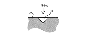
- FIG. 2 is a cross-sectional view showing an example of the shape of the groove.
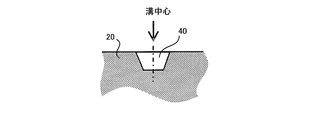
- FIG. 3 is a cross-sectional view showing another example of the shape of the groove.
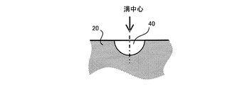
- FIG. 4 is a sectional view showing still another example of the shape of the groove.
- FIG. 5A is a diagram showing the relationship between the position where the groove is provided, the iron loss, the harmonic ratio of the induced voltage, and the cogging torque that affects the torque ripple.
- FIG. 1 is a diagram showing a first embodiment of a rotor for an electric motor according to the present invention.
- FIG. 2 is a cross-sectional view showing an example of the shape of the groove.
- FIG. 3 is a cross-sectional view showing another example of the shape of the groove.
- FIG. 4 is a sectional view showing still another example of the shape of the groove.
- FIG. 5A is a diagram showing the
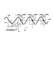
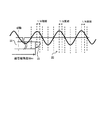
- FIG. 5B is a diagram in which the vicinity of the outer peripheral portion of the rotor core is shown in a straight line, and the waveform of the harmonic component of the induced voltage that is the main component of the torque ripple is superimposed on this.
- FIG. 6 is a partially enlarged view of FIG. 5A.
- FIG. 7 is a diagram showing positions where grooves are provided when the main purpose is to reduce iron loss and cogging torque.
- FIG. 8 is a diagram showing positions where grooves are provided when the main purpose is to reduce the iron loss and the harmonic ratio.
- FIG. 9 is a diagram showing positions where grooves are provided for the purpose of reducing iron loss, reducing cogging torque, and reducing the harmonic ratio.
- FIG. 10 is a view showing a second embodiment of the rotor for an electric motor according to the present invention.
- FIG. 1 is a view showing a first embodiment of a rotor for an electric motor according to the present invention, which is a cross section orthogonal to the rotor shaft and shows 1/8 of the entire circumference (mechanical angle 45 °). The remaining 7/8 has a configuration in which the configuration shown in FIG. 1 is repeatedly arranged in the circumferential direction.
- the motor rotor 1 has a rotor shaft 10, a rotor core 20, and a permanent magnet group 30.
- the rotor shaft 10 is a rotating shaft of the rotor 1.
- the rotor core 20 is provided around the rotor shaft 10.
- the rotor core 20 is formed by laminating a number of electromagnetic steel plates in the axial direction of the rotor shaft 10.
- a group of gaps 21 having a line-symmetric shape around the symmetry axis 2 and a group of gaps 22 parallel to the circumferential direction of the rotor core 20 are formed.
- the gap 21 is formed in a so-called V-shape in which the root portion on the rotor shaft 10 side reaches the symmetry axis 2, and the tip portion moves away from the symmetry axis 2 and approaches the q axis and approaches the rotor outer periphery.
- the gap 22 is formed in the open portion of the V-shaped gap 21 in parallel with the circumferential direction of the rotor core 20.
- the permanent magnet group 30 is embedded in the gap 21 and the gap 22 of the rotor core 20, and a pair of permanent magnets 31 is embedded in one gap 21, and one permanent magnet 32 is embedded in one gap 22. ing.
- the pair of permanent magnets 31 also has a so-called V-shaped arrangement that is line-symmetric with respect to the symmetry axis 2.
- the pair of permanent magnets 31 arranged in the gap 21 and the permanent magnets 32 arranged in the gap 22 form a substantially triangular shape.
- a groove 40 having a groove center is formed on the outer peripheral portion of the rotor core 20 at a later-described position in a region sandwiched by a straight line connecting the outer peripheral side corner 32a of the permanent magnet 32 and the rotor center O and the q axis. .
- FIG. 2 shows an example of the groove 40.
- the groove 40 is a triangle whose cross-sectional shape gradually decreases in width toward the rotor center O, and is formed in line symmetry with respect to a straight line connecting the apex on the rotor center O side and the rotor center O. Therefore, the straight line connecting the apex on the rotor center O side and the rotor center O is the groove center.
- the groove 40 may have a cross-sectional shape of a quadrangle whose width narrows toward the rotor center O as shown in FIG. 3 or an arc shape as shown in FIG. In particular, from the viewpoint of stress dispersion, an arc shape as shown in FIG. 4 is desirable.
- the groove 40 is formed in the above-described region by relaxing the saturation of the magnetic flux interlinking between the distributed winding stator and the rotor 1 arranged on the outer peripheral side of the rotor 1, thereby increasing the iron loss and the induced voltage harmonics. This is to reduce wave components and torque ripple.
- the torque ripple is a torque pulsation during energization, and is generated when there is a difference in magnetic flux passing through the air gap between the rotor 1 and the distributed winding stator disposed on the outer periphery thereof.
- the difference in the ease with which the magnetic flux passes is caused by the difference in the number of magnetic fluxes in the air gap.
- the region sandwiched between the two straight lines connecting the outer peripheral side corner 32a and the rotor center O in the outer peripheral portion of the rotor core 20 is affected by the permanent magnets 32 arranged in the circumferential direction.
- the magnetic flux in the region sandwiched by the straight lines is saturated. Therefore, even if the groove 40 is provided in this region, the magnetic flux interlinking between the distributed winding stator and the rotor 1 does not change. For this reason, iron loss etc. cannot be reduced.
- the “position of the groove 40” refers to the position of the groove center of the groove 40.
- FIG. 5A is a diagram showing the results of examining the relationship between the position where the groove 40 is provided, the iron loss, the harmonic ratio of the induced voltage, and the cogging torque that affects the torque ripple.
- FIG. 5B is a diagram in which the vicinity of the outer peripheral portion of the rotor core 20 that is originally arc-shaped is shown in a straight line, and the waveform of the harmonic component of the induced voltage that is the main component of the torque ripple is superimposed on this.
- the left vertical axis of FIG. 5A is the harmonic ratio of the induced voltage. This is obtained by dividing the peak value of the induced voltage waveform by the peak value of the primary component of the induced voltage waveform, which means the content of the harmonic component in the induced voltage. It means that there are few harmonic components, so that this value is small.
- the right vertical axis of FIG. 5A is the ratio of cogging torque and iron loss to the case without grooves.
- FIG. 5B is a diagram showing the vicinity of the permanent magnet 32 of the rotor core 20, and a solid line A shows a waveform of the main component of the torque ripple.
- the horizontal axis is the electrical angle starting from the d-axis. Further, q1-q11 in FIGS. 5A and 5B indicate the same electrical angle.
- the iron loss is greater in the case where the groove center of the groove 40 is provided at any electrical angle in the q-axis direction from the outer peripheral side corner 32a of the permanent magnet 32 than in the case without the groove. Has been reduced.
- the cogging torque is a point between the outer peripheral side angle 32a of the permanent magnet 32 and the q axis when the point where the outer periphery of the rotor core 20 is engraved for each electrical angle of the torque ripple main component one cycle with the d axis as a base point.
- every point B takes a local minimum value that is almost equivalent to the case without a groove.
- the harmonic ratio of the induced voltage takes a minimum value at an electrical angle shifted from the electrical angle at which the cogging torque takes a minimum value to the d-axis direction side by an electrical angle corresponding to 1/4 of the torque ripple main component. That is, the harmonic ratio also takes a minimum value for each electrical angle of one cycle of the torque ripple main component.
- the effect obtained by providing the groove 40 is obtained because the harmonic component of the magnetic flux interlinking between the distributed winding stator and the rotor 1 is canceled by providing the groove 40 according to the period of the main component of the torque ripple. Conceivable.
- FIG. 6 is an enlarged view of a part of FIG. 5A.
- the electrical angle range in which the cogging torque can be effectively reduced is defined as, for example, the electrical angle range in which the cogging torque is smaller than in the case without grooves. In this case, starting from the electrical angle at which the cogging torque becomes the minimum value, the electrical angle shifted by 1 ⁇ 4 period of the main component of the torque ripple is shifted on the d-axis side, and also shifted by 1/8 period on the q-axis side.
- the electrical angle range that can effectively reduce the cogging torque is up to the electrical angle. As described above, iron loss can also be reduced in this electrical angle range.
- the d-axis side is shifted by a quarter of the torque ripple main component in the same manner as the electrical angle range in which the cogging torque can be effectively reduced with the electrical angle at which the harmonic ratio becomes the minimum value as the base point.
- the range up to the electrical angle up to the electrical angle shifted by 1/8 cycle is also seen on the q-axis side.
- the harmonic ratio is smaller than about 1.02, and it can be said that the harmonic ratio is sufficiently reduced. Therefore, this range is referred to as “an electrical angle range in which the harmonic ratio can be effectively reduced”. In this electrical angle range, iron loss can also be reduced.
- the point B is the base point between the outer peripheral side corner 32a of the permanent magnet 32 and the q axis. If the groove 40 is provided in any part of the range up to the electrical angle shifted by 1 ⁇ 4 cycle of the torque ripple main component on the d-axis side and the electrical angle similarly shifted by 8 cycle on the q-axis side. Good. Although there are three points B in FIG. 7, any point B may be used as a base point. Further, all points B may be used as the base points. The same applies to FIGS. 8 and 9 described later.
- the position shifted from the point B in the d-axis direction by a quarter period of the torque ripple main component is the base point.
- the groove 40 is provided in any part of the range up to the electrical angle shifted by 1/4 cycle of the torque ripple main component on the d-axis side and the electrical angle shifted by 1/8 cycle on the q-axis side. Just do it.
- the electrical angle range when the main purpose is to reduce the cogging torque described above and when the main purpose is to reduce the harmonic ratio is the torque ripple principal component from the point B to the d-axis direction.
- the range up to the electrical angle shifted by 1/8 period of the torque ripple main component overlaps on the q-axis side with the position shifted by 1/4 cycle as a base point. Therefore, within this overlapping electrical angle range, any of the effects of reducing iron loss, reducing cogging torque, and reducing the harmonic ratio can be obtained.
- the position of the groove 40 effective for reducing the above-described iron loss, cogging torque, and harmonic components is expressed by an equation. If it can be generalized by an expression, it can be easily used for design.
- Wm is the angle formed by the rotor outer peripheral side corners of the permanent magnet 32 and the rotor center O
- m is the smallest integer that satisfies m ⁇ (2 ⁇ / n)> Wm / 2.
- n is the torque pull n-th order component.
- each groove 40 is formed. Also good.
- a torque ripple that includes a plurality of harmonic components such as 6th order and 12th order appears.
- the distributed winding stator and the rotor 1 can be easily reduced by a technique called skew that twists in the circumferential direction around the rotation axis.
- skew that twists in the circumferential direction around the rotation axis.
- the main component of the torque ripple of an electric motor generally used for an electric vehicle is the 24th order.
- the opportunity angle corresponding to one cycle of the high-order components becomes small, and it becomes difficult to apply a skew. That is, it is difficult to reduce the main component of torque ripple by skew.
- the groove 40 described above can reduce higher-order components exceeding the 20th order.
- One pole composed of a pair of permanent magnets 31 arranged in a V-shape and a permanent magnet 32 arranged in parallel with the circumferential direction in an open portion of the V-shape is circular with alternating polarity
- grooves 40 described below are provided on the outer periphery of the rotor.
- a base point is between a line connecting the outer peripheral side corner 32a and the rotor shaft center O and the q axis. From there, the groove is within a range sandwiched between a position shifted by 1 ⁇ 4 period of the harmonic component by an electrical angle in the d-axis direction and a position shifted by 1 / period of the harmonic component by an electrical angle in the q-axis direction. Has a center. That is, the groove 40 is provided in the range represented by the above-described formula (1). Thereby, the magnetic loss linked with the stator can be changed to reduce the iron loss. Furthermore, since the cogging torque can be reduced, the torque ripple can be effectively reduced.
- the groove 40 is higher than the line connecting the rotor outer peripheral side corner 32a of the permanent magnet 32 and the rotor shaft center O among the plurality of score lines with the q axis, and is harmonically increased in the d-axis direction by an electrical angle.
- a position where the wave component is shifted by a quarter period is used as a base point, a position where the harmonic component is shifted by a quarter period of the harmonic component in the d-axis direction from that position, and a harmonic component of 1 by an electrical angle in the q-axis direction. / 8.
- the groove 40 is provided in the range represented by the above formula (2). Thereby, the magnetic loss linked with the stator can be changed to reduce the iron loss. Furthermore, the harmonic ratio of the induced voltage, that is, the harmonic component of the induced voltage can be reduced.
- the groove 40 is located between the line that connects the rotor outer peripheral side corner 32a of the permanent magnet 32 and the rotor shaft center O and the q axis among the plurality of scored lines, and is at an electrical angle in the d-axis direction.
- a position shifted by 1/4 period of the harmonic component is used as a base point, and the position is provided within a range from that position to a position shifted by 1/8 period of the harmonic component by an electrical angle in the d-axis direction. That is, the groove 40 is provided in the range represented by the above formula (3). Since this range is an overlapping portion of the range represented by the above-described formula (1) and the range represented by the formula (2), iron loss, harmonic components, and torque ripple can be reduced.
- the basic configuration of the rotor 1 is the same as that of the first embodiment, and only the electrical angle at which the groove 40 is provided is different from that of the first embodiment.
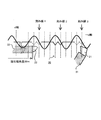
- FIG. 10 is a diagram in which a part of the outer peripheral portion of the rotor core 20 is shown in a straight line as in FIG. 7 and the like, and the waveform A of the main component of the torque ripple is superimposed thereon.
- lines that divide the outer periphery of the rotor core 20 into electrical directions corresponding to one period of the torque ripple principal component in the q-axis direction with the d-axis as a base point are scored line 1, scored line 2, scored line 3 in order from the d-axis side.
- the groove 40 is formed as indicated by the solid line S, for example, within the electrical angle range represented by the expression (1) with the score line 2 being the center of the groove and the score line 2 as the center.
- the main purpose is to reduce the harmonic ratio of the induced voltage
- the electrical angle shifted from the score line 2 to the d-axis side by 1 ⁇ 4 period of the torque ripple main component is set to the groove center, and the equation (2)
- the groove 40 is formed within the electrical angle range represented by
- the q-axis side 1/1 of the torque ripple principal component is located at the position shifted from the score line 2 by a quarter period of the torque ripple principal component in the d-axis direction.
- the groove 40 is formed within the electric angle range represented by the expression (3) with the electrical angle shifted by eight cycles as the groove center. Of course, you may form in the position of both the continuous line S and the continuous line T.
- the position of the groove 40 is determined based on the score line 2 for any purpose.
- m is the minimum integer + 1 that satisfies m ⁇ (2 ⁇ / n)> Wm / 2.
- the permanent magnet 31 arranged in a V shape is embedded in the gap 21, and the permanent magnet 32 arranged along the circumferential direction is embedded in the gap 22.
- a centrifugal force acts on the permanent magnet 31 and the permanent magnet 32. Therefore, the outer peripheral side vicinity of the space
- the strength against the centrifugal force of the rotor core 20 at the position where the groove 40 is provided decreases as the distance between the groove 40 and the air gap 21 and the air gap 22 decreases.
- FIG. 10 an example in which the groove 40 is provided in the electrical angle range of the above formula (1) with the score line 1 as a reference is indicated by a broken line U and a broken line V.
- the broken line U is a groove 40 centered on the position of the score line 1
- the broken line V is a groove 40 centered on the position shifted from the score line 1 to the d-axis side by a quarter period of the torque ripple principal component. It is.
- the groove 40 is provided at the position of the broken line U and the broken line V, the strength against the centrifugal force is reduced at the portion between the groove 40 and the gap 22, and the strength against the centrifugal force is insufficient depending on the position of the gap 22, In order to suppress the centrifugal force, it is necessary to limit the rotation speed of the electric motor.
- the groove 40 centered on the position of the score line 3 as shown by the broken line W in FIG. 10 and the d-axis side from the score line 3 by 1/4 period of the torque ripple principal component as shown by the broken line X.
- the groove 40 centered on the offset position. In this case, there is a possibility that the strength against the centrifugal force is reduced between the groove 40 and the gap 21 as described above.
- the groove 40 is provided in the electrical angle range based on the score line 2 of the present embodiment, that is, the position indicated by the solid line S and the solid line T, the groove 40 is formed from either the gap 21 or the gap 22. Since the distance is sufficiently large, the strength against the centrifugal force that affects the rotation speed of the electric motor as described above is not reduced.
- the one closest to the q-axis direction from the line connecting the rotor outer peripheral corner 32a of the permanent magnet 32 and the rotor shaft center O is used as a base point, or the d-axis direction from this score line
- the groove 40 is provided at a base point at a position shifted by a quarter period of the harmonic component at the electrical angle.
Landscapes
- Engineering & Computer Science (AREA)
- Power Engineering (AREA)
- Permanent Field Magnets Of Synchronous Machinery (AREA)
- Permanent Magnet Type Synchronous Machine (AREA)
- Iron Core Of Rotating Electric Machines (AREA)
Abstract
Description
図1は本発明による電動機用ロータの第1実施形態を示す図であり、ロータシャフトに直交する断面であって、全周の1/8(機械角45°)を示す。なお、残りの7/8は、図1に示した構成を周方向に繰り返し並べた構成となっている。
m×(2π/n)-(2π/n)/4 ・・・(1)
(m-1/4)×(2π/n)-(2π/n)/4 ・・・(2)
(m-1/4)×(2π/n) ・・・(3)
本実施形態は、ロータ1の基本的な構成は第1実施形態と同様であり、溝40を設ける電気角度だけが第1実施形態と異なる。
Claims (8)
- ロータシャフトと、
外周方向に開くV字型に配置された一対の第1永久磁石及び前記V字型の開いた部分に周方向と平行に配置された第2永久磁石で構成される一極が、交互に極性を変えて円周方向に複数配置されたロータコアと、
を備え、
前記ロータコア外周のd軸からq軸までを誘起電圧の高調波成分1周期分の電気角度間隔で刻んだ複数の刻み点と前記ロータシャフト中心とを結ぶ複数の刻み線のうち、前記第2永久磁石のロータ外周側角部と前記ロータシャフト中心とを結ぶ線とq軸との間にあるものを基点として、当該基点からd軸方向に電気角度で前記高調波成分の1/4周期分ずれた位置と、q軸方向に電気角度で前記高調波成分の1/8周期分ずれた位置とで挟まれる範囲内に溝中心を有する溝を形成したことを特徴とする電動機用ロータ。 - ロータシャフトと、
外周方向に開くV字型に配置された一対の第1永久磁石及び前記V字型の開いた部分に周方向と平行に配置された第2永久磁石で構成される一極が、交互に極性を変えて円周方向に複数配置されたロータコアと、
を備え、
前記ロータコア外周のd軸からq軸までを誘起電圧の高調波成分1周期分の電気角度間隔で刻んだ複数の刻み点と前記ロータシャフト中心とを結ぶ複数の刻み線のうち、前記第2永久磁石のロータ外周側角部と前記ロータシャフト中心とを結ぶ線とq軸との間にあるものから、d軸方向に電気角度で前記高調波成分の1/4周期分ずれた位置を基点として、当該基点からd軸方向に電気角度で前記高調波成分の1/4周期分ずれた位置と、q軸方向に電気角度で前記高調波成分の1/8周期分ずれた位置とで挟まれる範囲内に溝中心を有する溝を形成したことを特徴とする電動機用ロータ。 - ロータシャフトと、
外周方向に開くV字型に配置された一対の第1永久磁石及び前記V字型の開いた部分に周方向と平行に配置された第2永久磁石で構成される一極が、交互に極性を変えて円周方向に複数配置されたロータコアと、
を備え、
前記ロータコア外周のd軸からq軸までを誘起電圧の高調波成分1周期分の電気角度間隔で刻んだ複数の刻み点と前記ロータシャフト中心とを結ぶ複数の刻み線のうち、前記第2永久磁石のロータ外周側角部と前記ロータシャフト中心とを結ぶ線とq軸との間にあるものから、d軸方向に電気角度で前記高調波成分の1/4周期分ずれた位置を基点として、当該基点からq軸方向に電気角度で前記高調波成分の1/8周期分ずれた位置までの範囲内に溝中心を有する溝を形成したことを特徴とする電動機用ロータ。 - 請求項1に記載の電動機用ロータにおいて、
誘起電圧の高調波成分の次数をn、前記ロータシャフト中心と前記第2永久磁石の2つのロータ外周側角部とを結ぶ直線のなす角度をWm、m×(2π/n)>Wm/2を満足する最小の整数からn/4の商までの整数をm、としたときに、前記溝中心を設ける範囲が、m×(2π/n)-(2π/n)/4からm×(2π/n)+(2π/n)/8で表される電動機用ロータ。 - 請求項2に記載の電動機用ロータにおいて、
誘起電圧の高調波成分の次数をn、前記ロータシャフト中心と前記第2永久磁石の2つのロータ外周側角部とを結ぶ直線のなす角度をWm、m×(2π/n)>Wm/2を満足する最小の整数からn/4の商までの整数をm、としたときに、前記溝中心を設ける範囲が、(m-1/4)×(2π/n)-(2π/n)/4から(m-1/4)×(2π/n)+(2π/n)/8で表される電動機用ロータ。 - 請求項3に記載の電動機用ロータにおいて、
誘起電圧の高調波成分の次数をn、前記ロータシャフト中心と前記第2永久磁石の2つのロータ外周側角部とを結ぶ直線のなす角度をWm、m×(2π/n)>Wm/2を満足する最小の整数からn/4の商までの整数をm、としたときに、前記溝中心を設ける範囲が、(m-1/4)×(2π/n)から(m-1/4)×(2π/n)+(2π/n)/8で表される電動機用ロータ。 - 請求項1または請求項4に記載の電動機用ロータにおいて、
前記複数の刻み線のうち、前記第2永久磁石のロータ外周側角と前記ロータシャフト中心とを結ぶ線からq軸方向に2番目に近いものを基点とする電動機用ロータ。 - 請求項2、請求項3、請求項5、または請求項6に記載の電動機用ロータにおいて、
前記複数の刻み線のうち、前記第2永久磁石のロータ外周側角と前記ロータシャフト中心とを結ぶ線からq軸方向に2番目に近いものから、d軸方向に電気角度で前記高調波成分の1/4周期分ずれた位置を基点とする電動機用ロータ。
Priority Applications (6)
| Application Number | Priority Date | Filing Date | Title |
|---|---|---|---|
| CN201180036851.6A CN103026586B (zh) | 2010-07-27 | 2011-07-19 | 电动机用转子 |
| US13/812,076 US9083217B2 (en) | 2010-07-27 | 2011-07-19 | Rotor for electric motor |
| MX2013001030A MX2013001030A (es) | 2010-07-27 | 2011-07-19 | Rotor para motor electrico. |
| EP11812320.7A EP2600498B1 (en) | 2010-07-27 | 2011-07-19 | Rotor for electric motor |
| RU2013108505/07A RU2533190C2 (ru) | 2010-07-27 | 2011-07-19 | Ротор для электромотора |
| JP2012526438A JP5516739B2 (ja) | 2010-07-27 | 2011-07-19 | 電動機用ロータ |
Applications Claiming Priority (2)
| Application Number | Priority Date | Filing Date | Title |
|---|---|---|---|
| JP2010-168050 | 2010-07-27 | ||
| JP2010168050 | 2010-07-27 |
Publications (1)
| Publication Number | Publication Date |
|---|---|
| WO2012014728A1 true WO2012014728A1 (ja) | 2012-02-02 |
Family
ID=45529944
Family Applications (1)
| Application Number | Title | Priority Date | Filing Date |
|---|---|---|---|
| PCT/JP2011/066373 Ceased WO2012014728A1 (ja) | 2010-07-27 | 2011-07-19 | 電動機用ロータ |
Country Status (7)
| Country | Link |
|---|---|
| US (1) | US9083217B2 (ja) |
| EP (1) | EP2600498B1 (ja) |
| JP (1) | JP5516739B2 (ja) |
| CN (1) | CN103026586B (ja) |
| MX (1) | MX2013001030A (ja) |
| RU (1) | RU2533190C2 (ja) |
| WO (1) | WO2012014728A1 (ja) |
Cited By (5)
| Publication number | Priority date | Publication date | Assignee | Title |
|---|---|---|---|---|
| JP2013225997A (ja) * | 2012-04-23 | 2013-10-31 | Hitachi Automotive Systems Ltd | 永久磁石回転電機及びそれを用いた電動車両 |
| WO2014104820A1 (ko) * | 2012-12-28 | 2014-07-03 | 주식회사 효성 | 모터의 회전자 |
| CN105914994A (zh) * | 2016-05-12 | 2016-08-31 | 张学义 | 电动汽车电磁与内置永磁隐形磁极驱动电机 |
| WO2017077580A1 (ja) * | 2015-11-02 | 2017-05-11 | 三菱電機株式会社 | 電動機、ロータ、圧縮機および冷凍空調装置 |
| GB2551537A (en) * | 2016-06-21 | 2017-12-27 | Jaguar Land Rover Ltd | Electrical machine |
Families Citing this family (21)
| Publication number | Priority date | Publication date | Assignee | Title |
|---|---|---|---|---|
| KR20150078467A (ko) | 2013-12-30 | 2015-07-08 | 현대자동차주식회사 | 매입형 영구자석 모터의 회전자 |
| CN105186741A (zh) * | 2014-05-27 | 2015-12-23 | 比亚迪股份有限公司 | 电机转子和具有其的电机 |
| JP6062900B2 (ja) * | 2014-09-15 | 2017-01-18 | トヨタ自動車株式会社 | ロータの製造方法 |
| JP2016082696A (ja) * | 2014-10-16 | 2016-05-16 | アイシン精機株式会社 | 埋込磁石型モータおよび埋込磁石型モータのロータ |
| CN104600939A (zh) * | 2015-02-04 | 2015-05-06 | 广东美芝制冷设备有限公司 | 永磁同步电机及具有其的压缩机 |
| CN104882978B (zh) * | 2015-05-07 | 2018-03-20 | 东南大学 | 一种低转矩脉动高效率永磁电机定转子结构 |
| GB201510273D0 (en) | 2015-06-12 | 2015-07-29 | Jaguar Land Rover Ltd | Electric drive motor |
| US10483816B2 (en) * | 2015-10-30 | 2019-11-19 | Mitsubishi Electric Corporation | Motor, rotor, compressor, and refrigeration and air conditioning apparatus |
| CN106026588A (zh) * | 2016-05-13 | 2016-10-12 | 山东理工大学 | 带真空泵的永磁与电磁并联磁路混合励磁发电机 |
| CN105914998A (zh) * | 2016-05-13 | 2016-08-31 | 山东理工大学 | 内嵌双径向永磁与凸极电磁混合励磁驱动电机 |
| FR3059849B1 (fr) * | 2016-12-01 | 2019-05-17 | Institut Vedecom | Machine electrique comportant un rotor a aimants permanents interieurs inclines |
| DE102017208280A1 (de) * | 2017-05-17 | 2018-11-22 | BSH Hausgeräte GmbH | Elektrischer Antriebsmotor mit verringerter Geräuschentwicklung sowie diesen enthaltendes Haushaltsgerät |
| JP6821022B2 (ja) * | 2017-06-19 | 2021-01-27 | 日産自動車株式会社 | 回転電機の回転子 |
| JP6879140B2 (ja) * | 2017-09-15 | 2021-06-02 | トヨタ自動車株式会社 | 回転電機 |
| JP6606157B2 (ja) | 2017-11-15 | 2019-11-13 | ファナック株式会社 | ロータおよび回転電機 |
| CN108616180A (zh) * | 2018-07-23 | 2018-10-02 | 杨世国 | 一种组合式永磁转子 |
| KR102654530B1 (ko) * | 2018-12-27 | 2024-04-03 | 현대자동차주식회사 | 매입형 영구자석 전동기 및 이에 포함되는 회전자 |
| KR102750665B1 (ko) * | 2019-10-11 | 2025-01-06 | 현대자동차주식회사 | 비대칭 회전자 코어를 갖는 모터 |
| JP7484465B2 (ja) * | 2020-06-12 | 2024-05-16 | ニデック株式会社 | 回転電機 |
| JP7632471B2 (ja) * | 2020-08-31 | 2025-02-19 | ニデック株式会社 | 回転電機 |
| JP2024029631A (ja) | 2022-08-22 | 2024-03-06 | 山洋電気株式会社 | 回転子 |
Citations (6)
| Publication number | Priority date | Publication date | Assignee | Title |
|---|---|---|---|---|
| JP2004328956A (ja) | 2003-04-28 | 2004-11-18 | Toyota Motor Corp | 電動機 |
| JP2006014457A (ja) * | 2004-06-24 | 2006-01-12 | Fanuc Ltd | 同期電動機 |
| JP2006314152A (ja) * | 2005-05-06 | 2006-11-16 | Nissan Motor Co Ltd | 永久磁石型電動機 |
| JP2008206308A (ja) * | 2007-02-20 | 2008-09-04 | Toyota Industries Corp | 永久磁石式回転電機 |
| WO2008150035A1 (ja) * | 2007-06-07 | 2008-12-11 | Toyota Jidosha Kabushiki Kaisha | 回転電機 |
| JP2010168050A (ja) | 2009-01-20 | 2010-08-05 | Nishida Seikan Kk | 物品の支持枠体 |
Family Cites Families (7)
| Publication number | Priority date | Publication date | Assignee | Title |
|---|---|---|---|---|
| JP3308828B2 (ja) * | 1996-10-18 | 2002-07-29 | 株式会社日立製作所 | 永久磁石回転電機及びそれを用いた電動車両 |
| NO311200B1 (no) * | 1999-05-25 | 2001-10-22 | Smart Motor As | Elektrisk maskin |
| US6563246B1 (en) * | 1999-10-14 | 2003-05-13 | Denso Corporation | Rotary electric machine for electric vehicle |
| JP2002305859A (ja) * | 2001-03-30 | 2002-10-18 | Aisin Aw Co Ltd | 永久磁石式同期電動機 |
| US8405270B2 (en) * | 2007-05-07 | 2013-03-26 | Panasonic Corporation | Permanent magnet buried type electric motor |
| JP4900069B2 (ja) * | 2007-06-13 | 2012-03-21 | トヨタ自動車株式会社 | 回転電機 |
| JP2009219331A (ja) * | 2008-03-13 | 2009-09-24 | Hitachi Ltd | 永久磁石式ジェネレータとそれを用いたハイブリッド車両 |
-
2011
- 2011-07-19 US US13/812,076 patent/US9083217B2/en active Active
- 2011-07-19 WO PCT/JP2011/066373 patent/WO2012014728A1/ja not_active Ceased
- 2011-07-19 EP EP11812320.7A patent/EP2600498B1/en active Active
- 2011-07-19 CN CN201180036851.6A patent/CN103026586B/zh active Active
- 2011-07-19 MX MX2013001030A patent/MX2013001030A/es active IP Right Grant
- 2011-07-19 RU RU2013108505/07A patent/RU2533190C2/ru active
- 2011-07-19 JP JP2012526438A patent/JP5516739B2/ja active Active
Patent Citations (6)
| Publication number | Priority date | Publication date | Assignee | Title |
|---|---|---|---|---|
| JP2004328956A (ja) | 2003-04-28 | 2004-11-18 | Toyota Motor Corp | 電動機 |
| JP2006014457A (ja) * | 2004-06-24 | 2006-01-12 | Fanuc Ltd | 同期電動機 |
| JP2006314152A (ja) * | 2005-05-06 | 2006-11-16 | Nissan Motor Co Ltd | 永久磁石型電動機 |
| JP2008206308A (ja) * | 2007-02-20 | 2008-09-04 | Toyota Industries Corp | 永久磁石式回転電機 |
| WO2008150035A1 (ja) * | 2007-06-07 | 2008-12-11 | Toyota Jidosha Kabushiki Kaisha | 回転電機 |
| JP2010168050A (ja) | 2009-01-20 | 2010-08-05 | Nishida Seikan Kk | 物品の支持枠体 |
Cited By (12)
| Publication number | Priority date | Publication date | Assignee | Title |
|---|---|---|---|---|
| JP2013225997A (ja) * | 2012-04-23 | 2013-10-31 | Hitachi Automotive Systems Ltd | 永久磁石回転電機及びそれを用いた電動車両 |
| WO2014104820A1 (ko) * | 2012-12-28 | 2014-07-03 | 주식회사 효성 | 모터의 회전자 |
| KR101426168B1 (ko) | 2012-12-28 | 2014-08-04 | 주식회사 효성 | 모터의 회전자 |
| WO2017077580A1 (ja) * | 2015-11-02 | 2017-05-11 | 三菱電機株式会社 | 電動機、ロータ、圧縮機および冷凍空調装置 |
| JPWO2017077580A1 (ja) * | 2015-11-02 | 2018-03-08 | 三菱電機株式会社 | 電動機、ロータ、圧縮機および冷凍空調装置 |
| GB2559495A (en) * | 2015-11-02 | 2018-08-08 | Mitsubishi Electric Corp | Electric motor, rotor, compressor and refrigerating air-conditioner |
| US11018535B2 (en) | 2015-11-02 | 2021-05-25 | Mitsubishi Electric Corporation | Motor, rotor, compressor, and refrigeration and air conditioning apparatus |
| GB2559495B (en) * | 2015-11-02 | 2021-12-29 | Mitsubishi Electric Corp | Motor, rotor, compressor, and refrigeration and air conditioning apparatus |
| CN105914994A (zh) * | 2016-05-12 | 2016-08-31 | 张学义 | 电动汽车电磁与内置永磁隐形磁极驱动电机 |
| GB2551537A (en) * | 2016-06-21 | 2017-12-27 | Jaguar Land Rover Ltd | Electrical machine |
| US11223250B2 (en) | 2016-06-21 | 2022-01-11 | Jaguar Land Rover Limited | Electrical machine |
| US11757316B2 (en) | 2016-06-21 | 2023-09-12 | Jaguar Land Rover Limited | Electrical machine |
Also Published As
| Publication number | Publication date |
|---|---|
| EP2600498B1 (en) | 2018-09-12 |
| US20130154425A1 (en) | 2013-06-20 |
| US9083217B2 (en) | 2015-07-14 |
| RU2013108505A (ru) | 2014-09-10 |
| JPWO2012014728A1 (ja) | 2013-09-12 |
| EP2600498A4 (en) | 2018-03-28 |
| EP2600498A1 (en) | 2013-06-05 |
| RU2533190C2 (ru) | 2014-11-20 |
| JP5516739B2 (ja) | 2014-06-11 |
| MX2013001030A (es) | 2013-03-22 |
| CN103026586A (zh) | 2013-04-03 |
| CN103026586B (zh) | 2015-11-25 |
Similar Documents
| Publication | Publication Date | Title |
|---|---|---|
| JP5516739B2 (ja) | 電動機用ロータ | |
| JP6620097B2 (ja) | 永久磁石モータ | |
| JP5696820B2 (ja) | 永久磁石モータの回転子 | |
| JP5609976B2 (ja) | 回転電機用ローター | |
| CN103339829B (zh) | 无刷电动机以及搭载该无刷电动机的电气设备 | |
| US9059621B2 (en) | Electric rotating machine | |
| JP5811565B2 (ja) | 回転子および永久磁石電動機 | |
| JP5353962B2 (ja) | 永久磁石型電動機 | |
| US20130106226A1 (en) | Electric rotating machine | |
| JP6821022B2 (ja) | 回転電機の回転子 | |
| US20130106227A1 (en) | Electric rotating machine | |
| JP5609844B2 (ja) | 電動機 | |
| WO2017171037A1 (ja) | ロータ及びロータの設計方法 | |
| WO2017154287A1 (ja) | 回転電機 | |
| JP6760014B2 (ja) | 回転電機 | |
| WO2021095167A1 (ja) | 回転電機 | |
| JP6584968B2 (ja) | 回転電機 | |
| JP2015050803A (ja) | 回転電機 | |
| JP2021106474A (ja) | 回転電機の回転子及び回転電機 | |
| JP7643269B2 (ja) | 回転子 | |
| CN203456960U (zh) | 电机转子、永磁式旋转电机及具有其的压缩机 | |
| JP5491344B2 (ja) | モータ | |
| JP6382085B2 (ja) | 回転電機の回転子及びそれを用いた回転電機 | |
| JP2011083114A (ja) | 電動機 |
Legal Events
| Date | Code | Title | Description |
|---|---|---|---|
| WWE | Wipo information: entry into national phase |
Ref document number: 201180036851.6 Country of ref document: CN |
|
| 121 | Ep: the epo has been informed by wipo that ep was designated in this application |
Ref document number: 11812320 Country of ref document: EP Kind code of ref document: A1 |
|
| DPE1 | Request for preliminary examination filed after expiration of 19th month from priority date (pct application filed from 20040101) | ||
| WWE | Wipo information: entry into national phase |
Ref document number: 13812076 Country of ref document: US |
|
| WWE | Wipo information: entry into national phase |
Ref document number: 2012526438 Country of ref document: JP Ref document number: MX/A/2013/001030 Country of ref document: MX |
|
| NENP | Non-entry into the national phase |
Ref country code: DE |
|
| WWE | Wipo information: entry into national phase |
Ref document number: 2011812320 Country of ref document: EP |
|
| ENP | Entry into the national phase |
Ref document number: 2013108505 Country of ref document: RU Kind code of ref document: A |
|
| REG | Reference to national code |
Ref country code: BR Ref legal event code: B01A Ref document number: 112013003479 Country of ref document: BR |
|
| ENPW | Started to enter national phase and was withdrawn or failed for other reasons |
Ref document number: 112013003479 Country of ref document: BR Free format text: PEDIDO RETIRADO EM RELACAO AO BRASIL, TENDO EM VISTA A NAO ACEITACAO DA ENTRADA NA FASE NACIONAL FACE A INTEMPESTIVIDADE, POIS O PRAZO PARA A REFERIDA ENTRADA EXPIRAVA EM 28/01/2013 (30 MESES CONTADOS DA DATA DE PRIORIDADE) E A ENTRADA SO OCORREU EM 29/01/2013. |