WO2012014793A1 - リチウムイオン二次電池 - Google Patents
リチウムイオン二次電池 Download PDFInfo
- Publication number
- WO2012014793A1 WO2012014793A1 PCT/JP2011/066657 JP2011066657W WO2012014793A1 WO 2012014793 A1 WO2012014793 A1 WO 2012014793A1 JP 2011066657 W JP2011066657 W JP 2011066657W WO 2012014793 A1 WO2012014793 A1 WO 2012014793A1
- Authority
- WO
- WIPO (PCT)
- Prior art keywords
- active material
- electrode active
- positive electrode
- negative electrode
- secondary battery
- Prior art date
- Legal status (The legal status is an assumption and is not a legal conclusion. Google has not performed a legal analysis and makes no representation as to the accuracy of the status listed.)
- Ceased
Links
Images
Classifications
-
- H—ELECTRICITY
- H01—ELECTRIC ELEMENTS
- H01M—PROCESSES OR MEANS, e.g. BATTERIES, FOR THE DIRECT CONVERSION OF CHEMICAL ENERGY INTO ELECTRICAL ENERGY
- H01M4/00—Electrodes
- H01M4/02—Electrodes composed of, or comprising, active material
- H01M4/36—Selection of substances as active materials, active masses, active liquids
- H01M4/48—Selection of substances as active materials, active masses, active liquids of inorganic oxides or hydroxides
- H01M4/485—Selection of substances as active materials, active masses, active liquids of inorganic oxides or hydroxides of mixed oxides or hydroxides for inserting or intercalating light metals, e.g. LiTi2O4 or LiTi2OxFy
-
- H—ELECTRICITY
- H01—ELECTRIC ELEMENTS
- H01M—PROCESSES OR MEANS, e.g. BATTERIES, FOR THE DIRECT CONVERSION OF CHEMICAL ENERGY INTO ELECTRICAL ENERGY
- H01M10/00—Secondary cells; Manufacture thereof
- H01M10/05—Accumulators with non-aqueous electrolyte
- H01M10/052—Li-accumulators
- H01M10/0525—Rocking-chair batteries, i.e. batteries with lithium insertion or intercalation in both electrodes; Lithium-ion batteries
-
- H—ELECTRICITY
- H01—ELECTRIC ELEMENTS
- H01M—PROCESSES OR MEANS, e.g. BATTERIES, FOR THE DIRECT CONVERSION OF CHEMICAL ENERGY INTO ELECTRICAL ENERGY
- H01M4/00—Electrodes
- H01M4/02—Electrodes composed of, or comprising, active material
- H01M4/36—Selection of substances as active materials, active masses, active liquids
- H01M4/48—Selection of substances as active materials, active masses, active liquids of inorganic oxides or hydroxides
- H01M4/50—Selection of substances as active materials, active masses, active liquids of inorganic oxides or hydroxides of manganese
- H01M4/505—Selection of substances as active materials, active masses, active liquids of inorganic oxides or hydroxides of manganese of mixed oxides or hydroxides containing manganese for inserting or intercalating light metals, e.g. LiMn2O4 or LiMn2OxFy
-
- H—ELECTRICITY
- H01—ELECTRIC ELEMENTS
- H01M—PROCESSES OR MEANS, e.g. BATTERIES, FOR THE DIRECT CONVERSION OF CHEMICAL ENERGY INTO ELECTRICAL ENERGY
- H01M4/00—Electrodes
- H01M4/02—Electrodes composed of, or comprising, active material
- H01M4/62—Selection of inactive substances as ingredients for active masses, e.g. binders, fillers
- H01M4/621—Binders
- H01M4/622—Binders being polymers
-
- H—ELECTRICITY
- H01—ELECTRIC ELEMENTS
- H01M—PROCESSES OR MEANS, e.g. BATTERIES, FOR THE DIRECT CONVERSION OF CHEMICAL ENERGY INTO ELECTRICAL ENERGY
- H01M4/00—Electrodes
- H01M4/02—Electrodes composed of, or comprising, active material
- H01M4/62—Selection of inactive substances as ingredients for active masses, e.g. binders, fillers
- H01M4/624—Electric conductive fillers
- H01M4/625—Carbon or graphite
-
- H—ELECTRICITY
- H01—ELECTRIC ELEMENTS
- H01M—PROCESSES OR MEANS, e.g. BATTERIES, FOR THE DIRECT CONVERSION OF CHEMICAL ENERGY INTO ELECTRICAL ENERGY
- H01M4/00—Electrodes
- H01M4/02—Electrodes composed of, or comprising, active material
- H01M4/64—Carriers or collectors
- H01M4/66—Selection of materials
- H01M4/661—Metal or alloys, e.g. alloy coatings
-
- Y—GENERAL TAGGING OF NEW TECHNOLOGICAL DEVELOPMENTS; GENERAL TAGGING OF CROSS-SECTIONAL TECHNOLOGIES SPANNING OVER SEVERAL SECTIONS OF THE IPC; TECHNICAL SUBJECTS COVERED BY FORMER USPC CROSS-REFERENCE ART COLLECTIONS [XRACs] AND DIGESTS
- Y02—TECHNOLOGIES OR APPLICATIONS FOR MITIGATION OR ADAPTATION AGAINST CLIMATE CHANGE
- Y02E—REDUCTION OF GREENHOUSE GAS [GHG] EMISSIONS, RELATED TO ENERGY GENERATION, TRANSMISSION OR DISTRIBUTION
- Y02E60/00—Enabling technologies; Technologies with a potential or indirect contribution to GHG emissions mitigation
- Y02E60/10—Energy storage using batteries
-
- Y—GENERAL TAGGING OF NEW TECHNOLOGICAL DEVELOPMENTS; GENERAL TAGGING OF CROSS-SECTIONAL TECHNOLOGIES SPANNING OVER SEVERAL SECTIONS OF THE IPC; TECHNICAL SUBJECTS COVERED BY FORMER USPC CROSS-REFERENCE ART COLLECTIONS [XRACs] AND DIGESTS
- Y02—TECHNOLOGIES OR APPLICATIONS FOR MITIGATION OR ADAPTATION AGAINST CLIMATE CHANGE
- Y02T—CLIMATE CHANGE MITIGATION TECHNOLOGIES RELATED TO TRANSPORTATION
- Y02T10/00—Road transport of goods or passengers
- Y02T10/60—Other road transportation technologies with climate change mitigation effect
- Y02T10/70—Energy storage systems for electromobility, e.g. batteries
Definitions
- This embodiment relates to a lithium ion secondary battery. More specifically, the present invention relates to a lithium ion secondary battery having high energy density and excellent quick charge characteristics.
- lithium ion secondary batteries As energy sources is increasing rapidly as technology development and demand for mobile devices increase. Recently, the use of lithium ion secondary batteries as a power source in electric vehicles (EV), hybrid electric vehicles (HEV), etc. has become a reality. In recent years, a lot of research has been conducted on lithium ion secondary batteries that can meet various requirements, and in particular, the development of lithium ion secondary batteries that are inexpensive, have high energy density, and have rapid charging characteristics has been rushed. It is.
- a lithium ion secondary battery has a configuration in which a positive electrode and a negative electrode are opposed to each other via a separator.
- the positive electrode and the negative electrode are respectively composed of a positive electrode current collector and a positive electrode active material, and a negative electrode current collector and a negative electrode active material.
- Each of these elements is impregnated with a non-aqueous electrolyte solution.
- the lithium ion secondary battery is charged or discharged, the lithium ions dissolved in the electrolyte solution pass between the separator and move between the positive electrode and the negative electrode, and the lithium ion secondary material has lithium ion in the positive electrode active material and the negative electrode active material, respectively. Occlusion and release are performed. This operates as a battery.
- a negative electrode active material used for a lithium ion secondary battery a material that occludes and releases lithium ions such as a carbon material, aluminum (Al), silicon (Si), tin (which forms an alloy with lithium (Li), tin (A metal material such as Sn) is used.
- Li 4/3 Ti 5/3 O 4 has a reduction potential as high as about 1.5 V with respect to Li / Li + , and can suppress reductive decomposition of the non-aqueous electrolyte on the negative electrode surface, and is due to the spinel structure. Because of the stability of the crystal structure, it is possible to suppress the deterioration of quick charge characteristics caused by the negative electrode and the non-aqueous electrolyte, so that it has been put to practical use.
- LiCoO 2 lithium cobalt oxide
- a positive electrode active material based on Ni, Mn, or Fe that is abundant on the earth and that is inexpensive such as lithium iron phosphate (LiFePO 4 ), lithium nickelate (LiNiO 2 ),
- LiMn 2 O 4 lithium manganate
- LiFePO 4 has an olivine structure and is fixed by covalently bonding oxygen with an element other than iron, so that it does not release oxygen even at high temperatures, and LiCoO 2 , LiNiO 2 , LiMn 2 O It can be inferred that the safety of the battery can be improved as compared with a positive electrode active material such as 4 .
- the electrical conductivity of LiFePO 4 is about 10 ⁇ 9 S / cm, which is significantly lower than the electrical conductivity of LiMn 2 O 4 and LiNiO 2 of 10 ⁇ 5 S / cm. Yes.
- a problem that the operating voltage is as low as about 3.3 V with respect to Li / Li + is also pointed out.
- LiNiO 2 has a large theoretical capacity per unit weight of 274 mAhg ⁇ 1 , is attractive as a battery active material, and is the most promising material for practical use as a power source for electric vehicles.
- LiNiO 2 has a layered rock salt structure ( ⁇ -NaFeO 2 structure) like LiCoO 2 , an oxygen layer having a large electronegativity is adjacent due to lithium detachment during charging. For this reason, it is necessary to limit the amount of lithium extracted during actual use, and if too much lithium is extracted, such as in an overcharged state, the structure will change due to electrostatic repulsion between oxygen layers and heat will be generated. There is much room for improvement. Since a large protection circuit is required outside in order to ensure the safety of the battery, the energy density is lowered.
- LiMn 2 O 4 Since LiMn 2 O 4 has a positive spinel structure and has a space group Fd3m, it has a high potential equivalent to 4V class LiCoO 2 with respect to the lithium electrode, is easily synthesized, and has a high battery capacity. Therefore, it has attracted attention as a very promising material and has been put into practical use.
- LiMn 2 O 4 is an excellent material as described above, but has a problem that the capacity deterioration during storage at high temperature is large and Mn is dissolved in the electrolytic solution, so that the rapid charge characteristic is not sufficient. This is due to the instability of trivalent Mn. When the average valence of Mn ions changes between trivalent and tetravalent, Jahn-Teller distortion occurs in the crystal, It is considered that the performance deterioration accompanying the decrease in the stability of the crystal structure occurs.
- Patent Document 1 discloses a secondary battery including such a positive electrode active material, and discloses a positive electrode active material in which trivalent Mn contained in LiMn 2 O 4 is substituted with another metal. That is, Patent Document 1 has a spinel structure and a composition formula LiM x Mn 2 ⁇ x O 4 (M is Al, B, Cr, Co, Ni, Ti, Fe, Mg, Ba, Zn, Ge, Nb).
- M is Al, B, Cr, Co, Ni, Ti, Fe, Mg, Ba, Zn, Ge, Nb.
- a secondary battery including one or more selected lithium-manganese composite oxides represented by 0.01 ⁇ x ⁇ 1) is described. Also, examples of using LiMn 1.75 Al 0.25 O 4 as the positive electrode active material is specifically disclosed.
- LiMn 2 O 4 undergoes the following Mn valence change with charge / discharge.
- LiMn 2 O 4 contains trivalent Mn and tetravalent Mn, and discharge occurs when trivalent Mn of these changes to tetravalent. Therefore, substituting trivalent Mn with other elements inevitably results in a reduction in discharge capacity. That is, even if the structural stability of the positive electrode active material is improved to improve the reliability of the battery, the discharge capacity is remarkably reduced, and it is difficult to achieve both. In particular, it is very difficult to obtain a positive electrode active material having a discharge capacity value of 130 mAh / g or more and high reliability.
- the positive electrode active material in which trivalent Mn contained in LiMn 2 O 4 is substituted with another metal as described above constitutes a lithium secondary battery having a so-called 4V class electromotive force.
- a part of Mn of LiMn 2 O 4 is replaced with Ni, Co, Fe, Cu, Cr, etc., and the charge / discharge potential is increased. Studies have been made to increase the energy density.
- These constitute a lithium secondary battery having a so-called 5V class electromotive force.
- description will be given by taking LiNi 0.5 Mn 1.5 O 4 as an example.
- LiNi 0.5 Mn 1.5 O 4 causes the following Ni valence change with charge / discharge.
- LiNi 0.5 Mn 1.5 O 4 discharges when divalent Ni changes to tetravalent. There is no valence change for Mn.
- a high electromotive force of 4.5 V or more can be obtained by replacing the metal involved in charge / discharge from Mn to Ni, Co, or the like.
- Patent Document 2 as a positive electrode active material, a spinel crystal LiMn 2-yz Ni y M z O 4 that charges and discharges at a potential of 4.5 V or more with respect to Li metal (provided that M: At least one selected from the group consisting of Fe, Co, Ti, V, Mg, Zn, Ga, Nb, Mo, Cu, 0.25 ⁇ y ⁇ 0.6, 0 ⁇ z ⁇ 0.1) is disclosed. ing.
- Mn of LiMn 2 O 4 is substituted with another transition metal, and further substituted with another element, and the general formula Li a Mn 2- yijk My M1 i M2 j M3 k O 4 (where M1: divalent cation, M2: trivalent cation, M3: tetravalent cation, M: at least one transition metal element other than Mn, i ⁇ 0, j ⁇ 0, k ⁇ 0, i + j> 0)
- M1 divalent cation
- M2 trivalent cation
- M3 tetravalent cation
- M at least one transition metal element other than Mn, i ⁇ 0, j ⁇ 0, k ⁇ 0, i + j> 0
- the 5V class positive electrode active material represented by this is disclosed.
- Patent Document 3 discloses that Li x Ti 5 / 3-y L y O 4 (L is one or more transition metals, elements other than Ti, 4/3 ⁇ x ⁇ 7) as a negative electrode active material of a lithium secondary battery. / 3, 0 ⁇ y ⁇ 5/3)) as a positive electrode active material, Li m [Ni 2-n MnO 4 ]] (M is one or more transition metals, elements other than Ni, 1 ⁇ m ⁇ 2 .1, 0.75 ⁇ n ⁇ 1.80), it is disclosed that the storage characteristics are improved with high energy density and low self-discharge.
- Patent Document 4 discloses that a high temperature cycle can be improved by using Li 4 Ti 5 O 12 as a negative electrode active material of a lithium secondary battery and LiNi 0.5 Mn 1.5 O 4 as a positive electrode active material. It is disclosed.
- the lithium ion secondary battery manufactured using the positive electrode active material and the negative electrode active material does not have sufficient rapid charge / discharge characteristics and needs further improvement.
- a lithium ion secondary battery When a lithium ion secondary battery is used as a drive power source such as an EV or HEV, it is required as a user side to shorten the charging time, that is, to enable rapid charging.
- a general lithium ion secondary battery is used under a charging condition such that it is fully charged in 1 to 3 hours. If this charging time can be shortened to about 10 to 15 minutes, for example, The convenience of the lithium ion secondary battery can be greatly increased.
- This deterioration in battery characteristics is manifested as a significant irreversible decrease in the discharge capacity (or energy density) of a battery that can be charged over a short period of time. That is, it is known that there is a trade-off between shortening the charging time of a lithium ion secondary battery and reducing the capacity of the battery. Note that the rate of decrease in the discharge capacity of the battery is generally expressed as a decrease in the capacity maintenance rate.
- LiMn 2 O 4 or LiNi 0.5 Mn 1.5 O 4 having a spinel structure as a positive electrode active material is used in order to improve the quick charge characteristics of a lithium ion secondary battery and enable charging in a short time. It is known that it is preferable to use Li 4/3 Ti 5/3 O 4 having a spinel structure as a negative electrode active material.
- LiMn 2 O 4 is used as the positive electrode active material, the valence of Mn 3+ (manganese ion), which is a yarn teller ion, changes between trivalent and tetravalent before and after charging and discharging.
- Mn 3+ that is a yarn teller ion and Mn 4+ that is a non-yarn teller ion coexist in a 1: 1 ratio, and has a crystal lattice containing a large stress.
- crystal distortion called yarn teller distortion occurs in the crystal. This crystal distortion may cause instability of the structure of the positive electrode active material. For this reason, there was a problem in terms of life.
- LiMn 2 O 4 is used as the positive electrode active material and Li 4/3 Ti 5/3 O 4 is used as the negative electrode active material
- the operating voltage of Li 4/3 Ti 5/3 O 4 is about 1.5V. Therefore, the energy density of the battery is lower than when graphite or an alloy is used for the negative electrode.
- LiNi 0.5 Mn 1.5 O 4 in the case of using as a cathode active material LiNi 0.5 Mn 1.5 O Li 4 operating potential is the negative electrode for high and about 4.7V with respect to Li 4 Even when / 3 Ti 5/3 O 4 is used, a battery having a high energy density can be produced.
- Li 4/3 Ti 5/3 O 4 has a reduction potential as high as about 1.5 V with respect to Li / Li + , and can suppress reductive decomposition of the nonaqueous electrolytic solution on the negative electrode surface.
- LiNi 0.5 Mn 1.5 O 4 has a destabilized crystal structure because the valence of Ni 2+ (nickel ion), which is a non-Yarn teller ion, changes between divalent and tetravalent before and after charging and discharging. There can be no problems.
- H + is generated in the electrolyte solution
- Mn or Ni in the positive electrode active material LiNi 0.5 Mn 1.5 O 4 is ionized and dissolved in the electrolyte solution during long-term use, and the lithium ion secondary
- the lithium ion secondary There is a problem with batteries that causes an irreversible increase in internal impedance.
- Li 4/3 Ti 5/3 O 4 as a negative electrode has low electrical conductivity and a small diffusion constant of Li ions, further improvement in the quick charge characteristics is necessary.
- an object of the present invention is to provide a lithium ion secondary battery having a high energy density with a small decrease in capacity maintenance rate during use.
- the lithium ion secondary battery according to this embodiment is a lithium ion secondary battery comprising a positive electrode and a negative electrode,
- the positive electrode has the following formula (I) Li x Ni a M1 b Mn 2-ab O 4 (I) (In the formula (I), M1 represents at least one selected from the group consisting of Ti, Si, Co, Fe, Cr, Al, Mg, B, and Li.
- Lithium nickel manganese oxide having a specific surface area of 0.2 m 2 g ⁇ 1 or more and 1 m 2 g ⁇ 1 or less
- the negative electrode has the following formula (II) Li y Ti 5 / 3-c M2 c O 4 (II) (In the formula (II), M2 represents at least one selected from the group consisting of Ta, Zr, Cr, Ni and V. 4/3 ⁇ y ⁇ 7/3, 0 ⁇ c ⁇ 0.1. .) And a lithium titanium oxide having a specific surface area of 4 m 2 g ⁇ 1 or more and 20 m 2 g ⁇ 1 or less.
- the internal impedance at the time of quick charging does not increase greatly even after long-term use, so the degree of battery capacity reduction at rapid charging is small, that is, the decrease in capacity maintenance rate at the time of use is small, A lithium ion secondary battery with high energy density can be provided. Furthermore, since the positive electrode active material and the negative electrode active material according to the present embodiment have high thermal stability, the internal impedance is still maintained at a low value even when the battery is fully charged and kept at a high temperature. be able to. Therefore, the lithium ion secondary battery according to the present embodiment can continue to maintain the characteristics capable of rapid charging in the same manner even when the inside of the battery is placed at a high temperature.
- the lithium ion secondary battery according to this embodiment will be described.
- the lithium ion secondary battery according to the present embodiment is a lithium ion secondary battery including a positive electrode and a negative electrode, and the positive electrode is represented by the following formula (I): Li x Ni a M1 b Mn 2-ab O 4 (I) (In the formula (I), M1 represents at least one selected from the group consisting of Ti, Si, Co, Fe, Cr, Al, Mg, B, and Li.
- the lithium ion secondary battery has a high energy density and can be rapidly charged and discharged.
- the specific surface area of lithium nickel manganese oxide as the positive electrode active material is 0.2 m 2 g ⁇ 1 or more and 1 m 2 g ⁇ 1 or less.
- the specific surface area of the positive electrode active material is defined in this way in order to limit the interface reaction field between the electrolytic solution and the electrode.
- the specific surface area of the positive electrode active material exceeds 1 m 2 g ⁇ 1 , elution of Ni or Mn tends to occur at the interface between the electrolytic solution and the positive electrode active material.
- the specific surface area is B.I. E. T.A. It shows the specific surface area.
- the specific surface area is a specific surface area calculated from the amount of molecules adsorbed on the powder particle surface adsorbed at the temperature of liquid nitrogen. In this embodiment, B. E. T.A.
- the specific surface area is a value measured using a gas adsorption amount measuring device “QS-18” (trade name, manufactured by Quanta Chrome).
- QS-18 gas adsorption amount measuring device “QS-18” (trade name, manufactured by Quanta Chrome).
- the specific surface area of the lithium nickel manganese oxide as a positive electrode active material 0.2 m 2 g -1 or more, preferably 0.7 m 2 g -1 or less, 0.2 m 2 g -1 or more, 0.6 m More preferably, it is 2 g ⁇ 1 or less.
- the specific surface area of lithium titanium oxide as the negative electrode active material is 4 m 2 g ⁇ 1 or more and 20 m 2 g ⁇ 1 or less.
- the specific surface area of the negative electrode active material is defined in this way in order to limit the contact area between the negative electrode active materials or between the negative electrode active material and the conductivity-imparting agent.
- the specific surface area of the negative electrode active material exceeds 20 m 2 g ⁇ 1 , the particle size of the negative electrode active material becomes very fine and tends to cause aggregation, and the specific surface area of the portion in contact with the electrolytic solution tends to be reduced.
- the specific surface area of the negative electrode active material is less than 4 m 2 g ⁇ 1 , the contact area between the negative electrode active material and the conductivity-imparting agent is reduced, so that quick charge characteristics are deteriorated.
- the specific surface area of the lithium titanium oxide as the negative electrode active material 5 m 2 g -1 or more, preferably 16m 2 g -1 or less, 5 m 2 g -1 or more, it is 13m 2 g -1 or less More preferred.
- At least one selected from the group consisting of Ti, Si, Co, Fe, Cr, Al, Mg, B, and Li is used as a part of Ni or Mn of the lithium nickel manganese oxide that is the positive electrode active material.
- M1 is preferably at least one selected from the group consisting of Ti, Si, Fe and Cr.
- b indicating the amount of substitution of Ni or Mn by M1 is 0 ⁇ b ⁇ 0.4.
- the amount of M1, which is a substitution element is large.
- b is preferably 0.05 ⁇ b ⁇ 0.45, and more preferably 0.1 ⁇ b ⁇ 0.3.
- x indicating the amount of lithium ions is 0 ⁇ x ⁇ 1.
- x> 0 is because it is difficult to extract more lithium ions electrochemically.
- x ⁇ 1 is because the change in the crystal structure of the positive electrode active material becomes large when the battery is discharged again until x> 1 and then charged again at 4 V or more, and the rapid charge characteristics are remarkably deteriorated. is there.
- a indicating the amount of Ni is 0.4 ⁇ a ⁇ 0.6.
- a is preferably 0.42 ⁇ a ⁇ 0.58, and more preferably 0.45 ⁇ a ⁇ 0.55.
- a part of Ti of the lithium titanium oxide that is the negative electrode active material is replaced with M2 that is at least one selected from the group consisting of Ta, Zr, Cr, Ni, and V, thereby obtaining a crystal structure.
- M2 that is at least one selected from the group consisting of Ta, Zr, Cr, Ni, and V.
- the quick charge characteristics can be improved by stabilizing the crystal structure and improving the electrical conductivity.
- c indicating the amount of substitution of Ti by M2 is 0 ⁇ c ⁇ 0.1. In order to exhibit the effect sufficiently, it is better that the amount of the substitution element M2 is large. However, if c is out of this range, the specific quick charge is reduced.
- c is preferably 0.01 ⁇ c ⁇ 0.08, and more preferably 0.02 ⁇ c ⁇ 0.05.
- y indicating the amount of lithium ions is 4/3 ⁇ y ⁇ 7/3.
- the reason why y ⁇ 4/3 is that it is difficult to electrochemically extract lithium ions until y ⁇ 4/3 without destroying the spinel crystal structure.
- y ⁇ 7/3 when the charge is recharged until y> 7/3 and then discharged again, the change in the crystal structure of the negative electrode active material becomes large, and the rapid charge characteristics are significantly deteriorated. It is.
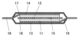
- FIG. 1 shows a cross-sectional view of an example of a lithium ion secondary battery according to this embodiment.
- a lithium ion secondary battery having a positive electrode containing a positive electrode active material, the secondary battery including a single-plate laminate type battery cell.
- the positive electrode includes a positive electrode active material 11 and a positive electrode current collector 13
- the negative electrode includes a negative electrode active material 12 and a negative electrode current collector 14.
- the positive electrode active material 11 and the negative electrode active material 12 face each other with a separator 15 interposed therebetween.
- the positive electrode current collector 13 and the negative electrode current collector 14 are generally made of a metal foil, and the positive electrode active material 11 and the negative electrode active material 12 are applied and solidified on one side of each.
- the ends of the positive electrode current collector 13 and the negative electrode current collector 14 are drawn out of the battery cell as a positive electrode tab 18 and a negative electrode tab 19, respectively, and the battery cell is sealed from above and below by exterior laminates 16 and 17. ing.
- the sealed battery cell is filled with an electrolyte solution.
- an electrolyte solution a non-aqueous organic electrolyte solution in which a lithium salt is dissolved as a supporting salt can be used.
- the lithium ion secondary battery according to the present embodiment is basically not limited in battery shape, and the electrode shape may be a wound type or a laminated type as long as the positive electrode and the negative electrode are opposed to each other with a separator interposed therebetween. It is also possible. Further, the structure of the battery cell can be not only the single plate laminate type but also a coin type, a laminate pack type, a square cell, a cylindrical cell, or the like.
- a lithium ion secondary battery includes a positive electrode including a lithium compound as a positive electrode active material, and a negative electrode including a negative electrode active material capable of occluding and releasing lithium ions. Between the positive electrode and the negative electrode, both In order to prevent electrical connection from occurring, a non-conductive separator and an electrolyte region are provided. Here, both the positive electrode and the negative electrode are held in a state immersed in an electrolyte solution having lithium ion conductivity, and these components are sealed in a container.
- lithium nickel manganese oxide which is a positive electrode active material
- the following raw materials can be used.
- Li raw material Li 2 CO 3 , LiOH, LiNO 3 , Li 2 O, Li 2 SO 4, or the like can be used. Among these, Li 2 CO 3 and LiOH are particularly preferable.
- Ni raw material NiO, Ni (OH) 2 , NiSO 4, Ni (NO 3) 2 and the like can be used.
- Mn raw material examples include various manganese oxides such as electrolytic manganese dioxide (EMD), Mn 2 O 3 , Mn 3 O 4 , and CMD (Chemical Manganese Dioxide), MnCO 3 , MnSO 4 , Mn (CH 3 COO) 2 and the like.
- EMD electrolytic manganese dioxide
- Mn 2 O 3 , Mn 3 O 4 , and CMD Chemical Manganese Dioxide
- MnCO 3 , MnSO 4 , Mn (CH 3 COO) 2 and the like can be used.
- TiO 2 or the like can be used.
- Co raw material CoO, Co 3 O 4 , CoCl 2 , Co (OH) 2 , CoSO 4 , CoCO 3 , Co (NO 3 ) 2 or the like can be used.
- Fe 2 O 3 , Fe 3 O 4 , Fe (OH) 2 , FeOOH, etc. can be used as the Fe raw material.
- Cr raw material Cr (NO 3 ) 3 , Cr 2 O 3 , Cr 2 (CO 3 ) O 3 or the like can be used.
- Al raw material Al (OH) 3 , Al (CH 3 COO) 3 or the like can be used.
- Mg raw material Mg (OH) 2 , Mg (CH 3 COO) 2 or the like can be used.
- B 2 O 3 or the like can be used as the B raw material.
- Si raw material SiO, SiO 2 or the like can be used.
- the obtained mixed powder is fired in air or oxygen at a temperature of 600 ° C. to 950 ° C. to obtain a positive electrode active material.
- the firing temperature is preferably a high temperature for diffusing each element, but if the firing temperature is too high, oxygen deficiency may occur and the battery characteristics may deteriorate. For this reason, the firing temperature is preferably 600 ° C. to 850 ° C.
- baking in an oxygen atmosphere is preferable in order to prevent generation of oxygen deficiency.
- the specific surface area of the positive electrode active material As a method of setting the specific surface area of the positive electrode active material to 0.2 m 2 g ⁇ 1 or more and 1 m 2 g ⁇ 1 or less, it can be adjusted to the above range by adjusting each of the Li amount and the firing temperature. .
- lithium titanium oxide that is a negative electrode active material
- the following raw materials can be used.
- Li raw material Li 2 CO 3 , LiOH, LiNO 3 , Li 2 O, Li 2 SO 4, or the like can be used. Among these, Li 2 CO 3 and LiOH are particularly preferable.
- Ti raw material TiO 2 or the like can be used.
- Ta 2 O 5 or the like can be used as the Ta material
- ZrO 2 or the like can be used as the Zr material
- CrO 2 can be used as the Cr material
- NiO can be used as the Ni material
- VO 2 can be used as the V material.
- the obtained mixed powder is fired in air or oxygen at a temperature of 600 ° C. to 1000 ° C. to obtain a negative electrode active material.
- the firing temperature is preferably a high temperature for diffusing each element, but if the firing temperature is too high, oxygen deficiency may occur and the battery characteristics may deteriorate. Therefore, the firing temperature is preferably 750 ° C to 900 ° C.
- baking in an oxygen atmosphere is preferable in order to prevent generation of oxygen deficiency.
- the specific surface area of the negative electrode active material As a method of setting the specific surface area of the negative electrode active material to 4 m 2 g ⁇ 1 or more and 20 m 2 g ⁇ 1 or less, it can be adjusted to the above range by adjusting each of the Li amount and the firing temperature.
- the produced powdered positive electrode active material and negative electrode active material each have a predetermined crystal structure can be evaluated by powder X-ray diffraction.
- Each powdery lithium compound is set in a powder X-ray diffractometer, and the result obtained by measuring the diffraction angle and intensity of the diffracted light obtained by irradiating characteristic X-rays is obtained as an ICDD Cards (International Center for Diffraction Data).
- the crystal structure is identified by querying Cards: powder X-ray diffraction pattern database card).
- the diffraction patterns of the obtained powdered positive electrode active material and negative electrode active material are Li x (Ni a Mn 2- abM1 b ) O 4 , Li y Ti (5-c). / 3 M2 c O 4 It is possible to identify the crystal structure and the crystallization rate of the compound formed by comparing the diffraction pattern with each crystal structure and measuring the diffraction intensity.
- the obtained positive electrode active material, conductivity imparting agent, binder and solvent are mixed and applied on the surface of the positive electrode current collector to form a film.
- the conductivity-imparting agent include carbon materials such as acetylene black, carbon black, graphite, and fibrous carbon, metal substances such as Al, and conductive oxide powders. These may use only 1 type and may use 2 or more types together.
- the binder in addition to polyvinylidene fluoride (PVDF), fluorine rubber or the like can be used.
- the fluororubber examples include vinylidene fluoride-hexafluoropropylene (VDF-HFP) copolymer, vinylidene fluoride-hexafluoropropylene-tetrafluoroethylene (VDF-HFP-TFE) copolymer, Vinylidene fluoride-pentafluoropropylene (VDF-PFP) copolymer, vinylidene fluoride-pentafluoropropylene-tetrafluoroethylene (VDF-PFP-TFE) copolymer, vinylidene fluoride-perfluoromethyl vinyl ether-tetra Examples thereof include a fluoroethylene (VDF-PFMVE-TFE) copolymer, an ethylene-tetrafluoroethylene copolymer, and a propylene-tetrafluoroethylene copolymer.
- VDF-HFP vinylidene fluoride-hexafluoropropylene
- a fluorine-containing polymer in which hydrogen in the main chain is substituted with an alkyl group can also be used. These may use only 1 type and may use 2 or more types together.
- a metal thin film mainly composed of aluminum, an aluminum alloy, titanium, or the like can be used.
- the preferable addition amount of the conductivity-imparting agent is 0.5 to 30% by mass with respect to the total amount of the positive electrode active material excluding the solvent, the conductivity-imparting agent and the binder.
- a preferable addition amount of the binder is similarly 1 to 10% by mass with respect to the total amount.
- a preferable content ratio of the positive electrode active material is 70% by mass or more and 98.5% by mass or less, and more preferably 85% by mass or more and 97% by mass or less with respect to the total amount.
- the density of the positive electrode active material in the positive electrode active material layer formed by applying the positive electrode active material to the surface of the positive electrode current collector is preferably 1 g / cm 3 or more and 4.5 g / cm 3 or less. More preferably, it is 2 g / cm 3 or more and 4 g / cm 3 or less.
- the density of the positive electrode active material layer exceeds 4.5 g / cm 3 , since there are few voids in the positive electrode active material layer, an electrolyte solution that fills the periphery of the positive electrode of the lithium ion secondary battery becomes a void in the positive electrode. It may be difficult to enter. For this reason, the amount of movement of Li ions is reduced, and the charge / discharge rate characteristics of the battery may be reduced.
- the density of the positive electrode active material layer is less than 1 g / cm 3 , the energy density of the lithium ion secondary battery to be produced is the same as when the content ratio of the positive electrode active material in the positive electrode active material layer is small. May decrease.
- the obtained negative electrode active material, a conductivity imparting agent, a binder, and a solvent are mixed and applied onto the surface of the negative electrode current collector to form a film.
- a conductivity-imparting agent the same conductivity-imparting agent as that used in the production of the positive electrode can be used.
- the binder in addition to polyvinylidene fluoride (PVDF), tetrafluoroethylene, polyvinylidene fluoride, polyethylene, polypropylene, ethylene-propylene diene terpolymer (EPDM), sulfonated EPDM, styrene butadiene rubber (SBR), the fluorine A thermoplastic resin such as rubber or carbomethoxycellulose, a polymer having rubber elasticity, or the like can be used. These may use only 1 type and may use 2 or more types together.
- the negative electrode current collector a metal thin film mainly composed of copper, nickel, or the like can be used.
- the preferable addition amount of the negative electrode active material, the conductivity imparting agent, and the binder is the same as the preferable addition amount of the positive electrode active material, the conductivity imparting agent, and the binder in the positive electrode preparation.
- the density of the negative electrode active material in the negative electrode active material layer formed by applying the negative electrode active material to the surface of the current collector is preferably 2 g / cm 3 or more and 2.5 g / cm 3 or less. The reason why this range is preferable is the same as the density of the positive electrode active material.
- an aprotic organic solvent for the electrolyte solution according to the lithium ion secondary battery in the present embodiment.
- the aprotic organic solvent include ethylene carbonate (EC), propylene carbonate (PC), butylene carbonate (BC), cyclic carbonates such as vinylene carbonate (VC), dimethyl carbonate (DMC), ethyl methyl carbonate (EMC), Linear carbonates such as diethyl carbonate (DEC) and dipropyl carbonate (DPC), aliphatic carboxylic acid esters such as methyl formate, methyl acetate and ethyl propionate, ⁇ -lactones such as ⁇ -butyrolactone, 1, 2 -Chain ethers such as diethoxyethane (DEE) and ethoxymethoxyethane (EME), cyclic ethers such as tetrahydrofuran and 2-methyltetrahydrofuran, dimethyl sulfoxide, 1,3-d
- a polymer or the like added to the aprotic organic solvent to solidify the electrolyte solution into a gel may be used.
- a room temperature molten salt or an ionic liquid represented by a cyclic ammonium cation or the same anion may be used.
- a method in which a cyclic carbonate and a chain carbonate are mixed and used is particularly preferable from the viewpoints of conductivity and stability under a high voltage.
- lithium salt as a supporting salt.
- the lithium salt LiPF 6, LiAsF 6, LiAlCl 4, LiClO 4, LiBF 4, LiSbF 6, LiBOB (Lithium bis (oxalate) borate), LiCF 3 SO 3, LiC 4 F 9 SO 3, LiC (CF 3 SO 2) 3, LiN (CF 3 SO 2) 2, LiN (C 2 F 5 SO 2) 2, LiCH 3 SO 3, LiC 2 H 5 SO 3, LiC 3 H 7 SO 3, lithium lower aliphatic carboxylic acids and Other lithium carboxylates, lithium chloroborane, lithium tetraphenylborate, LiBr, LiI, LiSCN, LiCl, LiF and the like can be mentioned.
- the electrolyte concentration of the dissolved support salt is preferably 0.5 mol / l or more and 1.5 mol / l or less. If the electrolyte concentration of the supporting salt is higher than 1.5 mol / l, the density and viscosity of the electrolyte solution may increase and Li ion migration may be hindered. Conversely, if the electrolyte concentration is lower than 0.5 mol / l, the electrical conductivity of the electrolyte solution may be reduced.
- the separator used in the lithium ion secondary battery of this embodiment is preferably a polymer film such as a propylene film.
- the lithium ion secondary battery according to this embodiment can be manufactured, for example, by the following method.
- a positive electrode active material and a negative electrode active material are respectively formed on the surfaces of the positive electrode current collector and the negative electrode current collector to form a positive electrode and a negative electrode, and a separator is sandwiched between them to form an electrode body.
- an electrolyte solution in a film structure or the like formed by laminating a synthetic resin and a metal foil in dry air or an inert gas atmosphere lithium ions having a single plate laminate type cell A secondary battery can be manufactured.
- the electrode body is further rolled to form a wound body, which is also housed in a battery can in a dry air or inert gas atmosphere, filled with an electrolyte solution, and sealed to form a cylindrical or square cell.
- a lithium ion secondary battery having a shape can be manufactured.
- the potential of the positive electrode of the lithium ion secondary battery produced here is preferably 5.5 V or less with respect to the potential of Li.
- a lithium ion secondary battery has a property that the decomposition of the electrolyte solution proceeds when the positive electrode potential is high, and particularly in order to maintain the reliability of the battery when repeatedly charging and discharging at a high temperature of 60 ° C. or higher. More preferably, the potential of the positive electrode is 5.3 V or less.
- the potential of the negative electrode is preferably 1 V or more with respect to the potential of Li.
- Lithium ion secondary batteries in which the specific surface areas and compositions of the positive electrode active material and the negative electrode active material were changed were produced, and each was used as an example and a comparative example. All of these lithium ion secondary batteries have single-plate laminated cells having the same shape. These lithium ion secondary batteries were held at a high temperature and evaluated for a reduction in discharge capacity. Hereafter, the preparation methods and evaluation methods of the lithium ion secondary battery of an Example and a comparative example are demonstrated.
- Li 2 CO 3 was used as a Li raw material. NiO, MnO 2 , TiO 2 , SiO 2 , CoO, Fe 2 O 3 , Cr 2 O 3 , Al 2 O 3 , MgO, and B 2 O 3 were used as raw materials other than Li.
- the raw materials of Li 2 CO 3 , NiO, MnO 2 , and M1 were weighed so as to have the desired composition ratios, and pulverized and mixed.
- the powder after mixing the raw materials was fired at a temperature range of 750 to 950 ° C. for 9 hours. Then, coarse particles were removed from the mixture through a 30 ⁇ m mesh sieve to obtain a positive electrode active material powder.
- the positive electrode active material had a substantially single-phase spinel structure.
- the specific surface area of the positive electrode active material was measured using a gas adsorption amount measuring device “QS-18” (trade name, manufactured by Quanta Chrome). The method for measuring the specific surface area is the same for the negative electrode active material described later.
- the positive electrode active material powder obtained in the above step and the conductivity-imparting material were dispersed in a solution obtained by dissolving a binder in an organic solvent and kneaded to form a slurry.
- Carbon black which is a carbon material, was used as the conductivity imparting material.
- Polyvinylidene fluoride (PVDF) was used as a binder.
- N-methyl-2-pyrrolidone (NMP) was used as the organic solvent.
- the mass ratio of the positive electrode active material, the conductivity imparting material, and the binder was 90: 6: 4.
- the prepared slurry was applied onto a positive electrode current collector made of an aluminum (Al) foil having a thickness of 20 ⁇ m to form a positive electrode active material layer, thereby obtaining a laminate.
- the initial charge capacity per unit area of the positive electrode to be manufactured (the amount of charge accumulated in the battery when the fully charged non-charged battery is first fully charged) is 2.0 mAh / cm 2.
- the thickness of the positive electrode active material layer to be applied was adjusted.
- the produced laminate was dried and solidified in a vacuum for 12 hours to obtain a positive electrode material.
- This positive electrode material was cut into a square 20 mm long and 20 mm wide. Then, it pressure-molded with the pressure of 3 t / cm ⁇ 2 >, and produced the positive electrode.
- LiOH was used as a Li raw material.
- raw materials other than Li TiO 2 , Ta 2 O 5 , ZrO 2 , CrO 2 , NiO, and VO 2 were used.
- the raw materials of LiOH, TiO 2 and M2 were weighed so as to have the desired composition ratios, and pulverized and mixed.
- the powder after mixing the raw materials was fired at a temperature range of 700 to 1000 ° C. for 12 hours. Then, coarse particles were removed from the mixture through a 2 ⁇ m mesh sieve to obtain a powder of a negative electrode active material.
- the same powder X-ray diffraction as described above was confirmed to have a substantially single-phase spinel structure.
- the negative electrode active material powder obtained in the above step and the conductivity-imparting material were dispersed in a solution obtained by dissolving a binder in an organic solvent and kneaded to form a slurry.
- Carbon black which is a carbon material, was used as the conductivity imparting material.
- Polyvinylidene fluoride (PVDF) was used as a binder.
- NMP N-methyl-2-pyrrolidone
- the prepared slurry was applied on a negative electrode current collector made of a copper (Cu) foil having a thickness of 10 ⁇ m to form a negative electrode active material layer, thereby obtaining a laminate.
- the thickness of the negative electrode active material layer to be applied was adjusted so that the initial charge capacity per unit area of the negative electrode to be manufactured was 2.6 mAh / cm 2 .
- the produced laminate was dried and solidified in a vacuum for 12 hours to obtain a negative electrode material.
- This negative electrode material was cut into a square of 22 mm length and 22 mm width. Then, it pressure-molded with the pressure of 1 t / cm ⁇ 2 >, and produced the negative electrode.
- the positive electrode and the negative electrode produced by the above method were arranged so that the active material layers of the positive electrode and the negative electrode face each other, and were placed in a battery cell as a laminate cell with a separator interposed therebetween.
- a polypropylene film as an insulator was used as the separator, and the shape of the separator was larger than that of either the positive electrode or the negative electrode. For this reason, the positive electrode and the negative electrode are insulated from each other by the separator.
- an Al tab which is a lead leading out of the battery, is joined to the end of the positive electrode current collector, and a nickel (Ni) tab of the lead lead is similarly joined to the end of the negative electrode current collector.
- lithium ion secondary battery having a single-plate laminate type battery cell was assembled.
- 10 lithium ion secondary batteries each having a positive electrode active material having the same composition were produced by a series of these assembly steps.
- the following evaluation was implemented with respect to the lithium ion secondary battery produced by the said process.
- the prepared lithium ion secondary battery was charged by a constant current and constant voltage method with an upper limit voltage of 3.4 V and a current value of 1.6 mA, and was fully charged (initial charge).
- the discharge was performed at a constant current with the lower limit voltage being 1.5 V (initial discharge).
- the discharge capacity at this time (the amount of charge taken out from the battery by the initial discharge) is defined as the initial discharge capacity.
- the battery was charged again under the same charging conditions as the initial charge to obtain a fully charged state, and the battery was kept at 60 ° C. and stored for 90 days.
- the upper limit voltage is set to 3.4 V and the current density is 50 times that of the initial charge.
- a rapid charge for 15 minutes was performed by a constant current constant voltage method at a current value of 80 mA.
- discharging was performed again at a constant current of 1.6 mA to a lower limit voltage of 1.5 V, and the discharge capacity at that time was measured. This is defined as the discharge capacity after holding.
- the ratio of the discharge capacity value after holding to the initial discharge capacity in each battery is measured and the specific surface area and composition of the positive electrode active material and the negative electrode active material are changed, how the ratio value of the discharge capacity changes Each was evaluated.
- the initial charge capacity of each battery is set to a constant value of 2.0 mAh / cm 2 , and the size of the positive electrode that captures and releases Li ions is the same for each battery. It is 20 mm long and 20 mm wide. Therefore, the initial charge capacity of each battery is the same at 8 mAh. Therefore, if each battery is charged at a constant current of 8 mA, it can be almost fully charged in one hour.
- charging at a constant current of 8 mA is referred to as 1C.
- the upper limit voltage is set at the time of charging, the actual charging of each battery is constant current constant voltage charging that shifts to constant voltage charging when the charging voltage reaches the upper limit voltage.
- charging is initially performed at a constant current of 80 mA, and when the upper limit voltage is reached, the charging is switched to constant voltage charging.
- the fast charge for 15 minutes at the current value of 80 mA after the discharge after storage at 60 ° C. for 90 days in the evaluation of the lithium ion secondary battery is this constant current / constant voltage charge at 10 C15.
- a lithium ion secondary battery in which the specific surface area and composition of the positive electrode active material and the negative electrode active material were changed under the above production conditions was produced as Examples and Comparative Examples.
- the ratio (hereinafter, capacity retention rate) was evaluated.
- the evaluation results are shown in Tables 1 to 7, respectively.
- the composition of each lithium compound in the positive electrode active material constituting each lithium ion secondary battery, the capacity retention rate value (unit%) in each composition, and the determination (A and B) are shown. Show.
- the lithium ion secondary battery evaluated for every composition is 10 pieces each, and the value of the capacity maintenance rate in the battery of each composition is an average value of the measured value in these 10 batteries.
- the evaluation method of the capacity maintenance rate before and after holding at high temperature in this example is equivalent to JIS C8711 for the evaluation standard for determining the case where it is 50% or more, but it depends on the severity of the actual test contents. , Substantially exceeding the standards of JIS C8711.
- the reason why the battery evaluation method in this example was made to be a stricter standard compared with the general method defined in the Japanese Industrial Standard is that lithium ions mounted on portable electronic devices in recent years. This is because the secondary battery demands a product that satisfies a stricter level than ever before in terms of maintaining the charging capacity during long-term use.
- a lithium ion secondary battery that satisfies the evaluation criteria employed in this example has more excellent characteristics with respect to capacity retention during long-term storage.
- the configuration of the positive electrode active material and the negative electrode active material is specifically specified, and thereby excellent characteristics are obtained.
- Example 1 The positive electrode active material and the negative electrode active material composing the lithium ion secondary battery were fixed, and batteries were prepared by changing the specific surface area of each lithium compound. Examples 1 to 11 and Comparative Examples 1 to 7 were respectively used. It was. Table 1 shows the evaluation results of the capacity retention rates.
- the compositions of the positive electrode active material and the negative electrode active material are LiNi 0.5 Mn 1.5 O 4 and Li 4/3 Ti 5/3 O 4 , respectively.
- a predetermined specific surface area was obtained by appropriately adjusting the firing temperature during the production of the positive electrode active material and the negative electrode active material.
- the conditions for the capacity retention rate to be 50% or more are that the specific surface area of the positive electrode active material is 0.2 m 2 g ⁇ 1 or more, 1 m 2 g ⁇ 1 or less, the negative electrode In this case, the specific surface area of the active material satisfies the range of 4 m 2 g ⁇ 1 or more and 20 m 2 g ⁇ 1 or less.
- Example 12 to 15 Comparative Examples 8 to 11
- the composition of the negative electrode active material was Li 4/3 Ti 5/3 O 4 and the specific surface area was 5 m 2 g ⁇ 1 .
- Batteries in which the specific surface area of the positive electrode active material was fixed to 0.5 m 2 g ⁇ 1 and only the amount of Ni in the positive electrode active material was changed were prepared, and were designated as Examples 12 to 15 and Comparative Examples 8 to 11, respectively.
- Table 2 shows the evaluation results of the capacity retention rates.
- Table 6 shows Example 6 described above.
- Example 16 to 27, Comparative Examples 12 to 15 The composition of the negative electrode active material was Li 4/3 Ti 5/3 O 4 and the specific surface area was 10 m 2 g ⁇ 1 . Batteries were prepared by fixing the specific surface area of the positive electrode active material to 0.5 m 2 g ⁇ 1 and changing only the amount of M1 of the positive electrode active material, and were designated as Examples 16 to 27 and Comparative Examples 12 to 15, respectively. Table 3 shows the evaluation results of the capacity retention rates. For comparison, Table 9 shows Example 9 described above.
- Example 28 to 32 Comparative Example 16
- the composition of the negative electrode active material was Li 4/3 Ti 5/3 O 4 and the specific surface area was 20 m 2 g ⁇ 1 .
- Batteries in which the specific surface area of the positive electrode active material was fixed at 0.5 m 2 g ⁇ 1 , the amount of M1 was fixed at 0.1, and only M1 was changed were produced, which were designated as Examples 28 to 32 and Comparative Example 16, respectively.
- Table 4 shows the evaluation results of the capacity retention rates.
- Example 33 to 40 The composition of the negative electrode active material was Li 4/3 Ti 5/3 O 4 and the specific surface area was 20 m 2 g ⁇ 1 .
- Examples 33 to 40 were produced by preparing batteries in which the specific surface area of the positive electrode active material was fixed at 0.5 m 2 g ⁇ 1 , M1 was 2 or more, and the compositions were changed. Table 5 shows the evaluation results of the capacity retention rates.
- Example 41 to 45 Comparative Examples 17 and 18
- the composition of the positive electrode active material was LiNi 0.45 Li 0.05 Mn 1.4 Ti 0.1 O 4 and the specific surface area was 0.5 m 2 g ⁇ 1 .
- Batteries were prepared by fixing the specific surface area of the negative electrode active material to 20 m 2 g ⁇ 1 and changing only c in the formula (II), which was the amount of M2 and M2 of the negative electrode active material. Examples 17 and 18 were designated. Table 6 shows the evaluation results of the capacity retention rates.
- Example 46 to 48 Comparative Example 19
- the composition of the positive electrode active material was LiNi 0.4 Li 0.05 Al 0.05 Mn 1.4 Si 0.1 O 4 and the specific surface area was 0.5 m 2 g ⁇ 1 .
- Batteries were prepared by fixing the specific surface area of the negative electrode active material to 20 m 2 g ⁇ 1 and changing only c in the formula (II), which was the amount of M2 and M2 of the negative electrode active material.
- Example 19 was adopted. Table 7 shows the evaluation results of the capacity retention rates.
- the lithium ion secondary battery according to the present embodiment can maintain sufficient rapid charging characteristics even after long-term use by the user. Therefore, according to the present embodiment, it is possible to provide a lithium ion secondary battery having high reliability that is actually used by a user. That is, according to this embodiment, it was found that a lithium ion secondary battery capable of rapid charging can be provided.
Landscapes
- Chemical & Material Sciences (AREA)
- Chemical Kinetics & Catalysis (AREA)
- Electrochemistry (AREA)
- General Chemical & Material Sciences (AREA)
- Inorganic Chemistry (AREA)
- Engineering & Computer Science (AREA)
- Materials Engineering (AREA)
- Manufacturing & Machinery (AREA)
- Battery Electrode And Active Subsutance (AREA)
- Secondary Cells (AREA)
Abstract
急速充電での電池の容量低下が小さく、高エネルギー密度のリチウムイオン二次電池を提供する。正極が式(I) LixNiaM1bMn2-a-bO4 (I) (式(I)において、M1はTi、Si、Co、Fe、Cr、Al、Mg、B及びLiからなる群から選択される少なくとも一種を示す。0<x≦1、0.4≦a≦0.6、0≦b≦0.4である。)で表され、比表面積が0.2~1m2g-1であるリチウムニッケルマンガン酸化物を含み、負極が式(II) LiyTi5/3-cM2cO4 (II) (式(II)において、M2はTa、Zr、Cr、Ni及びVからなる群から選択される少なくとも一種を示す。4/3≦y≦7/3、0≦c<0.1である。)で表され、比表面積が4~20m2g-1であるリチウムチタン酸化物を含むリチウムイオン二次電池。
Description
本実施形態はリチウムイオン二次電池に関するものである。さらに詳しくは、エネルギー密度が高く、急速充電特性の優れたリチウムイオン二次電池に関するものである。
モバイル機器に対する技術開発と需要が増大するに伴い、エネルギー源としての二次電池に対する需要が急増している。最近では、電気自動車(EV)、ハイブリッド電気自動車(HEV)等における動力源としてリチウムイオン二次電池の使用が現実化するに至った。近年では様々な要求に応えうるリチウムイオン二次電池への多くの研究が行われており、特に、安価で高エネルギー密度であり、かつ急速充電特性を有するリチウムイオン二次電池の開発が急がれている。
リチウムイオン二次電池は、正極と負極とがセパレータを介して対峙した構成を有する。正極と負極とはそれぞれ正極集電体と正極活物質、負極集電体と負極活物質から構成されている。これらの各素子には非水性の電解質溶液が含浸されている。このリチウムイオン二次電池に充電もしくは放電を行うと、電解質溶液に溶解したリチウムイオンがセパレータを通過して正極と負極との間を移動し、正極活物質と負極活物質とにおいてそれぞれリチウムイオンの吸蔵、放出が行われる。これによって電池として動作する。
リチウムイオン二次電池に用いられる負極活物質としては、炭素材料のようにリチウムイオンを吸蔵、放出する材料や、リチウム(Li)と合金を形成するアルミニウム(Al)、シリコン(Si)、スズ(Sn)等の金属材料が用いられている。
しかしながら、炭素材料やLiと合金を形成するAl、Si、Sn等の金属材料は、初回充放電時に不可逆反応が生じる。また、その還元電位がLi/Li+に対して約0.1V付近と低く、負極表面上において非水電解液の還元分解を引き起こし易い。この現象に起因した寿命特性低下も問題となっている。
そこで、近年、負極材料をチタン酸リチウム(Li4/3Ti5/3O4)で置き換えることが提案されている。Li4/3Ti5/3O4は、還元電位がLi/Li+に対して約1.5Vと高く、負極表面における非水電解液の還元分解を抑制できることに加え、スピネル構造に起因する結晶構造の安定さから、負極及び非水電解液に起因する急速充電特性の低下も抑制できるため実用化に供されるようになった。しかしながら、Li4/3Ti5/3O4の動作電位が、Li/Li+に対して約1.5Vと高いため、グラファイト(動作電圧:0~0.5V vs.Li/Li+)と比較すると電池電圧が低下し、エネルギー密度が低下する課題があった。
一方、リチウムイオン二次電池に用いられる正極活物質としては、作動電圧が4Vをこえることからコバルト酸リチウム(LiCoO2)の研究が精力的に行われ、小型携帯機器用途ではLiCoO2の採用が主流である。このLiCoO2は、電位平坦性、容量、放電電位、サイクル特性等総合的な性能で良好な特性を示すため、今日のリチウムイオン二次電池の正極活物質として広く用いられている。
しかしながら、Coは地球上に偏在し、かつ希少な資源であるために、コストが高くつくため、自動車用電池を睨んだ将来の量産化、大型化に対応し難い。またLiCoO2は層状岩塩構造(α-NaFeO2構造)を有しているため、充電時のリチウム離脱により、電気陰性度の大きな酸素層が隣接することになる。そのため、実使用時にはリチウムの引き抜き量を制限する必要があり、過充電状態等リチウムの引き抜き量が多すぎる場合、酸素層間の静電反発力による構造変化を起こして発熱するため、電池の安全性に改善の余地がある。電池の安全性を確保するために外部に大きな保護回路を必要とするため、エネルギー密度が低下してしまう。そのため、安全性の高い正極材料が求められている。
そこで、Coに代わる資源として、地球上に豊富に存在し、しかも安価なNiやMnやFeをベースにした正極活物質、例えば、鉄燐酸リチウム(LiFePO4)、ニッケル酸リチウム(LiNiO2)、マンガン酸リチウム(LiMn2O4)等を基本構成とするリチウム含有遷移金属酸化物を用いた正極材料が提案され、実用に供されるようになった。
LiFePO4は、オリビン型構造を有し、酸素が鉄以外の元素と共有結合することで固定化されているため、高温においても酸素を放出することが無く、LiCoO2、LiNiO2、LiMn2O4等の正極活物質と比較すると電池の安全性を高めることができると推察される。しかしながら、LiFePO4の電気伝導率は10-9S/cm程度とLiMn2O4やLiNiO2の電気伝導率10-5S/cmと比べて著しく低く急速充電特性が低いという問題も指摘されている。さらに、動作電圧もLi/Li+に対して約3.3Vと低いという問題も指摘されている。
LiNiO2は、単位重量当たりの理論容量が274mAhg-1と大きく、電池活物質として魅力的であり、電気自動車の電源への実用化に最も期待されている材料である。しかし、LiNiO2はLiCoO2同様に層状岩塩構造(α-NaFeO2構造)を有しているため、充電時のリチウム離脱により、電気陰性度の大きな酸素層が隣接することになる。そのため、実使用時にはリチウムの引き抜き量を制限する必要があり、過充電状態などリチウムの引き抜き量が多すぎる場合、酸素層間の静電反発力による構造変化を起こして発熱するため、電池の安全性に大きな改善の余地がある。電池の安全性を確保するために外部に大きな保護回路を必要とするため、エネルギー密度が低下してしまう。
LiMn2O4は、正スピネル型構造を有し、かつ空間群Fd3mを有することから、リチウム電極に対し4V級というLiCoO2と同等の高い電位を有し、合成が容易、高い電池容量を有する等の優れた特徴を有するために、非常に有望な材料として注目され、実用化もされてきた。しかしLiMn2O4は、このように優れた材料であるが、高温保存時における容量劣化が大きくMnが電解液に溶解してしまい、急速充電特性が十分でないという問題がある。これは3価Mnの不安定性に起因するものであり、Mnイオンの平均価数が3価と4価の間で変化する際に、Jahn-Teller(ヤーン・テラー)歪みが結晶中に生じ、結晶構造の安定性が低下することにより伴う性能劣化等が発生すると考えられている。
こうしたことから、これまで電池の信頼性を高めることを目的として、3価のMnを他元素で置換し構造安定性を向上させる検討が行われてきた。例えば特許文献1には、こうした正極活物質を備えた二次電池が開示されており、LiMn2O4に含まれる3価Mnを他の金属で置換した正極活物質が開示されている。すなわち、特許文献1には、スピネル構造を有し組成式LiMxMn2-xO4(MはAl、B、Cr、Co、Ni、Ti、Fe、Mg、Ba、Zn、Ge、Nbから選ばれる1種以上、0.01≦x≦1)で表されるリチウムマンガン複合酸化物を備える二次電池が記載されている。また、LiMn1.75Al0.25O4を正極活物質として用いる例が具体的に開示されている。
ところが、上記のように3価Mnを他元素で置換して減らした場合、放電容量の低下が問題となる。LiMn2O4は充放電に伴い次のようなMnの価数変化を起こす。
Li+Mn3+Mn4+O2-
4→Li++Mn4+
2O2-
4+e-
前記式からわかるように、LiMn2O4は3価のMnと4価のMnが含まれており、このうちの3価のMnが4価に変化することで放電が起こる。したがって、3価のMnを他元素に置換すれば、必然的に放電容量の低下をもたらすことになる。すなわち、正極活物質の構造安定性を高めて電池の信頼性を向上させようとしても、放電容量の低下が顕著となり、両者を両立させることは困難である。特に、放電容量値130mAh/g以上で信頼性の高い正極活物質を得ることは非常に困難である。
前記式からわかるように、LiMn2O4は3価のMnと4価のMnが含まれており、このうちの3価のMnが4価に変化することで放電が起こる。したがって、3価のMnを他元素に置換すれば、必然的に放電容量の低下をもたらすことになる。すなわち、正極活物質の構造安定性を高めて電池の信頼性を向上させようとしても、放電容量の低下が顕著となり、両者を両立させることは困難である。特に、放電容量値130mAh/g以上で信頼性の高い正極活物質を得ることは非常に困難である。
上記のようにLiMn2O4に含まれる3価Mnを他の金属で置換した正極活物質は、いわゆる4V級の起電力を有するリチウム二次電池を構成する。これとは別の方向の技術として、例えば、特許文献2などには、LiMn2O4のMnの一部をNi、Co、Fe、Cu、Cr等で置換し、充放電電位を高くして、エネルギー密度を増加させる検討がなされている。これらはいわゆる5V級の起電力を有するリチウム二次電池を構成する。以下、LiNi0.5Mn1.5O4を例に挙げて説明する。LiNi0.5Mn1.5O4は充放電に伴い次のようなNiの価数変化を起こす。
Li+Ni2+
0.5Mn4+
1.5O2-
4→Li++Ni4+
0.5Mn4+
1.5O2-
4+e-
前記式からわかるように、LiNi0.5Mn1.5O4は2価のNiが4価に変化することで放電が起こる。Mnについては価数変化はない。このように、充放電に関与する金属をMnからNi、Co等に代えることで、4.5V以上の高い起電力を得ることができる。
前記式からわかるように、LiNi0.5Mn1.5O4は2価のNiが4価に変化することで放電が起こる。Mnについては価数変化はない。このように、充放電に関与する金属をMnからNi、Co等に代えることで、4.5V以上の高い起電力を得ることができる。
また、特許文献2には、正極活物質として、Li金属に対して4.5V以上の電位で充放電を行うスピネル構造の結晶LiMn2-y-zNiyMzO4(但し、M:Fe、Co、Ti、V、Mg、Zn、Ga、Nb、Mo、Cuよりなる群から選ばれた少なくとも一種、0.25≦y≦0.6、0≦z≦0.1)が開示されている。特許文献4には、LiMn2O4のMnを他遷移金属で置換し、さらに、他元素で置換した一般式LiaMn2-y-i-j-kMyM1iM2jM3kO4(但し、M1:2価カチオン、M2:3価カチオン、M3:4価カチオン、M:Mnを除く少なくとも1種の遷移金属元素、i≧0、j≧0、k≧0、i+j>0)で表される5V級正極活物質が開示されている。
特許文献3には、リチウム二次電池の負極活物質にLixTi5/3-yLyO4(Lは1種以上の遷移金属で、Ti以外の元素、4/3≦x≦7/3、0≦y≦5/3))を、正極活物質にLim〔Ni2-nMnO4〕〕(Mは1種以上の遷移金属で、Ni以外の元素、1≦m≦2.1、0.75≦n≦1.80)を用いることにより、エネルギー密度が高く、自己放電が少ない保存特性が改善されることが開示されている。特許文献4には、リチウム二次電池の負極活物質にLi4Ti5O12を、正極活物質にLiNi0.5Mn1.5O4を用いることにより、高温サイクルが改善されることが開示されている。
しかしながら、前記正極活物質、負極活物質を用いて作製したリチウムイオン二次電池は、急速充放電特性が十分ではなく、更なる改善が必要である。
リチウムイオン二次電池をEV、HEV等の駆動電源として用いる場合には、ユーザ側の要請として、充電時間を短縮する、即ち急速充電を可能とすることが求められている。一般的なリチウムイオン二次電池は、1時間~3時間で満充電となるような充電条件で使用されているが、この充電時間を例えば10分ないし15分程度にまで短縮することができれば、リチウムイオン二次電池の利便性を大幅に高めることができる。しかし前記リチウムイオン二次電池にこのような急速充電を実施すると、僅かな使用期間でリチウムイオン二次電池の特性の大幅な劣化を招くことが知られている。この電池の特性の劣化は、具体的には短い経年での充電可能な電池の放電容量(もしくはエネルギー密度)の大幅な非可逆的な低下として表れる。即ち、リチウムイオン二次電池の充電時間の短縮とその電池の容量の低下とは、トレードオフの関係にあることが知られている。なお電池の放電容量の低下の割合は、一般に容量維持率の低下として表される。
一般にリチウムイオン二次電池の急速充電特性を向上させ、短時間での充電を可能にするためには、正極活物質としてスピネル構造を有するLiMn2O4あるいはLiNi0.5Mn1.5O4を、負極活物質としてスピネル構造を有するLi4/3Ti5/3O4を使用することが好適であることが知られている。しかしながら、LiMn2O4を正極活物質として用いた場合は、充放電前後でヤーンテラーイオンであるMn3+(マンガンイオン)の価数が3価と4価の間で変化する。LiMn2O4には、ヤーンテラーイオンであるMn3+と非ヤーンテラーイオンであるMn4+が1:1で共存しており、大きなストレスの内在した結晶格子を有している。そのためヤーンテラー歪みと称される結晶歪みが結晶中に生じてしまう。この結晶歪みにより、正極活物質の構造の不安定化が生じる可能性がある。このため、寿命面に課題があった。
さらに、正極活物質にLiMn2O4、負極活物質にLi4/3Ti5/3O4を用いた場合には、Li4/3Ti5/3O4の動作電圧が約1.5Vと高いため負極にグラファイトや合金を用いた場合と比較すると電池のエネルギー密度が低下する。
LiNi0.5Mn1.5O4を正極活物質として用いた場合は、LiNi0.5Mn1.5O4の動作電位がLiに対して約4.7V程度と高いため負極にLi4/3Ti5/3O4を用いた場合であっても高いエネルギー密度を有する電池を作製することができる。また、Li4/3Ti5/3O4は、還元電位がLi/Li+に対して約1.5Vと高く、負極表面における非水電解液の還元分解を抑制することができる。さらに、LiNi0.5Mn1.5O4は充放電前後で非ヤーンテラーイオンであるNi2+(ニッケルイオン)の価数が2価と4価の間で変化するため結晶構造の不安定化という問題は生じ得ない。
しかしながら、電池内の電解質溶液中に僅かに水分が存在する場合は、この水と電解質溶液の成分である支持塩とが反応し、Hイオン(水素イオン:H+)が生成する。支持塩としてLiPF6を用いた場合には、以下の化学式の反応が生じることが知られている。
LiPF6+H2O→POF3+Li++3F-+2H+
こうして電解質溶液中にH+が生成すると、長期使用時において、正極活物質のLiNi0.5Mn1.5O4のMnあるいはNiが、イオン化して電解質溶液中に溶解し、リチウムイオン二次電池に内部インピーダンスの非可逆な増加をもたらす問題がある。
こうして電解質溶液中にH+が生成すると、長期使用時において、正極活物質のLiNi0.5Mn1.5O4のMnあるいはNiが、イオン化して電解質溶液中に溶解し、リチウムイオン二次電池に内部インピーダンスの非可逆な増加をもたらす問題がある。
さらに、負極のLi4/3Ti5/3O4は、電気伝導度が低く、Liイオンの拡散定数が小さいため、急速充電特性には更なる改善が必要である。
本実施形態は、リチウムイオン二次電池における前記課題を解決するものであり、長時間の使用によっても急速充電時の内部インピーダンスが大きく増加しないため、急速充電での電池の容量低下の程度が小さい、即ち使用時の容量維持率の低下が小さく、高エネルギー密度のリチウムイオン二次電池を提供することを目的とする。
本実施形態に係るリチウムイオン二次電池は、正極と、負極と、を備えるリチウムイオン二次電池であって、
前記正極が、下記式(I)
LixNiaM1bMn2-a-bO4 (I)
(前記式(I)において、M1はTi、Si、Co、Fe、Cr、Al、Mg、B及びLiからなる群から選択される少なくとも一種を示す。0<x≦1、0.4≦a≦0.6、0≦b≦0.4である。)
で表され、比表面積が0.2m2g-1以上、1m2g-1以下であるリチウムニッケルマンガン酸化物を含み、
前記負極が、下記式(II)
LiyTi5/3-cM2cO4 (II)
(前記式(II)において、M2はTa、Zr、Cr、Ni及びVからなる群から選択される少なくとも一種を示す。4/3≦y≦7/3、0≦c<0.1である。)
で表され、比表面積が4m2g-1以上、20m2g-1以下であるリチウムチタン酸化物を含む。
本実施形態によれば、長時間の使用によっても急速充電時の内部インピーダンスが大きく増加しないため、急速充電での電池の容量低下の程度が小さい、即ち使用時の容量維持率の低下が小さく、高エネルギー密度のリチウムイオン二次電池を提供することができる。更に、本実施形態に係る正極活物質、負極活物質は、熱的安定性が高いため、電池が満充電の状態で高温の条件に保持された場合でも、依然として内部インピーダンスを低い値に保持することができる。したがって、本実施形態に係るリチウムイオン二次電池は、電池内部が高温となるような条件に置かれても、同様に急速充電が可能な特性を維持し続けることができる。
本実施形態に係るリチウムイオン二次電池について説明する。本実施形態に係るリチウムイオン二次電池は、正極と、負極と、を備えるリチウムイオン二次電池であって、前記正極が、下記式(I)
LixNiaM1bMn2-a-bO4 (I)
(前記式(I)において、M1はTi、Si、Co、Fe、Cr、Al、Mg、B及びLiからなる群から選択される少なくとも一種を示す。0<x≦1、0.4≦a≦0.6、0≦b≦0.4である。)で表され、比表面積が0.2m2g-1以上、1m2g-1以下であるリチウムニッケルマンガン酸化物を含み、前記負極が、下記式(II)
LiyTi5/3-cM2cO4 (II)
(前記式(II)において、M2はTa、Zr、Cr、Ni及びVからなる群から選択される少なくとも一種を示す。4/3≦y≦7/3、0≦c<0.1である。)で表され、比表面積が4m2g-1以上、20m2g-1以下であるリチウムチタン酸化物を含む。該リチウムイオン二次電池は、高エネルギー密度を有し、急速充放電が可能である。
本実施形態では、正極活物質としてのリチウムニッケルマンガン酸化物の比表面積は、0.2m2g-1以上、1m2g-1以下である。正極活物質の比表面積をこのように規定するのは、電解液と電極との界面反応場を制限するためである。正極活物質の比表面積が1m2g-1を超える場合、電解液と正極活物質との界面でNiあるいはMnの溶出が起こりやすくなる。一方、正極活物質の比表面積の下限値が0.2m2g-1未満である場合、正極活物質の粒子径が大きくなるため、電極のスラリー作製時において正極活物質の沈降分離が生じ、均一な電極を塗工することが困難である。なお、本実施形態において比表面積とはB.E.T.比表面積のことを示す。B.E.T.比表面積は、粉体粒子表面に吸着占有面積の判った分子を液体窒素の温度で吸着させ、その量から算出される比表面積である。本実施形態においてB.E.T.比表面積はガス吸着量測定装置「QS-18」(商品名、Quanta chrome社製)を用いて測定した値とする。正極活物質としてのリチウムニッケルマンガン酸化物の比表面積は、0.2m2g-1以上、0.7m2g-1以下であることが好ましく、0.2m2g-1以上、0.6m2g-1以下であることがより好ましい。
負極活物質としてのリチウムチタン酸化物の比表面積は、4m2g-1以上、20m2g-1以下である。負極活物質の比表面積をこのように規定するのは、負極活物質間あるいは負極活物質と導電性付与剤間の接触面積を制限するためである。負極活物質の比表面積が20m2g-1を超える場合、負極活物質の粒径が非常に微細になり凝集を引き起こしやすくなり、電解液と接する部分の比表面積の低減が生じやすくなる。また、負極活物質の比表面積が4m2g-1未満の場合、負極活物質と導電性付与剤間の接触面積が低減するため急速充電特性が低下する。負極活物質としてのリチウムチタン酸化物の比表面積は、5m2g-1以上、16m2g-1以下であることが好ましく、5m2g-1以上、13m2g-1以下であることがより好ましい。
本実施形態では、正極活物質であるリチウムニッケルマンガン酸化物のNi又はMnの一部を、Ti、Si、Co、Fe、Cr、Al、Mg、B及びLiからなる群から選択される少なくとも一種であるM1により置換することで、結晶構造の安定化を図っている。結晶構造の安定化を行うことで、Ni及びMnの溶出を抑え、リチウムイオン二次電池の内部インピーダンスの低減を実現することができる。更に、Ni又はMnの一部をM1で置換することにより正極活物質の軽量化を行うことができ、エネルギー密度の改善を図っている。M1はTi、Si、Fe及びCrからなる群から選択される少なくとも一種であることが好ましい。
前記式(I)において、Ni又はMnのM1による置換量を示すbは、0≦b≦0.4である。前記効果を十分に発揮するためには置換元素であるM1の量が多い方がよいが、bがこの範囲を外れると、正極の電極電位の低下や急速充電特性が著しく低下するためである。bは0.05≦b≦0.45であることが好ましく、0.1≦b≦0.3であることがより好ましい。
前記式(I)において、リチウムイオンの量を示すxは0<x≦1である。x>0とするのは、それ以上のリチウムイオンを電気化学的に引き抜くことが困難なためである。一方、x≦1とするのは、x>1になるまで放電した後、再度4V以上で充電した際に、正極活物質の結晶構造の変化が大きくなり、急速充電特性が著しく低下するためである。
前記式(I)において、Niの量を示すaは0.4≦a≦0.6である。0.4≦a≦0.6とするのは、aがこの範囲を外れると、正極の電極電位の低下や高電位部分の容量が著しく低下するためである。aは0.42≦a≦0.58であることが好ましく、0.45≦a≦0.55であることがより好ましい。
本実施形態では、負極活物質であるリチウムチタン酸化物のTiの一部を、Ta、Zr、Cr、Ni及びVからなる群から選択される少なくとも一種であるM2により置換することで、結晶構造の安定化あるいは負極活物質の電気伝導度の改善を図っている。結晶構造の安定化、電気伝導度の改善を行うことで急速充電特性の改善を図ることができる。
前記式(II)において、TiのM2による置換量を示すcは、0≦c<0.1である。前記効果を十分に発揮するためには置換元素であるM2の量が多い方がよいが、cがこの範囲を外れると、急速充電特定の低下が生じるためである。cは、0.01≦c≦0.08であることが好ましく、0.02≦c≦0.05であることがより好ましい。
前記式(II)において、リチウムイオンの量を示すyは4/3≦y≦7/3である。y≧4/3とするのは、スピネル型結晶構造を崩壊させることなく、y<4/3になるまでリチウムイオンを電気化学的に引き抜くことが困難なためである。一方、y≦7/3とするのは、y>7/3になるまで充電した後、再度放電した際に、負極活物質の結晶構造の変化が大きくなり、急速充電特性が著しく低下するためである。
図1に、本実施形態に係るリチウムイオン二次電池の一例の断面図を示す。正極活物質を含む正極を有するリチウムイオン二次電池であって、単板ラミネート型の電池セルを備える二次電池である。図1において、正極は正極活物質11及び正極集電体13からなり、負極は負極活物質12及び負極集電体14からなる。ここで正極活物質11及び負極活物質12はセパレータ15を介して対向している。正極集電体13及び負極集電体14は一般に金属箔からなり、それぞれの片面に正極活物質11及び負極活物質12を塗布して固化させている。正極集電体13及び負極集電体14の端部は、それぞれ正極タブ18、負極タブ19として電池セルの外部に引き出されており、この電池セルはその上下から外装ラミネート16、17によって密封されている。密封された電池セルの内部には、電解質溶液が充填されている。この電解質溶液としては、支持塩としてリチウム塩が溶解した非水性有機電解質溶液を用いることができる。
なお、本実施形態に係るリチウムイオン二次電池は基本的に電池形状には制限がなく、セパレータを挟んで正極、負極が対向した構成であれば、電極形状を巻回型、積層型の形状とすることも可能である。また電池セルの構造としては、前記単板ラミネート型のみならず、コイン型、ラミネートパック型、角型セル、円筒型セル等の形状とすることができる。
一般にリチウムイオン二次電池は、正極活物質としてのリチウム化合物を含む正極と、リチウムイオンを吸蔵、放出可能な負極活物質を含む負極とを備え、該正極と該負極との間には、両者が電気的接続を起こすことがないように、非導電性のセパレータや電解質の領域が設けられている。ここで、正極と負極とは共にリチウムイオン伝導性のある電解質溶液に浸漬された状態で保持されており、これらの構成要素が容器の中に密封されている。電池を構成する正極と負極との間に外部より電圧が印加されると、正極活物質からリチウムイオンが放出され、電解質溶液を介して負極活物質にリチウムイオンが吸蔵されることで充電状態となる。また、電池外部の負荷を介して正極と負極とが電気的に接続された場合には、今度は充電時とは逆に負極活物質からリチウムイオンが放出され、正極活物質にリチウムイオンが吸蔵されることとなって、放電が行われる。
次に、本実施形態に係るリチウムイオン二次電池の製造方法について示す。正極活物質であるリチウムニッケルマンガン酸化物の製造においては、以下の原料を用いることができる。Li原料としては、Li2CO3、LiOH、LiNO3、Li2O、Li2SO4等を用いることができる。この中でも、特にLi2CO3、LiOHが好ましい。Ni原料としては、NiO、Ni(OH)2、NiSO4、Ni(NO3)2等が使用可能である。Mn原料としては、電解二酸化マンガン(EMD)、Mn2O3、Mn3O4、CMD(Chemical Manganese Dioxide)等の種々のMn酸化物、MnCO3、MnSO4、Mn(CH3COO)2等を用いることができる。Ti原料としては、TiO2等を用いることができる。Co原料としては、CoO、Co3O4、CoCl2、Co(OH)2、CoSO4、CoCO3、Co(NO3)2等が使用可能である。Fe原料としては、Fe2O3、Fe3O4、Fe(OH)2、FeOOH等が使用可能である。Cr原料としては、Cr(NO3)3、Cr2O3、Cr2(CO3)O3等が使用可能である。Al原料としては、Al(OH)3、Al(CH3COO)3等が使用可能である。Mg原料としては、Mg(OH)2、Mg(CH3COO)2等が使用可能である。B原料としては、B2O3等が使用可能である。Si原料としては、SiO、SiO2等が使用可能である。これら各元素の原料は、一種のみを用いてもよく、二種以上を併用してもよい。
これらの原料を目的の金属組成比となるように秤量して、乳鉢、ボールミル、ジェットミル等により粉砕混合する。得られた混合粉末を、600℃から950℃の温度で、空気中又は酸素中で焼成することによって正極活物質を得る。焼成温度は、それぞれの元素を拡散させるためには高温である方が好ましいが、焼成温度が高すぎると酸素欠損が生じ、電池特性が低下する場合がある。このことから、焼成温度は600℃から850℃であることが好ましい。また、酸素欠損の発生を防止するため酸素雰囲気で焼成することが好ましい。なお、正極活物質の比表面積を0.2m2g-1以上、1m2g-1以下とする方法としては、Li量、焼成温度の各々を調整することにより前記範囲に調整することができる。
負極活物質であるリチウムチタン酸化物の製造においては、以下の原料を用いることができる。Li原料としては、Li2CO3、LiOH、LiNO3、Li2O、Li2SO4等を用いることができる。この中でも、特にLi2CO3、LiOHが好ましい。Ti原料としては、TiO2等を用いることができる。Ta原料としてはTa2O5等、Zr原料としてはZrO2等、Cr原料としてはCrO2等、Ni原料としてはNiO等、V原料としてはVO2等が使用可能である。これら各元素の原料は、一種のみを用いてもよく、二種以上を併用してもよい。
これらの原料を目的の金属組成比となるように秤量して、乳鉢、ボールミル、ジェットミル等により粉砕混合する。得られた混合粉末を、600℃から1000℃の温度で、空気中又は酸素中で焼成することによって負極活物質を得る。焼成温度は、それぞれの元素を拡散させるためには高温である方が好ましいが、焼成温度が高すぎると酸素欠損が生じ、電池特性が低下する場合がある。このことから、焼成温度は750℃から900℃であることが好ましい。また、酸素欠損の発生を防止するため酸素雰囲気で焼成することが好ましい。なお、負極活物質の比表面積を4m2g-1以上、20m2g-1以下とする方法としては、Li量、焼成温度の各々を調整することにより前記範囲に調整することができる。
作製した粉末状の正極活物質、負極活物質がそれぞれ所定の結晶構造を有しているかどうかの評価は、粉末X線回折によって行うことができる。粉末状の各リチウム化合物をそれぞれ粉末X線回折装置にセットし、特性X線を照射して得られる回折光の回折角と強度を測定して得られた結果をICDD Cards(International Centre for Diffraction Data Cards:粉末X線回折図形データベースカード)に照会することにより、その結晶構造を同定する。本実施形態の場合は、得られた粉末状の正極活物質、負極活物質の回折パターンを、Lix(NiaMn2-a―bM1b)O4、LiyTi(5-c)/3M2cO4の各結晶構造における回折パターンとそれぞれ比較し、回折強度を測定することにより、生成した化合物の結晶構造とその結晶化率を特定することが可能である。
リチウムイオン二次電池用正極の作製にあたっては、得られた正極活物質と、導電性付与剤と、結着剤と、溶媒とを混合し、正極集電体の表面上に塗布し膜状に形成して乾燥硬化させる。導電性付与剤としては、アセチレンブラック、カーボンブラック、黒鉛、繊維状炭素等の炭素材料の他、Al等の金属物質、導電性酸化物の粉末等を使用することができる。これらは一種のみを用いてもよく、二種以上を併用してもよい。結着剤としては、ポリフッ化ビニリデン(PVDF)の他、フッ素ゴム等を用いることができる。フッ素ゴムとしては、具体的には、フッ化ビニリデン-ヘキサフルオロプロピレン(VDF-HFP)系共重合体、フッ化ビニリデン-ヘキサフルオロプロピレン-テトラフルオロエチレン(VDF-HFP-TFE)系共重合体、フッ化ビニリデン-ペンタフルオロプロピレン(VDF-PFP)系共重合体、フッ化ビニリデン-ペンタフルオロプロピレン-テトラフルオロエチレン(VDF-PFP-TFE)系共重合体、フッ化ビニリデン-パーフルオロメチルビニルエーテル-テトラフルオロエチレン(VDF-PFMVE-TFE)系共重合体、エチレン-テトラフルオロエチレン系共重合体、プロピレン-テトラフルオロエチレン系共重合体等を挙げることができる。また、主鎖の水素をアルキル基で置換した含フッ素ポリマーも用いることができる。これらは一種のみを用いてもよく、二種以上を併用してもよい。正極集電体としては、アルミニウムやアルミニウム合金、チタン等を主体とする金属薄膜を用いることができる。
ここで導電性付与剤の好ましい添加量は、溶媒を除いた正極活物質、導電性付与剤及び結着剤の合計量に対して0.5~30質量%である。結着剤の好ましい添加量は、同様に前記合計量に対して1~10質量%である。ここで混合する導電性付与剤や結着剤の添加量が、それぞれ0.5質量%、1質量%未満であると、形成された正極活物質層における電気伝導度が小さくなり、それにより電池の充放電のレート特性(一定量の電荷を充放電するための速さ)が小さくなったり、電極剥離が生じたりする場合がある。逆に、導電性付与剤や結着剤の添加量が、それぞれ30質量%、10質量%をこえると、正極活物質の含有比率が小さくなるために、作製するリチウムイオン二次電池のエネルギー密度が低下し、電池の単位重量あたりの充電容量が小さくなる場合がある。正極活物質の好ましい含有比率は、前記合計量に対して70質量%以上、98.5質量%以下であり、より好ましくは85質量%以上、97質量%以下である。
正極集電体の表面に正極活物質を塗布することにより形成される正極活物質層における正極活物質の密度は、1g/cm3以上、4.5g/cm3以下であることが好ましい。より好ましくは、2g/cm3以上、4g/cm3以下である。正極活物質層の密度が4.5g/cm3をこえる場合には、正極活物質層中の空隙が少ないために、リチウムイオン二次電池の正極の周囲を満たす電解質溶液が正極電極の空隙に入りにくくなる場合がある。このためLiイオンの移動量が少なくなり、電池の充放電のレート特性が小さくなる場合がある。一方、正極活物質層の密度が1g/cm3未満である場合には、前記の正極活物質層における正極活物質の含有比率が小さい場合と同様に、作製するリチウムイオン二次電池のエネルギー密度が低下する場合がある。
リチウムイオン二次電池用負極の作製にあたっては、得られた負極活物質と、導電性付与剤と、結着剤と、溶媒と混合し、負極集電体の表面上に塗布し膜状に形成して乾燥硬化させる。導電性付与剤としては、前記正極作製における導電性付与剤と同様のものを用いることができる。結着剤としては、ポリフッ化ビニリデン(PVDF)の他、テトラフルオロエチレン、ポリフッ化ビニリデン、ポリエチレン、ポリプロピレン、エチレン-プロピレンジエンターポリマー(EPDM)、スルホン化EPDM、スチレンブタジエンゴム(SBR)、前記フッ素ゴム、カルボメトキシセルロース等の熱可塑性樹脂、ゴム弾性を有するポリマー等を使用することができる。これらは一種のみを用いてもよく、二種以上を併用してもよい。負極集電体としては、銅、ニッケル等を主体とする金属薄膜を用いることができる。
負極活物質、導電性付与剤、結着剤の好ましい添加量は、前記正極作製における正極活物質、導電性付与剤、結着剤の好ましい添加量と同様である。
集電体の表面に負極活物質を塗布することにより形成される負極活物質層における負極活物質の密度は、2g/cm3以上、2.5g/cm3以下であることが好ましい。この範囲が好ましい理由は、前記正極活物質の密度と同様である。
本実施形態におけるリチウムイオン二次電池に係る電解質溶液には、非プロトン性有機溶媒を用いることが好ましい。非プロトン性有機溶媒としては、エチレンカーボネート(EC)、プロピレンカーボネート(PC)、ブチレンカーボネート(BC)、ビニレンカーボネート(VC)等の環状カーボネート類、ジメチルカーボネート(DMC)、エチルメチルカーボネート(EMC)、ジエチルカーボネート(DEC)、ジプロピルカーボネート(DPC)等の鎖状カーボネート類、ギ酸メチル、酢酸メチル、プロピオン酸エチル等の脂肪族カルボン酸エステル類、γ-ブチロラクトン等のγ-ラクトン類、1,2-ジエトキシエタン(DEE)、エトキシメトキシエタン(EME)等の鎖状エーテル類、テトラヒドロフラン、2-メチルテトラヒドロフラン等の環状エーテル類、ジメチルスルホキシド、1,3-ジオキソラン、ホルムアミド、アセトアミド、ジメチルホルムアミド、アセトニトリル、プロピルニトリル、ニトロメタン、エチルモノグライム、リン酸トリエステル、トリメトキシメタン、ジオキソラン誘導体、スルホラン、メチルスルホラン、1,3-ジメチル-2-イミダゾリジノン、3-メチル-2-オキサゾリジノン、プロピレンカーボネート誘導体、テトラヒドロフラン誘導体、エチルエーテル、1,3-プロパンスルトン、アニソール、N-メチル-2-ピロリドン(NMP)、フッ素化カルボン酸エステル、フッ素化リン酸エステル等が挙げられる。これらは、1種又は2種以上を混合して使用することができる。
また、前記非プロトン性有機溶媒に対してポリマー等を添加して、電解質溶液をゲル状に固化したものを用いてもよい。さらに、環状のアンモニウムカチオンや同アニオン等に代表される常温溶融塩やイオン液体を用いてもよい。これらの電解質溶液の中では、その導電性や高電圧下での安定性等の観点から、環状カーボネート類と鎖状カーボネート類とを混合して使用する方法が特に好ましい。
これらの電解質溶液には、支持塩としてリチウム塩を溶解させて使用することができる。リチウム塩としては、LiPF6、LiAsF6、LiAlCl4、LiClO4、LiBF4、LiSbF6、LiBOB(Lithium bis(oxalate)borate)、LiCF3SO3、LiC4F9SO3、LiC(CF3SO2)3、LiN(CF3SO2)2、LiN(C2F5SO2)2、LiCH3SO3、LiC2H5SO3、LiC3H7SO3、低級脂肪族カルボン酸リチウム及びその他のカルボン酸リチウム、クロロボランリチウム、四フェニルホウ酸リチウム、LiBr、LiI、LiSCN、LiCl、LiF等が挙げられる。これらは一種のみを用いてもよく、二種以上を併用してもよい。溶解させた支持塩の電解質濃度は、0.5mol/l以上、1.5mol/l以下とすることが好ましい。支持塩の電解質濃度が1.5mol/lより高いと、電解質溶液の密度と粘度が増加して、Liイオンの移動が妨げられる場合がある。逆に電解質濃度が0.5mol/lより低いと、電解質溶液の電気伝導率が低下する場合がある。
本実施形態のリチウムイオン二次電池に用いられるセパレータは、プロピレンフィルム等の高分子フィルムを用いることが好ましい。
本実施形態に係るリチウムイオン二次電池は、例えば以下の方法により作製することができる。前記方法により、正極集電体、負極集電体の表面にそれぞれ正極活物質、負極活物質を形成して正極及び負極として、両者の間にセパレータを挟み積層して電極体とする。この電極体を、乾燥空気もしくは不活性ガス雰囲気中において、合成樹脂と金属箔とを積層してなるフィルム構造体等の内部に電解質溶液とともに密封することにより、単板ラミネート型セルを有するリチウムイオン二次電池を作製することができる。または、前記電極体をさらに捲き回して捲回体として、同じく乾燥空気もしくは不活性ガス雰囲気中において、電池缶に収納して電解質溶液を充填し、封口することによって、円筒型もしくは角型のセル形状を有するリチウムイオン二次電池を作製することができる。
ここで作製したリチウムイオン二次電池の正極の電位は、Liの電位に対して5.5V以下であることが好ましい。一般にリチウムイオン二次電池は、その正極電位が高いときには電解質溶液の分解が進行する性質があり、特に60℃以上の高温にて充放電を繰り返す場合や保存する場合に電池の信頼性を保つためには、正極の電位が5.3V以下であることがより好ましい。一方、負極の電位は、Liの電位に対して1V以上であることが好ましい。
以下に本実施形態の実施例を詳述する。正極活物質、負極活物質のそれぞれの比表面積、組成を変更したリチウムイオン二次電池を作製し、その各々を実施例及び比較例とした。これらのリチウムイオン二次電池は、全て同一形状の単板ラミネート型セルを有するものである。これらのリチウムイオン二次電池に対して高温保持を行い、放電容量の低下に関する評価を行った。以下、実施例及び比較例のリチウムイオン二次電池の作製方法及び評価方法を説明する。
(正極活物質の作製)
Li2CO3をLi原料とした。Li以外の原料には、NiO、MnO2、TiO2、SiO2、CoO、Fe2O3、Cr2O3、Al2O3、MgO、B2O3を用いた。Li2CO3、NiO、MnO2、M1の原料をそれぞれ目的の組成比になるように秤量し、粉砕混合した。原料混合後の粉末を750~950℃の温度範囲で9時間焼成した。その後、30μmメッシュの篩にかけて混合物から粗粒を除去し、正極活物質の粉末を得た。粉末X線回折により該正極活物質はほぼ単相のスピネル構造であることを確認した。正極活物質の比表面積の測定は、ガス吸着量測定装置「QS-18」(商品名、Quanta chrome社製)を用いて行った。比表面積の測定方法は、後述する負極活物質についても同様である。
Li2CO3をLi原料とした。Li以外の原料には、NiO、MnO2、TiO2、SiO2、CoO、Fe2O3、Cr2O3、Al2O3、MgO、B2O3を用いた。Li2CO3、NiO、MnO2、M1の原料をそれぞれ目的の組成比になるように秤量し、粉砕混合した。原料混合後の粉末を750~950℃の温度範囲で9時間焼成した。その後、30μmメッシュの篩にかけて混合物から粗粒を除去し、正極活物質の粉末を得た。粉末X線回折により該正極活物質はほぼ単相のスピネル構造であることを確認した。正極活物質の比表面積の測定は、ガス吸着量測定装置「QS-18」(商品名、Quanta chrome社製)を用いて行った。比表面積の測定方法は、後述する負極活物質についても同様である。
(正極の作製)
前記工程で得られた正極活物質の粉末と、導電性付与材とを、結着剤を有機溶媒に溶解させた溶液に分散させて混練し、スラリー状とした。導電性付与材としては炭素材料であるカーボンブラックを使用した。結着剤としてはポリフッ化ビニリデン(PVDF)を使用した。有機溶媒としてはN-メチル-2-ピロリドン(NMP)を使用した。正極活物質、導電性付与材、結着剤の質量比は90:6:4とした。作製したスラリーを、厚さ20μmのアルミニウム(Al)箔からなる正極集電体上に塗布して正極活物質層を形成し、積層体とした。その際に、作製する正極の単位面積あたりの初回充電容量(組立を行った無充電の電池に最初に満充電を行う場合に電池に蓄積される電荷量)が2.0mAh/cm2となるように、塗布する正極活物質層の厚さを調整した。その後、作製した積層体を真空中で12時間乾燥させて固化し、正極材料とした。この正極材料を縦20mm、横20mmの正方形に切り出した。その後、3t/cm2の圧力で加圧成形して、正極を作製した。
前記工程で得られた正極活物質の粉末と、導電性付与材とを、結着剤を有機溶媒に溶解させた溶液に分散させて混練し、スラリー状とした。導電性付与材としては炭素材料であるカーボンブラックを使用した。結着剤としてはポリフッ化ビニリデン(PVDF)を使用した。有機溶媒としてはN-メチル-2-ピロリドン(NMP)を使用した。正極活物質、導電性付与材、結着剤の質量比は90:6:4とした。作製したスラリーを、厚さ20μmのアルミニウム(Al)箔からなる正極集電体上に塗布して正極活物質層を形成し、積層体とした。その際に、作製する正極の単位面積あたりの初回充電容量(組立を行った無充電の電池に最初に満充電を行う場合に電池に蓄積される電荷量)が2.0mAh/cm2となるように、塗布する正極活物質層の厚さを調整した。その後、作製した積層体を真空中で12時間乾燥させて固化し、正極材料とした。この正極材料を縦20mm、横20mmの正方形に切り出した。その後、3t/cm2の圧力で加圧成形して、正極を作製した。
(負極活物質の作製)
LiOHをLi原料とした。Li以外の原料には、TiO2、Ta2O5、ZrO2、CrO2、NiO、VO2を用いた。LiOH、TiO2、M2の原料をそれぞれ目的の組成比になるように秤量し、粉砕混合した。原料混合後の粉末を700~1000℃の温度範囲で12時間焼成した。その後、2μmメッシュの篩にかけて混合物から粗粒を除去し、負極活物質の粉末を得た。前記同様の粉末X線回折により、ほぼ単相のスピネル構造であることを確認した。
LiOHをLi原料とした。Li以外の原料には、TiO2、Ta2O5、ZrO2、CrO2、NiO、VO2を用いた。LiOH、TiO2、M2の原料をそれぞれ目的の組成比になるように秤量し、粉砕混合した。原料混合後の粉末を700~1000℃の温度範囲で12時間焼成した。その後、2μmメッシュの篩にかけて混合物から粗粒を除去し、負極活物質の粉末を得た。前記同様の粉末X線回折により、ほぼ単相のスピネル構造であることを確認した。
(負極の作製)
前記工程で得られた負極活物質の粉末と、導電性付与材とを、結着剤を有機溶媒に溶解させた溶液に分散させて混練し、スラリー状とした。導電性付与材としては炭素材料であるカーボンブラックを使用した。結着剤としてはポリフッ化ビニリデン(PVDF)を使用した。有機溶媒としてはN-メチル-2-ピロリドン(NMP)を使用した。次に、作製したスラリーを厚さ10μmの銅(Cu)箔からなる負極集電体上に塗布して負極活物質層を形成し、積層体とした。その際に、作製する負極の単位面積あたりの初回充電容量が2.6mAh/cm2となるように、塗布する負極活物質層の厚さを調整した。その後、前記正極材料の場合と同様に、作製した積層体を真空中で12時間乾燥させて固化し、負極材料とした。この負極材料を縦22mm、横22mmの正方形に切り出した。その後、1t/cm2の圧力で加圧成形して、負極を作製した。
前記工程で得られた負極活物質の粉末と、導電性付与材とを、結着剤を有機溶媒に溶解させた溶液に分散させて混練し、スラリー状とした。導電性付与材としては炭素材料であるカーボンブラックを使用した。結着剤としてはポリフッ化ビニリデン(PVDF)を使用した。有機溶媒としてはN-メチル-2-ピロリドン(NMP)を使用した。次に、作製したスラリーを厚さ10μmの銅(Cu)箔からなる負極集電体上に塗布して負極活物質層を形成し、積層体とした。その際に、作製する負極の単位面積あたりの初回充電容量が2.6mAh/cm2となるように、塗布する負極活物質層の厚さを調整した。その後、前記正極材料の場合と同様に、作製した積層体を真空中で12時間乾燥させて固化し、負極材料とした。この負極材料を縦22mm、横22mmの正方形に切り出した。その後、1t/cm2の圧力で加圧成形して、負極を作製した。
(電解質溶液の作製)
有機溶媒としてエチレンカーボネート(EC)とプロピレンカーボネート(PC)とジメチルカーボネート(DMC)とを体積比で25:5:70の割合にて混合したものを用いた。該有機溶媒に支持塩としてLiPF6、LiBOBを溶解させてリチウムイオン二次電池に用いる電解質溶液とした。支持塩であるLiPF6、LiBOBの濃度はそれぞれ0.9mol/l、0.3mol/lとした。
有機溶媒としてエチレンカーボネート(EC)とプロピレンカーボネート(PC)とジメチルカーボネート(DMC)とを体積比で25:5:70の割合にて混合したものを用いた。該有機溶媒に支持塩としてLiPF6、LiBOBを溶解させてリチウムイオン二次電池に用いる電解質溶液とした。支持塩であるLiPF6、LiBOBの濃度はそれぞれ0.9mol/l、0.3mol/lとした。
(リチウムイオン二次電池の組立)
前記方法により作製した正極と負極とを、正極、負極の活物質層同士が互いに対向するように配置し、両者の間にセパレータを挟んでラミネートセルである電池セル内に設置した。ここでセパレータとしては絶縁体であるポリプロピレンのフィルムを使用し、その形状は正極、負極のいずれよりも面積が広くなるようにした。このため、正極及び負極はセパレータによって互いに絶縁されている。次に正極集電体の端部に電池外部への引き出しリードであるAlタブを、負極集電体の端部に同じく引き出しリードのニッケル(Ni)タブをそれぞれ接合し、各々のタブの先端が電池のラミネートセルの外部に引き出されるようにした。次いで電池のラミネートセル内に前記電解質溶液を充填し、ラミネートセルを密閉して、単板ラミネート型の電池セルを有するリチウムイオン二次電池を組み立てた。なおこれら一連の組立工程により、同一組成の正極活物質を有するリチウムイオン二次電池を各10個作製した。
前記方法により作製した正極と負極とを、正極、負極の活物質層同士が互いに対向するように配置し、両者の間にセパレータを挟んでラミネートセルである電池セル内に設置した。ここでセパレータとしては絶縁体であるポリプロピレンのフィルムを使用し、その形状は正極、負極のいずれよりも面積が広くなるようにした。このため、正極及び負極はセパレータによって互いに絶縁されている。次に正極集電体の端部に電池外部への引き出しリードであるAlタブを、負極集電体の端部に同じく引き出しリードのニッケル(Ni)タブをそれぞれ接合し、各々のタブの先端が電池のラミネートセルの外部に引き出されるようにした。次いで電池のラミネートセル内に前記電解質溶液を充填し、ラミネートセルを密閉して、単板ラミネート型の電池セルを有するリチウムイオン二次電池を組み立てた。なおこれら一連の組立工程により、同一組成の正極活物質を有するリチウムイオン二次電池を各10個作製した。
(リチウムイオン二次電池の評価)
前記工程により作製したリチウムイオン二次電池に対して、以下の評価を実施した。まず作製したリチウムイオン二次電池に対して、最初に上限電圧を3.4V、電流値を1.6mAとして定電流定電圧方式で充電を行い、満充電とした(初回充電)。次いで下限電圧を1.5Vとして定電流での放電を行った(初回放電)。なお、このときの放電容量(初回放電により電池から取り出された電荷量)を初回放電容量と定義する。
前記工程により作製したリチウムイオン二次電池に対して、以下の評価を実施した。まず作製したリチウムイオン二次電池に対して、最初に上限電圧を3.4V、電流値を1.6mAとして定電流定電圧方式で充電を行い、満充電とした(初回充電)。次いで下限電圧を1.5Vとして定電流での放電を行った(初回放電)。なお、このときの放電容量(初回放電により電池から取り出された電荷量)を初回放電容量と定義する。
この初回の充放電の後に、初回充電と同一の充電条件にて再び充電を行って満充電の状態として、その状態のままで電池を60℃に保持し、90日間保存した。保存終了後に、20℃の温度雰囲気中で1.6mAの定電流で前記と同じ下限電圧の1.5Vまで一度放電した後に、上限電圧を3.4Vとして、初回充電の50倍の電流密度である、80mAの電流値にて定電流定電圧方式で15分間の急速充電を行った。その後に1.6mAの定電流で再び1.5Vの下限電圧まで放電を行い、そのときの放電容量を測定した。これを保持後放電容量と定義する。この各電池における初回放電容量に対する保持後放電容量の値の比率を測定し、正極活物質と負極活物質におけるそれぞれの比表面積及び組成を変更した場合に、この放電容量の比率の値がどう変化するかをそれぞれ評価した。
ここで、前記の通り、各電池の初回充電容量はそれぞれ2.0mAh/cm2の一定値となるように設定されており、またLiイオンの捕捉、放出を行う正極の大きさは各電池とも縦20mm、横20mmである。従って、各電池の初回充電容量はいずれも8mAhで同一ある。このため各電池とも8mAの定電流にて充電を行えば、1時間でほぼ満充電が可能である。以下では、この8mAの定電流での充電を1Cと記すこととする。ただし充電の際には上限電圧が設定されているので、各電池の実際の充電は、充電電圧が上限電圧に達した時点で定電圧充電に移行する、定電流定電圧充電である。従って、例えば最初は80mAの定電流で充電を行い、上限電圧に達した時点で定電圧充電に移行し、合計15分間の充電を行う場合は、10C15分の定電流定電圧充電である。リチウムイオン二次電池の評価における60℃、90日間の保存後の放電の後の、80mAの電流値での15分間の急速充電は、この10C15分の定電流定電圧充電である。
以上の作製条件によって、正極活物質、負極活物質の比表面積及び組成を変更したリチウムイオン二次電池を作製し、各実施例及び比較例とした。次いで各電池に対して初回充電及び初回放電と再度の充電、60℃、90日間の高温保持の後に放電及び急速充電とさらなる放電を行い、初回放電容量に対する保持後放電容量の値を測定してその比率(以下、容量維持率)を評価した。その評価結果を表1ないし表7にそれぞれ示す。各表には、それぞれのリチウムイオン二次電池を構成する正極活物質内の各々のリチウム化合物の組成と、各組成での容量維持率の値(単位%)、及び判定(A及びB)を示している。なお組成ごとに評価したリチウムイオン二次電池は各10個であり、各組成の電池における容量維持率の値はこの10個の電池における測定値の平均値である。
(評価基準)
以下に示す表1ないし表7では、各実施例及び比較例における容量維持率の値が50%以上の場合を良好(A判定)、50%未満の場合を不良(B判定)とした。この判定基準は、JIS(日本工業規格)C8711「ポータブル機器用リチウム二次電池」として規格化されている基準に準拠したものである。同規格には、リチウムイオン二次電池の満たすべき長期保存後の容量回復に関する規格として、以下の試験方法が記載されている。電池を一度充放電し、次に50%の充電状態となるまで充電し、その状態で周囲温度40±2℃の条件で90日間保存して、一度放充電を行ってから周囲温度20±5℃において定電流(0.2C)で放電する。この最後の放電容量が、最初の充放電時の放電容量に対して50%以上(長期保存後の容量回復が50%以上)であることが、長期保存に関する同規格の要求事項である。
以下に示す表1ないし表7では、各実施例及び比較例における容量維持率の値が50%以上の場合を良好(A判定)、50%未満の場合を不良(B判定)とした。この判定基準は、JIS(日本工業規格)C8711「ポータブル機器用リチウム二次電池」として規格化されている基準に準拠したものである。同規格には、リチウムイオン二次電池の満たすべき長期保存後の容量回復に関する規格として、以下の試験方法が記載されている。電池を一度充放電し、次に50%の充電状態となるまで充電し、その状態で周囲温度40±2℃の条件で90日間保存して、一度放充電を行ってから周囲温度20±5℃において定電流(0.2C)で放電する。この最後の放電容量が、最初の充放電時の放電容量に対して50%以上(長期保存後の容量回復が50%以上)であることが、長期保存に関する同規格の要求事項である。
本実施形態のリチウムイオン二次電池に関する前記の評価方法と、このJIS C8711に記載の評価方法とを比較すると、電池の保存期間(90日間)や電池の保持後の放電容量の測定時の周囲温度(20℃)等の条件は同じである。しかし、保存時の温度(本実施例:60℃、JIS C8711:40℃)や保存時の充電容量(本実施例:満充電、JIS C8711:50%充電)等の点で、JIS C8711に比較して、本実施形態による評価の基準の方がより過酷なものであると言える。
なぜなら、一般にリチウムイオン二次電池においては、より高温での保持、及び充電率が高い状態での保存の場合の方が、劣化がより速く進行することが確認されているためである。またJIS C8711では、90日間の高温保持後の充電方法については特に規定がないが、これを一般的な充電方法によるものと解釈すると、1Cでの充電と考えて差し支えない。これに対して本実施例における評価では、高温保持後の充電方法として10C15分の急速充電を実施している。この場合、90日間の高温保持によって、もし電池の内部インピーダンスが大きく増加した場合は、15分以内に充電される電池の容量が低下することとなり、これは容量維持率の大きな低下として表れることとなる。従って、本実施例における高温保持の前後での容量維持率の評価方法は、50%以上の場合を良好と判定する評価基準についてはJIS C8711と同等であるものの、実際の試験内容の過酷さにより、JIS C8711の基準を実質的に大きく上回るものとなっている。
このように、本実施例における電池の評価方法を、日本工業規格に定められた一般的な方法と比較してより過酷な基準とした理由は、近年はとくにポータブル電子機器に搭載されるリチウムイオン二次電池では、長期使用時の充電容量の維持に関して、ユーザーサイドから以前に増して厳しい水準を満足する製品を要求されていることによる。本実施例で採用した評価基準を満たすリチウムイオン二次電池は、長期保存時の容量維持率に関してより優れた特性を有している。本実施形態は、このような容量維持率に関する高い要求水準を満足させるために、その正極活物質、負極活物質の構成について具体的に特定し、それにより優れた特性を得たものである。
(実施例1~11、比較例1~7)
リチウムイオン二次電池を構成する正極活物質、負極活物質の組成をそれぞれ固定して、各々のリチウム化合物の比表面積を変えて電池を作製し、それぞれ実施例1~11及び比較例1~7とした。それらの容量維持率の評価結果を表1に示す。ここで正極活物質、負極活物質の組成はそれぞれ、LiNi0.5Mn1.5O4、Li4/3Ti5/3O4である。また、正極活物質、負極活物質の作製時に焼成温度を適宜調整することにより、所定の比表面積となるようにした。
リチウムイオン二次電池を構成する正極活物質、負極活物質の組成をそれぞれ固定して、各々のリチウム化合物の比表面積を変えて電池を作製し、それぞれ実施例1~11及び比較例1~7とした。それらの容量維持率の評価結果を表1に示す。ここで正極活物質、負極活物質の組成はそれぞれ、LiNi0.5Mn1.5O4、Li4/3Ti5/3O4である。また、正極活物質、負極活物質の作製時に焼成温度を適宜調整することにより、所定の比表面積となるようにした。

表1から分かるように、容量維持率が50%以上(判定が「A」)となる条件は、正極活物質の比表面積が0.2m2g-1以上、1m2g-1以下、負極活物質の比表面積が4m2g-1以上、20m2g-1以下の範囲を満たす場合であった。
(実施例12~15、比較例8~11)
負極活物質の組成をLi4/3Ti5/3O4とし、比表面積を5m2g-1とした。正極活物質の比表面積を0.5m2g-1に固定して、正極活物質のNi量のみを変えた電池を作製し、それぞれ実施例12~15及び比較例8~11とした。それらの容量維持率の評価結果を表2に示す。なお、比較として表2には前記実施例6を示している。
負極活物質の組成をLi4/3Ti5/3O4とし、比表面積を5m2g-1とした。正極活物質の比表面積を0.5m2g-1に固定して、正極活物質のNi量のみを変えた電池を作製し、それぞれ実施例12~15及び比較例8~11とした。それらの容量維持率の評価結果を表2に示す。なお、比較として表2には前記実施例6を示している。

表2から、正極活物質のNi量を示す前記式(1)のaが0.4以上、0.6以下の場合にリチウムイオン二次電池の容量維持率が50%以上となり、良好な急速充電特性が得られることが分かった。
(実施例16~27、比較例12~15)
負極活物質の組成をLi4/3Ti5/3O4とし、比表面積を10m2g-1とした。正極活物質の比表面積を0.5m2g-1に固定して、正極活物質のM1量のみを変えた電池を作製し、それぞれ実施例16~27及び比較例12~15とした。それらの容量維持率の評価結果を表3に示す。なお、比較として表3には前記実施例9を示している。
負極活物質の組成をLi4/3Ti5/3O4とし、比表面積を10m2g-1とした。正極活物質の比表面積を0.5m2g-1に固定して、正極活物質のM1量のみを変えた電池を作製し、それぞれ実施例16~27及び比較例12~15とした。それらの容量維持率の評価結果を表3に示す。なお、比較として表3には前記実施例9を示している。
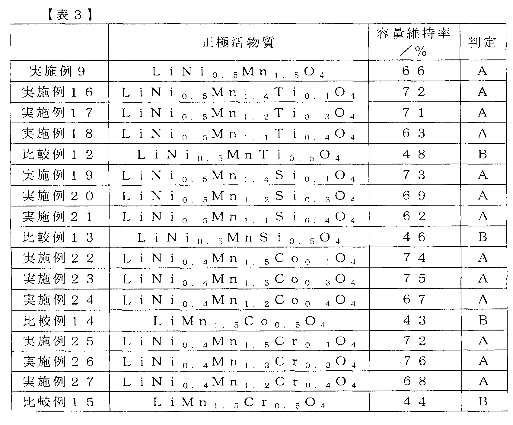
表3によると、正極活物質のM1量を示す前記式(1)のbが0以上、0.4以下の場合にリチウムイオン二次電池の容量維持率が50%以上となり、良好な急速充電特性が得られることが分かった。また、前記式(1)のbが前記範囲の場合は、M1がTi、Si、Co、Crのいずれであっても良好な容量維持率が得られることが分かった。
(実施例28~32、比較例16)
負極活物質の組成をLi4/3Ti5/3O4とし、比表面積を20m2g-1とした。正極活物質の比表面積を0.5m2g-1、M1量を0.1に固定し、M1のみを変えた電池を作製し、それぞれ実施例28~32及び比較例16とした。それらの容量維持率の評価結果を表4に示す。
負極活物質の組成をLi4/3Ti5/3O4とし、比表面積を20m2g-1とした。正極活物質の比表面積を0.5m2g-1、M1量を0.1に固定し、M1のみを変えた電池を作製し、それぞれ実施例28~32及び比較例16とした。それらの容量維持率の評価結果を表4に示す。
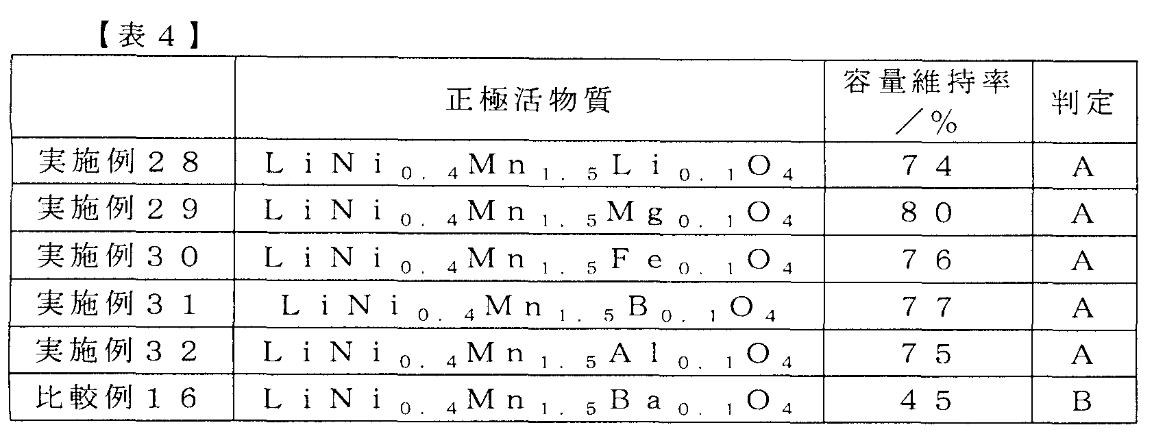
表4によると、M1がLi、Mg、Fe、B、Alの場合にリチウムイオン二次電池の容量維持率が50%以上となり、良好な急速充電特性が得られることが分かった。一方、Baによって置換した場合には所定の効果を得ることができなかった。この結果は、イオン化したBa(Ba2+)のイオン半径が置換されるNi2+のイオン半径の2倍以上と大きいことに関係しており、Niの置換元素には一定の制約があることを示すものである。
(実施例33~40)
負極活物質の組成をLi4/3Ti5/3O4とし、比表面積を20m2g-1とした。正極活物質の比表面積を0.5m2g-1に固定し、M1を2種以上とし、且つ組成をそれぞれ変更した電池を作製し、実施例33~40とした。それらの容量維持率の評価結果を表5に示す。
負極活物質の組成をLi4/3Ti5/3O4とし、比表面積を20m2g-1とした。正極活物質の比表面積を0.5m2g-1に固定し、M1を2種以上とし、且つ組成をそれぞれ変更した電池を作製し、実施例33~40とした。それらの容量維持率の評価結果を表5に示す。

表5では、M1としてTi、Si、Co、Fe、Cr、Al、Mg、B、Liの元素の、各々の組み合わせによって正極活物質のNiを置換した場合について、それぞれ評価を行った。表5の評価結果によると、これらのうちのどのような組み合わせであっても、リチウムイオン二次電池の容量維持率が50%以上となり、良好な急速充電特性が得られることが分かった。
(実施例41~45、比較例17、18)
正極活物質の組成をLiNi0.45Li0.05Mn1.4Ti0.1O4とし、比表面積を0.5m2g-1とした。負極活物質の比表面積を20m2g-1に固定し、負極活物質のM2、M2量である前記式(II)のcのみを変えた電池を作製し、それぞれ実施例41~45及び比較例17、18とした。それらの容量維持率の評価結果を表6に示す。
正極活物質の組成をLiNi0.45Li0.05Mn1.4Ti0.1O4とし、比表面積を0.5m2g-1とした。負極活物質の比表面積を20m2g-1に固定し、負極活物質のM2、M2量である前記式(II)のcのみを変えた電池を作製し、それぞれ実施例41~45及び比較例17、18とした。それらの容量維持率の評価結果を表6に示す。
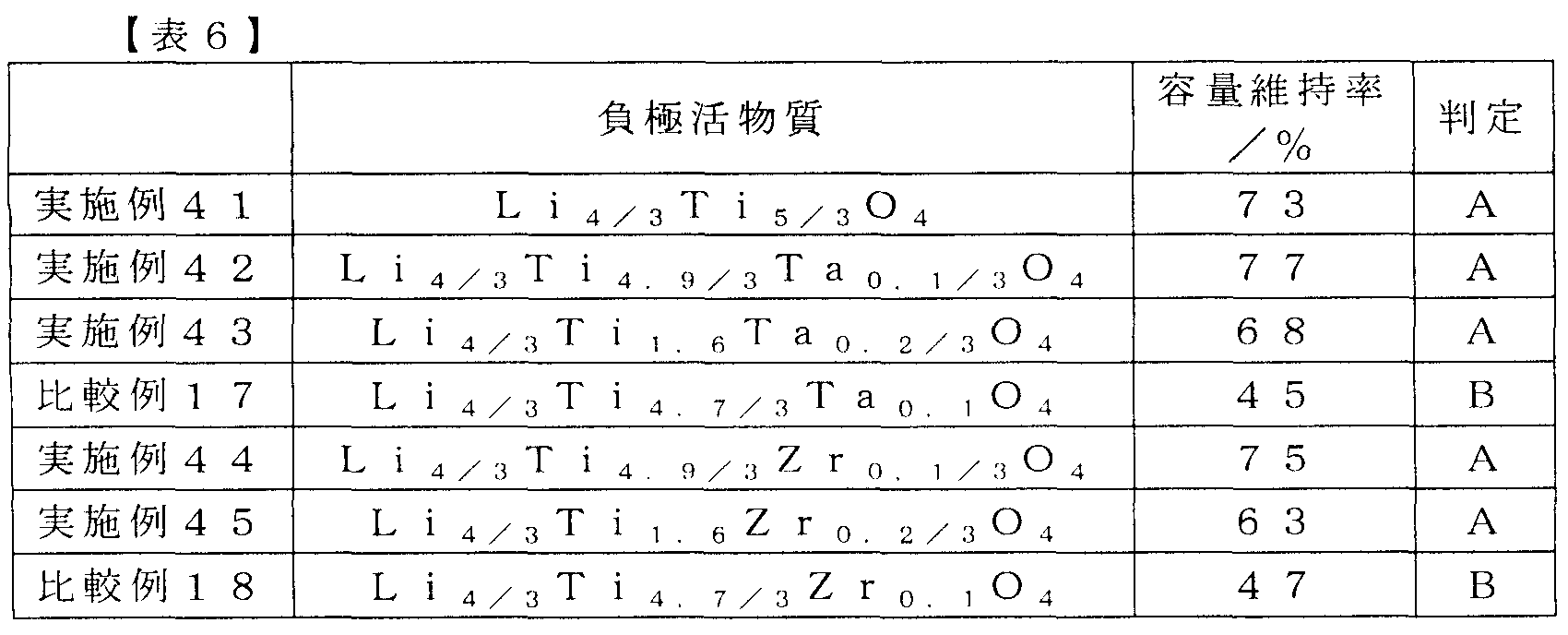
表6によると、前記式(II)のcが0.1未満の場合にリチウム二次電池の容量維持率が50%以上となり、良好な急速充電特性が得られることが分かった。また、前記式(II)のcが前記範囲の場合は、M2がTa、Zrのいずれであっても良好な容量維持率が得られることが分かった。
(実施例46~48、比較例19)
正極活物質の組成をLiNi0.4Li0.05Al0.05Mn1.4Si0.1O4とし、比表面積を0.5m2g-1とした。負極活物質の比表面積を20m2g-1に固定し、負極活物質のM2、M2量である前記式(II)のcのみを変えた電池を作製し、それぞれ実施例46~48及び比較例19とした。それらの容量維持率の評価結果を表7に示す。
正極活物質の組成をLiNi0.4Li0.05Al0.05Mn1.4Si0.1O4とし、比表面積を0.5m2g-1とした。負極活物質の比表面積を20m2g-1に固定し、負極活物質のM2、M2量である前記式(II)のcのみを変えた電池を作製し、それぞれ実施例46~48及び比較例19とした。それらの容量維持率の評価結果を表7に示す。

表7によると、M2として負極活物質のTiをCr、Ni、Vのいずれかの元素により置換した場合には、前記のTa又はZrによる場合と同様に、リチウムイオン二次電池の容量維持率は50%以上となり、良好な急速充電特性が得られることが分かった。一方、Agによって置換した場合には所定の効果を得ることができなかった。この結果は、イオン化したAg(Ag+)のイオン半径が、置換されるTi4+のイオン半径の2倍以上と大きいことに関係しており、Tiの置換元素には一定の制約があることを示すものである。
前記表1から表7に記載した一連の評価によって、以下のことが確認された。電解液と活物質間の界面反応場を規定するために比表面積を規定した前記式(I)のLixNiaM1bMn2-a-bO4で表される正極活物質と、同様に電解液と活物質間の界面反応場を規定するために比表面積を規定した前記式(II)のLiyTi5/3-cM2cO4で表される負極活物質とを用いてリチウムイオン二次電池を作製したが、該リチウムイオン二次電池は、60℃、90日間の高温保持を行った後であっても、十分に大きな容量維持率を維持することが可能であった。
以上により、本実施形態に係るリチウムイオン二次電池は、ユーザによる長時間の使用の後でも十分な急速充電特性を維持できるものと考えられる。したがって、本実施形態によれば、ユーザが実際に使用するための、高い信頼性を備えたリチウムイオン二次電池を提供することができる。すなわち、本実施形態により、急速充電が可能なリチウムイオン二次電池の提供が可能であることがわかった。
この出願は、2010年7月28日に出願された日本出願特願2010-169248を基礎とする優先権を主張し、その開示の全てをここに取り込む。
以上、実施形態及び実施例を参照して本願発明を説明したが、本願発明は上記実施形態及び実施例に限定されるものではない。本願発明の構成や詳細には、本願発明のスコープ内で当業者が理解し得る様々な変更をすることができる。
11 正極活物質
12 負極活物質
13 正極集電体
14 負極集電体
15 セパレータ
16、17 外装ラミネート
18 正極タブ
19 負極タブ
12 負極活物質
13 正極集電体
14 負極集電体
15 セパレータ
16、17 外装ラミネート
18 正極タブ
19 負極タブ
Claims (2)
- 正極と、負極と、を備えるリチウムイオン二次電池であって、
前記正極が、下記式(I)
LixNiaM1bMn2-a-bO4 (I)
(前記式(I)において、M1はTi、Si、Co、Fe、Cr、Al、Mg、B及びLiからなる群から選択される少なくとも一種を示す。0<x≦1、0.4≦a≦0.6、0≦b≦0.4である。)
で表され、比表面積が0.2m2g-1以上、1m2g-1以下であるリチウムニッケルマンガン酸化物を含み、
前記負極が、下記式(II)
LiyTi5/3-cM2cO4 (II)
(前記式(II)において、M2はTa、Zr、Cr、Ni及びVからなる群から選択される少なくとも一種を示す。4/3≦y≦7/3、0≦c<0.1である。)
で表され、比表面積が4m2g-1以上、20m2g-1以下であるリチウムチタン酸化物を含むリチウムイオン二次電池。 - 前記式(I)のM1が、Ti、Si、Fe及びCrからなる群から選択される少なくとも一種である請求項1に記載のリチウムイオン二次電池。
Priority Applications (3)
| Application Number | Priority Date | Filing Date | Title |
|---|---|---|---|
| US13/811,030 US20130122373A1 (en) | 2010-07-28 | 2011-07-22 | Lithium ion secondary battery |
| EP11812383.5A EP2600458B1 (en) | 2010-07-28 | 2011-07-22 | Lithium ion secondary battery |
| CN201180036920.3A CN103004005B (zh) | 2010-07-28 | 2011-07-22 | 锂离子二次电池 |
Applications Claiming Priority (2)
| Application Number | Priority Date | Filing Date | Title |
|---|---|---|---|
| JP2010-169248 | 2010-07-28 | ||
| JP2010169248A JP2012033279A (ja) | 2010-07-28 | 2010-07-28 | リチウムイオン二次電池 |
Publications (1)
| Publication Number | Publication Date |
|---|---|
| WO2012014793A1 true WO2012014793A1 (ja) | 2012-02-02 |
Family
ID=45530001
Family Applications (1)
| Application Number | Title | Priority Date | Filing Date |
|---|---|---|---|
| PCT/JP2011/066657 Ceased WO2012014793A1 (ja) | 2010-07-28 | 2011-07-22 | リチウムイオン二次電池 |
Country Status (5)
| Country | Link |
|---|---|
| US (1) | US20130122373A1 (ja) |
| EP (1) | EP2600458B1 (ja) |
| JP (1) | JP2012033279A (ja) |
| CN (1) | CN103004005B (ja) |
| WO (1) | WO2012014793A1 (ja) |
Cited By (8)
| Publication number | Priority date | Publication date | Assignee | Title |
|---|---|---|---|---|
| WO2013153690A1 (ja) * | 2012-04-13 | 2013-10-17 | 日本電気株式会社 | 二次電池用正極活物質及びそれを使用した二次電池 |
| WO2013161949A1 (ja) * | 2012-04-27 | 2013-10-31 | 三井金属鉱業株式会社 | マンガン系スピネル型リチウム遷移金属酸化物 |
| US20140349171A1 (en) * | 2012-04-16 | 2014-11-27 | Lg Chem, Ltd. | Method of manufacturing electrode for lithium secondary battery and electrode manufactured using the same |
| JP2015513182A (ja) * | 2012-04-16 | 2015-04-30 | エルジー・ケム・リミテッド | リチウム二次電池用電極の製造方法及びそれを用いて製造される電極 |
| EP2806491A4 (en) * | 2012-04-17 | 2015-06-17 | Lg Chemical Ltd | LITHIUM SECONDARY BATTERY WITH EXCELLENT PERFORMANCE |
| EP2811569A4 (en) * | 2012-04-17 | 2015-06-24 | Lg Chemical Ltd | LITHIUM SECONDARY BATTERY WITH EXCELLENT PERFORMANCE |
| EP2811570A4 (en) * | 2012-04-17 | 2015-06-24 | Lg Chemical Ltd | LITHIUM SECONDARY BATTERY WITH EXCELLENT PERFORMANCE |
| CN104956537A (zh) * | 2013-04-11 | 2015-09-30 | 株式会社Lg化学 | 包含具有不同表面积的电极的电极层压物和使用所述电极层压物的二次电池 |
Families Citing this family (40)
| Publication number | Priority date | Publication date | Assignee | Title |
|---|---|---|---|---|
| US9428396B2 (en) | 2011-04-28 | 2016-08-30 | Ishihara Sangyo Kaisha, Ltd | Method for producing lithium titanate precursor, method for producing lithium titanate, lithium titanate, electrode active material, and electricity storage device |
| JP2013178916A (ja) * | 2012-02-28 | 2013-09-09 | Murata Mfg Co Ltd | 非水電解質二次電池 |
| CN104321915A (zh) * | 2012-04-17 | 2015-01-28 | 株式会社Lg化学 | 制造锂二次电池用电极的方法和使用其制造的电极 |
| KR101497351B1 (ko) * | 2012-04-17 | 2015-03-03 | 주식회사 엘지화학 | 과량의 전해액을 포함하는 리튬 이차전지 |
| KR101495301B1 (ko) | 2012-04-18 | 2015-02-25 | 주식회사 엘지화학 | 이차전지용 전극 및 이를 포함하는 이차전지 |
| KR101497348B1 (ko) * | 2012-04-18 | 2015-03-05 | 주식회사 엘지화학 | 리튬 이차전지용 일체형 전극조립체의 제조방법 및 이를 사용하여 제조되는 일체형 전극조립체 |
| KR101483205B1 (ko) * | 2012-04-18 | 2015-01-16 | 주식회사 엘지화학 | 전해액 함침성 및 안전성이 향상된 전극조립체 및 이를 포함하는 리튬 이차전지 |
| KR101493255B1 (ko) * | 2012-04-19 | 2015-02-16 | 주식회사 엘지화학 | 전극의 제조방법 및 이를 사용하여 제조되는 전극 |
| JP6319305B2 (ja) * | 2012-06-01 | 2018-05-09 | ソルベー エスアー | リチウムイオンバッテリ |
| KR101555833B1 (ko) | 2012-06-29 | 2015-09-30 | 주식회사 엘지화학 | 전극조립체 및 이를 포함하는 리튬 이차전지 |
| JP6386840B2 (ja) * | 2013-09-13 | 2018-09-05 | 株式会社東芝 | 非水電解質二次電池および電池パック |
| CN103700840A (zh) * | 2014-01-08 | 2014-04-02 | 山东精工电子科技有限公司 | 一种高电压锂电池正极材料及其制备方法 |
| CN103872312B (zh) * | 2014-03-10 | 2017-02-01 | 电子科技大学 | 锂离子电池正极材料LiMn2‑2xM(II)xTixO4及其制备方法 |
| CN103872313B (zh) * | 2014-03-10 | 2017-04-05 | 电子科技大学 | 锂离子电池正极材料LiMn2‑2xM(II)xSixO4及其制备方法 |
| JP6350321B2 (ja) * | 2014-03-24 | 2018-07-04 | 日亜化学工業株式会社 | 非水電解液二次電池用正極活物質 |
| WO2015151376A1 (ja) * | 2014-04-03 | 2015-10-08 | ソニー株式会社 | 二次電池、電池パック、電子機器、電動車両、蓄電装置および電力システム |
| JP6593324B2 (ja) * | 2014-04-03 | 2019-10-23 | 株式会社村田製作所 | 二次電池、電池パック、電子機器、電動車両、蓄電装置および電力システム |
| JP2015201335A (ja) * | 2014-04-08 | 2015-11-12 | 日立化成株式会社 | リチウムイオン電池 |
| US20170214044A1 (en) * | 2014-07-25 | 2017-07-27 | Advanced Lithium Electrochemistry Co., Ltd. | Method of preparing lithium nickel manganese oxide cathode material |
| DE112016001116T5 (de) * | 2015-03-10 | 2017-11-30 | The University Of Tokyo | Elektrolytlösung |
| JP6128196B2 (ja) * | 2015-03-24 | 2017-05-17 | 日亜化学工業株式会社 | 非水電解液二次電池用正極活物質 |
| US9966601B2 (en) | 2015-03-24 | 2018-05-08 | Nichia Corporation | Positive electrode active material for nonaqueous electrolyte secondary battery |
| JP6308396B2 (ja) * | 2015-04-10 | 2018-04-11 | トヨタ自動車株式会社 | 非水電解液二次電池 |
| CN108352561B (zh) * | 2015-11-06 | 2021-10-15 | 昭和电工材料株式会社 | 锂离子二次电池 |
| FR3045211B1 (fr) * | 2015-12-09 | 2020-06-05 | Commissariat A L'energie Atomique Et Aux Energies Alternatives | Materiau de cathode pour batteries li-ion |
| KR20230122178A (ko) | 2016-08-25 | 2023-08-22 | 토프쉐 에이/에스 | 고 전압 2차 배터리를 위한 캐소드 활성 물질 |
| KR102272269B1 (ko) * | 2016-10-10 | 2021-07-02 | 삼성에스디아이 주식회사 | 리튬 이차 전지용 양극 및 이를 포함하는 리튬 이차 전지 |
| TWI645607B (zh) * | 2016-12-30 | 2018-12-21 | 財團法人工業技術研究院 | 鋰電池高電壓正極材料及其製備方法 |
| US11978904B2 (en) | 2017-02-24 | 2024-05-07 | Honeycomb Battery Company | Polymer binder for lithium battery and method of manufacturing |
| US10840502B2 (en) | 2017-02-24 | 2020-11-17 | Global Graphene Group, Inc. | Polymer binder for lithium battery and method of manufacturing |
| US11742475B2 (en) | 2017-04-03 | 2023-08-29 | Global Graphene Group, Inc. | Encapsulated anode active material particles, lithium secondary batteries containing same, and method of manufacturing |
| US11329320B2 (en) * | 2017-06-08 | 2022-05-10 | National Institute For Materials Science | Non-aqueous electrolyte for lithium air batteries, and lithium air battery using the same |
| KR102308723B1 (ko) * | 2017-10-19 | 2021-10-05 | 주식회사 엘지에너지솔루션 | 음극 활물질, 상기 음극 활물질을 포함하는 음극, 및 상기 음극을 포함하는 이차 전지 |
| CN108448109B (zh) * | 2018-03-23 | 2021-07-02 | 中南大学 | 一种层状富锂锰基正极材料及其制备方法 |
| US12218346B2 (en) | 2018-06-21 | 2025-02-04 | Honeycomb Battery Company | Method of extending cycle-life of a lithium metal secondary battery |
| US12288883B2 (en) * | 2018-06-21 | 2025-04-29 | Honeycomb Battery Company | Method of improving cycle-life of a lithium metal secondary battery |
| US11223049B2 (en) | 2018-08-24 | 2022-01-11 | Global Graphene Group, Inc. | Method of producing protected particles of cathode active materials for lithium batteries |
| US11637291B2 (en) | 2020-11-04 | 2023-04-25 | Global Graphene Group, Inc. | Lithium-protecting polymer layer for an anode-less lithium metal secondary battery and manufacturing method |
| JP7325469B2 (ja) * | 2021-03-30 | 2023-08-14 | プライムプラネットエナジー&ソリューションズ株式会社 | 非水電解液二次電池の製造方法 |
| KR102783239B1 (ko) * | 2022-02-28 | 2025-03-19 | 가부시끼가이샤 레조낙 | 리튬 이온 전도성 고체 전해질 |
Citations (7)
| Publication number | Priority date | Publication date | Assignee | Title |
|---|---|---|---|---|
| JP2000156229A (ja) | 1998-11-20 | 2000-06-06 | Yuasa Corp | 非水電解質リチウム二次電池 |
| JP2000235857A (ja) | 1998-12-18 | 2000-08-29 | Sanyo Electric Co Ltd | リチウム二次電池 |
| JP2001176557A (ja) | 1999-12-20 | 2001-06-29 | Toyota Central Res & Dev Lab Inc | 非水電解液二次電池 |
| JP2005317512A (ja) * | 2004-03-31 | 2005-11-10 | Toshiba Corp | 非水電解質電池 |
| JP2006066341A (ja) | 2004-08-30 | 2006-03-09 | Toshiba Corp | 非水電解質二次電池 |
| JP2007087875A (ja) * | 2005-09-26 | 2007-04-05 | Toshiba Corp | 非水電解質電池および電池パック |
| JP2010169248A (ja) | 2008-12-26 | 2010-08-05 | Hitachi Automotive Systems Ltd | ディスクブレーキ |
Family Cites Families (21)
| Publication number | Priority date | Publication date | Assignee | Title |
|---|---|---|---|---|
| JPH1027609A (ja) * | 1996-07-09 | 1998-01-27 | Matsushita Electric Ind Co Ltd | 非水電解液二次電池 |
| JPH10172571A (ja) * | 1996-12-16 | 1998-06-26 | Aichi Steel Works Ltd | リチウム二次電池及びその正極活物質の製造方法 |
| JP2000058058A (ja) * | 1998-08-03 | 2000-02-25 | Masayuki Yoshio | リチウム二次電池用スピネル系マンガン酸化物 |
| JP3595734B2 (ja) * | 1999-02-15 | 2004-12-02 | 株式会社デンソー | 非水電解液二次電池用正極活物質、その正極活物質の製法、及びその正極活物質を用いた二次電池 |
| JP2002042814A (ja) * | 2000-07-28 | 2002-02-08 | Hitachi Maxell Ltd | 非水二次電池用正極活物質およびそれを用いた非水二次電池 |
| JP2002145617A (ja) * | 2000-11-09 | 2002-05-22 | Nippon Chem Ind Co Ltd | リチウムマンガン複合酸化物およびその製造方法 |
| JP5013386B2 (ja) * | 2000-11-17 | 2012-08-29 | 日立マクセルエナジー株式会社 | 非水二次電池用正極活物質およびそれを用いた非水二次電池 |
| JP2003115324A (ja) * | 2001-10-04 | 2003-04-18 | Japan Storage Battery Co Ltd | 非水電解質電池。 |
| JP4325167B2 (ja) * | 2001-10-18 | 2009-09-02 | 日本電気株式会社 | 非水電解液二次電池用電極材料 |
| JP4192477B2 (ja) * | 2002-03-08 | 2008-12-10 | 日本電気株式会社 | 二次電池用正極活物質およびそれを用いた二次電池用正極および二次電池 |
| JP4541709B2 (ja) * | 2002-03-27 | 2010-09-08 | 株式会社Gsユアサ | 正極活物質およびそれを用いた非水電解質電池 |
| JP2006219323A (ja) * | 2005-02-09 | 2006-08-24 | Sumitomo Metal Mining Co Ltd | リチウムマンガンニッケルアルミニウム複合酸化物およびその製造方法 |
| JP4213688B2 (ja) * | 2005-07-07 | 2009-01-21 | 株式会社東芝 | 非水電解質電池及び電池パック |
| JP4213687B2 (ja) * | 2005-07-07 | 2009-01-21 | 株式会社東芝 | 非水電解質電池及び電池パック |
| JP5068459B2 (ja) * | 2006-01-25 | 2012-11-07 | Necエナジーデバイス株式会社 | リチウム二次電池 |
| JP4334579B2 (ja) * | 2007-03-28 | 2009-09-30 | 株式会社東芝 | 非水電解質電池用負極活物質、非水電解質電池、電池パック及び自動車 |
| JP5115697B2 (ja) * | 2007-05-22 | 2013-01-09 | Necエナジーデバイス株式会社 | リチウム二次電池用正極及びそれを用いたリチウム二次電池 |
| JP5300502B2 (ja) * | 2008-03-13 | 2013-09-25 | 株式会社東芝 | 電池用活物質、非水電解質電池および電池パック |
| CN101567442A (zh) * | 2008-07-28 | 2009-10-28 | 新乡市中科科技有限公司 | 一种尖晶石复合钛酸锂的制备方法 |
| JP5258499B2 (ja) * | 2008-10-15 | 2013-08-07 | 日立マクセル株式会社 | 非水二次電池 |
| CN101764207B (zh) * | 2009-09-25 | 2012-01-18 | 合肥工业大学 | 一种锂离子电池负极材料钛酸锂及其制备方法 |
-
2010
- 2010-07-28 JP JP2010169248A patent/JP2012033279A/ja active Pending
-
2011
- 2011-07-22 CN CN201180036920.3A patent/CN103004005B/zh active Active
- 2011-07-22 US US13/811,030 patent/US20130122373A1/en not_active Abandoned
- 2011-07-22 EP EP11812383.5A patent/EP2600458B1/en active Active
- 2011-07-22 WO PCT/JP2011/066657 patent/WO2012014793A1/ja not_active Ceased
Patent Citations (7)
| Publication number | Priority date | Publication date | Assignee | Title |
|---|---|---|---|---|
| JP2000156229A (ja) | 1998-11-20 | 2000-06-06 | Yuasa Corp | 非水電解質リチウム二次電池 |
| JP2000235857A (ja) | 1998-12-18 | 2000-08-29 | Sanyo Electric Co Ltd | リチウム二次電池 |
| JP2001176557A (ja) | 1999-12-20 | 2001-06-29 | Toyota Central Res & Dev Lab Inc | 非水電解液二次電池 |
| JP2005317512A (ja) * | 2004-03-31 | 2005-11-10 | Toshiba Corp | 非水電解質電池 |
| JP2006066341A (ja) | 2004-08-30 | 2006-03-09 | Toshiba Corp | 非水電解質二次電池 |
| JP2007087875A (ja) * | 2005-09-26 | 2007-04-05 | Toshiba Corp | 非水電解質電池および電池パック |
| JP2010169248A (ja) | 2008-12-26 | 2010-08-05 | Hitachi Automotive Systems Ltd | ディスクブレーキ |
Cited By (21)
| Publication number | Priority date | Publication date | Assignee | Title |
|---|---|---|---|---|
| WO2013153690A1 (ja) * | 2012-04-13 | 2013-10-17 | 日本電気株式会社 | 二次電池用正極活物質及びそれを使用した二次電池 |
| US9236602B2 (en) | 2012-04-13 | 2016-01-12 | Nec Corporation | Positive electrode active material for secondary battery and secondary battery using the same |
| JPWO2013153690A1 (ja) * | 2012-04-13 | 2015-12-17 | 日本電気株式会社 | 二次電池用正極活物質及びそれを使用した二次電池 |
| JP2015513182A (ja) * | 2012-04-16 | 2015-04-30 | エルジー・ケム・リミテッド | リチウム二次電池用電極の製造方法及びそれを用いて製造される電極 |
| US9780359B2 (en) | 2012-04-16 | 2017-10-03 | Lg Chem, Ltd. | Method of manufacturing electrode for lithium secondary battery and electrode manufactured using the same |
| US20140349171A1 (en) * | 2012-04-16 | 2014-11-27 | Lg Chem, Ltd. | Method of manufacturing electrode for lithium secondary battery and electrode manufactured using the same |
| US10026952B2 (en) * | 2012-04-16 | 2018-07-17 | Lg Chem, Ltd. | Method of manufacturing electrode for lithium secondary battery and electrode manufactured using the same |
| EP2811570A4 (en) * | 2012-04-17 | 2015-06-24 | Lg Chemical Ltd | LITHIUM SECONDARY BATTERY WITH EXCELLENT PERFORMANCE |
| US9825293B2 (en) | 2012-04-17 | 2017-11-21 | Lg Chem, Ltd. | Lithium battery having higher performance |
| EP2806491A4 (en) * | 2012-04-17 | 2015-06-17 | Lg Chemical Ltd | LITHIUM SECONDARY BATTERY WITH EXCELLENT PERFORMANCE |
| US9899663B2 (en) | 2012-04-17 | 2018-02-20 | Lg Chem, Ltd. | Lithium secondary battery with excellent performance |
| EP2811569A4 (en) * | 2012-04-17 | 2015-06-24 | Lg Chemical Ltd | LITHIUM SECONDARY BATTERY WITH EXCELLENT PERFORMANCE |
| US9564635B2 (en) | 2012-04-17 | 2017-02-07 | Lg Chem, Ltd. | Lithium secondary battery with excellent performance |
| US9537140B2 (en) | 2012-04-27 | 2017-01-03 | Mitsui Mining & Smelting Co., Ltd. | Manganese spinel-type lithium transition metal oxide |
| WO2013161949A1 (ja) * | 2012-04-27 | 2013-10-31 | 三井金属鉱業株式会社 | マンガン系スピネル型リチウム遷移金属酸化物 |
| GB2516185A (en) * | 2012-04-27 | 2015-01-14 | Mitsui Mining & Smelting Co | Manganese spinel-type lithium transition metal oxide |
| JP5523637B2 (ja) * | 2012-04-27 | 2014-06-18 | 三井金属鉱業株式会社 | マンガン系スピネル型リチウム遷移金属酸化物 |
| EP2919314A4 (en) * | 2013-04-11 | 2016-05-25 | Lg Chemical Ltd | ELECTRODE LAMINATE WITH ELECTRODES WITH VARIOUS AREAS AND SECONDARY BATTERY THEREWITH |
| US9666909B2 (en) | 2013-04-11 | 2017-05-30 | Lg Chem, Ltd. | Electrode laminate comprising electrodes with different surface areas and secondary battery employed with the same |
| CN104956537B (zh) * | 2013-04-11 | 2018-01-26 | 株式会社Lg 化学 | 包含具有不同表面积的电极的电极层压物和使用所述电极层压物的二次电池 |
| CN104956537A (zh) * | 2013-04-11 | 2015-09-30 | 株式会社Lg化学 | 包含具有不同表面积的电极的电极层压物和使用所述电极层压物的二次电池 |
Also Published As
| Publication number | Publication date |
|---|---|
| EP2600458A1 (en) | 2013-06-05 |
| EP2600458B1 (en) | 2018-03-14 |
| EP2600458A4 (en) | 2016-08-24 |
| US20130122373A1 (en) | 2013-05-16 |
| JP2012033279A (ja) | 2012-02-16 |
| CN103004005A (zh) | 2013-03-27 |
| CN103004005B (zh) | 2016-05-25 |
Similar Documents
| Publication | Publication Date | Title |
|---|---|---|
| CN103004005B (zh) | 锂离子二次电池 | |
| JP5495300B2 (ja) | リチウムイオン二次電池 | |
| JP5641560B2 (ja) | 二次電池用正極活物質及びそれを使用した二次電池 | |
| JP5278994B2 (ja) | リチウム二次電池 | |
| JP6607188B2 (ja) | 正極及びそれを用いた二次電池 | |
| US9356284B2 (en) | Active material for secondary battery | |
| JP6762377B2 (ja) | リチウムイオン二次電池 | |
| JPWO2012165020A1 (ja) | 二次電池用活物質およびそれを使用した二次電池 | |
| CN110073534B (zh) | 非水电解质二次电池 | |
| JP5483413B2 (ja) | リチウムイオン二次電池 | |
| JP2009187807A (ja) | 二次電池用正極およびこれを使用したリチウム二次電池 | |
| JPWO2014171518A1 (ja) | リチウムイオン二次電池 | |
| JP5376640B2 (ja) | リチウムイオン二次電池 | |
| JP5046602B2 (ja) | 二次電池用正極、およびそれを用いた二次電池 | |
| CN103210532B (zh) | 二次电池用正极活性物质和使用其的二次电池 | |
| JP5360870B2 (ja) | リチウムイオン二次電池用正極、およびそれを用いたリチウムイオン二次電池 | |
| CN112005410B (zh) | 非水电解质二次电池用正极活性物质和非水电解质二次电池 | |
| JP4867153B2 (ja) | 非水電解液二次電池用の正極活物質、二次電池用正極および非水電解液二次電池 | |
| JP5605867B2 (ja) | 二次電池用正極およびこれを使用したリチウム二次電池 | |
| JP4991225B2 (ja) | 二次電池用正極活物質、それを用いた二次電池用正極および二次電池 | |
| KR20250043189A (ko) | 양극 활물질, 이를 포함하는 양극 및 리튬 이차 전지 |
Legal Events
| Date | Code | Title | Description |
|---|---|---|---|
| 121 | Ep: the epo has been informed by wipo that ep was designated in this application |
Ref document number: 11812383 Country of ref document: EP Kind code of ref document: A1 |
|
| WWE | Wipo information: entry into national phase |
Ref document number: 2011812383 Country of ref document: EP |
|
| WWE | Wipo information: entry into national phase |
Ref document number: 13811030 Country of ref document: US |
|
| NENP | Non-entry into the national phase |
Ref country code: DE |