WO2012015051A1 - 燃料電池バンドルおよびこれを備えた燃料電池モジュール - Google Patents
燃料電池バンドルおよびこれを備えた燃料電池モジュール Download PDFInfo
- Publication number
- WO2012015051A1 WO2012015051A1 PCT/JP2011/067541 JP2011067541W WO2012015051A1 WO 2012015051 A1 WO2012015051 A1 WO 2012015051A1 JP 2011067541 W JP2011067541 W JP 2011067541W WO 2012015051 A1 WO2012015051 A1 WO 2012015051A1
- Authority
- WO
- WIPO (PCT)
- Prior art keywords
- fuel cell
- fuel
- flow path
- cell stack
- gas flow
- Prior art date
- Legal status (The legal status is an assumption and is not a legal conclusion. Google has not performed a legal analysis and makes no representation as to the accuracy of the status listed.)
- Ceased
Links
Images




Classifications
-
- H—ELECTRICITY
- H01—ELECTRIC ELEMENTS
- H01M—PROCESSES OR MEANS, e.g. BATTERIES, FOR THE DIRECT CONVERSION OF CHEMICAL ENERGY INTO ELECTRICAL ENERGY
- H01M8/00—Fuel cells; Manufacture thereof
- H01M8/24—Grouping of fuel cells, e.g. stacking of fuel cells
- H01M8/249—Grouping of fuel cells, e.g. stacking of fuel cells comprising two or more groupings of fuel cells, e.g. modular assemblies
-
- H—ELECTRICITY
- H01—ELECTRIC ELEMENTS
- H01M—PROCESSES OR MEANS, e.g. BATTERIES, FOR THE DIRECT CONVERSION OF CHEMICAL ENERGY INTO ELECTRICAL ENERGY
- H01M8/00—Fuel cells; Manufacture thereof
- H01M8/02—Details
-
- H—ELECTRICITY
- H01—ELECTRIC ELEMENTS
- H01M—PROCESSES OR MEANS, e.g. BATTERIES, FOR THE DIRECT CONVERSION OF CHEMICAL ENERGY INTO ELECTRICAL ENERGY
- H01M8/00—Fuel cells; Manufacture thereof
- H01M8/24—Grouping of fuel cells, e.g. stacking of fuel cells
- H01M8/241—Grouping of fuel cells, e.g. stacking of fuel cells with solid or matrix-supported electrolytes
- H01M8/2425—High-temperature cells with solid electrolytes
-
- H—ELECTRICITY
- H01—ELECTRIC ELEMENTS
- H01M—PROCESSES OR MEANS, e.g. BATTERIES, FOR THE DIRECT CONVERSION OF CHEMICAL ENERGY INTO ELECTRICAL ENERGY
- H01M8/00—Fuel cells; Manufacture thereof
- H01M8/24—Grouping of fuel cells, e.g. stacking of fuel cells
- H01M8/241—Grouping of fuel cells, e.g. stacking of fuel cells with solid or matrix-supported electrolytes
- H01M8/2425—High-temperature cells with solid electrolytes
- H01M8/243—Grouping of unit cells of tubular or cylindrical configuration
-
- H—ELECTRICITY
- H01—ELECTRIC ELEMENTS
- H01M—PROCESSES OR MEANS, e.g. BATTERIES, FOR THE DIRECT CONVERSION OF CHEMICAL ENERGY INTO ELECTRICAL ENERGY
- H01M8/00—Fuel cells; Manufacture thereof
- H01M8/24—Grouping of fuel cells, e.g. stacking of fuel cells
- H01M8/2465—Details of groupings of fuel cells
-
- H—ELECTRICITY
- H01—ELECTRIC ELEMENTS
- H01M—PROCESSES OR MEANS, e.g. BATTERIES, FOR THE DIRECT CONVERSION OF CHEMICAL ENERGY INTO ELECTRICAL ENERGY
- H01M8/00—Fuel cells; Manufacture thereof
- H01M8/10—Fuel cells with solid electrolytes
- H01M8/12—Fuel cells with solid electrolytes operating at high temperature, e.g. with stabilised ZrO2 electrolyte
- H01M2008/1293—Fuel cells with solid oxide electrolytes
-
- Y—GENERAL TAGGING OF NEW TECHNOLOGICAL DEVELOPMENTS; GENERAL TAGGING OF CROSS-SECTIONAL TECHNOLOGIES SPANNING OVER SEVERAL SECTIONS OF THE IPC; TECHNICAL SUBJECTS COVERED BY FORMER USPC CROSS-REFERENCE ART COLLECTIONS [XRACs] AND DIGESTS
- Y02—TECHNOLOGIES OR APPLICATIONS FOR MITIGATION OR ADAPTATION AGAINST CLIMATE CHANGE
- Y02E—REDUCTION OF GREENHOUSE GAS [GHG] EMISSIONS, RELATED TO ENERGY GENERATION, TRANSMISSION OR DISTRIBUTION
- Y02E60/00—Enabling technologies; Technologies with a potential or indirect contribution to GHG emissions mitigation
- Y02E60/30—Hydrogen technology
- Y02E60/50—Fuel cells
Definitions
- the present invention relates to a fuel cell bundle and a fuel cell module including the same.
- a fuel cell stack in which a plurality of fuel cells are electrically connected via an interconnector is known.
- a fuel electrode, a solid electrolyte, and an air electrode are laminated in this order on the side surface of an electrically insulating support.
- a fuel cell bundle in which a plurality of fuel cell stacks are arranged in a staggered manner and the adjacent fuel cell stacks are electrically connected via a connecting member is known (see Patent Document 1).
- Patent Document 1 even if fuel cell stacks are arranged in a staggered manner and a large amount of reaction gas is supplied between the fuel cell stacks, the reaction supplied between adjacent fuel cell stacks Gas flows out from between the fuel cell stacks to the side, and a sufficient amount of reaction gas cannot be efficiently supplied to the fuel cells constituting the fuel cell stack, making it difficult to increase the power generation efficiency of the fuel cell bundle. There was a problem.
- an object of the present invention is to provide a fuel cell bundle capable of efficiently supplying a sufficient amount of reaction gas to the fuel cell stack and a fuel cell module including the same.
- the fuel cell bundle of the present invention comprises a plurality of columnar fuel cell stacks extending in a first direction and arranged such that the side surfaces of the fuel cell stacks are opposed to each other, and the fuel cell
- the stack includes a plurality of fuels having a first gas flow path along the first direction and arranged side by side in a second direction intersecting the first direction and connected in series.
- a connecting member that electrically connects the fuel cells of the adjacent fuel cell stacks between the adjacent fuel cell stacks, and the first between the connecting members.
- a second gas flow path regulating member for forming a second gas flow path along the gas flow path.
- the fuel cell module of the present invention is obtained by storing the above fuel cell bundle in a storage container.
- a sufficient amount of reaction gas can be efficiently supplied to the fuel cells constituting the fuel cell stack, and the power generation output of the fuel cell bundle can be improved.
- FIG. 2 It is a front view which shows the fuel cell stack which comprises a fuel cell bundle.
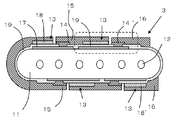
- FIG. 2 is a cross-sectional view taken along line AA of the fuel cell stack shown in FIG. It is an expanded sectional view showing the detailed structure of a fuel cell.
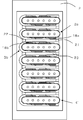
- (A) is sectional drawing of the fuel cell bundle of a 1st form
- (b) is a side view of the fuel cell bundle of (a).
- FIG. 5A shows an adjacent fuel cell stack
- FIG. 4A shows a fuel cell bundle according to a fourth embodiment in which the fuel cells on opposite side surfaces of the adjacent fuel cell stack are arranged so as to be positioned between them.
- Explanatory drawing (b) is explanatory drawing which shows the fuel cell bundle of the 5th form arrange
- the fuel cell stack 3 used for the fuel cell bundle will be described with reference to FIGS.
- description of the connection member between cells is abbreviate
- the thickness, length, width, etc. may be shown enlarged or reduced for easy understanding.
- the fuel cell stack 3 has a columnar shape extending in the first direction.
- a plurality of rectangular cells are formed on the side surface of the elongated hollow plate-like support body 11 along the length direction of the support body 11.
- the fuel cells 13 are formed side by side in a second direction intersecting the first direction. Therefore, the length direction of the fuel cell stack 3 is the first direction.
- the support 11 is a cross section, but the oblique lines are omitted. Further, the first direction and the second direction are not necessarily orthogonal to each other.
- a total of four fuel cells 13 are formed, two on one side of the hollow plate-like support 11 and two on the other side.
- each of the plurality of fuel cells 13 has an elongated rectangular shape having a long side and a short side as viewed from the front, and the extending direction of the long side is the length direction of the support 11. .
- a plurality of adjacent long sides of the fuel cell 13 are opposed to each other. Since the length direction of the support body 1 is also the first direction, the first direction is sometimes referred to as the length direction of the support body 11. Further, since the width direction of the support 11 is also a second direction intersecting with the first direction, the second direction may be referred to as the width direction of the support 1.
- the support 11 has a pair of flat side surfaces facing each other, and both sides of each side surface are connected by an isolated surface, and has an elliptical columnar shape.
- One or more (six in the figure) independent first gas passages 12 penetrating from one end portion to the other end portion in the length direction of the support 11 are formed in the length direction of the support plate 11 (see FIG. 2 in the direction perpendicular to the paper surface).
- a fuel cell hydrogen gas
- Fuel gas is supplied to the cell 13.
- the support 11 is formed of an insulating material from the viewpoint of preventing an electrical short circuit between the fuel cells 13.
- the width D of the support 11 (corresponding to the distance between the arcuate surfaces at both ends) D is, for example, in the range of 15 mm to 80 mm, preferably 30 mm to 80 mm, and the length dimension L is, for example, 100 mm. It is in the range of ⁇ 300 mm, preferably 150 mm to 250 mm.
- the support 11 is made porous, and the open porosity thereof is, for example, 25% or more, preferably 30% to 45%. Thereby, the fuel gas in the first gas flow path 12 can be introduced to the surface of the fuel electrode 17.
- FIG. 1 shows a fuel cell stack. In this figure, the width D and the length L of the support 11 are shown.
- the fuel cell 13 is configured by laminating a fuel electrode 17 as an inner electrode, a solid electrolyte 19 and an air electrode 18 as an outer electrode, and a portion where the fuel electrode 17, the solid electrolyte 19 and the air electrode 18 overlap. Functions as a power generation unit.
- the fuel cell 13 is stacked on the side surface of the support 11.
- the solid electrolyte 19 is provided with an opening along the longitudinal direction of the fuel battery cell 13, and a conductive interconnector 14 is formed here and connected to the fuel electrode 17 provided on the support 11. .
- the interconnector 14 has a function of drawing the current generated by the fuel battery cell 13 to the surface of the adjacent fuel battery cell 13.
- the air electrode 18 of the fuel battery cell 13 and the interconnector 14 of the fuel battery cell 13 adjacent to the fuel battery cell 13 are connected by a cell connecting member 15 so that the four fuel battery cells 13 are electrically connected in series. It is connected.
- a cell connection member 15 is formed on the left arcuate surface portion in FIG. 2.
- a cell stack connection for electrically connecting the adjacent fuel cell stack 3 to the interconnector 14 of the fuel cells at both ends connected in series and the air electrode 18.
- the member 16 is connected.
- FIG. 3 is an enlarged cross-sectional view showing the detailed structure of the fuel battery cell 13.
- a diffusion prevention layer 11a for preventing diffusion of the support material is formed on the entire surface of the support 11.
- a fuel electrode 17 that allows hydrogen gas to pass therethrough is formed thereon in accordance with the shape of the fuel battery cell 13.
- the fuel electrode 17 is composed of two layers of a current collecting fuel electrode 17a and an active fuel electrode 17b.
- a solid electrolyte 19 is formed on the fuel electrode 17.
- the solid electrolyte 19 is formed so as to cover the fuel electrode 17 and the support 11 other than the opening where the interconnector 14 described later is provided, and is also formed between the adjacent fuel cells 13. Thereby, it is possible to reduce the gas leakage of the fuel gas flowing through the first gas flow path 12 provided in the support 11.
- the solid electrolyte 19 is provided with an opening extending in the direction along the long side of the fuel cell 13, and an interconnector 14 for taking out electricity from the fuel electrode 17 is formed in the opening.
- the interconnector 14 has a two-layer structure of a metal layer 14a and a metal glass layer 14b.
- the metal glass layer 14 b is used, but instead of the metal glass layer 14 b, for example, (La, Sr) CrO 3 , (La, Sr) ( Co, Fe) O 3 , (La, Sr) MnO 3 or the like can be used.
- an air electrode 18 is formed on the solid electrolyte 19 via a reaction preventing layer 20 for preventing a reaction between the air electrode 18 and the solid electrolyte 19. Since the positive and negative electricity of the fuel cell 13 is taken out from the air electrode 18 and the interconnector 14, the air electrode 18 and the interconnector 14 are arranged so as not to contact each other.
- the cell connection member 15 is a conductive member for connecting the air electrode 18 of one fuel battery cell 13 and the interconnector 14 of another fuel battery cell 13 adjacent thereto.
- the cell connecting member 15 may be a single member extending along the longitudinal direction of the fuel cell 13 or may be composed of a plurality of members that connect a plurality of locations of the fuel cells 13. By this cell connection member 15, the fuel cells 13 arranged from one end portion to the other end portion in the longitudinal direction of the support 11 are electrically connected in series.
- a porous cell stack connection member 16 is formed on the fuel cell 13 positioned on the right side of the fuel cell stack 3 to be electrically connected to the adjacent fuel cell stack 3.
- the cell stack connection member 16 can be made of the same material as the cell connection member 15 described above.
- the fuel cell 13 located on the right side of the first fuel cell stack 3 and the second The fuel cell 13 positioned on the right side of the fuel cell stack 3 can be electrically connected via the cell stack connection member 16 and a connection member 21 described later.
- the cell 13 is electrically connected by being disposed so as to wrap around the cell connection member 15 via the interconnector 14. Even the fuel cells 13 provided on the upper and lower surfaces of the support 11 are said to be adjacent to each other if they are connected by the cell connection member 15.
- adjacent fuel cells 13 are electrically connected by the cell connecting member 15. That is, the fuel electrode 17 of one fuel cell 13 is connected to the air electrode 18 of the other adjacent fuel cell 13 by the cell connecting member 15 via the interconnector 14.
- the interconnector 14 ′ of the fuel cell 13 on the right side of the support 11 serves as a pole to be connected to the fuel cell stack 3 arranged next to it.
- the air electrode 18 ′ of the right fuel cell 13 of the same support 11 is also an electrode for connection to the adjacent fuel cell stack 3.
- a connection member (not shown) is formed as will be described in detail later.
- the amount of fuel gas supplied to the fuel cells located downstream of the fuel gas is:
- fuel depletion may occur that is less than the amount of fuel gas used for power generation of the fuel cell located upstream and supplied to the fuel cell 13 located upstream of the fuel gas.
- the long sides of the fuel cells 13 provided from one end to the other end on the side surface of the support 11 are arranged in the width direction of the support 11 in the cell direction. Since they are connected by the connecting member 15 and the cell stack connecting member 16, the direction of current flow is substantially perpendicular to the length direction of the support 11, that is, the direction of fuel gas flow. Therefore, even if the fuel supply with which the gas supply amount to the downstream side of the fuel cell 13 decreases and the power generation amount on the downstream side of the fuel cell 13 decreases, the current of the fuel cell stack 3 as a whole is reduced. A flow path is secured. Therefore, the entire power generation capacity is not immediately reduced, and the life of the fuel cell stack 3 is extended.
- a fuel gas containing hydrogen is flowed into the first gas flow path 12 to expose the support 11 to a reducing atmosphere, and as will be described in detail later, oxygen such as air is applied to the surface of the air electrode 18.
- oxygen such as air is applied to the surface of the air electrode 18.
- this fuel cell stack 3 forms a plurality of fuel cells 13 per one fuel cell stack 3, the power generation voltage per fuel cell stack 3 is increased according to the number of the fuel cells 13. be able to. Therefore, a high voltage can be obtained with a small number of fuel cell stacks 3.
- the support 11 has a plate shape and the fuel cells 13 are arranged on both side surfaces thereof, the area of the fuel cells 13 per volume of the fuel cell stack 3 is increased, and as a result.
- the amount of power generation per volume of the fuel cell stack 3 can be increased. Therefore, the number of fuel cell stacks 3 for obtaining the required power generation amount can be reduced. As a result, the structure is simplified, the assembly is simplified, and the reliability of the fuel cell stack 3 can be improved.
- composition of the support 11 examples include the following.
- Support 11, the Ni contains 6 ⁇ 22 mol% in terms of NiO, Y and / or Yb, Y 2 O 3 or Yb 2 O 3 containing 5 ⁇ 15 mol% in terms of the Mg, in terms of MgO 68 Contains ⁇ 84 mol%.
- the reason why such a composition is adopted is that the difference in shrinkage from the solid electrolyte 19 can be reduced, and cracking of the solid electrolyte 19 can be prevented.
- the current collecting fuel electrode 17a mainly has a function of flowing a generated current through the interconnector 14, the cell connecting member 15, and the cell stack connecting member 16, and is formed of a porous conductive cermet.
- This porous conductive cermet is made of, for example, Ni and a rare earth element oxide.
- the rare earth element oxide Y 2 O 3 and Yb 2 O 3 are particularly desirable.
- the active fuel electrode 17b is formed of a porous conductive cermet.
- This porous conductive cermet is made of, for example, ZrO 2 (stabilized zirconia) in which a rare earth element is dissolved, and Ni and / or Ni oxide (NiO or the like). Further, as the stabilized zirconia, the same material as the solid electrolyte 19 can be used.
- the blending ratio of stabilized zirconia is preferably in the range of 35 volume% to 65 volume% with respect to the total amount of the active fuel electrode 17b.
- Ni and / or Ni oxidation The blending ratio of the product is preferably in the range of 35 volume% to 65 volume% with respect to the total amount of the active fuel electrode 17b.
- the active fuel electrode 17b has an open porosity of, for example, 15% or more, more preferably in the range of 20% to 40%, and a thickness of, for example, 1 ⁇ m in order to exhibit good current collecting performance. It is in the range of ⁇ 100 ⁇ m.
- the solid electrolyte 19 is formed of a dense ceramic made of stabilized ZrO 2 in which a rare earth or its oxide is dissolved.
- a rare earth or its oxide is dissolved or oxides thereof.
- rare earth elements to be dissolved or oxides thereof Sc, Y, La, Ce, Pr, Nd, Pm, Sm, Eu, Gd, Tb, Dy, Ho, Er, Tm, Yb, Lu, etc. Or these oxides are mentioned.
- the raw material cost can be reduced by using Y, Yb, or these oxides.
- the solid electrolyte 19 includes stabilized ZrO 2 (8 mol% Yttria Stabilized Zirconia, hereinafter referred to as “8YSZ”) in which 8 mol% Y is dissolved. Further, shrinkage may be mentioned substantially equal lanthanum gallate system (LaGaO 3 type) solid electrolyte and 8YSZ.
- 8YSZ 8 mol% Yttria Stabilized Zirconia
- the solid electrolyte 19 has a thickness of 10 ⁇ m to 100 ⁇ m, for example, and has a relative density of, for example, 93% or more, preferably 95% or more by Archimedes method.
- Such a solid electrolyte 19 has a function as an electrolyte that bridges electrons between electrodes, and has a gas barrier property to prevent leakage of fuel gas or oxygen-containing gas (gas permeation).
- the air electrode 18 is made of porous conductive ceramics.
- the conductive ceramic include ABO 3 type perovskite oxide.
- perovskite type oxides include transition metal type perovskite oxides, preferably LaMnO 3 -based oxides, LaFeO 3 -based oxides, LaCoO 3 -based oxides, etc., especially transition metals having La at the A site.
- Type perovskite oxide More preferably, from the viewpoint of high electrical conductivity at a relatively low temperature of about 600 ° C. to 1000 ° C., a LaCoO 3 oxide is used.
- La and Sr may coexist at the A site, and Fe, Co, and Mn may coexist at the B site.
- Such an air electrode 18 can cause an electrode reaction.
- the open porosity of the air electrode 18 is set to, for example, 20% or more, preferably 30% to 50%. If the open porosity is within the above-described range, the air electrode 18 can have good gas permeability.
- the thickness of the air electrode 18 can be set in a range of 30 ⁇ m to 100 ⁇ m, for example, and the air electrode 18 can have good current collecting property.
- the interconnector 14 electrically connects the fuel electrode 17 of one fuel cell 13 and the air electrode 18 of the other fuel cell 13.
- the interconnector 14 includes a metal layer 14 a and glass. It has a two-layer structure with a metallic glass layer 14b. Instead of the metallic glass layer 14b, a layer made of a conventionally known electrically conductive oxide material can be used as described above. Examples of the electrically conductive oxide material include lanthanum chromite oxide.
- the fuel cell 13 has a multilayer structure in which the inner electrode is the fuel electrode 17 and the outer electrode is the air electrode 18, but the positional relationship between the two electrodes may be reversed. . That is, a fuel cell in which the air electrode 18, the solid electrolyte 19, and the fuel electrode 17 are sequentially stacked on the side surface of the support 11 can be formed. In this case, an oxygen-containing gas such as air flows in the first gas flow path of the support 11, and a fuel gas such as hydrogen flows on the surface of the fuel electrode 17 serving as the outer electrode.
- a fuel cell bundle 4 according to a first embodiment to which the fuel cell stack 3 described above is connected will be described with reference to FIG.
- the plurality of fuel cell stacks 3 are arranged in a straight line with the widths aligned in the same direction, and between the right side portions of the adjacent fuel cell stacks 3,
- a conductive connecting member 21 is provided along the length direction of the support 11.
- the connecting member 21 electrically connects the fuel cell stacks 3 to each other.
- a second gas flow path regulating member 22 is provided along the length direction of the support 11 between the left side portions of the adjacent fuel cell stacks 3.
- a plurality of columnar fuel cell stacks 3 extending in the first direction are arranged in a row at predetermined intervals so that the side surfaces of the fuel cell stacks 3 face each other, and adjacent fuel cells Between the cell stacks 3, the connection member 21 that electrically connects the fuel cells 13 of the adjacent fuel cell stack 3, and the second gas along the first gas flow path 12 between the connection members 21
- a second gas flow path regulating member 22 for forming the flow path 23 is provided in the length direction of the support 11.
- each fuel cell stack 3 is inserted and fixed in a rectangular parallelepiped fuel gas tank 2 elongated in one direction.
- One opening 2a is provided in the upper wall of the fuel gas tank 2, the fuel cell bundle 4 is disposed inside the opening 2a, and the opening 2a is gas-sealed by a sealing material 24 such as heat-resistant glass.
- a plurality of slits extending in the short direction are formed on the upper wall of the fuel gas tank 2, and the fuel cell stack 3 is inserted into each of the glass plates.
- Gas sealing may be performed by, for example.
- a glass material used for the sealing material 24 for example, heat-resistant glass such as borosilicate glass can be used.
- the fuel gas tank 2 is connected to a fuel gas supply pipe for supplying the fuel gas to the fuel gas tank 2.
- the fuel gas supplied from the fuel gas supply pipe is supplied to each fuel cell stack 3. To supply.
- the fuel gas flows from the lower end portion to the upper end portion of the fuel cell stack 3 through the first gas flow path 12 provided inside the support 11 and through the inside of the fuel cell stack 3. It becomes.
- the flow of electricity in the fuel cell stack 3 will be described.
- the current generated by the fuel cell 13A flows into the fuel cell 13B via the interconnector 14 and the cell connection member 15.
- the current flowing into the fuel cell 13B and the current generated by the fuel cell 13B flow into the fuel cell 13C via the interconnector 14 and the cell connecting member 15.
- the current flowing into the fuel battery cell 13C and the current generated by the fuel battery cell 13C flow into the fuel battery cell 13D via the interconnector 14 and the cell connection member 15, thereby causing the fuel cell stack 3 to pass through the current.
- the current flowing into the fuel cell 13D and the current generated by the fuel cell 13D are transferred to the fuel cell 13 of the adjacent upper fuel cell stack 3 via the cell stack connection member 16 and the connection member 21. It will flow.
- the fuel cell bundle 4 is configured by electrically connecting the fuel cell stacks 3 in series.
- the current flowing through the fuel cell stack 3 flows in a direction perpendicular to the length direction of the support 11, and the fuel cell 13 is depleted of fuel, causing the fuel gas in the fuel cell stack 3 to flow downstream.
- the fuel cell bundle 13 at the position located upstream of the fuel gas causes the fuel cell bundle 4 to deteriorate as compared with the conventional horizontal stripe type fuel cell.
- the power generation efficiency of the fuel cell bundle 4 can be improved.
- the fuel cell stacks 3 are arranged in a straight line instead of being arranged in a staggered manner, the fuel cell bundle 4 can be prevented from being widened in the width direction of the support 11, and the compact fuel cell bundle 4 can be reduced. It can be.
- air oxygen-containing gas
- the fuel cell 13 can generate power. Therefore, air can be supplied between the fuel cell stacks 3 by providing an air introduction member (not shown) for introducing air as shown by a broken line in FIG. 4 on the side of the fuel cell bundle 4. .
- the outlet of the air introduction member is provided with the connecting member 21 and the second gas flow path regulating member 22. What is necessary is just to provide in the downward side of the fuel cell stack 3 which is not in the part currently provided. Then, the air supplied to the lower side of the fuel cell stack 3 flows upward between the adjacent fuel cell stacks 3.
- connection member 21 is provided along the length direction of the support 11 between the right side portions of the adjacent fuel cell stacks 3. Since the second gas flow path regulating member 22 is provided along the length direction of the support 11 between the side portions, the fuel cell stack 3, the connection member 21, and the second gas flow path regulating member 22 are disposed.
- oxygen-containing gas sometimes referred to as air
- the space surrounded by is an oxygen-containing gas channel.
- the second gas flow path 23 is formed between the fuel cell stacks 3 by the fuel cell stack 3, the connection member 21, and the second gas flow path regulating member 22,
- the air supplied between the fuel cell stack 3 from between the upper surface of the fuel gas tank 2 and the connection member 21 and the second gas flow path regulating member 22 is reduced from flowing out of the fuel cell stack 3, A sufficient amount of air can be efficiently supplied to the fuel battery cell 13.
- each of the fuel cell stacks 3 is arranged in a straight line like the fuel cell bundle 4 and the second gas flow path 23 is provided between them.
- the oxygen-containing gas can be supplied to the fuel cell stack 3 as efficiently as possible, and the air utilization rate can be improved.
- the fuel cell stacks 3 may be arranged so as to be bent in a state where the widths of the fuel cell stacks 3 are aligned.
- the fuel cell stack 3 is supplied to the fuel cell bundle 4. Even when the amount of fuel gas and air to be produced is small, air can be efficiently supplied to the upper end side of the fuel cell stack 3, and misfiring of the fuel cell device can be reduced.
- connection member 21 is not particularly limited as long as it electrically connects the fuel cell stacks 3 to each other, and is formed from the same material as that of the cell connection member 15, for example.
- connection reliability can also be improved by apply
- coating conductive adhesives such as a paste containing noble metals, such as Ag and Pt, to the connection part of the cell stack connection member 16 and the connection member 21.
- coating conductive adhesives such as a paste containing noble metals, such as Ag and Pt
- the paste containing Ni metal is mentioned from an economical viewpoint.
- the material of the second gas flow path regulating member 22 defines the second gas flow path 23 and desirably has an insulating property.
- the length of the connecting member 21 and the second gas flow path regulating member 22 can be equal to or longer than the length of the fuel cell 13 in the length direction. Thereby, the second gas flow path 23 can be formed so that air can be sufficiently supplied to the fuel battery cell 13.
- the connection member 21 and the second gas flow path regulating member 22 can be made equal to the length of the long side of the fuel cell 13, the connection member 21 and the second gas flow path regulating member 22 The outflow of the oxygen-containing gas can be effectively suppressed while suppressing the cost.
- the connecting member 21 and the second gas flow path regulating member 22 and the fuel cell stack 3 can be appropriately connected with ceramics, glass, or the like, but when the connecting member 21 is joined, it is connected with a conductive material. There is a need to.
- the second gas flow path regulating member 22 is not necessarily joined to the fuel cell stack 3.
- the connecting member 21 or the second gas flow path regulating member 22 can be formed by a member divided into a plurality in the length direction of the support 11. In that case, a plurality of members can be arranged in the length direction of the support body 11 with a predetermined interval to be the connection member 21 or the second gas flow path regulating member 22. Thereby, when it joins with the fuel cell stack 3, the stress produced between the connection member 21 or the 2nd gas flow path control member 22 can be reduced.
- connection member 21 or the second gas flow path regulating member 22 can be formed by a single member arranged along the length direction. In that case, it is possible to further reduce the oxygen-containing gas flowing through the second gas flow path 23 from flowing out between the fuel cell stacks 3.
- the fuel cell bundle 4 'according to the second embodiment will be described with reference to FIG. Note that in FIG. 5, even a member having a cross section may omit the hatched lines.
- the second gas flow path regulating member 22 and the connection member 21 are provided on the outer side of the fuel cell 13 disposed on the most side of the fuel cell stacks 3 a and 3 b.
- Other configurations are the same as those of the fuel cell bundle 4 shown in FIG. 4, and the same members are denoted by the same reference numerals.
- the fuel cell bundle 4 has the second gas flow path on the left side in the width direction of the fuel cell stack 3b with respect to the air electrode 18b positioned below the cell connection member 15 of the fuel cell stack 3b.
- the regulating member 22 is arranged, and the connecting member 21 is arranged on the right side in the width direction of the fuel cell stack 3a with respect to the air electrode 18a located below the cell stack connecting member 16 of the fuel cell stack 3a.
- the fuel cell bundle 4 ′ of the second embodiment has the above-described configuration, all the portions of the air electrodes 18 a and 18 b can be disposed inside the second gas flow path 23, and the air electrode 18 Can be further supplied.
- the connection member 21 and the second gas flow path regulating member 22 can be made dense. By making the connecting member 21 a dense body, the electrical resistance can be reduced.
- An electrode for taking out the electric power generated by the power generation unit to the outside of the fuel cell is attached to the power generation unit, and the electrode is accommodated in a storage container to manufacture a fuel cell.
- the fuel gas containing hydrogen is introduced into the fuel gas tank through the introduction pipe.
- oxygen-containing air is introduced into the surface of the fuel cell bundles 4 and 4 '. If the fuel cell 13 is heated to a predetermined temperature, the fuel cell 13 connected in series can efficiently generate power. The used fuel gas and oxygen-containing gas are discharged out of the storage container.
- the fuel battery cell shown in FIG. 1 may have a hollow cylindrical shape or the like in addition to the hollow plate shape.
- a total of four hollow plate-like supports 11 are formed, two on one side and two on the other side, the number is not limited to this.
- FIG. 6 shows a third embodiment of the fuel cell bundle.
- this third embodiment between the adjacent fuel cell stacks 3 and between the connecting member 21 and the second gas flow path regulating member 22.
- two spacers 25 are provided in the length direction of the support 11. These spacers 25 are insulative, and the spacer 25 and the fuel cell stack 3 are joined with an adhesive.
- the fuel cell stack 3 When power generation is repeatedly stopped from power generation, the fuel cell stack 3 is deformed, and even if the fuel cell stacks 3 are joined by the connecting member 21 and the second gas flow path regulating member 22, Deterioration with time occurs, and the fuel cell stacks 3 are easily separated.
- the spacer 25 is provided between the connecting member 21 and the second gas flow path regulating member 22 in the length direction of the support 11 and joined to the adjacent fuel cell stack 3 to be adjacent to each other.
- the distance between the fuel cell stacks 3 can be reliably maintained, and the fuel cell stacks 3 can be reliably joined by the second gas flow path regulating member 22, the spacer 25, and the connection member 21, and the power generation is stopped from the power generation. Even when the above is repeated, the joining and fixing between the fuel cell stacks 3 can be maintained for a long time.
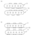
- FIG. 7A shows a fourth form of the fuel cell bundle.
- the adjacent first fuel cell stack 3 and second fuel cell stack 3 face each other.
- the fuel cells 13 are arranged so as to be positioned between them.
- the fuel cell stack is schematically illustrated.
- the fuel cell 13 of the first fuel cell stack 3 is formed on the side surface of the second fuel cell stack 3 on the first fuel cell stack 3 side. It arrange
- the first fuel cell stack 3 Since the gap of the second gas flow path 23 between the first fuel cell stack 3 and the second fuel cell stack 3 is substantially the same, the fuel cell 13 formed on the opposite surface of the adjacent fuel cell stack 3 has Air can be supplied to substantially the same level, the power generation performance between the plurality of fuel cells 13 in the fuel cell stack 3 can be made uniform, and the deterioration of some of the fuel cells 13 can be reduced.
- the fuel cell 13 of the first fuel cell stack 3 and the fuel cell 13 of the second fuel cell stack 3 are connected to the first and second fuels.
- the first fuel battery cell stack 3 and the second fuel cell stack 3 are opposed to each other at a portion where the fuel cell 13 is not formed in the second gas flow path 23, and this portion is a wide gap.
- the fuel cells 13 facing each other are heated by reaction heat, and the power generation performance can be improved.
- the cell connecting member 15 has a shape reflecting the shape of the outer surface of the fuel cell 13, and a difference in height is clearly generated between the portion where the fuel cell 13 is formed and the portion where the fuel cell 13 is not formed.
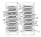
- FIG. 8 shows a form of a fuel cell module having two fuel cell bundles.
- two fuel cell bundles shown in FIG. 4 are arranged in a storage container.
- description of a storage container is abbreviate
- the two fuel cell bundles 4 are juxtaposed so that the connecting member 21 is on the inner side.
- the two fuel cell bundles 4 are juxtaposed so that the arrangement direction of the fuel cell stacks 3 is parallel, and in each fuel cell bundle 4, the connection member 21 is located on the inner side, and the second The gas flow path regulating member 22 is located outside.
- the fuel cell stack 3 includes a side having the cell connecting member 15 formed from one side surface (lower surface) of the fuel cell stack 3 to the other side surface (upper surface) and a side not having the cell connection member 15. 8, the cell connecting member for connecting the fuel cell 13 on the front and back surfaces to the right side of the fuel cell stack 3 in the right fuel cell bundle 4 and to the left side of the fuel cell stack 3 in the left fuel cell bundle 4. 15 is formed.
- the cell connecting member 15 that connects the front and back cells has a long length and thus generates a large amount of heat.
- the fuel cell 13 on the front and back surfaces is disposed outside the two fuel cell bundles juxtaposed. Since the cell connecting member 15 for connecting the two is positioned, the temperature distribution in the storage container can be reduced.
- Fuel gas tank 3 Fuel cell stack 4, 4 'Fuel cell bundle 11 Support 12 First gas flow path 13, 13A, 13B, 13C, 13D Fuel cell 14 Interconnector 15 Cell connecting member 16 Cell stack connecting member 17 Fuel Electrode 18 Air electrode 19 Solid electrolyte 21 Connection member 22 Second gas flow path regulating member 23 Second gas flow path 25 Spacer
Landscapes
- Life Sciences & Earth Sciences (AREA)
- Engineering & Computer Science (AREA)
- Manufacturing & Machinery (AREA)
- Sustainable Development (AREA)
- Sustainable Energy (AREA)
- Chemical & Material Sciences (AREA)
- Chemical Kinetics & Catalysis (AREA)
- Electrochemistry (AREA)
- General Chemical & Material Sciences (AREA)
- Fuel Cell (AREA)
Abstract
Description
のセラミックスで形成されている。ここで、固溶させる希土類元素又はその酸化物としては、Sc、Y、La、Ce、Pr、Nd、Pm、Sm、Eu、Gd、Tb、Dy、Ho、Er、Tm、Yb、Luなど、又は、これらの酸化物などが挙げられる。Y、Yb、又は、これらの酸化物を用いることで原料コストの低減ができる。
3 燃料電池セルスタック
4、4′ 燃料電池バンドル
11 支持体
12 第1ガス流路
13,13A,13B,13C,13D 燃料電池セル
14 インターコネクタ
15 セル接続部材
16 セルスタック接続部材
17 燃料極
18 空気極
19 固体電解質
21 接続部材
22 第2ガス流路規制部材
23 第2ガス流路
25 スペーサ
Claims (11)
- 第1の方向に延びる柱状の複数の燃料電池セルスタックを、該燃料電池セルスタックの側面同士が対向するように間隔をあけて配列してなり、
前記燃料電池セルスタックは、前記第1の方向に沿って第1ガス流路を有しており、かつ、前記第1の方向と交差する第2の方向に並んで配置されるとともに直列接続される複数の燃料電池セルを有しており、
隣接する前記燃料電池セルスタック間に、前記隣接する燃料電池セルスタックの燃料電池セル同士を電気的に接続する接続部材と、該接続部材との間に前記第1ガス流路に沿った第2ガス流路を形成するための第2ガス流路規制部材とを備えてなることを特徴とする燃料電池バンドル。 - 前記第2ガス流路規制部材は絶縁性を有することを特徴とする請求項1に記載の燃料電池バンドル。
- 前記接続部材が、前記第1の方向に分割された複数の部材からなることを特徴とする請求項1または2に記載の燃料電池バンドル。
- 前記接続部材が、前記第1の方向に沿って設けられた一つの部材からなることを特徴とする請求項1または2に記載の燃料電池バンドル。
- 前記第2ガス流路規制部材が、前記第1の方向に分割された複数の部材からなることを特徴とする請求項1乃至4のうちいずれかに記載の燃料電池バンドル。
- 前記第2ガス流路規制部材が、前記第1の方向に沿って設けられた一つの部材からなることを特徴とする請求項1乃至4のうちいずれかに記載の燃料電池バンドル。
- 前記第2ガス流路規制部材および前記接続部材が、前記燃料電池セルスタックの最も側方に配置された前記燃料電池セルよりも外方に設けられていることを特徴とする請求項1乃至6のうちいずれかに記載の燃料電池バンドル。
- 隣接する前記燃料電池セルスタック間であって、前記接続部材と前記第2ガス流路規制部材との間に、スペーサを設けてなることを特徴とする請求項1乃至7のうちいずれかに記載の燃料電池バンドル。
- 隣接する前記燃料電池セルスタックにおいて、第1の前記燃料電池セルスタックの前記燃料電池セルは、第2の前記燃料電池セルスタックの前記第1の燃料電池セルスタック側の側面に形成された燃料電池セル間に位置するように配置されていることを特徴とする請求項1乃至8のうちいずれかに記載の燃料電池バンドル。
- 請求項1乃至9のうちいずれかに記載の燃料電池バンドルを、収納容器内に収納してなることを特徴とする燃料電池モジュール。
- 前記収納容器内に、接続部材が内側となるように前記燃料電池バンドルを2個並置してなることを特徴とする請求項12に記載の燃料電池モジュール。
Priority Applications (4)
| Application Number | Priority Date | Filing Date | Title |
|---|---|---|---|
| JP2012526603A JP5653435B2 (ja) | 2010-07-29 | 2011-07-29 | 燃料電池バンドルおよびこれを備えた燃料電池モジュール |
| CN201180034351.9A CN102986076B (zh) | 2010-07-29 | 2011-07-29 | 燃料电池包及具备该燃料电池包的燃料电池模块 |
| US13/812,837 US9160027B2 (en) | 2010-07-29 | 2011-07-29 | Fuel cell bundle and fuel cell module comprising same |
| EP11812640.8A EP2600456B1 (en) | 2010-07-29 | 2011-07-29 | Fuel cell bundle and fuel cell module provided with same |
Applications Claiming Priority (2)
| Application Number | Priority Date | Filing Date | Title |
|---|---|---|---|
| JP2010170741 | 2010-07-29 | ||
| JP2010-170741 | 2010-07-29 |
Publications (1)
| Publication Number | Publication Date |
|---|---|
| WO2012015051A1 true WO2012015051A1 (ja) | 2012-02-02 |
Family
ID=45530249
Family Applications (1)
| Application Number | Title | Priority Date | Filing Date |
|---|---|---|---|
| PCT/JP2011/067541 Ceased WO2012015051A1 (ja) | 2010-07-29 | 2011-07-29 | 燃料電池バンドルおよびこれを備えた燃料電池モジュール |
Country Status (5)
| Country | Link |
|---|---|
| US (1) | US9160027B2 (ja) |
| EP (1) | EP2600456B1 (ja) |
| JP (1) | JP5653435B2 (ja) |
| CN (1) | CN102986076B (ja) |
| WO (1) | WO2012015051A1 (ja) |
Cited By (5)
| Publication number | Priority date | Publication date | Assignee | Title |
|---|---|---|---|---|
| JP2014192123A (ja) * | 2013-03-28 | 2014-10-06 | Toto Ltd | 固体酸化物型燃料電池装置 |
| WO2020022489A1 (ja) * | 2018-07-27 | 2020-01-30 | 京セラ株式会社 | 燃料電池セル及びセルスタック装置 |
| JPWO2023190754A1 (ja) * | 2022-03-31 | 2023-10-05 | ||
| JPWO2024116970A1 (ja) * | 2022-11-30 | 2024-06-06 | ||
| JPWO2024116971A1 (ja) * | 2022-11-30 | 2024-06-06 |
Families Citing this family (6)
| Publication number | Priority date | Publication date | Assignee | Title |
|---|---|---|---|---|
| WO2015118208A1 (en) * | 2014-02-05 | 2015-08-13 | Elcogen Oy | Assembly method and arrangement for a cell system |
| WO2017038893A1 (ja) * | 2015-08-31 | 2017-03-09 | 京セラ株式会社 | 燃料電池モジュールおよび燃料電池装置 |
| US20190157702A1 (en) * | 2017-11-17 | 2019-05-23 | Lg Fuel Cell Systems, Inc. | Fuel cell secondary interconnect |
| US20190157705A1 (en) * | 2017-11-17 | 2019-05-23 | Lg Fuel Cell Systems, Inc. | Multiple fuel cell secondary interconnect bonding pads and wires |
| US10680270B2 (en) * | 2017-11-17 | 2020-06-09 | Lg Electronics, Inc. | Fuel cell ink trace interconnect |
| CN107978774A (zh) * | 2017-12-07 | 2018-05-01 | 成都因纳维特科技有限公司 | 新能源汽车驱动氢燃料电池包 |
Citations (9)
| Publication number | Priority date | Publication date | Assignee | Title |
|---|---|---|---|---|
| JPH01170954U (ja) * | 1988-05-23 | 1989-12-04 | ||
| JP2003282127A (ja) * | 2002-03-22 | 2003-10-03 | Kyocera Corp | セルスタック及び燃料電池 |
| JP2004281094A (ja) * | 2003-03-12 | 2004-10-07 | Kyocera Corp | セルスタック及び燃料電池 |
| JP2006236625A (ja) * | 2005-02-22 | 2006-09-07 | Kyocera Corp | 燃料電池セル及びこれを用いた燃料電池セルスタック、燃料電池 |
| JP2007035498A (ja) * | 2005-07-28 | 2007-02-08 | Kyocera Corp | 燃料電池セルスタックにおける集電構造 |
| JP2007128739A (ja) * | 2005-11-04 | 2007-05-24 | Hitachi Ltd | 燃料電池 |
| JP2007134230A (ja) | 2005-11-11 | 2007-05-31 | Kyocera Corp | 燃料電池セル、燃料電池セルスタック及び燃料電池 |
| JP2007149510A (ja) * | 2005-11-28 | 2007-06-14 | Kyocera Corp | セルスタック及び燃料電池 |
| JP2007173115A (ja) * | 2005-12-22 | 2007-07-05 | Kyocera Corp | セルスタック及び燃料電池 |
Family Cites Families (3)
| Publication number | Priority date | Publication date | Assignee | Title |
|---|---|---|---|---|
| JPH01170954A (ja) | 1987-12-25 | 1989-07-06 | Matsushita Graphic Commun Syst Inc | 静電記録装置 |
| JP5257826B2 (ja) * | 2007-06-22 | 2013-08-07 | Toto株式会社 | 燃料電池セルスタック、燃料電池セルスタックユニット及び燃料電池 |
| WO2009016857A1 (ja) * | 2007-07-27 | 2009-02-05 | Kyocera Corporation | 燃料電池モジュールおよびそれを具備する燃料電池装置 |
-
2011
- 2011-07-29 CN CN201180034351.9A patent/CN102986076B/zh not_active Expired - Fee Related
- 2011-07-29 EP EP11812640.8A patent/EP2600456B1/en not_active Not-in-force
- 2011-07-29 JP JP2012526603A patent/JP5653435B2/ja not_active Expired - Fee Related
- 2011-07-29 WO PCT/JP2011/067541 patent/WO2012015051A1/ja not_active Ceased
- 2011-07-29 US US13/812,837 patent/US9160027B2/en active Active
Patent Citations (9)
| Publication number | Priority date | Publication date | Assignee | Title |
|---|---|---|---|---|
| JPH01170954U (ja) * | 1988-05-23 | 1989-12-04 | ||
| JP2003282127A (ja) * | 2002-03-22 | 2003-10-03 | Kyocera Corp | セルスタック及び燃料電池 |
| JP2004281094A (ja) * | 2003-03-12 | 2004-10-07 | Kyocera Corp | セルスタック及び燃料電池 |
| JP2006236625A (ja) * | 2005-02-22 | 2006-09-07 | Kyocera Corp | 燃料電池セル及びこれを用いた燃料電池セルスタック、燃料電池 |
| JP2007035498A (ja) * | 2005-07-28 | 2007-02-08 | Kyocera Corp | 燃料電池セルスタックにおける集電構造 |
| JP2007128739A (ja) * | 2005-11-04 | 2007-05-24 | Hitachi Ltd | 燃料電池 |
| JP2007134230A (ja) | 2005-11-11 | 2007-05-31 | Kyocera Corp | 燃料電池セル、燃料電池セルスタック及び燃料電池 |
| JP2007149510A (ja) * | 2005-11-28 | 2007-06-14 | Kyocera Corp | セルスタック及び燃料電池 |
| JP2007173115A (ja) * | 2005-12-22 | 2007-07-05 | Kyocera Corp | セルスタック及び燃料電池 |
Non-Patent Citations (1)
| Title |
|---|
| See also references of EP2600456A4 * |
Cited By (12)
| Publication number | Priority date | Publication date | Assignee | Title |
|---|---|---|---|---|
| JP2014192123A (ja) * | 2013-03-28 | 2014-10-06 | Toto Ltd | 固体酸化物型燃料電池装置 |
| WO2020022489A1 (ja) * | 2018-07-27 | 2020-01-30 | 京セラ株式会社 | 燃料電池セル及びセルスタック装置 |
| JPWO2020022489A1 (ja) * | 2018-07-27 | 2021-08-02 | 京セラ株式会社 | 燃料電池セル及びセルスタック装置 |
| JP7019817B2 (ja) | 2018-07-27 | 2022-02-15 | 京セラ株式会社 | 燃料電池セル及びセルスタック装置 |
| JP2022051823A (ja) * | 2018-07-27 | 2022-04-01 | 京セラ株式会社 | セル及びセルスタック装置 |
| JP7256309B2 (ja) | 2018-07-27 | 2023-04-11 | 京セラ株式会社 | セル及びセルスタック装置 |
| JPWO2023190754A1 (ja) * | 2022-03-31 | 2023-10-05 | ||
| JP7714781B2 (ja) | 2022-03-31 | 2025-07-29 | 京セラ株式会社 | 電気化学セル、電気化学セル装置、モジュールおよびモジュール収容装置 |
| JPWO2024116970A1 (ja) * | 2022-11-30 | 2024-06-06 | ||
| JPWO2024116971A1 (ja) * | 2022-11-30 | 2024-06-06 | ||
| JP7819361B2 (ja) | 2022-11-30 | 2026-02-24 | 日本碍子株式会社 | 電気化学セル及びセパレータ付き電気化学セル |
| JP7819362B2 (ja) | 2022-11-30 | 2026-02-24 | 日本碍子株式会社 | 電気化学セル及びセパレータ付き電気化学セル |
Also Published As
| Publication number | Publication date |
|---|---|
| JPWO2012015051A1 (ja) | 2013-09-12 |
| EP2600456A1 (en) | 2013-06-05 |
| CN102986076B (zh) | 2015-11-25 |
| JP5653435B2 (ja) | 2015-01-14 |
| EP2600456A4 (en) | 2014-08-20 |
| US9160027B2 (en) | 2015-10-13 |
| US20130122387A1 (en) | 2013-05-16 |
| EP2600456B1 (en) | 2016-11-30 |
| CN102986076A (zh) | 2013-03-20 |
Similar Documents
| Publication | Publication Date | Title |
|---|---|---|
| JP5653435B2 (ja) | 燃料電池バンドルおよびこれを備えた燃料電池モジュール | |
| JP5175527B2 (ja) | セルスタック及び燃料電池 | |
| JP5132878B2 (ja) | 燃料電池セル、燃料電池セルスタック及び燃料電池 | |
| JP2012038701A (ja) | 燃料電池の構造体 | |
| JP4741815B2 (ja) | セルスタック及び燃料電池 | |
| JP5192723B2 (ja) | 横縞型燃料電池セル及び燃料電池 | |
| JP5175461B2 (ja) | 横縞型燃料電池セル及び燃料電池 | |
| JP5883028B2 (ja) | セルスタック装置の作製方法 | |
| JP5417543B1 (ja) | 横縞型燃料電池セル | |
| JP5377271B2 (ja) | セルスタック装置、燃料電池モジュールおよび燃料電池装置 | |
| JP5738075B2 (ja) | 固体酸化物形燃料電池セル | |
| JP5437152B2 (ja) | 横縞型固体酸化物形燃料電池セルスタックおよび燃料電池 | |
| JP5480656B2 (ja) | 横縞型固体酸化物形燃料電池バンドルおよび燃料電池 | |
| JP2012038696A (ja) | 燃料電池の構造体 | |
| JP5449076B2 (ja) | 燃料電池セル | |
| JP5352285B2 (ja) | 横縞型固体酸化物形燃料電池セルスタックおよび燃料電池 | |
| JP2013157190A (ja) | 固体酸化物形燃料電池セル、セルスタック装置および燃料電池モジュールならびに燃料電池装置 | |
| JP5132879B2 (ja) | 横縞型燃料電池セルおよび燃料電池 | |
| JP5179153B2 (ja) | 横縞型燃料電池セルおよびセルスタック並びに燃料電池 | |
| JP7433450B2 (ja) | セル、セルスタック装置、モジュールおよびモジュール収容装置 | |
| JP5036163B2 (ja) | 燃料電池セル及びセルスタック並びに燃料電池 | |
| JP5417551B2 (ja) | 燃料電池の構造体 | |
| JP3174601U (ja) | 積層型固体酸化物形燃料電池のリード線接続構造 | |
| JP6059038B2 (ja) | セルスタック装置、燃料電池モジュールおよび燃料電池装置 |
Legal Events
| Date | Code | Title | Description |
|---|---|---|---|
| WWE | Wipo information: entry into national phase |
Ref document number: 201180034351.9 Country of ref document: CN |
|
| 121 | Ep: the epo has been informed by wipo that ep was designated in this application |
Ref document number: 11812640 Country of ref document: EP Kind code of ref document: A1 |
|
| WWE | Wipo information: entry into national phase |
Ref document number: 2012526603 Country of ref document: JP |
|
| WWE | Wipo information: entry into national phase |
Ref document number: 13812837 Country of ref document: US |
|
| NENP | Non-entry into the national phase |
Ref country code: DE |
|
| REEP | Request for entry into the european phase |
Ref document number: 2011812640 Country of ref document: EP |
|
| WWE | Wipo information: entry into national phase |
Ref document number: 2011812640 Country of ref document: EP |