WO2012015252A2 - 무선 통신 시스템에서 프리코딩된 신호 송수신 방법 및 장치 - Google Patents
무선 통신 시스템에서 프리코딩된 신호 송수신 방법 및 장치 Download PDFInfo
- Publication number
- WO2012015252A2 WO2012015252A2 PCT/KR2011/005561 KR2011005561W WO2012015252A2 WO 2012015252 A2 WO2012015252 A2 WO 2012015252A2 KR 2011005561 W KR2011005561 W KR 2011005561W WO 2012015252 A2 WO2012015252 A2 WO 2012015252A2
- Authority
- WO
- WIPO (PCT)
- Prior art keywords
- matrix
- codebook
- precoding
- size
- precoding matrices
- Prior art date
- Legal status (The legal status is an assumption and is not a legal conclusion. Google has not performed a legal analysis and makes no representation as to the accuracy of the status listed.)
- Ceased
Links
Classifications
-
- H—ELECTRICITY
- H04—ELECTRIC COMMUNICATION TECHNIQUE
- H04L—TRANSMISSION OF DIGITAL INFORMATION, e.g. TELEGRAPHIC COMMUNICATION
- H04L25/00—Baseband systems
- H04L25/02—Details ; arrangements for supplying electrical power along data transmission lines
- H04L25/03—Shaping networks in transmitter or receiver, e.g. adaptive shaping networks
- H04L25/03891—Spatial equalizers
- H04L25/03898—Spatial equalizers codebook-based design
- H04L25/0391—Spatial equalizers codebook-based design construction details of matrices
-
- H—ELECTRICITY
- H04—ELECTRIC COMMUNICATION TECHNIQUE
- H04B—TRANSMISSION
- H04B7/00—Radio transmission systems, i.e. using radiation field
- H04B7/02—Diversity systems; Multi-antenna system, i.e. transmission or reception using multiple antennas
- H04B7/04—Diversity systems; Multi-antenna system, i.e. transmission or reception using multiple antennas using two or more spaced independent antennas
- H04B7/0413—MIMO systems
- H04B7/0456—Selection of precoding matrices or codebooks, e.g. using matrices antenna weighting
- H04B7/046—Selection of precoding matrices or codebooks, e.g. using matrices antenna weighting taking physical layer constraints into account
- H04B7/0473—Selection of precoding matrices or codebooks, e.g. using matrices antenna weighting taking physical layer constraints into account taking constraints in layer or codeword to antenna mapping into account
-
- H—ELECTRICITY
- H04—ELECTRIC COMMUNICATION TECHNIQUE
- H04B—TRANSMISSION
- H04B7/00—Radio transmission systems, i.e. using radiation field
- H04B7/02—Diversity systems; Multi-antenna system, i.e. transmission or reception using multiple antennas
- H04B7/04—Diversity systems; Multi-antenna system, i.e. transmission or reception using multiple antennas using two or more spaced independent antennas
- H04B7/0413—MIMO systems
- H04B7/0456—Selection of precoding matrices or codebooks, e.g. using matrices antenna weighting
-
- H—ELECTRICITY
- H04—ELECTRIC COMMUNICATION TECHNIQUE
- H04B—TRANSMISSION
- H04B7/00—Radio transmission systems, i.e. using radiation field
- H04B7/02—Diversity systems; Multi-antenna system, i.e. transmission or reception using multiple antennas
- H04B7/04—Diversity systems; Multi-antenna system, i.e. transmission or reception using multiple antennas using two or more spaced independent antennas
- H04B7/0413—MIMO systems
- H04B7/0452—Multi-user MIMO systems
-
- H—ELECTRICITY
- H04—ELECTRIC COMMUNICATION TECHNIQUE
- H04B—TRANSMISSION
- H04B7/00—Radio transmission systems, i.e. using radiation field
- H04B7/02—Diversity systems; Multi-antenna system, i.e. transmission or reception using multiple antennas
- H04B7/04—Diversity systems; Multi-antenna system, i.e. transmission or reception using multiple antennas using two or more spaced independent antennas
- H04B7/0413—MIMO systems
- H04B7/0456—Selection of precoding matrices or codebooks, e.g. using matrices antenna weighting
- H04B7/046—Selection of precoding matrices or codebooks, e.g. using matrices antenna weighting taking physical layer constraints into account
- H04B7/0469—Selection of precoding matrices or codebooks, e.g. using matrices antenna weighting taking physical layer constraints into account taking special antenna structures, e.g. cross polarized antennas into account
-
- H—ELECTRICITY
- H04—ELECTRIC COMMUNICATION TECHNIQUE
- H04B—TRANSMISSION
- H04B7/00—Radio transmission systems, i.e. using radiation field
- H04B7/02—Diversity systems; Multi-antenna system, i.e. transmission or reception using multiple antennas
- H04B7/04—Diversity systems; Multi-antenna system, i.e. transmission or reception using multiple antennas using two or more spaced independent antennas
- H04B7/0413—MIMO systems
- H04B7/0456—Selection of precoding matrices or codebooks, e.g. using matrices antenna weighting
- H04B7/0478—Special codebook structures directed to feedback optimisation
-
- H—ELECTRICITY
- H04—ELECTRIC COMMUNICATION TECHNIQUE
- H04B—TRANSMISSION
- H04B7/00—Radio transmission systems, i.e. using radiation field
- H04B7/02—Diversity systems; Multi-antenna system, i.e. transmission or reception using multiple antennas
- H04B7/04—Diversity systems; Multi-antenna system, i.e. transmission or reception using multiple antennas using two or more spaced independent antennas
- H04B7/06—Diversity systems; Multi-antenna system, i.e. transmission or reception using multiple antennas using two or more spaced independent antennas at the transmitting station
- H04B7/0613—Diversity systems; Multi-antenna system, i.e. transmission or reception using multiple antennas using two or more spaced independent antennas at the transmitting station using simultaneous transmission
- H04B7/0615—Diversity systems; Multi-antenna system, i.e. transmission or reception using multiple antennas using two or more spaced independent antennas at the transmitting station using simultaneous transmission of weighted versions of same signal
- H04B7/0619—Diversity systems; Multi-antenna system, i.e. transmission or reception using multiple antennas using two or more spaced independent antennas at the transmitting station using simultaneous transmission of weighted versions of same signal using feedback from receiving side
- H04B7/0636—Feedback format
- H04B7/0639—Using selective indices, e.g. of a codebook, e.g. pre-distortion matrix index [PMI] or for beam selection
-
- H—ELECTRICITY
- H04—ELECTRIC COMMUNICATION TECHNIQUE
- H04B—TRANSMISSION
- H04B7/00—Radio transmission systems, i.e. using radiation field
- H04B7/02—Diversity systems; Multi-antenna system, i.e. transmission or reception using multiple antennas
- H04B7/04—Diversity systems; Multi-antenna system, i.e. transmission or reception using multiple antennas using two or more spaced independent antennas
- H04B7/06—Diversity systems; Multi-antenna system, i.e. transmission or reception using multiple antennas using two or more spaced independent antennas at the transmitting station
- H04B7/0613—Diversity systems; Multi-antenna system, i.e. transmission or reception using multiple antennas using two or more spaced independent antennas at the transmitting station using simultaneous transmission
- H04B7/0615—Diversity systems; Multi-antenna system, i.e. transmission or reception using multiple antennas using two or more spaced independent antennas at the transmitting station using simultaneous transmission of weighted versions of same signal
- H04B7/0619—Diversity systems; Multi-antenna system, i.e. transmission or reception using multiple antennas using two or more spaced independent antennas at the transmitting station using simultaneous transmission of weighted versions of same signal using feedback from receiving side
- H04B7/0636—Feedback format
- H04B7/0645—Variable feedback
- H04B7/065—Variable contents, e.g. long-term or short-short
-
- H—ELECTRICITY
- H04—ELECTRIC COMMUNICATION TECHNIQUE
- H04L—TRANSMISSION OF DIGITAL INFORMATION, e.g. TELEGRAPHIC COMMUNICATION
- H04L1/00—Arrangements for detecting or preventing errors in the information received
- H04L1/0001—Systems modifying transmission characteristics according to link quality, e.g. power backoff
- H04L1/0023—Systems modifying transmission characteristics according to link quality, e.g. power backoff characterised by the signalling
- H04L1/0026—Transmission of channel quality indication
-
- H—ELECTRICITY
- H04—ELECTRIC COMMUNICATION TECHNIQUE
- H04L—TRANSMISSION OF DIGITAL INFORMATION, e.g. TELEGRAPHIC COMMUNICATION
- H04L1/00—Arrangements for detecting or preventing errors in the information received
- H04L1/0001—Systems modifying transmission characteristics according to link quality, e.g. power backoff
- H04L1/0023—Systems modifying transmission characteristics according to link quality, e.g. power backoff characterised by the signalling
- H04L1/0028—Formatting
- H04L1/0031—Multiple signaling transmission
-
- H—ELECTRICITY
- H04—ELECTRIC COMMUNICATION TECHNIQUE
- H04L—TRANSMISSION OF DIGITAL INFORMATION, e.g. TELEGRAPHIC COMMUNICATION
- H04L25/00—Baseband systems
- H04L25/02—Details ; arrangements for supplying electrical power along data transmission lines
- H04L25/03—Shaping networks in transmitter or receiver, e.g. adaptive shaping networks
- H04L25/03891—Spatial equalizers
- H04L25/03898—Spatial equalizers codebook-based design
- H04L25/03929—Spatial equalizers codebook-based design with layer mapping, e.g. codeword-to layer design
-
- H—ELECTRICITY
- H04—ELECTRIC COMMUNICATION TECHNIQUE
- H04B—TRANSMISSION
- H04B7/00—Radio transmission systems, i.e. using radiation field
- H04B7/02—Diversity systems; Multi-antenna system, i.e. transmission or reception using multiple antennas
- H04B7/04—Diversity systems; Multi-antenna system, i.e. transmission or reception using multiple antennas using two or more spaced independent antennas
- H04B7/0413—MIMO systems
- H04B7/0456—Selection of precoding matrices or codebooks, e.g. using matrices antenna weighting
- H04B7/046—Selection of precoding matrices or codebooks, e.g. using matrices antenna weighting taking physical layer constraints into account
- H04B7/0465—Selection of precoding matrices or codebooks, e.g. using matrices antenna weighting taking physical layer constraints into account taking power constraints at power amplifier or emission constraints, e.g. constant modulus, into account
-
- H—ELECTRICITY
- H04—ELECTRIC COMMUNICATION TECHNIQUE
- H04B—TRANSMISSION
- H04B7/00—Radio transmission systems, i.e. using radiation field
- H04B7/02—Diversity systems; Multi-antenna system, i.e. transmission or reception using multiple antennas
- H04B7/10—Polarisation diversity; Directional diversity
-
- H—ELECTRICITY
- H04—ELECTRIC COMMUNICATION TECHNIQUE
- H04L—TRANSMISSION OF DIGITAL INFORMATION, e.g. TELEGRAPHIC COMMUNICATION
- H04L5/00—Arrangements affording multiple use of the transmission path
- H04L5/0001—Arrangements for dividing the transmission path
- H04L5/0003—Two-dimensional division
- H04L5/0005—Time-frequency
- H04L5/0007—Time-frequency the frequencies being orthogonal, e.g. OFDM(A) or DMT
-
- H—ELECTRICITY
- H04—ELECTRIC COMMUNICATION TECHNIQUE
- H04L—TRANSMISSION OF DIGITAL INFORMATION, e.g. TELEGRAPHIC COMMUNICATION
- H04L5/00—Arrangements affording multiple use of the transmission path
- H04L5/0001—Arrangements for dividing the transmission path
- H04L5/0014—Three-dimensional division
- H04L5/0023—Time-frequency-space
-
- H—ELECTRICITY
- H04—ELECTRIC COMMUNICATION TECHNIQUE
- H04L—TRANSMISSION OF DIGITAL INFORMATION, e.g. TELEGRAPHIC COMMUNICATION
- H04L5/00—Arrangements affording multiple use of the transmission path
- H04L5/003—Arrangements for allocating sub-channels of the transmission path
- H04L5/0053—Allocation of signalling, i.e. of overhead other than pilot signals
Definitions
- the following description relates to a wireless communication system, and more particularly, to a method and apparatus for transmitting and receiving a precoded signal.
- Multi-Input Multi-Output is a technology that improves the transmission and reception efficiency of data by using multiple transmission antennas and multiple reception antennas, instead of using one transmission antenna and one reception antenna. If a single antenna is used, the receiving side receives data through a single antenna path, but if multiple antennas are used, the receiving end receives data through multiple paths. Therefore, the data transmission speed and the transmission amount can be improved, and the coverage can be increased.
- a receiver eg, a terminal feeds back to a transmitter (eg, a base station), a rank indicator (RI), a precoding matrix index (PMI), Channel Quality Information (CQI) and the like are defined.
- the feedback information may be collectively referred to as channel state information (CSI).
- the terminal may feed back the PMI and RI preferred by the terminal to the base station based on the measurement result for the channel from the base station.
- the RI preferred by the UE corresponds to a downlink transmission tank value that may have the highest data rate if used by the base station in a given channel state.
- the PMI preferred by the terminal is an index indicating a precoding matrix suitable for the channel state measured by the terminal in a codebook, which is a set of precoding matrix candidates, and a codebook that is predetermined and shared between the base station and the terminal is used.
- the CQI is calculated based on the PMI / RI reported by the UE and corresponds to a modulation and coding scheme (MCS) level applied to downlink transmission.
- MCS modulation and coding scheme
- the CQI may indicate an MCS level that provides an acceptable packet error rate when precoder information and rank values according to PMI / RI reported by the UE are used.
- the channel state is more than that of the communication according to the single user-MIM0 (SU-MIMO) scheme.
- PMI feedback based on a predetermined codebook
- the precoding information is obtained using a hierarchical codebook that determines one final precoding matrix W from two different attribute precoding information representing the channel state (for example, W1 and W2). Can represent.
- the first precoding matrix indicator (PMI) is indicated ( determine a first matrix W1 from a first codebook comprising precoding matrices indicating, and determine a second matrix W2 from a second codebook containing all the precoding matrices indicated by the second PMI, Determining a precoding matrix (W) based on the first matrix (W1) and the second matrix (W2); Performing precoding using the determined precoding matrix (W) on at least one layer to which a signal to be transmitted is mapped; And the precoded And transmitting the signal to a receiver.
- PMI precoding matrix indicator
- each of the precoding matrices included in the first codebook may be configured as a block diagonal matrix, and the blocks of the block diagonal matrix may be configured to be independent of each other.
- each of the precoding matrices included in the second codebook may include an upper element and a lower element, and the lower element may include a phase rotation value.
- a method for receiving a signal pre-coded by a receiver includes at least one layer to which a signal transmitted by a transmitter is mapped. Receiving a precoded signal from the transmitter, on which precoding has been performed; And a precoding matrix indicated by a first matrix W1 and a second PMI determined from a first codebook including precoding matrices indicated by a first precoding matrix indicator (PMI) for the precoded signal. And processing using the precoding matrix W determined based on the second matrix W2 determined from the second codebook comprising the following.
- each of the precoding matrices included in the first codebook may be configured as a block diagonal matrix, and the blocks of the block diagonal matrix may be configured to be independent of each other.
- each of the precoding matrices included in the second codebook may include an upper element and a lower element, and the lower element may include a phase rotation value.
- a transmitter for transmitting a precoded signal in a wireless communication system supporting multiple antenna transmission the transmission module for transmitting a signal to the receiver; Receiving modules for receiving a signal from the receiver; And a processor controlling the transmitter including the transmission modules and the reception modules.
- the processor determines the first matrix W1 from the first codebook including the precoding matrices indicated by the first precoding matrix indicator (PMI), and the precoding matrices indicating the second PMI.
- PMI precoding matrix indicator
- each of the precoding matrices included in the first codebook may be configured as a block diagonal matrix, and the blocks of the block diagonal matrix may be configured to be independent of each other.
- each of the precoding matrices included in the second codebook may include an upper element and a lower element, and the lower element may include a phase rotation value.
- a receiver for receiving a precoded signal in a wireless communication system supporting multiple antenna transmission a transmission module for transmitting a signal to the transmitter; Reception modules for receiving a signal from the transmitter; A processor may be configured to control the receiver including the transmission modules and the reception modules. Wherein the processor is further configured to receive a precoded signal from the transmitter via the receiving modules, wherein the precode is performed on at least one layer to which a signal transmitted by the transmitter is mapped; Precoding matrices indicated by a first matrix W1 and a second PMI determined from a first codebook including precoding matrices indicated by a first precoding matrix indicator (PMI).
- PMI precoding matrix indicator
- each of the precoding matrices included in the first codebook may be configured as a block diagonal matrix, and the blocks of the block diagonal matrix may be configured to be independent of each other.
- Each of the precoding matrices included in the codebook consists of an upper element and a lower element, and the lower element may include a phase rotation value.
- the i th precoding matrix W1 (i) among the precoding matrices included in the first codebook and the j th precoding matrix W2 (j) among the precoding matrices included in the second codebook are Is defined as a mathematical expression
- Wl (i) is defined as a block diagonal matrix of size Ntx2M, i and Y / correspond to each block of the block diagonal matrix, each of and is a matrix of size (Nt / 2) XM, and Nt is the above Is the number of transmit antennas of the transmitter
- W2 (j) is defined as a matrix of size 2MXr, r is the number of layers
- (; ⁇ , /, ...,) is a vector of size Mxl and ⁇ vectors of P-component of the component is 1 and the remaining components are 0, e , ee corresponds to the upper element, , ...
- Y j ⁇ M corresponds to the sub-element,
- ⁇ ] Yj corresponds to the phase rotation value
- l ⁇ k, 1, / 7 ⁇ M, k '/, ⁇ are each integer Can be.
- the i th precoding matrix W1 (i) among the precoding matrices included in the first codebook and the j th precoding matrix W2 (j) among the precoding matrices included in the second codebook are Is defined as a mathematical expression
- Wl (i) is defined as a block diagonal matrix of size Ntx2M, X / corresponds to each block of the block diagonal matrix, X, and. Is a matrix of size (Nt / 2) XM, Nt is the number of transmit antennas of the transmitter, W2 (j) is defined as a matrix of size 2MXr, and r is the above The number of layers, ⁇ ( , 1, k2, 11, 12, nl,?
- the i th precoding matrix W1 (i) among the precoding matrices included in the first codebook and the j th precoding matrix W2 (j) among the precoding matrices included in the second codebook are Is defined as a mathematical expression
- Wl (i) is defined as a block diagonal matrix of size Ntx2M, i and Y / correspond to each block of the block diagonal matrix, X,. And ⁇ ,.
- Nt / 2 is the number of transmit antennas of the transmitter
- W2 (j) is a size of 2MXr.
- r is the number of layers, M FFkl, kl, 11, 12, nl,
- e M Pj Q M, ...,? e M corresponds to the lower element, Ctj, j , ⁇ corresponds to the phase rotation value, l ⁇ Ji, k2, 11, 12, nl, ⁇ 2 ⁇ , kl, k2, 11, 12, nl, n2 may each be an integer.
- the i th precoding matrix W1 (i) and the j th precoding matrix W2 (j) in the precoding matrices included in the second codebook are Is defined as
- Wl (i) is defined as a block diagonal matrix of size Ntx2M, X / corresponds to each block of the block diagonal matrix, ⁇ ⁇ is a matrix of size (Nt / 2) XM, and Nt is a transmission of the transmitter.
- W2 (j) is defined as a matrix of size 2MXr, r is the number of layers, (i ⁇ k, /, ...,) is a vector of size Mx l and the column of X / (column) are coefficients that make up the linear combination (linear combinat ion) of the vector, ⁇ , ..., and is corresponding to the top element, Ke ⁇ ⁇ ⁇ 1, ..., ⁇ corresponds to the lower element And ci j , P j , and ⁇ ⁇ correspond to the phase rotation value, and ⁇ 1, may each be an integer.
- ⁇ C 2 C 3 C 4 ] r , Cl , C2 , C 3 , C4 is a complex number
- W can be defined as in the following equation.
- a method and apparatus for transmitting and receiving a precoded signal using an efficient hierarchical codebook capable of more accurately reflecting a channel state in a system having an extended antenna configuration can be provided. Effects obtained in the present invention are not limited to the above-mentioned effects, and other effects not mentioned above may be clearly understood by those skilled in the art from the following description. will be.
- FIG. 1 is a diagram illustrating a structure of a type 1 radio frame.
- FIG. 2 is a diagram illustrating a structure of a type 2 wireless frame.
- 3 is an exemplary diagram illustrating an example of a resource grid for one downlink slot.
- FIG. 4 is a diagram illustrating a structure of a downlink subframe.
- 5 is a diagram illustrating a structure of an uplink subframe.
- FIG. 6 is a configuration diagram of a wireless communication system having multiple antennas.
- FIG. 7 is a diagram for describing a codebook based precoding technique.
- 8 and 9 are diagrams illustrating examples of 8Tx cross-polar antenna configurations.
- FIG. 10 is a flowchart illustrating a method of transmitting and receiving a precoded signal according to an example of the present invention.
- FIG. 11 is a diagram showing the configuration of a transmitter apparatus and a receiver apparatus according to the present invention.
- each component or feature may be considered to be optional unless otherwise stated.
- Each component or feature may be embodied in a form that is not combined with other components or features.
- some components and / or features may be combined to form an embodiment of the present invention.
- the order of the operations described in the embodiments of the present invention may be changed. Some configurations or features of one embodiment may be included in another embodiment or may be substituted for components or features of another embodiment.
- the base station communicates directly with the terminal. It has a meaning as a terminal node of a performing network. Certain operations described as performed by the base station in this document may be performed by an upper node of the base station in some cases.
- a base station may be replaced by terms such as a fixed station, a NodeB, an eNodeB (eNB), an access point (AP), and the like.
- the term can be used as a concept including a cell or sector.
- a serving base station may be referred to as a serving cell
- a cooperative base station may also be referred to as a cooperative cell.
- terminal may be replaced with terms such as UE user equipment (MS), Mole le Station (MS), Mole le Subscriber Station (MSS), and Subscriber Station (SS).
- Embodiments of the present invention may be supported by standard documents disclosed in at least one of the wireless access systems IEEE 802 system, 3GPP system, 3GPP LTE and LTE-A (LTE-Advanced) system and 3GPP2 system. That is, the steps or parts which are not described in order to clarify the technical spirit of the present invention may be supported by the above documents. In addition, all terms disclosed in this document may be described by the above standard document.
- CDMA code division multiple access
- FDMA frequency division multiple access
- TDMA time division multiple access
- OFDMA orthogonal frequency division multiple access
- SC to FDMA single carrier frequency division multiple access
- CDMA It may be implemented by a radio technology such as Universal Terrestrial Radio Access (UTRA) or CDMA2000.
- TDMA may be implemented in a wireless technology such as Global System for Mobile Communications (GSM) / General Packet Radio Service (GPRS) / Enhanced Data Rates for GSM Evolut ion (EDGE).
- GSM Global System for Mobile Communications
- GPRS General Packet Radio Service
- EDGE Enhanced Data Rates for GSM Evolut ion
- 0FDMA may be implemented with a radio technology such as IEEE 802.11 (Wi-Fi), IEEE 802.16 (WiMAX), IEEE 802-20, E-UTRAC Evolved UTRA (etc.).
- UTRA is part of the UMTS Jniversal Mobile Telecommuni- cation Systems.
- 3rd Generat ion Partnership Project (3GPP) long term evolut ion (LTE) is part of Evolved UMTS (E-UMTS) using E-UT A, employing 0FDMA in downlink and SC-FDMA in uplink .
- LTE-A Advanced
- LTE-A Advanced
- WiMAX can be described by the IEEE 802.16e standard (WirelessMAN- 0FDMA Reference System) and the advanced IEEE 802.16m standard (WirelessMAN-OFDMA Advanced system).
- IEEE 802.16e WirelessMAN- 0FDMA Reference System
- advanced IEEE 802.16m WirelessMAN-OFDMA Advanced system
- uplink / downlink data packet transmission is performed in subframe units, and one subframe is defined as a predetermined time interval including a plurality of 0FDM symbols.
- the 3GPP LTE standard supports a type 1 radio frame structure applicable to frequency division duplex (FDD) and a type 2 radio frame structure applicable to time division duplex (TDD).
- the downlink radio frame consists of 10 subframes, and one subframe consists of two slots.
- the time taken for one subframe to be transmitted is called a transmission timing interval (TTI).
- TTI transmission timing interval
- one subframe may have a length of 1 ms and one slot may have a length of 0.5 ms.
- One slot includes a plurality of 0FDM symbols in the time domain and includes a plurality of resource blocks (RBs) in the frequency domain.
- the number of 0FDM symbols included in one slot may vary depending on the configuration of the CP (conf igurat ion).
- CP has an extended CP (normal CP) and a normal CP normal CP (CP).
- normal CP normal CP
- CP normal CP
- the number of symbols may be seven.
- the OFDM symbol is configured by an extended CP, since the length of one OFDM symbol is increased, the number of OFDM symbols included in one slot is smaller than that of the normal CP.
- the number of OFDM symbols included in one slot may be six. If the channel state is unstable, such as when the terminal moves at a high speed, an extended CP may be used to further reduce intersymbol interference.
- one subframe includes 14 OFDM symbols.
- the first two or three OFDM symbols of each subframe may be allocated to a PDCClKphysical downlink control channel (PDCC), and the remaining OFDM symbols may be allocated to a physical downlink shared channel (PDSCH).
- PDCC PDCClKphysical downlink control channel
- PDSCH physical downlink shared channel
- the type 2 radio frame consists of two half frames, and each half frame consists of five subframes. Subframes may be classified into a general subframe and a special subframe.
- the special subframe is a subframe including three fields of DwPTSCDownlinkPilot Time Slot (GPW), Gap Period (GP), and UpPTSCUpHnk Pi lot Time Slot (GPW). The length of these three fields can be set individually, but the total length of the three fields must be 1 ms.
- One subframe consists of two slots. That is, one subframe consists of two slots regardless of the radio frame type.
- the structure of the radio frame is only an example, and the number of subframes included in the radio frame or the number of slots included in the subframe and the number of symbols included in the slot may be variously changed.
- the downlink slot includes a plurality of OFDM symbols in the time domain and includes a plurality of resource blocks (RBs) in the frequency domain.
- RBs resource blocks
- one downlink slot includes 7 OFDM symbols and one resource block includes 12 subcarriers (subcarriers) by way of example, but is not limited thereto.
- Each element on the resource grid is called a resource element (RE).
- the resource element a (k, l) becomes a resource element located at the kth subcarrier and the first 0FDM symbol.
- one The RB includes 12X7 resource elements (in the case of an extended CP, it includes 12X6 resource elements). Since the interval of each subcarrier is 15 kHz, one resource block includes about 180 kHz in the frequency domain.
- N D1 ⁇ r The number of resource blocks included in the downlink slot. N DI ⁇ ] may be determined according to a downlink transmission bandwidth set by scheduling of the base station.
- FIG. 4 is a diagram illustrating a structure of a downlink subframe.
- a maximum of three (one, two, or three) OFDM symbols in front of the first slot in one subframe corresponds to a control region to which a control channel is allocated.
- the remaining OFDM symbols correspond to data regions to which a physical downlink shared channel (PDSCH) is allocated.
- the basic unit of transmission is one subframe. That is, PDCCH and PDSCH are allocated over two slots.
- Downlink control channels used in the 3GPP LTE system include, for example, a physical control format indicator channel (PCFICH), a physical downlink control channel (PDCCH), and a physical HARQ indicator channel.
- PCFICH physical control format indicator channel
- PDCCH physical downlink control channel
- PHICH Physical Hybrid automatic repeat request Indicator Channel
- the PCFICH is transmitted in the first OFDM symbol of a subframe and includes information on the number of OFDM symbols used for control channel transmission in the subframe.
- the PHICH includes a HARQ ACK / NAC signal as a response of the uplink transmission.
- Control information transmitted through the PDCCH is referred to as downlink control information (DCI).
- DCI includes uplink or downlink scheduling information or an uplink transmit power control command for a certain terminal group.
- the PDCCH includes a resource allocation and transmission format of a DL shared channel (DL-SCH), resource allocation information of a UL shared channel (UL-SCH), paging information of a paging channel (PCH), system information on a DL-SCH, and a PDSCH.
- Resource allocation of a higher layer control message such as a random access response transmitted to a mobile station, a set of transmit power control commands for individual terminals in a certain terminal group, transmission power control information, activation of VoIPCVoice over IP), and the like. It may include.
- a plurality of PDCCHs may be transmitted in the control region.
- the terminal may monitor the plurality of PDCCHs.
- the PDCCH is transmitted in a combination of one or more consecutive Control Channel Elements (CCEs).
- CCE is a logical allocation unit used to provide a PDCCH at a coding rate based on the state of a radio channel.
- the CCE processes multiple resource element groups.
- the format of the PDCCH The number of available bits is determined according to the correlation between the number of CCEs and the coding rate provided by the CCEs.
- the base station determines the PDCCH format according to the DCI transmitted to the terminal, and adds a cyclic redundancy check (CRC) to the control information.
- CRC cyclic redundancy check
- the CRC is masked with an identifier called Radio Network Temporary Identifier (RNTI) according to the owner or purpose of the PDCCH. If the PDCCH is for a specific terminal, the cell-RNTI (C-RNTI) identifier of the terminal may be masked to the CRC.
- RNTI Radio Network Temporary Identifier
- a paging indicator identifier may be masked to the CRC.
- the PDCCH is for system information (more specifically, system information block (SIB))
- SIB system information block
- RNTKSI-RNTI may be masked to the CRC.
- the random access -RNTKRA-RNTI may be masked to the CRC.
- the uplink subframe may be divided into a control region and a data region in the frequency domain.
- a physical uplink control channel (PUCCH) including uplink control information is allocated to the control region.
- PUSCH physical uplink shared channel
- PUCCH has three main uses: transmitting an ACK / NACK for PDSCH, transmitting a Channel Quality Indicator (CQI) for frequency domain scheduling of PDSCH, and requesting a PUSCH transmission resource (scheduling request). to be.
- the CQI information bit may include one or more fields.
- the CQI field indicating the CQI index for determining the Modulation and Coding Scheme (ICS)
- the PMKPrecoding Matrix Indicator (PMK) field indicating the index of the precoding matrix on the codebook
- the RKRank Indicator (RKR) field indicating the tank
- CQI information May be included in the bit.
- one UE does not simultaneously transmit a PUCCH and a PUSCH.
- PUCCH for one UE is allocated to an RB pair in a subframe.
- Resource blocks belonging to a resource block pair occupy different subcarriers for two slots. This is called that the resource block pair allocated to the PUCCH is frequency-hopped at the slot boundary.
- Multiple Antenna (MIMO) System MIMO
- FIG. 6 is a configuration diagram of a wireless communication system having multiple antennas.
- the number of transmit antennas, as Fig. 6 (a) shown in ⁇ ⁇ open-circuit, receiving, increasing the number of antennas of the open-circuit N R, is in proportion to the number of antennas, unlike in the case only the transmitter or the receiver to use a plurality of antenna theory Channel transmission capacity is increased. Therefore, the transmission rate can be improved and the frequency efficiency can be significantly improved.
- the transmission rate is theoretically the maximum transmission rate with a single antenna. 0) has to be increased by the increase rate became (0 multiplied.
- the research trends related to multi-antennas to date include the study of information theory aspects related to the calculation of multi-antenna communication capacity in various channel environments and multi-access environments, the study of wireless channel measurement and model derivation of multi-antenna systems, improvement of transmission reliability and improvement of transmission rate Research is being actively conducted from various viewpoints, such as research on space-time signal processing technology.
- the communication method in a multi-antenna system will be described in more detail using mathematical modeling. It is assumed that there are n transmit antennas and ⁇ receive antennas in the system.
- the transmission information may be expressed as follows.
- Each transmission information S ⁇ 3S 2f 3S N T may have a different transmission power.
- Each transfer Power , ⁇ ,... ,, The transmission information whose transmission power is adjusted may be expressed as follows.
- the weight matrix W is applied to the information vector s of which the transmission power is adjusted.
- the W transmission information is appropriately distributed to each antenna according to a transmission channel situation.
- "1 ⁇ 2 vector X it can be expressed as follows.
- W is also called a precoding matrix.
- the reception signal of each antenna; ⁇ , ⁇ 2 , "' , :) ⁇ may be expressed as a vector as follows.
- channels may be divided according to transmit and receive antenna indexes.
- the channel from the transmit antenna _ / to the receive antenna / is denoted by. Note that, in ⁇ : /, the order of the index is the receiving antenna index first, and the index of the transmitting antenna is later.
- FIG. 6 (b) shows channels from ⁇ transmit antennas to receive antennas /.
- the channels may be bundled and displayed in the form of a vector and a matrix.
- a channel arriving from a total of ⁇ transmit antennas to a receive antenna / may be represented as follows.
- the real channel is added with Additive White Gaussian Noise (AWGN) after passing through the channel matrix H.
- AWGN Additive White Gaussian Noise
- the white noise «1, « 2 , "' » ⁇ added to each of the N R receiving antennas may be expressed as follows.
- the number of rows and columns of the channel matrix H indicating the channel state is determined by the number of transmitting and receiving antennas.
- the number of rows in the channel matrix H is equal to the number of receiving antennas, and the number of columns is equal to the number of transmitting antennas 7. That is, the channel matrix H is N R X N.
- the rank of a matrix is defined as the minimum number of rows or columns that are independent of each other. Thus, the tank of the matrix cannot be larger than the number of rows or columns.
- the tank (ranA: (H)) of the channel matrix H is limited as follows.
- a tank can be defined as the number of nonzero eigenvalues when the matrix is eigenvalue decomposition.
- another definition of a tank can be defined as the number of nonzero singular values when singular value decomposition. Therefore, the physical meaning of the tank in the channel matrix is the maximum number that can send different information in a given channel.
- 'Rank' for MIM0 transmission refers to the number of paths that can independently transmit signals at specific time points and specific frequency resources, and 'Number of layers' denotes each path. It indicates the number of signal streams transmitted through the system. In general, since the transmitting end transmits a number of layers corresponding to the number of tanks used for signal transmission, unless otherwise specified, a tank has the same meaning as the number of layers.
- the MIM0 method may be divided into an open-loop method and a closed-loop method.
- the open-loop MIM0 scheme means that the transmitter performs MIM0 transmission without feedback of channel state information from the MIM0 receiver.
- Closed-loop MIM0 scheme MIM0 This means that the MIM0 transmission is performed by the transmitter by receiving the channel state information from the receiver.
- each of the transmitter and the receiver may perform beamforming based on channel state information in order to obtain a multiplexing gain of the MIM0 transmit antenna.
- the transmitting end eg, the base station
- the channel state information (CSI) fed back may include a tank indicator (RI), a precoding matrix index (PMI) and a channel quality indicator (CQI).
- RI tank indicator
- PMI precoding matrix index
- CQI channel quality indicator
- RI is information about a channel tank.
- the rank of the channel means the maximum number of layers (or streams) that can transmit different information through the same time-frequency resource.
- the tank value is mainly determined by the long term fading of the channel, so it can generally be fed back over longer periods (ie less frequently) compared to PMI and CQI.
- PMI is information about a precoding matrix used for transmission from a transmitter and is a value reflecting spatial characteristics of a channel. Precoding means mapping a transmission layer to a transmission antenna, and a layer-antenna mapping relationship may be determined by a precoding matrix.
- the PMI corresponds to the precoding matrix index of the base station preferred by the terminal based on metrics such as signal-to-interference plus noise ratio (SINR).
- SINR signal-to-interference plus noise ratio
- a scheme in which the transmitter and the receiver share a codebook including various precoding matrices in advance, and a method of feeding back only an index indicating a specific precoding matrix in the corresponding codebook may be used.
- the transmitting end and the receiving end share codebook information including a predetermined number of precoding matrices predetermined according to the number of transmission tanks and antennas. That is, when the feedback information is finite, the precoding-based codebook method may be used.
- the precoding matrices included in the codebook may be predetermined as precoding matrices in which the channel state is quantized. The finer the quantization applied, the more accurately a precoding matrix can be determined that reflects the actual channel state.However, if the codebook becomes too large, the feedback overhead As it is increased, a codebook of appropriate size can be designed.
- the receiving end may measure the channel state through the received signal and feed back a finite number of preferred precoding matrix information (that is, an index of the corresponding precoding matrix) to the transmitting end based on the above-described codebook information. For example, the receiver may select an optimal precoding matrix by measuring the received signal by MUMaximum Likelihood (MUMaximum Likelihood) or MMSE (Minimum Mean Square Error) method.
- MUMaximum Likelihood MUMaximum Likelihood
- MMSE Minimum Mean Square Error
- the transmitter receiving feedback information from the receiver may select a specific precoding matrix from the codebook based on the received information.
- the transmitter may select the precoding matrix to be applied to the MIM0 transmission in consideration of the precoding matrix index fed back from the receiver.
- the precoding information fed back by the receiving end is the precoding information preferred by the receiving end, and the transmitting end does not necessarily have to use a precoding matrix indicated by the precoding matrix index fed back by the receiving end. You can also choose.
- the transmitter that selects the precoding matrix performs precoding by multiplying the number of layer signals by the transmission rank with the selected precoding matrix, and transmits the precoded transmission signal through a plurality of antennas.
- the transmitter may inform the receiver of precoding information applied to the transmission signal.
- the receiving end receiving the signal precoded and transmitted by the transmitting end may restore the received signal by performing reverse processing of the precoding performed by the transmitting end.
- the inverse processing of the precoding described above is a Hermit of the precoding matrix (P) used for the precoding of the transmitter. (Hermit) matrix (P H ) can be made by multiplying the received signal.
- CQI is information indicating channel quality or channel strength.
- CQI may be expressed as a predetermined MCS combination. That is, the fed back CQI index indicates a corresponding modulation scheme and code rate.
- the CQI is a value that reflects the received SINR obtained when the base station configures the spatial channel using the PMI.
- the UE uses a reference signal to determine a channel state or validity.
- Signal-to-interference plus noise ratio (SINR) can be calculated.
- the channel state or effective SINR may be measured over the overall system bandwidth (which may be referred to as set S) or may be measured over some bandwidth (specific subband or specific RB).
- the CQI for the total system bandwidth (set S) may be referred to as a wideband (WB) CQI, and the CQI for some bands may be referred to as a subband (SB) CQI.
- WB wideband
- SB subband
- the UE can obtain the highest MCS based on the calculated channel state or the effective SINR.
- the highest MCS means an MCS in which the transport block error rate does not exceed 10% in decoding and satisfies the assumptions for the CQI calculation.
- the terminal may determine the CQI index related to the obtained MCS, and report the determined CQI index to the base station.
- the reporting method of such channel information is periodically transmitted periodically
- periodic reporting and aperiodic reporting transmitted at the request of the base station.
- the base station is configured to each terminal by a 1-bit request bit (CQI request bit) included in the uplink scheduling information to the terminal, each terminal receives its own transmission mode Considering this, the channel information may be transmitted to the base station through a physical uplink shared channel (PUSCH). RI and CQI / PMI may not be transmitted on the same PUSCH.
- CQI request bit 1-bit request bit
- Channel information may be transmitted to a base station through a physical uplink control channel (PUCCH).
- PUCCH physical uplink control channel
- PUSCH physical uplink shared channel
- RI and CQI / PMI may be transmitted on the same PUSCH.
- the precoding information fed back by the receiver may be indicated by a combination of two PMIs.
- One of the two PMIs (first PMI)
- W1 the property of long term and / or wideband and may be referred to as W1.
- second PMI the other one of the two PMIs
- W1 is referred to as channel state information (or long term-wideband PMI) of long term-wideband attribute.
- W2 reflects a relatively instantaneous channel characteristic compared to W1.
- W2 reflects the characteristics of a short term channel in time, reflects the characteristics of a subband channel in frequency, or reflects the characteristics of a subband channel in frequency while being short in time. It can be defined as status information.
- W1 is referred to as channel state information (or short-term subband PMI) of short-term-subband attributes.
- the precoding matrices representing the channel information of each attribute are There is a need to construct separate codebooks that are constructed (ie, the first codebook for W1 and the second codebook for W2).
- the form of the codebook configured as described above may be referred to as a hierarchical codebook.
- determining a codebook to be finally used using the hierarchical codebook may be referred to as hierarchical codebook transformation.
- a codebook may be converted using a long term covariance matrix of a channel as shown in Equation 12 below. [Equation 12]
- W1 long term-wideband PMI
- W1 long term-wideband PMI
- W2 short-term subband PMI
- W1 corresponds to a precoding matrix included in the first codebook reflecting channel information of long-term-wideband attributes.
- W2 short-term subband PMI
- W2 represents a codeword constituting a codebook (for example, a second codebook) made to reflect channel information of short-term-subband attributes. That is, W2 corresponds to a precoding matrix included in the second codebook reflecting channel information of short-term subband attributes.
- W represents the codeword of the converted final codebook.
- norm ⁇ A means a matrix in which a norm for each column of matrix A is normalized to one.
- W1 and W2 may be designed to have a structure as shown in Equation 13 below.
- Wl may be defined as a block diagonal matrix, each block is the same matrix, and one block (X /) is defined as a matrix having a size of (Nt / 2) XM. Can be. Where Nt is the number of transmit antennas.
- the M value increases, the number of vectors fed back to express a long term / wideband channel increases at a time, thereby increasing feedback accuracy.
- the M value can be determined so that the feedback overhead does not increase too much while maintaining proper feedback accuracy.
- W2 ⁇ , ⁇ ', and ⁇ represent predetermined phase values, respectively.
- Equation 13 l ⁇ k, ⁇ U, and k, 1, and m are integers, respectively.
- the codebook structure shown in Equation 13 above uses a cross-polarized (X-pol) antenna configuration, where the spacing between antennas is dense (typically, the distance between adjacent antennas is less than half the signal wavelength). In this case, it is designed to reflect the correlation characteristics of the channel occurring in the case).
- 8 is 8Tx
- An example of a cross-polar antenna configuration is shown. As shown in FIG. 8, an 8Tx cross-polar antenna may be configured as an antenna group having two mutually orthogonal polarities, and antennas of antenna group 1 (antennas 1, 2, 3, and 4) may have the same polarity ( For example, antennas of antenna group 2 (antennas 5, 6, 7, 8) with vertical polarization may have the same polarity (eg, horizontal polarization).
- both antenna groups are co-located.
- antennas 1 and 5 may be installed at the same position
- antennas 2 and 6 may be installed at the same position
- antennas 3 and 7 may be installed at the same position
- antennas 2 and 8 may be installed at the same position.
- the antennas in one antenna group have the same polarity as a uniform linear array (ULA), and the correlation between antennas in one antenna group has a linear phase increment characteristic.
- the correlation between antenna groups has a phase rotated characteristic.
- Equation 14 shows an example in which the final codeword W is determined by multiplying the W1 codeword and the W2 codeword in the case of tank 1.
- the final code word in the above equation 14 is represented by the Ntxi vector, and is structured into two vectors of the parent vector (X '(3 ⁇ 4) and sub vector ( ⁇ ' jjyo.
- Top vector ( ⁇ '() is a cross-polar The correlation characteristics of the horizontal polarity antenna group of the antenna are shown, and the lower vector ( ⁇ ⁇ ) indicates the correlation characteristics of the vertical polarity antenna group. Indicates.
- ⁇ J is preferably represented by a vector having a linear phase increase (eg, a DFT matrix) to reflect correlation characteristics between antennas in each antenna group.
- the upper vector QQ of the final codeword W1 * W2 represents a correlation characteristic of one antenna group
- sub-vector ( ⁇ ⁇ ,.) denotes the correlation characteristics of the other antenna group. If the correlation exists within one antenna group (eg, when the phase increases linearly) as in the above example, the codebook structure as described above may correctly reflect the channel characteristics. However, it is difficult to correctly reflect the channel characteristics when the inter-antenna correlation is low or does not exist (for example, when there is an independent channel characteristic between antenna groups).
- the present invention proposes a codebook structure that can accurately reflect channel characteristics according to various antenna configurations.
- Wl (i) which is the i th codeword of the W1 codebook and W2 (j) which is the jth codeword of the codebook may be defined as in Equation 15 below.
- ⁇ is a block diagonal matrix form.
- the diagonal term of the block diagonal matrix may be composed of X / and Y /, which are independent matrices.
- X / and ⁇ , ⁇ are independent matrices, meaning that there is no correlation between X, ⁇ , and ,, and thus X / and Y / may be the same matrix or different matrices. It means.
- Each of X ,. and ⁇ / can be defined as a matrix of size (Nt / 2) XM (Nt is the number of transmit antennas).
- W2 is defined as a matrix of size 2MXr, and r corresponds to a transmission rank value (ie, number of layers). In W2, (?
- ⁇ , /, ⁇ ⁇ .,) Is a vector of size Mxl, of which ⁇ th component is 1, and the remaining components represent 0 vectors. Since the p th column is selected from the columns of W1 when is multiplied by W1, such a vector may be referred to as a selection vector.
- a J ,, yj each represent a predetermined phase value.
- Equation 13 l ⁇ k, l, n ⁇ , and k, /, and / 7 are integers, respectively.
- an 8Tx cross-polar antenna may be configured as an antenna group having two mutually orthogonal polarities, and antennas of antenna group 1 (antennas 1, 2, 3, and 4) may have the same polarity (eg, vertical polarity).
- antennas of antenna group 2 (antennas 5, 6, 7, and 8) may have the same polarity (for example, horizontal polarization).
- the distance between antennas 1 and 2 (or antennas 5 and 6) and the distance between antennas 3 and 4 (or antennas 7 and 8) is half the signal wavelength ( ⁇ / 2), but antennas 2 and 3 (Or the distance between antennas 6 and 7) may consist of 10 times the signal wavelength (10 ⁇ ).
- the codebook structure as shown in Equation 15 may be used to better reflect the characteristics of the actual channel. do.
- a codebook configuration such as Equation 15 may be applied to a CoMP (Coordinated Mult i-Point) communication method for performing data transmission.
- the correlation between two antenna groups may not be represented by one phase value.
- the correlation of each of the other antennas with respect to antenna 1 may be represented by Equation 16 below.
- u and V are 2 ⁇ 1 sized vectors, and the i th element of the vector denotes a correlation between antenna 1 and antenna i of FIG. 9.
- the correlation between the antennas can be expressed through phase rotation as much as the phase difference between the vertical polarity and the horizontal polarity. have.
- the vertical polarity antenna 2 and the horizontal polarity antenna 6 are located at the same position, the correlation between the antennas can be expressed through phase rotation by ⁇ '.
- antennas 1 and 2 in the vertical polar antenna group has a linear phase increase characteristic according to the compact distance ( ⁇ / 2) between the two antennas, which can be expressed as a vector u.
- the correlation between antennas 5 and 6 in the horizontal polarity antenna group has a linear phase increase characteristic, which can be expressed as a vector u. Accordingly, antennas 1, 2, 5, and 6 each
- the correlation for 1 may be expressed as u, which is the first element of Equation 16, and e U, which is the third element.
- the correlation between the vertically polarized antennas 3 and 4 for antenna 1, or the horizontally polarized antennas 7 and 8 for antenna 1 may be represented by a vector V.
- the vertical polarity antenna 3 and the horizontal in the same position Correlation between polarity antennas 7, or The correlation between the vertically polarized antenna 4 and the horizontally polarized antenna 8 in the same position may be represented by a phase rotation of ⁇ . Accordingly, the correlation for antenna 1 of antennas 3, 4, 7, and 8 may be expressed as V, the second element of Equation 16, and e V, the fourth element.
- an independent channel is generated between the groups of antennas 1, 2, 5, and 6 and the groups of antennas 3, 4, 7, and 8 due to a long distance 10 ⁇ .
- the upper element reflecting the channels of antennas 1, 2, 5, 6) and the lower element (antennas 3, 4, 7, 8) in the structure of the final codeword (W1 * W2) Reflect each other's channels).
- the upper matrix and the lower matrix of the final codeword W1 * W2 may have a basis independent of each other.
- Equation 17 below shows the final codeword W1 * W2 in the case of tank 1 and tank 2.
- Equation 17 X / (j) denotes a j th column vector of i, and Y,. (J) denotes a j th column vector of Y /.
- the phase difference between antennas 1, 2 and 5, 6 in the same position, or The phase difference between antennas 3 and 4 and antennas 7 and 8 at the position can be reflected as ⁇ .
- the final codeword in the case of tank 2 has substantially the same characteristics as described above except that the number of thermal vectors is two. That is, even in the case of tank 2, since the basis of the upper matrix and the lower matrix of the final codeword is independent, the channel characteristics are mutually independent because of large intervals between antennas.
- Equation 18 the final codeword (W1 * W2) may be expressed as Equation 18 below.
- Equation 18 each element of the final codeword is represented by an independent variable. This means that it is possible to reflect channel characteristics according to various configurations of 4Tx antennas (ULA, cross-polarity, antenna structure with uneven antenna spacing, etc.).
- This embodiment is an example of a codebook structure that can reflect channel characteristics according to various antenna configurations in the case of 4 ⁇ tank 1.
- the codebook according to the present embodiment may be defined as in Equation 19 below.
- Wl is composed of a block diagonal matrix, and may include eight codewords having the same diagonal component and two codewords having different diagonal components.
- the diagonal component X (/) may be configured as the i th column vector in the X matrix of Equation 19.
- the final codeword W (W1 * W2) for each case is expressed as shown in Table 1 of the following 1
- the final codebook according to the present embodiment shown in Table 1 is composed of 40 different codewords, and each codeword satisfies a constant modulus characteristic. do.
- the final codebook according to the present embodiment includes all 16 4Tx closed-loop ⁇ 0 codewords defined in the existing 3GPP LTE Release-8 or Release-9 system, and W2 is the existing 3GPP LTE Release-8 or Release. -9 is defined by the 2 ⁇ closed-loop MIM0 codeword defined by the system.
- W1 uses 10 codewords
- W2 Since it is included, it can be represented by 4 bits, and W2 can be represented by 2 bits because it includes four codewords.
- This embodiment is for another example of a codebook structure that can reflect channel characteristics according to various antenna configurations in the case of 4Tx tank 1.
- the codebook according to this embodiment may be defined as in Equation 20 below.
- Wl is composed of a block diagonal matrix, and four codewords having the same diagonal component and six codewords having different diagonal components may be configured.
- the final codeword W (W1 * W2) for each case may be represented as shown in Table 2 below. Since W1 has 10 codewords and W2 has two codewords, the final codewords may be all 20.
- the final codebook according to the present embodiment shown in Table 2 is composed of 20 different codewords, and each codeword satisfies a constant modulus characteristic. do.
- the final codebook according to the present embodiment includes all 16 4Tx closed-loop MIM0 codewords defined in the existing 3GPP LTE Release-8 or Release-9 system.
- W1 may be represented by 4 bits because it includes 10 codewords, and W2 may be represented by 1 bit since it includes 2 codewords.
- the codebook according to the second embodiment has a smaller codebook size compared to W1 having a 4-bit size and W2 having a 2-bit size in the above-described Embodiment 1 (ie, the payload size for W2 is 1 to 2 bits. Reduced to beats). Accordingly, in the feedback method in which W2 is transmitted in a short-period period, according to the second embodiment, the feedback overhead may be reduced as compared with the above-described first embodiment.
- This embodiment is an example of a codebook structure that can reflect channel characteristics according to various antenna configurations in the case of 4 ⁇ tank 2.
- the codebook according to the present embodiment may be defined as in Equation 21 below.
- Wl is composed of a block diagonal matrix, and four codewords having the same diagonal component and one codeword having different diagonal components may be configured.
- the final codeword W (W1 * W2) for each case may be represented as shown in Table 3 below. Since W1 has five codewords and W2 has eight codewords, the final codeword can be composed of all 40.
- the final codebook according to the present embodiment shown in Table 3 includes 40 different codewords, and each codeword satisfies a constant modulus characteristic. .
- the final codebook according to the present embodiment includes all 16 4Tx closed-loop MIM0 codewords defined in the existing 3GPP LTE Release-8 or Release-9 system. Therefore, the codebook according to the present embodiment can be said to be composed of a superset of codebooks defined in the existing 3GPP LTE Release-8 or Release-9 system.
- W1 may be represented by three bits because it includes five codewords
- W2 may be represented by three bits because it includes eight codewords.
- This embodiment relates to a codebook design method that can support various antenna configurations while defining a codebook structure in a manner different from that of Equation 15 described above.
- Wl (i) which is the i-th codeword of the W1 codebook
- W2 (j) which is the j-th codeword of the W2 codebook
- Wl may be defined as a block diagonal matrix, each block is the same matrix, and one block (X ,.) is defined as a matrix having a size of (Nt / 2) XM. Can be. Where Nt is the number of transmit antennas. W2 is defined as a matrix of size 2MXr, where r corresponds to the transmission tank value (i.e. number of layers).
- k2, 11, 12, ..., nl, 2) represents a vector having a size of ⁇ > ⁇ 1, ⁇ component of 1 of ⁇ vector components is 1, and the remaining components are 0. Since the second column is selected from the columns of ⁇ 1 when is multiplied by W1, such a vector may be referred to as a selection vector.
- the positions of the elements having the value of 1 (ie, kl and k2) in the upper selection vector (eg,) of W2 and the lower selection vector (eg, ⁇ ⁇ ) are different from each other.
- aj ,, yj represent predetermined phase values, respectively.
- I ⁇ kl, k2, ll, 12, nl, n2 ⁇ ! I, and kl, k2, ll, 12, nl, n2 are integers, respectively.
- Equation 15 The codebook structure of Equation 15 and the codebook structure of Equation 22 are compared and described.
- the diagonal components of W1 are constituted by independent matrices (that is, X,. And Y / ), and the same columns are selected from each of X / and Y / of W1 by W2, and thus the final codeword.
- the upper matrix and to sub-matrix is configured (e.g., top matrix W is the kl-th column vector of X / W1 is selected by the W2, sub-matrix of W of the by CCj M of W2
- the k2th column vector of ⁇ / of the final codeword has a flexible codebook structure that can reflect the channel characteristics of various antenna configurations.
- a more general codebook including various codewords suitable for all configurations of a 4Tx antenna may be configured.
- This embodiment relates to a codebook design method that can support various antenna configurations while defining a codebook structure in a manner different from that of Equation 15 or 22 described above.
- Wl (i) which is the i th codeword of the W1 codebook and W2 (j) which is the jth codeword of the W2 codebook may be defined as in Equation 23 below. .
- Wl may be defined as a block diagonal matrix.
- the diagonal term of the block diagonal matrix may be composed of X / and Y / which are independent of each other.
- X / and ⁇ Each of may be defined as a matrix of size (Nt / 2)
- XM Nt is the number of transmit antennas).
- W2 is defined as a matrix of size 2MXr r corresponds to the transmission tank value (ie number of layers).
- e M (,, ⁇ , / I ( 12, nl, 2) is a vector of size Mxl, of which ⁇ is the 1st component, and the remaining components represent the vector 0.
- a vector Since the pth column is selected from the columns of W1 when multiplied, such a vector can be referred to as a selection vector, where the higher selection vector (eg,) and lower selection vector of W2 ( For example, the positions of elements having a value of 1 in ⁇ ⁇ ) (that is, kl and k2) are different from each other, and aj and ⁇ ⁇ in W2 represent predetermined phase values, respectively.
- I ⁇ kl, k2, ll, 12, iil, n2 ⁇ ⁇ and kl, k2, 11, 12, nl, n2 are integers, respectively.
- the codebook structure of Equation 23 is a form in which some features of the codebook structure of Equation 15 and the codebook structure of Equation 22 are combined. Specifically, the equation
- * W2) is selected so that the upper and lower matrices of W2) are constructed (e.g., the upper matrix of W is e of W2), the kl-th column vector of X / of W1 is selected, and the lower matrix of W is ae ⁇ of W2.
- the final codeword has a flexible codebook structure that can reflect the channel characteristics of various antenna configurations.
- the present embodiment relates to a codebook design method that can support various antenna configurations while defining a codebook structure in a manner different from the above-described equations (15), (22) or (23).
- Wl (i) which is the i-th codeword of the W1 codebook
- W2 (j) which is the j-th codeword of the W2 codebook
- Wl may be defined as a block diagonal matrix, each block is the same matrix, and one block (X /) is defined as a matrix having a size of (Nt / 2) XM. Can be. Where Nt is the number of transmit antennas. W2 is defined as a matrix of size 2MXr, where r corresponds to the transmission tank value (i.e. number of layers).
- Mxl is a vector and linear combination of column vectors of matrix X / of W1 ( linear combinat ion), for example,
- Equation 25 The codebook structure as shown in Equation (24) is a channel characteristic of the cross-polar antenna configuration. Is an element that reflects the channel characteristics of an antenna group (eg, a vertical polarity antenna group), and 4
- This final codeword W is generated by W1 and W2.
- W1 For W1, X into M column vectors close to (ie reflecting long term correlation) long term correlat ion between antennas in one antenna group (vertical polar antenna group or horizontal polar antenna group) X, ⁇ Can be configured.
- M column vectors close to the dominant right singular vector are diagonal components of W1.
- X / can be a linear combination of two or more of these M column vectors, and the phase value (e.g.) of the lower vector of W2 is horizontal to the vertical polar antenna group. shows the correlation between the polarity antenna group.
- close to are a plurality of M column vectors constituting the X / of W1 a linear combination vector instantaneous channel (instant channel), It can be determined to be a vector reflecting an instantaneous channel, where a coefficient value of a linear combination of column vectors can be transmitted (eg, frequently fed back) in a short period of time.
- Equation 26 An example of the codebook structure of the present invention for the 4Tx tank 1 according to the codebook structure shown in Equation 24 described above will be described below.
- the codebook according to this example may be defined as in Equation 26 below.
- Wl may be composed of a blotting diagonal matrix, and may be configured of a matrix? (/: / + 1) having the same diagonal component.
- X (/: / + l) means a matrix composed of the i th column and the i + 1 th column in the X matrix of Equation 26. For example, X (/: / + l) is when i is 1 and i is 5
- Equation 26 W2 has 16 different codewords according to m and ⁇ values. This is summarized in Table 4 below.
- a T means the transpose of the matrix a.
- the final codeword W (W1 * W2) for each case may be expressed as shown in Table 5 below.
- W1 has 4 codewords
- W2 has 16 codewords
- 64 possible combinations of W1 and W2 except for the overlapping codewords among the codewords, the final codewords may be composed of 52 pieces.
- a T means the transpose of the matrix a
- c l / (2 3/4).
- the final codebook according to the present embodiment shown in Table 1 is composed of 52 different codewords, 32 of which are all constant modulus characteristics Satisfies.
- the final codebook according to the present embodiment is the existing 3GPP LTE o
- W1 may be represented by 2 bits because it includes 4 codewords
- W2 may be represented by 4 bits because it includes 16 codewords.
- 10 is a flowchart illustrating a method of transmitting and receiving a precoded signal according to an example of the present invention.
- step S1011 the transmitter determines the first matrix from the first codebook containing the precoding matrices indicated by the first ⁇ , and determines the second matrix from the second codebook containing the precoding matrices indicated by the second ⁇ and
- the precoding matrix may be determined based on the first matrix and the second matrix.
- the first and second PMIs are the PMIs fed back from the receiver, and the receiver measures the channel from the transmitter.
- the first and second PMIs can be determined and fed back.
- the first and second PMIs may be PMIs appropriately selected by the transmitter in consideration of the PMI fed back from the receiver.
- the first matrix is derived from the first codebook based on the first PMI. And determining the second matrix from the second codebook based on the second PMI, using the first and second PMIs fed back from the receiver or considering the first and second PMIs fed back from the receiver. Comprises appropriately selecting the first and second matrices from the first and second codebooks.
- the transmitter may perform precoding on a signal to be transmitted to the receiver by using the selected precoding matrix.
- the transmitter may transmit the precoded signal to the receiver through the Nt transmit antennas.
- the receiver may receive a signal transmitted from the transmitter.
- the receiver can select a precoding matrix indicated by the combination of the first PMI and the second PMI.
- Information about this precoding matrix (eg, first and second PMI) may be given by the transmitter.
- the receiver may reconstruct the signal by performing inverse processing of precoding on the received signal using the selected precoding matrix.
- the precoding matrix W used by the transmitter and the receiver for the precoding process and the reverse processing is the matrix Wl indicated by the first PMI among the matrices included in the first codebook (for example, the W1 codebook). (i)) and the matrix W2 (j) indicated by the second PMI among the matrices included in the second codebook (eg, the W2 codebook).
- Each of the precoding matrices included in the first codebook is defined as a block diagonal matrix, and diagonal components (that is, blocks) of the block diagonal matrix may be independently configured.
- a matrix of size XM, and blocks may be the same or different from each other.
- Each of the precoding matrices included in the second codebook is composed of an upper element and a lower element, and the lower element may include a phase rotation value.
- the j th precoding matrix W2 (j) may be defined as a matrix having a size of 2MXr (r is the number of layers (ie, the transmission rank value).
- the upper element and the lower element may each consist of a selection vector that selects the same column from the blocks of W1 (i), and the lower element may be a multiplication of the upper element by a predetermined phase rotation value.
- the upper element and lower element are selection vectors that select different columns from the blocks of Wl (i), respectively.
- the lower element may be obtained by multiplying the upper element by a predetermined phase rotation value.
- the upper element and the lower element may each be coefficients constituting a linear combinat ion of one or more columns in the blocks of Wl (i), and the lower element may be a product of the upper element multiplied by a predetermined phase rotation value.
- the transmitter may be a base station and the receiver may be a terminal, or the transmitter may be a terminal and the receiver may be a base station.
- the operation of the transmitter can be equally applied to the repeater apparatus as the downlink transmission entity, and the operation of the receiver can be equally applied to the repeater apparatus as the downlink receiving entity.
- FIG. 11 is a diagram showing the configuration of a transmitter and a receiver according to the present invention.
- the transmitter 1110 may include a reception module 1111, a transmission module 1112, a processor 1113, a memory 1114, and a plurality of antennas 1115.
- the plurality of antennas 1115 means a transmitter that supports MIM0 transmission and reception.
- the processor 1113 may control the overall operation of the transmitter 1110.
- the transmitter 1110 may be configured to transmit a precoded signal to a receiver.
- the transmitter 1110 includes Nt antennas 1115 and may store codebooks (ie, first and second codebooks) used for selecting a precoding matrix in the memory 1114.
- the processor 1113 of the transmitter may be configured to select a precoding matrix indicated by the combination of the first PMI and the second PMI. For example, the processor 1113 of the transmitter determines a first matrix from a first codebook that includes the precoding matrices indicated by the first PMI, and includes a second codebook that includes the precoding matrices indicated by the second PMI. The second matrix can be determined from the P-D matrix, and the precoding matrix can be determined based on the first matrix and the second matrix.
- the second PMIs are PMIs fed back from the receiver and the receiver can measure the channel from the transmitter to determine and feed back the first and second PMIs.
- the first and second PMIs may be PMIs that the processor 1113 selects appropriately in consideration of the PMI fed back from the receiver. That is, the processor 1113 determines the first matrix from the first codebook based on the first PMI, and determines the second matrix from the second codebook based on the second PMI, including the first and second feedbacks from the receiver. Using the PMI as it is, or including the processor 1113 selecting the first and second matrices appropriately from the first and second codebooks in consideration of the first and second PMIs fed back from the receiver.
- the processor 1113 may be configured to perform precoding on one or more layers to which a signal to be transmitted is mapped using the selected precoding matrix. In addition, the processor 1113 may be configured to transmit the precoded signal through the transmission modules 1112 and the Nt antennas 1115.
- the processor 1113 of the transmitter 1110 performs a function of processing information received by the transmitter 1110 and information to be transmitted to the outside, and the memory 1114 stores the processed information and the like for a predetermined time. It may be replaced by a component such as a buffer (not shown).
- the receiver 1120 may include a receiving module 1121, transmission modules 1122, a processor 1123, a memory 1124, and a plurality of antennas 1125.
- the plurality of antennas 1125 means a receiver device supporting MIM0 transmission and reception.
- the processor 1123 may control the overall operation of the receiver 1120.
- the receiver 1120 may be configured to receive a precoded signal from a transmitter 1110 having Nt transmit antennas.
- the receiver 1120 may store codebooks (ie, first and second codebooks) used for selecting a precoding matrix in the memory 1124.
- the processor 1123 of the receiver may be configured to transmit the first and second PMIs to the transmitter 1110 via the transmission module 1122.
- the processor 1123 may be configured to receive a precoded signal from the transmitter 1110 through the receiving module 1121.
- the precoding matrix used to perform the precoding of the transmitter is, for example, one selected using the first and second PMIs transmitted by the receiver 1120, or the first and second PMIs transmitted by the receiver 1120. Consider the transmitter 1110 It may be a proper choice.
- the processor 1123 may be configured to select a precoding matrix indicated by a combination of the first PMI and the second PMI. Information about the precoding matrix that the processor 1123 of the receiver selects may be provided by the transmitter 1110. In addition, the processor 1123 may be configured to perform a reverse processing of the precoding on the received signal using the selected precoding matrix to recover the signal.
- the processor 1123 of the receiver 1120 performs a function of processing information received by the receiver 1120 and information to be transmitted to the outside, and the memory 1124 stores the processed information for a predetermined time. It may be replaced by a component such as a buffer (not shown).
- the first and second codebooks used by the transmitter 1110 and the receiver 1120 may be configured as follows.
- Each of the precoding matrices included in the first codebook is defined as a block diagonal matrix, and diagonal components (that is, blocks) of the block diagonal matrix may be independently configured.
- a matrix of size XM, and blocks may be the same or different from each other.
- Each of the precoding matrices included in the second codebook includes an upper element and a lower element, and the lower element may include a phase rotation value.
- the j th precoding matrix W2 (j) may be defined as a matrix of size 2MXr (r is the number of layers (ie, the transmission rank value). being).
- the upper element and the lower element may each consist of a selection vector that selects the same column from the blocks of W1 (i), and the lower element may be a multiplication of the upper element by a predetermined phase rotation value.
- the upper element and the lower element may each consist of a selection vector that selects a different column from the blocks of W1 (i), and the lower element may be a multiplication of the upper element by a predetermined phase rotation value.
- the upper element and the lower element may be coefficients constituting a linear combination of one or more columns in the blocks of W1 (i), respectively, and the lower element may be a product of a predetermined phase rotation value multiplied by the upper element. .
- the first codebook W1 As a scheme for configuring the matrices included in the codebook) and the matrices included in the second codebook (W2 codebook), the above descriptions of the various examples of the present invention may be applied independently, or two or more embodiments may be applied simultaneously. Duplicate content is omitted for clarity.
- the transmitter may be a base station and the receiver may be a terminal, or the transmitter may be a terminal and the receiver may be a base station.
- the operation of the transmitter can be equally applied to the repeater apparatus as the downlink transmission entity, and the operation of the receiver can be equally applied to the repeater apparatus as the downlink receiving entity.
- Embodiments of the present invention described above may be implemented through various means.
- embodiments of the present invention may be implemented by hardware, firmware, software, or a combination thereof.
- a method according to embodiments of the present invention may include one or more Application Specific Integrated Circuits (ASICs), Digital Signal Processors (DSPs), Digital Signal Processing Devices (DSPDs), and Programmable Logic (PLDs).
- ASICs Application Specific Integrated Circuits
- DSPs Digital Signal Processors
- DSPDs Digital Signal Processing Devices
- PLDs Programmable Logic
- FPGAs field programmable gate arrays
- processors controllers, microcontrollers, microprocessors, and the like.
- the method according to the embodiments of the present invention may be implemented in the form of modules, procedures, or functions for performing the functions or operations described above.
- the software code may be stored in a memory unit and driven by a processor.
- the memory unit may be located inside or outside the processor, and may exchange data with the processor by various known means.
- Embodiments of the present invention as described above may be applied to various mobile communication systems.
Landscapes
- Engineering & Computer Science (AREA)
- Computer Networks & Wireless Communication (AREA)
- Signal Processing (AREA)
- Quality & Reliability (AREA)
- Physics & Mathematics (AREA)
- Mathematical Physics (AREA)
- Power Engineering (AREA)
- Radio Transmission System (AREA)
- Mobile Radio Communication Systems (AREA)
Abstract
Description


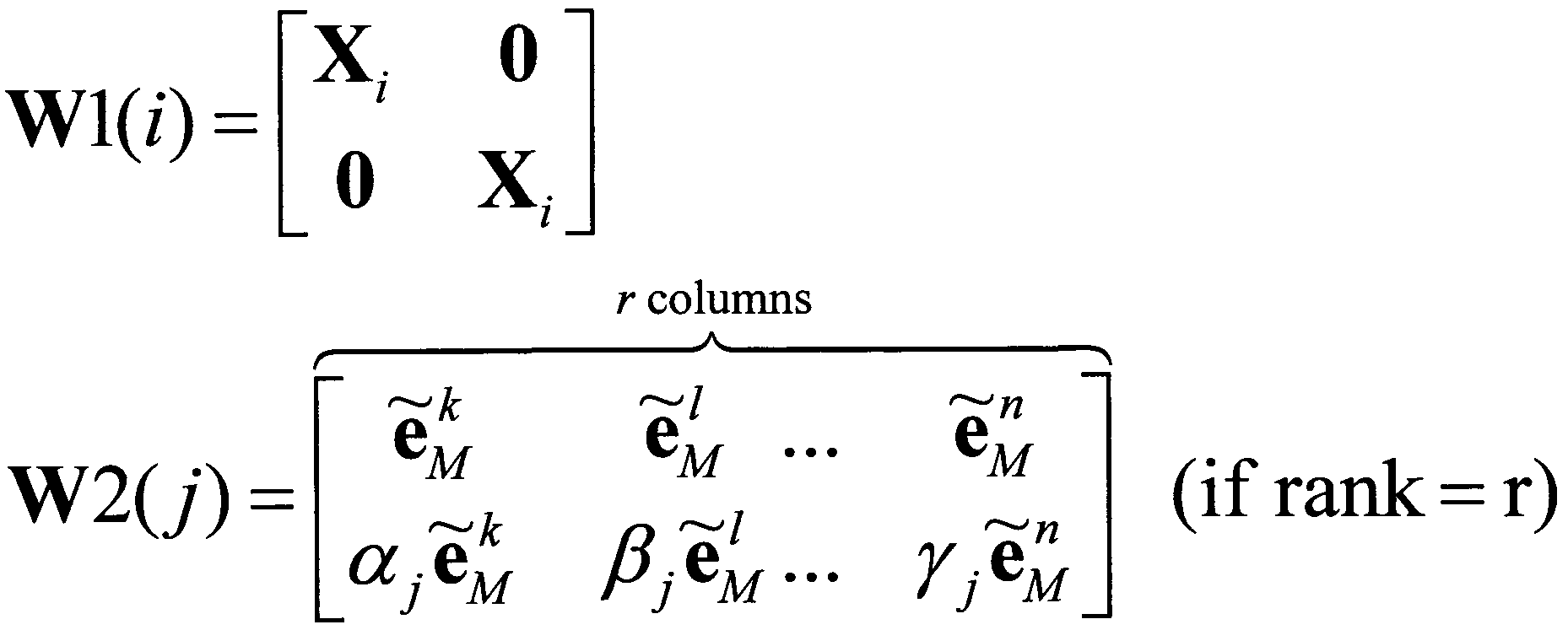



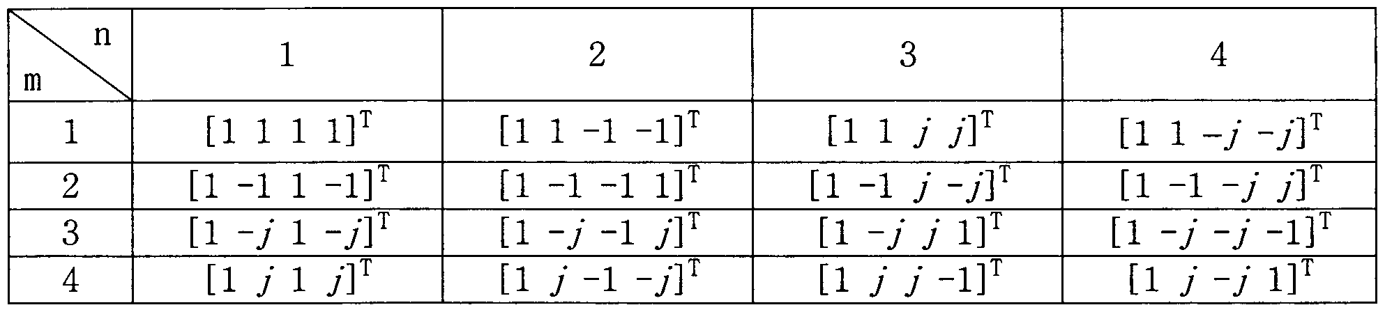
Claims




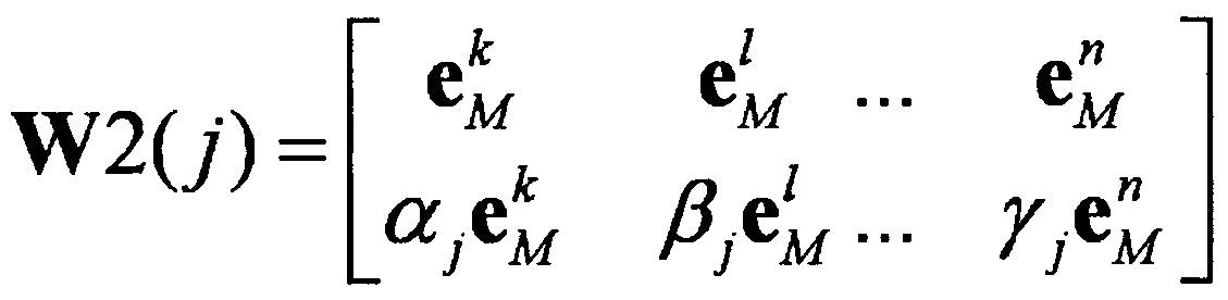


Priority Applications (2)
| Application Number | Priority Date | Filing Date | Title |
|---|---|---|---|
| US13/812,218 US8885754B2 (en) | 2010-07-29 | 2011-07-28 | Method and device for sending and receiving precoded signals on a wireless communication system |
| KR1020127033375A KR101754669B1 (ko) | 2010-07-29 | 2011-07-28 | 무선 통신 시스템에서 프리코딩된 신호 송수신 방법 및 장치 |
Applications Claiming Priority (2)
| Application Number | Priority Date | Filing Date | Title |
|---|---|---|---|
| US36903210P | 2010-07-29 | 2010-07-29 | |
| US61/369,032 | 2010-07-29 |
Publications (2)
| Publication Number | Publication Date |
|---|---|
| WO2012015252A2 true WO2012015252A2 (ko) | 2012-02-02 |
| WO2012015252A3 WO2012015252A3 (ko) | 2012-05-24 |
Family
ID=45530616
Family Applications (1)
| Application Number | Title | Priority Date | Filing Date |
|---|---|---|---|
| PCT/KR2011/005561 Ceased WO2012015252A2 (ko) | 2010-07-29 | 2011-07-28 | 무선 통신 시스템에서 프리코딩된 신호 송수신 방법 및 장치 |
Country Status (3)
| Country | Link |
|---|---|
| US (1) | US8885754B2 (ko) |
| KR (1) | KR101754669B1 (ko) |
| WO (1) | WO2012015252A2 (ko) |
Cited By (4)
| Publication number | Priority date | Publication date | Assignee | Title |
|---|---|---|---|---|
| WO2014135993A1 (en) * | 2013-03-07 | 2014-09-12 | Broadcom Corporation | Method, apparatus and computer program for controlling a wireless device |
| CN104135314A (zh) * | 2013-04-30 | 2014-11-05 | 上海贝尔股份有限公司 | Mimo系统中的多天线信道码本反馈方法及装置 |
| EP2710758A4 (en) * | 2012-05-11 | 2015-10-21 | Panasonic Ip Corp America | Method of csi reporting, user equipment and enode b |
| EP2945306A4 (en) * | 2013-03-08 | 2016-02-24 | Huawei Tech Co Ltd | PRE-CODING MATRIX DISPLAY FEEDBACK METHOD, RECEIVER AND TRANSMISSION END |
Families Citing this family (23)
| Publication number | Priority date | Publication date | Assignee | Title |
|---|---|---|---|---|
| CN102171946B (zh) * | 2011-04-22 | 2013-09-11 | 华为技术有限公司 | 数据传输方法和装置 |
| EP2761771A4 (en) * | 2011-09-29 | 2015-06-24 | Intel Corp | MU-MIMO OF SUPERIOR ORDER FOR LTE-A |
| US9949265B2 (en) * | 2012-05-04 | 2018-04-17 | Comcast Cable Communications, Llc | Control channel in a wireless communication system |
| US9130621B2 (en) * | 2013-01-10 | 2015-09-08 | Broadcom Corporation | Communication system using a multi-antenna transmit precoder codebook |
| WO2014129871A1 (ko) * | 2013-02-25 | 2014-08-28 | 엘지전자 주식회사 | 다중 안테나 무선 통신 시스템에서 효율적인 신호 송신 방법 및 이를 위한 장치 |
| US9755716B2 (en) * | 2013-03-07 | 2017-09-05 | Nec Corporation | Codebook construction |
| JP6479764B2 (ja) * | 2013-04-07 | 2019-03-06 | アルカテル−ルーセント | チャネル状態情報を量子化する方法および装置 |
| RU2630378C2 (ru) * | 2013-04-28 | 2017-09-07 | Хуавей Текнолоджиз Ко., Лтд. | Способ обратной связи по указателю матрицы предварительного кодирования, сторона приема и сторона передачи |
| WO2014178615A1 (ko) * | 2013-04-29 | 2014-11-06 | 엘지전자 주식회사 | 무선 통신 시스템에서 채널상태정보 전송 방법 및 장치 |
| KR102186144B1 (ko) * | 2014-02-21 | 2020-12-03 | 삼성전자주식회사 | 다중 입력 다중 출력 시스템에서 채널 관련 정보 송/수신 장치 및 방법 |
| JP6339666B2 (ja) * | 2014-03-18 | 2018-06-06 | アルカテル−ルーセント | Mimoシステム内の複数アンテナ・チャネルに関するコードブック・フィードバックの方法および装置 |
| US9590708B1 (en) * | 2015-08-25 | 2017-03-07 | Motorola Mobility Llc | Method and apparatus for equal energy codebooks for antenna arrays with mutual coupling |
| CN106656285B (zh) * | 2015-10-30 | 2021-03-16 | 中兴通讯股份有限公司 | 一种通信方法、终端及通信系统 |
| CN110034797B (zh) * | 2016-04-01 | 2020-06-26 | 华为技术有限公司 | 一种预编码矩阵指示的反馈方法及装置 |
| US10659118B2 (en) * | 2016-04-19 | 2020-05-19 | Samsung Electronics Co., Ltd. | Method and apparatus for explicit CSI reporting in advanced wireless communication systems |
| CN107370530B (zh) * | 2016-05-12 | 2021-02-12 | 华为技术有限公司 | 信道状态信息反馈方法、预编码方法、终端设备和基站 |
| CN107453851B (zh) * | 2016-05-30 | 2020-02-14 | 华为技术有限公司 | 一种cqi测量方法、装置及无线通信系统 |
| CN110545130B (zh) * | 2016-11-04 | 2020-08-07 | 华为技术有限公司 | 信道状态信息接收方法、用户设备和网络设备 |
| US12369149B2 (en) * | 2020-07-20 | 2025-07-22 | Qualcomm Incorporated | Uplink rank adaptation for MIMO communication |
| US12073868B2 (en) * | 2022-06-07 | 2024-08-27 | Micron Technology, Inc. | Timing adjustment for data input/output buffer circuits |
| US11909472B2 (en) | 2021-11-16 | 2024-02-20 | Samsung Electronics Co., Ltd | Method and apparatus for selection of linear combination coefficients for precoding in frequency-selective channels |
| US12155429B2 (en) | 2022-01-19 | 2024-11-26 | Samsung Electronics Co., Ltd. | Systems, methods, and apparatus for determining precoding information for beamforming |
| KR102689251B1 (ko) * | 2022-03-28 | 2024-07-30 | 한국과학기술원 | 지능형 반사 표면을 이용한 무선 에너지 하베스팅 극대화를 위한 컴퓨터 시스템 및 그의 방법 |
Family Cites Families (7)
| Publication number | Priority date | Publication date | Assignee | Title |
|---|---|---|---|---|
| TWI343200B (en) | 2006-05-26 | 2011-06-01 | Lg Electronics Inc | Method and apparatus for signal generation using phase-shift based pre-coding |
| EP2055014B1 (en) * | 2006-08-25 | 2013-03-06 | Ikanos Technology Ltd. | Systems and methods for mimo precoding in an xdsl system |
| ATE539499T1 (de) | 2007-02-14 | 2012-01-15 | Lg Electronics Inc | Datensende- und empfangsverfahren mit auf phasenverschiebung basierender vorcodierung und dieses unterstützender sender/empfänger |
| WO2008133582A2 (en) * | 2007-04-30 | 2008-11-06 | Telefonaktiebolaget L M Ericsson (Publ) | Method and arrangement for adapting a multi-antenna transmission |
| WO2009025493A2 (en) | 2007-08-22 | 2009-02-26 | Lg Electronics Inc. | Method for transmitting/receiving data in multiple-input multiple-output system using multi-carrier |
| EP2232726B1 (en) * | 2008-01-14 | 2017-02-08 | Telefonaktiebolaget LM Ericsson (publ) | Open loop precoder cycling in mimo communications |
| US8315221B2 (en) * | 2010-06-18 | 2012-11-20 | Sharp Laboratories Of America, Inc. | Reducing feedback overhead for multiple component carriers |
-
2011
- 2011-07-28 KR KR1020127033375A patent/KR101754669B1/ko not_active Expired - Fee Related
- 2011-07-28 US US13/812,218 patent/US8885754B2/en not_active Expired - Fee Related
- 2011-07-28 WO PCT/KR2011/005561 patent/WO2012015252A2/ko not_active Ceased
Cited By (9)
| Publication number | Priority date | Publication date | Assignee | Title |
|---|---|---|---|---|
| EP2710758A4 (en) * | 2012-05-11 | 2015-10-21 | Panasonic Ip Corp America | Method of csi reporting, user equipment and enode b |
| US10051489B2 (en) | 2012-05-11 | 2018-08-14 | Sun Patent Trust | Method of CSI reporting, user equipment and enode B |
| WO2014135993A1 (en) * | 2013-03-07 | 2014-09-12 | Broadcom Corporation | Method, apparatus and computer program for controlling a wireless device |
| US9490883B2 (en) | 2013-03-07 | 2016-11-08 | Broadcom Corporation | Method, apparatus and computer program for controlling a wireless device |
| EP2945306A4 (en) * | 2013-03-08 | 2016-02-24 | Huawei Tech Co Ltd | PRE-CODING MATRIX DISPLAY FEEDBACK METHOD, RECEIVER AND TRANSMISSION END |
| EP3484075A1 (en) * | 2013-03-08 | 2019-05-15 | Huawei Technologies Co. Ltd. | Method for feeding back precoding matrix indicator, receive end and transmit end |
| CN104135314A (zh) * | 2013-04-30 | 2014-11-05 | 上海贝尔股份有限公司 | Mimo系统中的多天线信道码本反馈方法及装置 |
| WO2014177921A1 (en) * | 2013-04-30 | 2014-11-06 | Alcatel Lucent | Cqdebqqk feedback methqd and apparatus for multiple-antenna channel in mimq system |
| US9496941B2 (en) | 2013-04-30 | 2016-11-15 | Alcatel Lucent | Codebook feedback method and apparatus for multiple-antenna channel in MIMO system |
Also Published As
| Publication number | Publication date |
|---|---|
| WO2012015252A3 (ko) | 2012-05-24 |
| KR20130094220A (ko) | 2013-08-23 |
| US8885754B2 (en) | 2014-11-11 |
| KR101754669B1 (ko) | 2017-07-06 |
| US20130129014A1 (en) | 2013-05-23 |
Similar Documents
| Publication | Publication Date | Title |
|---|---|---|
| US11388685B2 (en) | Configurable codebook for advanced CSI feedback overhead reduction | |
| US11831379B2 (en) | Method for feeding backchannel state information, user equipment, and base station | |
| KR101754669B1 (ko) | 무선 통신 시스템에서 프리코딩된 신호 송수신 방법 및 장치 | |
| KR102284070B1 (ko) | 작은 제어 채널들 상에서의 csi 보고 | |
| KR101832766B1 (ko) | 무선 통신 시스템에서 코드북을 이용한 신호 송수신 방법 및 장치 | |
| KR101753589B1 (ko) | 다중-셀 협력 통신 모드 및 단일-셀 mimo 통신 모드 간의 모드 스위칭 방법 및 장치 | |
| EP2993805B1 (en) | Method and apparatus for transmitting channel state information in wireless communication system | |
| US9203490B2 (en) | Method and apparatus for transmitting channel status information in wireless communication system | |
| US9509383B2 (en) | Method and apparatus for transmitting channel state information in wireless communication system | |
| CN105340192B (zh) | 映射码字的方法、无线电基站和计算机可读存储介质 | |
| KR20180071387A (ko) | 무선 통신 시스템에서 dm-rs 기반 개루프 하향링크 전송을 위한 피드백 정보 송신 방법 및 이를 위한 장치 | |
| WO2014046429A1 (ko) | 다중 안테나 무선 통신 시스템에서 효율적인 피드백 전송 방법 및 이를 위한 장치 | |
| KR20150100648A (ko) | 다중 안테나 무선 통신 시스템에서 효율적인 피드백 전송 방법 및 이를 위한 장치 | |
| WO2014010912A1 (ko) | 무선 통신 시스템에서 코드북을 이용한 피드백 전송 방법 및 이를 위한 장치 | |
| WO2015190866A1 (ko) | 다중 안테나 무선 통신 시스템에서 코드북 구성 방법 및 이를 위한 장치 | |
| KR101572895B1 (ko) | 무선 통신 시스템에서 채널상태정보를 전송하는 방법 및 장치 | |
| CN105075141A (zh) | 在无线通信系统中发送信道状态信息的方法和装置 | |
| WO2017014486A1 (ko) | 무선 통신 시스템에서 csi를 보고하는 방법 및 이를 위한 장치 |
Legal Events
| Date | Code | Title | Description |
|---|---|---|---|
| 121 | Ep: the epo has been informed by wipo that ep was designated in this application |
Ref document number: 11812781 Country of ref document: EP Kind code of ref document: A2 |
|
| ENP | Entry into the national phase |
Ref document number: 20127033375 Country of ref document: KR Kind code of ref document: A |
|
| WWE | Wipo information: entry into national phase |
Ref document number: 13812218 Country of ref document: US |
|
| NENP | Non-entry into the national phase |
Ref country code: DE |
|
| 122 | Ep: pct application non-entry in european phase |
Ref document number: 11812781 Country of ref document: EP Kind code of ref document: A2 |