WO2012017566A1 - Actionneur pour générateur d'aérosol - Google Patents
Actionneur pour générateur d'aérosol Download PDFInfo
- Publication number
- WO2012017566A1 WO2012017566A1 PCT/JP2010/067407 JP2010067407W WO2012017566A1 WO 2012017566 A1 WO2012017566 A1 WO 2012017566A1 JP 2010067407 W JP2010067407 W JP 2010067407W WO 2012017566 A1 WO2012017566 A1 WO 2012017566A1
- Authority
- WO
- WIPO (PCT)
- Prior art keywords
- scraping
- actuator
- aerosol container
- flow path
- cleaning
- Prior art date
- Legal status (The legal status is an assumption and is not a legal conclusion. Google has not performed a legal analysis and makes no representation as to the accuracy of the status listed.)
- Ceased
Links
Images


Classifications
-
- B—PERFORMING OPERATIONS; TRANSPORTING
- B05—SPRAYING OR ATOMISING IN GENERAL; APPLYING FLUENT MATERIALS TO SURFACES, IN GENERAL
- B05B—SPRAYING APPARATUS; ATOMISING APPARATUS; NOZZLES
- B05B15/00—Details of spraying plant or spraying apparatus not otherwise provided for; Accessories
- B05B15/50—Arrangements for cleaning; Arrangements for preventing deposits, drying-out or blockage; Arrangements for detecting improper discharge caused by the presence of foreign matter
- B05B15/52—Arrangements for cleaning; Arrangements for preventing deposits, drying-out or blockage; Arrangements for detecting improper discharge caused by the presence of foreign matter for removal of clogging particles
- B05B15/522—Arrangements for cleaning; Arrangements for preventing deposits, drying-out or blockage; Arrangements for detecting improper discharge caused by the presence of foreign matter for removal of clogging particles using cleaning elements penetrating the discharge openings
- B05B15/5223—Arrangements for cleaning; Arrangements for preventing deposits, drying-out or blockage; Arrangements for detecting improper discharge caused by the presence of foreign matter for removal of clogging particles using cleaning elements penetrating the discharge openings the cleaning element, e.g. a needle, and the discharge opening being movable relative to each other in a direction substantially parallel to the flow of liquid or other fluent material through said opening
-
- B—PERFORMING OPERATIONS; TRANSPORTING
- B65—CONVEYING; PACKING; STORING; HANDLING THIN OR FILAMENTARY MATERIAL
- B65D—CONTAINERS FOR STORAGE OR TRANSPORT OF ARTICLES OR MATERIALS, e.g. BAGS, BARRELS, BOTTLES, BOXES, CANS, CARTONS, CRATES, DRUMS, JARS, TANKS, HOPPERS, FORWARDING CONTAINERS; ACCESSORIES, CLOSURES, OR FITTINGS THEREFOR; PACKAGING ELEMENTS; PACKAGES
- B65D83/00—Containers or packages with special means for dispensing contents
- B65D83/14—Containers for dispensing liquid or semi-liquid contents by internal gaseous pressure, i.e. aerosol containers comprising propellant
- B65D83/16—Actuating means
-
- B—PERFORMING OPERATIONS; TRANSPORTING
- B65—CONVEYING; PACKING; STORING; HANDLING THIN OR FILAMENTARY MATERIAL
- B65D—CONTAINERS FOR STORAGE OR TRANSPORT OF ARTICLES OR MATERIALS, e.g. BAGS, BARRELS, BOTTLES, BOXES, CANS, CARTONS, CRATES, DRUMS, JARS, TANKS, HOPPERS, FORWARDING CONTAINERS; ACCESSORIES, CLOSURES, OR FITTINGS THEREFOR; PACKAGING ELEMENTS; PACKAGES
- B65D83/00—Containers or packages with special means for dispensing contents
- B65D83/14—Containers for dispensing liquid or semi-liquid contents by internal gaseous pressure, i.e. aerosol containers comprising propellant
- B65D83/34—Cleaning or preventing clogging of the discharge passage
-
- B—PERFORMING OPERATIONS; TRANSPORTING
- B65—CONVEYING; PACKING; STORING; HANDLING THIN OR FILAMENTARY MATERIAL
- B65D—CONTAINERS FOR STORAGE OR TRANSPORT OF ARTICLES OR MATERIALS, e.g. BAGS, BARRELS, BOTTLES, BOXES, CANS, CARTONS, CRATES, DRUMS, JARS, TANKS, HOPPERS, FORWARDING CONTAINERS; ACCESSORIES, CLOSURES, OR FITTINGS THEREFOR; PACKAGING ELEMENTS; PACKAGES
- B65D83/00—Containers or packages with special means for dispensing contents
- B65D83/14—Containers for dispensing liquid or semi-liquid contents by internal gaseous pressure, i.e. aerosol containers comprising propellant
- B65D83/68—Dispensing two or more contents
Definitions
- the present invention relates to an actuator for an aerosol container, in which a residue after injection is present in a communicating path from a stem, which is scraped off and easily cleaned.
- a residue after injection is present in a communicating path from a stem, which is scraped off and easily cleaned.
- two undiluted solutions such as a creamy hair dye This prevents the clogging of the actuator that injects the fuel.
- the aerosol valve cannot be reused, and in many cases, it is preferable that the aerosol valve is not mixed in the aerosol valve but distributed and injected outside through the actuator.
- the connecting member is fitted to a pair of left and right aerosol cans to be in a connected state, and the first fitting cylinder suspended from the passage member is used as the stem of the aerosol can.
- a second fitting cylinder is formed by being raised, and a main cylinder member is detachably fitted to the outer surface of the passage member and the connecting member, and a head with a nozzle and an operating lever are fitted to the main cylinder member.
- a cap provided with is attached.
- a nozzle in which a guide path is formed is fitted to the stems of two aerosol containers placed side by side, and an operation lever is provided on a cover that covers the nozzle, The nozzle is configured to be detachable with the cover attached. In the case of cleaning, the nozzle is taken out and cleaned while leaving the cover, and a separately prepared nozzle cleaner is connected to the guide path of the nozzle, and then the fluid is sucked and discharged by the pump unit. It has come to be.
- Such a structure of removing and cleaning the passage member of Patent Document 1 has a problem that even if water is applied to the residue clogged in the narrow passage, it cannot be easily cleaned, and a knob plate is provided. However, there are problems such as residue sticking to the hand when taking out.
- the present invention has been made to solve the above-described problems in the prior art, and provides an actuator for an aerosol container in which a residue after injection is present in the communication path from the stem and can be easily cleaned by scraping it out. It is what.
- an actuator for an aerosol container surrounds and fixes a plurality of stems of the aerosol container, and is provided in the actuator body and communicates with each stem.
- a scraping cleaning member equipped with a flow path portion that forms a flow path of the internal solution and a scraping portion that scrapes off the residue after injection, and a holding that holds the scraping cleaning member at the scraping cleaning position pulled out from the communication path Means.
- an aerosol container actuator wherein, in addition to the configuration of the first aspect, the nozzle body is pivotally connected to the actuator body via a hinge portion so as to be in a rotational state.
- the scraping cleaning position is configured to be washable.
- an actuator for an aerosol container in addition to the configuration according to the first or second aspect, includes a holding arm for holding the scraping cleaning position, a locking arm provided on the nozzle body, This locking arm is constituted by a cleaning locking portion that locks at the cleaning position.
- the actuator for an aerosol container includes a holding arm for holding the scraping cleaning position, a locking arm provided on the nozzle body, and the engagement member. It is characterized in that it is provided with an injection locking portion for locking the stop arm at the injection position.
- the actuator for an aerosol container according to claim 5 of the present invention has a configuration in which at least two locations of the lower end portion and the intermediate portion of the scraping cleaning member are flown in addition to the configuration according to any one of claims 1 to 4.
- the path portion and the scraping portion are formed in an inverted manner, and both the securing of the flow path and the scraping of the residue are configured.
- the actuator for an aerosol container has a flow path portion by forming a helical projection on the scraped cleaning member. And a scraping portion.
- an actuator for an aerosol container according to a seventh aspect of the present invention includes the aerosol container according to any one of the first to sixth aspects, wherein the aerosol container is provided in a plurality of inch cans having an opening diameter of 1 inch. It is characterized by being provided with a stem.
- the residue means not only the residue of the liquid stock solution filled in the aerosol container, but also the residue of the gel, foam or cream stock solution.
- an actuator main body that is mounted and fixed around a plurality of stems of the aerosol container, and a plurality of independent communication units that are provided in the actuator main body and communicate with the stems.
- a scraping cleaning member provided with a channel portion that forms the channel and a scraping portion that scrapes the residue after injection, and holding means for holding the scraping cleaning member at the scraping cleaning position pulled out from the communication path.
- the scraping cleaning member is pulled out from the nozzle outlet of the nozzle body and held at the cleaning position by the holding means to scrape the residue in the communication path. Kiyoshi scraped it can at the raking of the member, by flowing the water scraping portion as a cleaning path, unlike the fully closed state, it can be easily cleaned. On the other hand, even in a state where the scraping cleaning member is inserted, the flow path can be secured by the flow path portion and smooth injection can be maintained.
- the nozzle body is rotatably connected to the actuator body via a hinge portion, and the rotation state can be cleaned as a cleaning position. Since it is configured, by rotating the nozzle body and the scraping cleaning member with respect to the actuator body at the time of cleaning to the scraping cleaning position, it is more easily cleaned with running water etc. in a state where the direction is changed from the aerosol container. be able to.
- the holding means for holding the scraping cleaning position includes a locking arm provided in the nozzle body, and the locking arm at the scraping cleaning position. Since it is composed of a locking part for cleaning, the locking arm is locked to the locking part for cleaning without cleaning, so that the cleaning member is not completely removed from the nozzle body at the cleaning position. It is possible to hold the scraping cleaning member without losing it as it is cleaned, and it can be easily done by pushing in the reassembly.
- the holding means for holding the scraping cleaning position is engaged with the locking arm provided in the nozzle body and the locking arm at the injection position. Since it is configured to be provided with an injection locking part that stops, by locking the locking arm to the injection locking part at the time of injection, the scraping cleaning member can be held without being pulled out along with the injection, It can be ejected in a stable state.
- the flow path portion and the scraping portion are formed by reversing at least two locations, the lower end portion and the intermediate portion of the scraping member. Since the flow path is secured and the residue is scraped out, the flow path section and the scraping section are reversed so that the flow path is formed by the flow path sections at at least two inverted positions. It can be ensured and ejected, and the remaining amount in one flow path portion can be scraped out by the other scraping portion.
- the spiral cleaning portion is formed on the scraped cleaning member to form the flow path portion and the scraping portion. It is possible to achieve both securing of the flow path and scraping of the residue.
- the aerosol container is formed by providing a plurality of stems in an inch can having an opening diameter of 1 inch. Even with an actuator provided in an aerosol container provided with a plurality of stems, such as two cans, by using a cleaning member, securing of the flow path and scraping of the residue can be achieved at the same time.
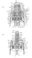
- FIG. 5 is a central longitudinal sectional view (corresponding to the AA ′ section in FIG. 4) and an BB ′ sectional view in FIG. 4 according to an embodiment of the actuator for an aerosol container of the present invention. It is the front view concerning an embodiment of the actuator for aerosol containers of the present invention, a top view, and a side view.
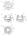
- FIG. 2 is a central longitudinal view, a plan view, and a BB ′ sectional view of a scraped cleaning member according to an embodiment of an actuator for an aerosol container of the present invention.
- FIG. 4 is a front view, a plan view, a bottom view, and a side view illustrating the flow path portion and the scraping portion according to the embodiment of the scraping cleaning member of the actuator for the aerosol container of the present invention. It is the front view of the scraping washing state concerning one embodiment of the actuator for aerosol containers of the present invention, and the partial sectional view explaining the process.
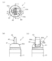
- 1 is a front view, a side view, and a central longitudinal sectional view according to an embodiment of an actuator for an aerosol container of the present invention.
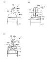
- FIG. 4 is a front view and a partial cross-sectional view of a scraped cleaning state according to an embodiment of the actuator for an aerosol container of the present invention.
- a plurality of stems of the aerosol container 11, for example, two stems 15, 15 are attached and distributed without mixing from the respective stems 15, 15. It is possible to inject, and the residue in the actuator 1 after the injection can be easily cleaned.
- the aerosol container to which the actuator 1 for an aerosol container is applied is an aerosol container as shown in FIG. 2 instead of being applied to two stems in which two conventional aerosol containers are aligned and connected by a connecting member.
- 11 is an example of a mode of application to two stems 15 and 15 of one inch can provided with two sets of aerosol valves in an inch can having a bead portion having a diameter of 1 inch that is generally used as a standard product.
- the synthetic resin mounting member 13 is fitted and mounted on the bead portion 12 of the aerosol container 11 as shown in FIG. Then, two sets of valve housing mounting portions 14 and 14 are formed on the mounting member 13. And the aerosol valve provided with the stems 15 and 15 to each valve housing mounting part 14 and 14 is mounted
- This mounting member 13 includes a mounting portion main body 13a having a substantially cylindrical outer shape, and a collar portion 13b is formed on the outer periphery of the intermediate portion so that it can be brought into contact with the upper surface of the bead portion 12 of the aerosol container 11. It is. And eight engagement pieces formed with engagement protrusions formed on the inner periphery of the bead portion 12 below the intermediate portion of the collar portion 13b are provided at equal circumferential intervals, and the upper end portions of the respective engagement pieces.
- the mounting portion main body 13a is supported by radial radial ribs, and can be elastically deformed by a buffer space formed between the mounting portion main body 13a. Thereby, the mounting member 13 can be fitted and mounted on the bead portion 12 by being pushed into the bead portion 12 of the aerosol container 11 from above.
- the small cylindrical valve housing mounting portions 14 and 14 parallel to the vertical direction sandwich the central axis of the mounting member 13.
- Two flat side wall surfaces protruding from the upper part of the mounting portion main body 13a are made parallel to each other, and the valve housing mounting portion is formed in the tip protruding portion 13c formed in a substantially oval shape with the semicircular wall surfaces at both ends thereof.
- the upper end portions of 14 and 14 are arranged.
- Engagement claws are formed on the inner periphery of the intermediate part of the valve housing mounting parts 14, 14, and the engagement step formed on the outer periphery of the intermediate part of the valve housing 16, 16 of the aerosol valve can be engaged and fixed. It is like that.
- a dip tube 17 is connected to a tube mounting portion 16b formed in the lower end portion with a valve chamber 16a formed in the middle upper portion. Further, an inner bag 18 whose volume can be changed by the pressure of the propellant is attached to the outside of the dip tube 17.
- the stem 15 is integrally formed of a stem body 15a and a stem protrusion 15b, and an injection path 15c is formed at the center of the stem protrusion 15b.
- An orifice 15d communicating with the valve chamber 16a is opened laterally at a position corresponding to the upper surface of the stem body 15a in the passage 15d.
- the stem 15 and the integral stem body 15a are biased upward by a spring 15e attached to the bottom of the valve chamber 16a.
- Each stem 15 passes through the center hole of an annular stem gasket 15f that is opened and closed as a valve.
- an orifice 15d that opens to the side of the stem 15 is provided. And the communication between the valve chamber 16a and the injection path 15c is cut off.
- the stem gasket 15f itself bends, thereby opening the orifice 15d and connecting the valve chamber 16a and the injection path 15c of the stem 15 to each other. It can be communicated.
- the stem gasket 15f that is opened and closed as the valve is arranged so that the periphery spans the upper surface of the valve housing 16 and the upper surface of the tip protrusion 13c of the mounting member 13, and the upper surface of the valve housing 16 and the tip protrusion of the mounting member 13
- the stem gasket 15f is pressed from above by a seal point formed by a double concentric annular protrusion formed on the upper surface of the 13c so that the surface pressure can be increased to seal the stem gasket 15f.
- an integral stem gasket 15f is used corresponding to the two stems 15 and 15, and the one formed corresponding to the upper surface shape of the substantially oval tip protruding portion 13c is used.
- a covering member 19 made of a metal plate is provided so as to cover the outside of the mounting member 13 and the valve housings 16, 16, and is made of, for example, aluminum.
- the gasket 15f is pressed and the outer periphery of the lower end is crimped and fixed to the outside of the bead portion 12 of the aerosol container 11.
- the covering body 19 has a shape in which the uppermost portion covers the outside of the substantially long columnar shape of the tip protruding portion 13 c of the mounting member 16, and a small-diameter cylindrical portion, a large-diameter cylindrical portion, and a crimp portion continuous therebelow.
- a seal gasket 20 is disposed between the upper surface of the bead portion 12 and the collar portion 13b of the mounting member 13. By crimping, the aerosol container 11 is sealed with improved sealing performance.
- a lower valve chamber 16d is formed below the valve chamber 16a of the valve housing 16 in order to smoothly perform the filling operation and adjust the injection flow rate. 21 is attached.
- the poppet valve 21 is pushed down so that the periphery is a flow path so that the internal solution can be filled in a short time.
- the injection flow rate can be regulated in the central flow path.
- the covering 19 holds one stem gasket 15 f corresponding to the two stems 15, 15, but the area thereof is larger than that of the stem gasket corresponding to the conventional one stem.
- the pressure receiving area to which the internal pressure of the aerosol container 11 is applied becomes larger correspondingly to the area of the tip protruding portion 13c.
- a reinforcing cover member 30 made of synthetic resin is provided to hold the stem gasket 15f and prevent the covering 19 from being deformed, and covers the outside of the tip protruding portion 13c of the mounting member 13.
- the stem gasket 15f is pressed by the rigidity of the synthetic resin reinforcing cover member 30, and the covering 19 is prevented from being deformed.
- An actuator 1 for an aerosol container provided in an aerosol container 11 having two stems 15 and 15 in such an inch can includes an actuator main body 41 that is mounted and fixed around the two stems 15 and 15 of the aerosol container 11, and A nozzle body 42 provided in the actuator body 41 and having two independent communication passages communicating with the stems 15, 15, an injection port at one end portion, and a fitting connection portion to each stem at the other end portion; A scraping cleaning member 43 having a flow path portion that is removably attached to the communication path from the spray port of the nozzle body 42 and forms a flow path of the internal solution, and a scraping portion that scrapes off the residue after spraying, and this scraping And holding means 44 for holding the cleaning member 43 in the scraped cleaning position pulled out from the communication path.
- the scraping cleaning member 43 is pulled out from the ejection port of the nozzle main body 42 and held in the scraping cleaning position by the holding means 44, so that the residue in the communication path can be scraped out.
- the residue in the communication path can be scraped out.
- the actuator body 41 of the actuator 1 constitutes a cover of the aerosol container 11 and has an upper part formed in a dome shape, and a cylindrical outer body part 41 a that contacts the upper end of the can body of the aerosol container 11 hangs down from the lower part.
- the middle body portion 41b is formed to hang down inside thereof to form a double cylindrical shape. Then, the actuator main body 41 is mounted and fixed so as to be fitted to the bead portion 12 by the fitting claws 41 c formed by protruding to the inner periphery of the middle barrel portion 41 b and surround the stems 15 and 15 of the aerosol container 11.
- the dome shape of the actuator main body 41 has an inner body having a shape corresponding to the substantially oval outer periphery of the tip protruding portion 13c of the mounting member 13 inside the double cylindrical outer body portion 41a and the middle body portion 41b.
- a portion 41 d is formed to hang down, and a lower end portion of the inner body portion 41 d is in contact with the outer periphery of the covering body 19.
- the operation side (the right side of FIG. 5A) of the inner body part 41d is a low top plate part 41e, the upper ends of the middle body part 41b and the outer body part 41a are closed, and the opposite side to the operation side is drooping.
- Rotating support portions 41f are formed which are formed with parallel side walls and open downward.
- the nozzle main body 42 mounted inside the actuator main body 41 has a substantially elliptical cross-sectional shape, and two cylindrical communication passages 42a and 42a communicating with the stems 15 and 15 are provided on the inner side.
- the upper end portion is the injection ports 42b and 42b, while the lower end portion is the fitting connection portion 42c and 42c with the stems 15 and 15.
- An operation lever 42d is formed on the operation side of the nozzle body 42 so as to protrude outward and is disposed above the top plate portion 41e. On the opposite side, the operation lever 42d is supported by a rotation support portion 41f of the actuator body 41.
- a horizontal rotation shaft portion 42e is formed to protrude.
- the nozzle body 42 is formed with guide grooves 42f for guiding the insertion and removal of the cleaning member 43 on both outer sides of the long diameter, and a stopper 42g serving as a locking portion at the time of cleaning is formed above the guide groove 42f.
- a locking hole 42h serving as a locking portion at the time of injection is formed in the lower part.
- a scraping cleaning member 43 for scraping and cleaning the residue is attached to the nozzle body 42 so as to be detachable from the injection ports 42b and 42b.
- the scraping cleaning member 43 has an injection hole 43a formed in the top surface portion, and two scraping bar portions 43b that are inserted and removed from the upper partition portion of the injection hole 43a into the communication passages 42a and 42a of the nozzle body 42. Formed. These two scraping bar portions 43b are arranged so as to be positioned at the ends of the communication passages 42a and 42a.
- Each scraping bar portion 43b and 43b has a disk-like shape protruding horizontally at the lower end portion and the intermediate portion.
- a scraping plate 43c is provided.
- the scraping plate 43c at the lower end is formed with a notch groove at the center opposite to the scraping bar portion 43b to be a flow path portion 43d, and the remaining portion is a scraping portion 43e.
- the scraping plate 43c in the middle part two notch grooves are formed on both sides of the central part opposite to the scraping bar part 43b by reversing the lower end part to form the flow path part 43d, and the remaining part is the scraping part. 43e.
- the upper and lower portions of the intermediate scraping plate 43c and the channel portion 43d of the notch groove of each scraping plate 43c serve as the flow path of the internal solution at the time of injection, and the residue remaining in the flow channel is removed from the scraping plate.
- the residue remaining in the intermediate flow path portion can be scraped out by the scraping portion at the lower end by scraping the scraping portion 43e at 43c.
- the scraping cleaning member 43 a flow path at the time of cleaning can be ensured, and a portion where the scraping bar portion 43b is pulled out also becomes a flow path at the time of cleaning, and at the time of continuous cleaning from the upper end injection hole 43a to the lower end portion. Can be secured.
- the scraping cleaning member 43 is provided with holding means 44 for holding at the scraping cleaning position pulled out from the nozzle main body 42, and holding arms 44 a and 44 a protrude downward on both sides of the top surface portion of the scraping cleaning member 43. It is integrally formed and can be compressed by being sandwiched from both sides by the elasticity of synthetic resin, or can be returned to widen when released.
- the holding arms 44a and 44a are formed with L-shaped step portions 44b and 44b on the inner side of the lower end portion, and locking projections 44c and 44c protruding outward at the lower end portion.
- the locking projections 44c, 44c of the holding arms 44a, 44a are inserted into the locking holes 42h, 42h below the guide grooves 42f, 42f of the nozzle body 42.
- the injection state can be held, and the holding arms 44a and 44a can be pressed and compressed from both sides to release the locking state and withdrawn.
- the scraping cleaning member 43 when the scraping cleaning member 43 is pulled out from the nozzle body 42, the stepped portions 44b, 44b of the scraping cleaning member 43 are applied to the stoppers 42g, 42g on the upper portions of the guide grooves 42f, 42f of the nozzle body 42. It can be held in a scraped cleaning position where it cannot be pulled out.
- the shape of the flow path portion and the scraping portion formed on the scraping cleaning member 43 has various forms.
- the scraping rod portion 43b of the scraping cleaning member 43 is moved to the left and right.
- scraped plates 43c are provided at the intermediate portion and the lower end portion, respectively.
- a channel portion 43d of a notch groove is formed at the center, the remaining portion other than the channel portion 43d becomes a scraping portion 43e, and two notches are formed on both sides sandwiching the center portion at the intermediate portion.
- a channel part 43d is formed by forming a groove, and the remaining part other than the channel part 43d is a scraped part 43e.
- the flow path portion 43d at the reversed position can be secured and ejected, and The remaining amount in the flow path portion 43d can be scraped out by the other scraping portion 43e.
- the shape of the flow path portion and the scraping portion formed in the scraping cleaning member 43 is such that the scraping bar portion 43b of the scraping cleaning member 43 is arranged at the center of the scraping plate 43c, A scraping plate 43c is provided at each of the part and the lower end part.
- notched groove channel portions 43d are formed on both sides of the diagonal position, and the remaining portion other than the channel portion 43d serves as the scraping portion 43e, and the intermediate portion is perpendicular to the lower end portion.
- Two cutout grooves are formed on both sides of the corner position to form a flow path portion 43d, and the remaining portion other than the flow path portion 43d is a scraped portion 43e.
- the flow path portion 43d at the reversed position can be secured and ejected, and The remaining amount in the flow path portion 43d can be scraped out by the other scraping portion 43e.
- the shape of the flow path portion and the scraping portion formed in the scraping cleaning member 43 is arranged such that the scraping rod portion 43b of the scraping cleaning member 43 is arranged at the center portion and spirally formed around it.
- the scraping plate 43c is provided so that the space between the spiral portions serves as a flow path portion 43d and the spiral portion itself serves as a scraping portion 43e.
- a flow path can be secured and ejected between the spiral scraping plates 43c, and the remaining amount can be scraped with the scraping plate 43c.
- the actuator 1 is assembled by scraping the nozzle body 42 and inserting the cleaning member 43 into the communication passages 42a and 42a from the injection ports 42b and 42b, and locking the locking projections 44c and 44c of the holding arms 44a and 44a of the holding means 44.
- the holes 42h and 42h are inserted and locked, and a rotation shaft portion 42e of the nozzle body 42 is attached to the rotation support portion 41f of the actuator body 41 so as to be rotatable and the injection state is maintained.
- the actuator main body 41 is disposed so as to surround the two stems 15 and 15 of the aerosol container 11, and the fitting claw 41c is fitted to the outer periphery of the bead portion 12, whereby the actuator 1 is mounted.
- the injection of the internal solution by the actuator 1 is performed by pushing down the operation lever 42d while the actuator 1 is attached to the aerosol container 11 to push the two stems 15 and 15, and the internal solution is injected from the stems 15 and 15, respectively. Injected in a distributed state through the passages 15c and 15c, the communication passages 42a and 42a of the nozzle main body 42, the injection ports 42b and 42b, the flow path portions 43d and 43d of the scraping cleaning member 43, and the injection holes 43a and 43a. be able to.
- the scraping cleaning member 43 is pulled out from the nozzle body 42 to scrape the residue, so that the holding arms 44a and 44a of the holding means 44 are pushed in from both sides, and then the locking projection 44c. 44c are positioned in the locking holes 42h and 42h and pulled up to release the locked state.
- the scraping cleaning member 43 is pulled up so that the residue is scraped off by the scraping plates 43c and 43c, and the stepping portions 44b and 44b of the holding arms 44a and 44a are touched against the stoppers 42g and 42g of the nozzle body 42, and the scraping cleaning of the upper end of the lifting is performed. Hold in position.
- the nozzle body 42 is rotated about the rotation shaft portion 42e so that the nozzle body 42 is inclined by approximately 90 degrees with respect to the aerosol container 11.
- the scraping cleaning member 43 is held at the scraping cleaning position by the holding means 44, so that it is not lost due to running water during cleaning, and is stored separately for the next cleaning. It is not necessary and can be assembled by being pushed into the nozzle body 42 as it is, and is easy to handle.
- holding arms 44a and 44a are provided on both sides of the scraping cleaning member 43 as the holding means 44 and are held by the nozzle main body 42 by the step portions 44b and 44b and the locking projections 44c and 44c, the present invention is not limited to this. It can also be set as this structure.
- the holding means 44 is provided with one holding arm 44a at the center on the operation lever 42d side of the nozzle body 42, which is one side of the scraping cleaning member 43, and the operation portion 44d protrudes from the upper end.
- the locking projections 44c are provided at the lower end so as to protrude inward.
- the nozzle body 42 is formed with a vertical locking groove 44e through which the locking projection 44c moves.
- the locking projection 44c of the holding arm 44a is locked to the upper end of the locking groove 44e so that the locking groove 44e cannot be pulled up any more and can be held at the scraping cleaning position.
- Such holding means 44 also allows the scraping cleaning member 43 to be held at the scraping cleaning position by the holding means 44, and is not stored away for the next cleaning without being washed away by running water during cleaning. It is not necessary and can be assembled by being pushed into the nozzle body 42 as it is, and is easy to handle.
- the inner solution filled in the two inner bags of the aerosol container in which the actuator for the aerosol container is used it is preferable to mix a main agent and an additive in advance to cause a chemical reaction such as curing and oxidation.
- a main agent and an additive in advance to cause a chemical reaction such as curing and oxidation.
- the main ingredients and additives of aerosol products in the form of non-foamed forms can be mentioned, for example, suitable for aerosol products such as hot shaving cream, hair dyes, adhesives, paints, pharmaceuticals, especially clogged by drying etc. Suitable for easy creamy inner solution.
Landscapes
- Chemical & Material Sciences (AREA)
- Dispersion Chemistry (AREA)
- Engineering & Computer Science (AREA)
- Mechanical Engineering (AREA)
- Containers And Packaging Bodies Having A Special Means To Remove Contents (AREA)
- Nozzles (AREA)
Abstract
Priority Applications (5)
| Application Number | Priority Date | Filing Date | Title |
|---|---|---|---|
| EP10855655.6A EP2602209B1 (fr) | 2010-08-03 | 2010-10-05 | Actionneur pour générateur d'aérosol |
| KR1020137003276A KR101448701B1 (ko) | 2010-08-03 | 2010-10-05 | 에어로졸 용기용 액추에이터 |
| CN201080068409.7A CN103108813B (zh) | 2010-08-03 | 2010-10-05 | 用于气溶胶容器的促动器 |
| US13/811,484 US8925765B2 (en) | 2010-08-03 | 2010-10-05 | Actuator for an aerosol container |
| BR112013001172-6A BR112013001172B1 (pt) | 2010-08-03 | 2010-10-05 | Atuador para um recipiente aerossol |
Applications Claiming Priority (2)
| Application Number | Priority Date | Filing Date | Title |
|---|---|---|---|
| JP2010174321A JP5734594B2 (ja) | 2010-08-03 | 2010-08-03 | エアゾール容器用のアクチュエータ |
| JP2010-174321 | 2010-08-03 |
Publications (1)
| Publication Number | Publication Date |
|---|---|
| WO2012017566A1 true WO2012017566A1 (fr) | 2012-02-09 |
Family
ID=45559095
Family Applications (1)
| Application Number | Title | Priority Date | Filing Date |
|---|---|---|---|
| PCT/JP2010/067407 Ceased WO2012017566A1 (fr) | 2010-08-03 | 2010-10-05 | Actionneur pour générateur d'aérosol |
Country Status (7)
| Country | Link |
|---|---|
| US (1) | US8925765B2 (fr) |
| EP (1) | EP2602209B1 (fr) |
| JP (1) | JP5734594B2 (fr) |
| KR (1) | KR101448701B1 (fr) |
| CN (1) | CN103108813B (fr) |
| BR (1) | BR112013001172B1 (fr) |
| WO (1) | WO2012017566A1 (fr) |
Cited By (2)
| Publication number | Priority date | Publication date | Assignee | Title |
|---|---|---|---|---|
| WO2014192961A1 (fr) * | 2013-05-31 | 2014-12-04 | 東洋エアゾール工業株式会社 | Bouchon à buse pour récipient d'aérosol |
| CN105636880A (zh) * | 2013-04-03 | 2016-06-01 | 东洋喷雾工业株式会社 | 喷雾容器用固定盘 |
Families Citing this family (8)
| Publication number | Priority date | Publication date | Assignee | Title |
|---|---|---|---|---|
| DE202012004644U1 (de) * | 2012-05-11 | 2013-05-13 | Gerhard Brugger | Sprühspender fûr mehrere Komponenten |
| KR101827780B1 (ko) * | 2013-05-31 | 2018-02-09 | 도요 에어로졸 고교 가부시키가이샤 | 에어로졸 용기용 어깨 커버 |
| JP6151575B2 (ja) | 2013-05-31 | 2017-06-21 | 東洋エアゾール工業株式会社 | エアゾール容器用ノズル及びエアゾール容器用吐出具 |
| JP6096598B2 (ja) * | 2013-05-31 | 2017-03-15 | 株式会社吉野工業所 | エアゾール用スパウト |
| JP6110293B2 (ja) * | 2013-12-27 | 2017-04-05 | 株式会社吉野工業所 | エアゾール容器用肩カバー |
| JP6013663B1 (ja) * | 2016-01-18 | 2016-10-25 | 東洋エアゾール工業株式会社 | エアゾール容器用固定盤 |
| US10906058B2 (en) | 2017-01-27 | 2021-02-02 | Nordson Corporation | Systems and methods for inspecting and cleaning a nozzle of a dispenser |
| JP6932626B2 (ja) * | 2017-09-15 | 2021-09-08 | 株式会社マンダム | ノズルユニット、ならびにそれを備える二液吐出器 |
Citations (2)
| Publication number | Priority date | Publication date | Assignee | Title |
|---|---|---|---|---|
| JPH11503071A (ja) * | 1995-04-06 | 1999-03-23 | インクロ リミテッド | スプレイ装置およびノズル装置 |
| JP2002046760A (ja) * | 2000-08-07 | 2002-02-12 | Yoshino Kogyosho Co Ltd | 液体吐出器 |
Family Cites Families (21)
| Publication number | Priority date | Publication date | Assignee | Title |
|---|---|---|---|---|
| US2580385A (en) * | 1948-09-01 | 1952-01-01 | Comb Eng Superheater Inc | Spray nozzle with cleaning means |
| US2804338A (en) * | 1956-01-16 | 1957-08-27 | Temple Safety On Sea Mfg Co In | Nozzles for water hose |
| US3390814A (en) * | 1965-09-24 | 1968-07-02 | Chem Dev Corp | Mixing device |
| US3435478A (en) * | 1967-03-23 | 1969-04-01 | Karl O Moser | Conduit cleaning tool |
| US3961756A (en) * | 1975-02-10 | 1976-06-08 | National Chemsearch Corporation | Adjustable-spray mechanism |
| US4801465A (en) * | 1987-04-20 | 1989-01-31 | Sponer Richard A | Dispenser apparatus for a solid particulate material and a fluid |
| US5074470A (en) * | 1990-01-02 | 1991-12-24 | Olin Corporation | Valving rod with scraper device for foam dispensing apparatus |
| US5040728A (en) * | 1990-02-26 | 1991-08-20 | Olin Corporation | Composite valving rod scraper device and cartridge |
| CN1180340A (zh) * | 1995-04-06 | 1998-04-29 | 英克罗有限公司 | 喷射设备的喷管 |
| US20020193363A1 (en) * | 1996-02-26 | 2002-12-19 | Bridger Gary J. | Use of nitric oxide scavengers to modulate inflammation and matrix metalloproteinase activity |
| DE19715299A1 (de) * | 1996-04-13 | 1997-10-30 | Wella Ag | Aufsatz zum Vermischen und Entnehmen von fließfähigen Stoffen aus mindestens einem Vorratsbehälter |
| US6158625A (en) * | 1999-08-17 | 2000-12-12 | Calmar Inc. | Anti-clog pump sprayer |
| JP3803955B2 (ja) * | 1999-12-27 | 2006-08-02 | 株式会社吉野工業所 | 混合液注出容器 |
| US6375044B1 (en) * | 2000-08-11 | 2002-04-23 | Thomas M. Knestout | Device for removing dried caulking compound from caulking tube nozzle |
| JP2002193363A (ja) * | 2000-12-22 | 2002-07-10 | Maruichi Valve Co Ltd | 複数液型のエアゾールバルブ装置 |
| KR200233932Y1 (ko) * | 2001-01-22 | 2001-09-25 | 강성일 | 배출 장치 및 그를 이용한 화장품 용기 |
| JP3969517B2 (ja) * | 2001-04-26 | 2007-09-05 | 株式会社吉野工業所 | エアゾール式2液混合容器 |
| JP4101698B2 (ja) * | 2003-05-22 | 2008-06-18 | 株式会社吉野工業所 | エアゾール噴出器 |
| US20060219808A1 (en) * | 2005-03-17 | 2006-10-05 | Sparytex, Inc. | Cleaning actuator for aerosol cans |
| JP4921920B2 (ja) * | 2006-10-20 | 2012-04-25 | 花王株式会社 | 2連式吐出器 |
| JP5424150B2 (ja) * | 2009-10-30 | 2014-02-26 | 株式会社吉野工業所 | ポンプのノズルヘッド |
-
2010
- 2010-08-03 JP JP2010174321A patent/JP5734594B2/ja not_active Expired - Fee Related
- 2010-10-05 WO PCT/JP2010/067407 patent/WO2012017566A1/fr not_active Ceased
- 2010-10-05 CN CN201080068409.7A patent/CN103108813B/zh not_active Expired - Fee Related
- 2010-10-05 EP EP10855655.6A patent/EP2602209B1/fr active Active
- 2010-10-05 BR BR112013001172-6A patent/BR112013001172B1/pt not_active IP Right Cessation
- 2010-10-05 KR KR1020137003276A patent/KR101448701B1/ko not_active Expired - Fee Related
- 2010-10-05 US US13/811,484 patent/US8925765B2/en active Active
Patent Citations (2)
| Publication number | Priority date | Publication date | Assignee | Title |
|---|---|---|---|---|
| JPH11503071A (ja) * | 1995-04-06 | 1999-03-23 | インクロ リミテッド | スプレイ装置およびノズル装置 |
| JP2002046760A (ja) * | 2000-08-07 | 2002-02-12 | Yoshino Kogyosho Co Ltd | 液体吐出器 |
Cited By (5)
| Publication number | Priority date | Publication date | Assignee | Title |
|---|---|---|---|---|
| CN105636880A (zh) * | 2013-04-03 | 2016-06-01 | 东洋喷雾工业株式会社 | 喷雾容器用固定盘 |
| CN105636880B (zh) * | 2013-04-03 | 2017-10-20 | 东洋喷雾工业株式会社 | 喷雾容器用固定盘 |
| WO2014192961A1 (fr) * | 2013-05-31 | 2014-12-04 | 東洋エアゾール工業株式会社 | Bouchon à buse pour récipient d'aérosol |
| JP2014234200A (ja) * | 2013-05-31 | 2014-12-15 | 東洋エアゾール工業株式会社 | エアゾール容器用ノズルキャップ |
| EP3006372A4 (fr) * | 2013-05-31 | 2016-05-25 | Toyo Aerosol Ind Co | Bouchon à buse pour récipient d'aérosol |
Also Published As
| Publication number | Publication date |
|---|---|
| BR112013001172A2 (pt) | 2016-07-26 |
| CN103108813B (zh) | 2015-04-01 |
| EP2602209A4 (fr) | 2014-01-08 |
| US8925765B2 (en) | 2015-01-06 |
| KR101448701B1 (ko) | 2014-10-08 |
| JP5734594B2 (ja) | 2015-06-17 |
| KR20130027566A (ko) | 2013-03-15 |
| EP2602209A1 (fr) | 2013-06-12 |
| BR112013001172B1 (pt) | 2019-07-09 |
| JP2012030886A (ja) | 2012-02-16 |
| CN103108813A (zh) | 2013-05-15 |
| US20130119088A1 (en) | 2013-05-16 |
| EP2602209B1 (fr) | 2016-09-14 |
Similar Documents
| Publication | Publication Date | Title |
|---|---|---|
| JP5734594B2 (ja) | エアゾール容器用のアクチュエータ | |
| KR100791757B1 (ko) | 혼합주출장치 | |
| JP2008501494A (ja) | 多成分ペーストのためのシリンジ | |
| KR200284550Y1 (ko) | 염색용구 | |
| EP3006372B1 (fr) | Bouchon à buse pour récipient d'aérosol | |
| US20180362241A1 (en) | Fluid cartridge system and method of using a fluid cartridge system | |
| JP5702973B2 (ja) | フレキシブルなアプリケータ容器 | |
| JP5984340B2 (ja) | 二液吐出装置 | |
| US3920158A (en) | Dual Dispensing valve | |
| JP4290941B2 (ja) | 内容物の混合放出機構ならびにこの機構を備えたエアゾール式製品およびポンプ式製品 | |
| JP6092003B2 (ja) | エアゾール用スパウト | |
| WO2014077844A1 (fr) | Récipient à plusieurs chambres | |
| AU2016430866B2 (en) | Dispenser | |
| KR100744661B1 (ko) | 회전수단을 이용하여 염색제를 혼합하는 염색장치 | |
| JP2002326684A (ja) | 注出容器 | |
| KR100905918B1 (ko) | 교반봉이 구비된 염색제 용기 | |
| JP4061621B2 (ja) | 注出容器 | |
| JP4182513B2 (ja) | 注出容器 | |
| JP2012229025A (ja) | 二連式容器 | |
| CN224127558U (zh) | 一种用于喷液瓶的喷头和具有其的喷液瓶 | |
| JP5594717B2 (ja) | 二液混合吐出器 | |
| JP4921920B2 (ja) | 2連式吐出器 | |
| KR100833301B1 (ko) | 포장용기 | |
| JPH0222046Y2 (fr) | ||
| JP2006117265A (ja) | 計量式塗布容器 |
Legal Events
| Date | Code | Title | Description |
|---|---|---|---|
| WWE | Wipo information: entry into national phase |
Ref document number: 201080068409.7 Country of ref document: CN |
|
| 121 | Ep: the epo has been informed by wipo that ep was designated in this application |
Ref document number: 10855655 Country of ref document: EP Kind code of ref document: A1 |
|
| WWE | Wipo information: entry into national phase |
Ref document number: 13811484 Country of ref document: US |
|
| NENP | Non-entry into the national phase |
Ref country code: DE |
|
| REEP | Request for entry into the european phase |
Ref document number: 2010855655 Country of ref document: EP |
|
| WWE | Wipo information: entry into national phase |
Ref document number: 2010855655 Country of ref document: EP |
|
| ENP | Entry into the national phase |
Ref document number: 20137003276 Country of ref document: KR Kind code of ref document: A |
|
| REG | Reference to national code |
Ref country code: BR Ref legal event code: B01A Ref document number: 112013001172 Country of ref document: BR |
|
| ENP | Entry into the national phase |
Ref document number: 112013001172 Country of ref document: BR Kind code of ref document: A2 Effective date: 20130116 |