WO2012017602A1 - Dispositif de source d'alimentation de véhicule - Google Patents
Dispositif de source d'alimentation de véhicule Download PDFInfo
- Publication number
- WO2012017602A1 WO2012017602A1 PCT/JP2011/003953 JP2011003953W WO2012017602A1 WO 2012017602 A1 WO2012017602 A1 WO 2012017602A1 JP 2011003953 W JP2011003953 W JP 2011003953W WO 2012017602 A1 WO2012017602 A1 WO 2012017602A1
- Authority
- WO
- WIPO (PCT)
- Prior art keywords
- vehicle
- converter
- storage unit
- voltage
- power
- Prior art date
- Legal status (The legal status is an assumption and is not a legal conclusion. Google has not performed a legal analysis and makes no representation as to the accuracy of the status listed.)
- Ceased
Links
Images


Classifications
-
- B—PERFORMING OPERATIONS; TRANSPORTING
- B60—VEHICLES IN GENERAL
- B60L—PROPULSION OF ELECTRICALLY-PROPELLED VEHICLES; SUPPLYING ELECTRIC POWER FOR AUXILIARY EQUIPMENT OF ELECTRICALLY-PROPELLED VEHICLES; ELECTRODYNAMIC BRAKE SYSTEMS FOR VEHICLES IN GENERAL; MAGNETIC SUSPENSION OR LEVITATION FOR VEHICLES; MONITORING OPERATING VARIABLES OF ELECTRICALLY-PROPELLED VEHICLES; ELECTRIC SAFETY DEVICES FOR ELECTRICALLY-PROPELLED VEHICLES
- B60L58/00—Methods or circuit arrangements for monitoring or controlling batteries or fuel cells, specially adapted for electric vehicles
- B60L58/10—Methods or circuit arrangements for monitoring or controlling batteries or fuel cells, specially adapted for electric vehicles for monitoring or controlling batteries
- B60L58/12—Methods or circuit arrangements for monitoring or controlling batteries or fuel cells, specially adapted for electric vehicles for monitoring or controlling batteries responding to state of charge [SoC]
- B60L58/13—Maintaining the SoC within a determined range
-
- B—PERFORMING OPERATIONS; TRANSPORTING
- B60—VEHICLES IN GENERAL
- B60L—PROPULSION OF ELECTRICALLY-PROPELLED VEHICLES; SUPPLYING ELECTRIC POWER FOR AUXILIARY EQUIPMENT OF ELECTRICALLY-PROPELLED VEHICLES; ELECTRODYNAMIC BRAKE SYSTEMS FOR VEHICLES IN GENERAL; MAGNETIC SUSPENSION OR LEVITATION FOR VEHICLES; MONITORING OPERATING VARIABLES OF ELECTRICALLY-PROPELLED VEHICLES; ELECTRIC SAFETY DEVICES FOR ELECTRICALLY-PROPELLED VEHICLES
- B60L15/00—Methods, circuits, or devices for controlling the traction-motor speed of electrically-propelled vehicles
- B60L15/20—Methods, circuits, or devices for controlling the traction-motor speed of electrically-propelled vehicles for control of the vehicle or its driving motor to achieve a desired performance, e.g. speed, torque, programmed variation of speed
- B60L15/2009—Methods, circuits, or devices for controlling the traction-motor speed of electrically-propelled vehicles for control of the vehicle or its driving motor to achieve a desired performance, e.g. speed, torque, programmed variation of speed for braking
-
- B—PERFORMING OPERATIONS; TRANSPORTING
- B60—VEHICLES IN GENERAL
- B60L—PROPULSION OF ELECTRICALLY-PROPELLED VEHICLES; SUPPLYING ELECTRIC POWER FOR AUXILIARY EQUIPMENT OF ELECTRICALLY-PROPELLED VEHICLES; ELECTRODYNAMIC BRAKE SYSTEMS FOR VEHICLES IN GENERAL; MAGNETIC SUSPENSION OR LEVITATION FOR VEHICLES; MONITORING OPERATING VARIABLES OF ELECTRICALLY-PROPELLED VEHICLES; ELECTRIC SAFETY DEVICES FOR ELECTRICALLY-PROPELLED VEHICLES
- B60L58/00—Methods or circuit arrangements for monitoring or controlling batteries or fuel cells, specially adapted for electric vehicles
- B60L58/10—Methods or circuit arrangements for monitoring or controlling batteries or fuel cells, specially adapted for electric vehicles for monitoring or controlling batteries
- B60L58/12—Methods or circuit arrangements for monitoring or controlling batteries or fuel cells, specially adapted for electric vehicles for monitoring or controlling batteries responding to state of charge [SoC]
- B60L58/14—Preventing excessive discharging
-
- B—PERFORMING OPERATIONS; TRANSPORTING
- B60—VEHICLES IN GENERAL
- B60L—PROPULSION OF ELECTRICALLY-PROPELLED VEHICLES; SUPPLYING ELECTRIC POWER FOR AUXILIARY EQUIPMENT OF ELECTRICALLY-PROPELLED VEHICLES; ELECTRODYNAMIC BRAKE SYSTEMS FOR VEHICLES IN GENERAL; MAGNETIC SUSPENSION OR LEVITATION FOR VEHICLES; MONITORING OPERATING VARIABLES OF ELECTRICALLY-PROPELLED VEHICLES; ELECTRIC SAFETY DEVICES FOR ELECTRICALLY-PROPELLED VEHICLES
- B60L58/00—Methods or circuit arrangements for monitoring or controlling batteries or fuel cells, specially adapted for electric vehicles
- B60L58/10—Methods or circuit arrangements for monitoring or controlling batteries or fuel cells, specially adapted for electric vehicles for monitoring or controlling batteries
- B60L58/12—Methods or circuit arrangements for monitoring or controlling batteries or fuel cells, specially adapted for electric vehicles for monitoring or controlling batteries responding to state of charge [SoC]
- B60L58/15—Preventing overcharging
-
- B—PERFORMING OPERATIONS; TRANSPORTING
- B60—VEHICLES IN GENERAL
- B60L—PROPULSION OF ELECTRICALLY-PROPELLED VEHICLES; SUPPLYING ELECTRIC POWER FOR AUXILIARY EQUIPMENT OF ELECTRICALLY-PROPELLED VEHICLES; ELECTRODYNAMIC BRAKE SYSTEMS FOR VEHICLES IN GENERAL; MAGNETIC SUSPENSION OR LEVITATION FOR VEHICLES; MONITORING OPERATING VARIABLES OF ELECTRICALLY-PROPELLED VEHICLES; ELECTRIC SAFETY DEVICES FOR ELECTRICALLY-PROPELLED VEHICLES
- B60L7/00—Electrodynamic brake systems for vehicles in general
- B60L7/10—Dynamic electric regenerative braking
- B60L7/12—Dynamic electric regenerative braking for vehicles propelled by DC motors
-
- B—PERFORMING OPERATIONS; TRANSPORTING
- B60—VEHICLES IN GENERAL
- B60L—PROPULSION OF ELECTRICALLY-PROPELLED VEHICLES; SUPPLYING ELECTRIC POWER FOR AUXILIARY EQUIPMENT OF ELECTRICALLY-PROPELLED VEHICLES; ELECTRODYNAMIC BRAKE SYSTEMS FOR VEHICLES IN GENERAL; MAGNETIC SUSPENSION OR LEVITATION FOR VEHICLES; MONITORING OPERATING VARIABLES OF ELECTRICALLY-PROPELLED VEHICLES; ELECTRIC SAFETY DEVICES FOR ELECTRICALLY-PROPELLED VEHICLES
- B60L7/00—Electrodynamic brake systems for vehicles in general
- B60L7/20—Braking by supplying regenerated power to the prime mover of vehicles comprising engine-driven generators
-
- B—PERFORMING OPERATIONS; TRANSPORTING
- B60—VEHICLES IN GENERAL
- B60W—CONJOINT CONTROL OF VEHICLE SUB-UNITS OF DIFFERENT TYPE OR DIFFERENT FUNCTION; CONTROL SYSTEMS SPECIALLY ADAPTED FOR HYBRID VEHICLES; ROAD VEHICLE DRIVE CONTROL SYSTEMS FOR PURPOSES NOT RELATED TO THE CONTROL OF A PARTICULAR SUB-UNIT
- B60W10/00—Conjoint control of vehicle sub-units of different type or different function
- B60W10/04—Conjoint control of vehicle sub-units of different type or different function including control of propulsion units
- B60W10/08—Conjoint control of vehicle sub-units of different type or different function including control of propulsion units including control of electric propulsion units, e.g. motors or generators
-
- B—PERFORMING OPERATIONS; TRANSPORTING
- B60—VEHICLES IN GENERAL
- B60W—CONJOINT CONTROL OF VEHICLE SUB-UNITS OF DIFFERENT TYPE OR DIFFERENT FUNCTION; CONTROL SYSTEMS SPECIALLY ADAPTED FOR HYBRID VEHICLES; ROAD VEHICLE DRIVE CONTROL SYSTEMS FOR PURPOSES NOT RELATED TO THE CONTROL OF A PARTICULAR SUB-UNIT
- B60W20/00—Control systems specially adapted for hybrid vehicles
- B60W20/10—Controlling the power contribution of each of the prime movers to meet required power demand
- B60W20/13—Controlling the power contribution of each of the prime movers to meet required power demand in order to stay within battery power input or output limits; in order to prevent overcharging or battery depletion
-
- H—ELECTRICITY
- H02—GENERATION; CONVERSION OR DISTRIBUTION OF ELECTRIC POWER
- H02J—ELECTRIC POWER NETWORKS; CIRCUIT ARRANGEMENTS OR SYSTEMS FOR SUPPLYING OR DISTRIBUTING ELECTRIC POWER; SYSTEMS FOR STORING ELECTRIC ENERGY
- H02J7/00—Circuit arrangements for charging or discharging batteries or for supplying loads from batteries
- H02J7/14—Circuit arrangements for charging or discharging batteries or for supplying loads from batteries for charging batteries from dynamo-electric generators driven at varying speed, e.g. on vehicle
- H02J7/1438—Circuit arrangements for charging or discharging batteries or for supplying loads from batteries for charging batteries from dynamo-electric generators driven at varying speed, e.g. on vehicle in combination with power supplies for loads other than batteries
-
- H—ELECTRICITY
- H02—GENERATION; CONVERSION OR DISTRIBUTION OF ELECTRIC POWER
- H02J—ELECTRIC POWER NETWORKS; CIRCUIT ARRANGEMENTS OR SYSTEMS FOR SUPPLYING OR DISTRIBUTING ELECTRIC POWER; SYSTEMS FOR STORING ELECTRIC ENERGY
- H02J7/00—Circuit arrangements for charging or discharging batteries or for supplying loads from batteries
- H02J7/14—Circuit arrangements for charging or discharging batteries or for supplying loads from batteries for charging batteries from dynamo-electric generators driven at varying speed, e.g. on vehicle
- H02J7/1446—Circuit arrangements for charging or discharging batteries or for supplying loads from batteries for charging batteries from dynamo-electric generators driven at varying speed, e.g. on vehicle in response to parameters of a vehicle
-
- H—ELECTRICITY
- H02—GENERATION; CONVERSION OR DISTRIBUTION OF ELECTRIC POWER
- H02J—ELECTRIC POWER NETWORKS; CIRCUIT ARRANGEMENTS OR SYSTEMS FOR SUPPLYING OR DISTRIBUTING ELECTRIC POWER; SYSTEMS FOR STORING ELECTRIC ENERGY
- H02J7/00—Circuit arrangements for charging or discharging batteries or for supplying loads from batteries
- H02J7/14—Circuit arrangements for charging or discharging batteries or for supplying loads from batteries for charging batteries from dynamo-electric generators driven at varying speed, e.g. on vehicle
- H02J7/16—Regulation of the charging current or voltage by variation of field
-
- B—PERFORMING OPERATIONS; TRANSPORTING
- B60—VEHICLES IN GENERAL
- B60L—PROPULSION OF ELECTRICALLY-PROPELLED VEHICLES; SUPPLYING ELECTRIC POWER FOR AUXILIARY EQUIPMENT OF ELECTRICALLY-PROPELLED VEHICLES; ELECTRODYNAMIC BRAKE SYSTEMS FOR VEHICLES IN GENERAL; MAGNETIC SUSPENSION OR LEVITATION FOR VEHICLES; MONITORING OPERATING VARIABLES OF ELECTRICALLY-PROPELLED VEHICLES; ELECTRIC SAFETY DEVICES FOR ELECTRICALLY-PROPELLED VEHICLES
- B60L2210/00—Converter types
- B60L2210/10—DC to DC converters
- B60L2210/12—Buck converters
-
- B—PERFORMING OPERATIONS; TRANSPORTING
- B60—VEHICLES IN GENERAL
- B60L—PROPULSION OF ELECTRICALLY-PROPELLED VEHICLES; SUPPLYING ELECTRIC POWER FOR AUXILIARY EQUIPMENT OF ELECTRICALLY-PROPELLED VEHICLES; ELECTRODYNAMIC BRAKE SYSTEMS FOR VEHICLES IN GENERAL; MAGNETIC SUSPENSION OR LEVITATION FOR VEHICLES; MONITORING OPERATING VARIABLES OF ELECTRICALLY-PROPELLED VEHICLES; ELECTRIC SAFETY DEVICES FOR ELECTRICALLY-PROPELLED VEHICLES
- B60L2240/00—Control parameters of input or output; Target parameters
- B60L2240/10—Vehicle control parameters
- B60L2240/12—Speed
-
- B—PERFORMING OPERATIONS; TRANSPORTING
- B60—VEHICLES IN GENERAL
- B60L—PROPULSION OF ELECTRICALLY-PROPELLED VEHICLES; SUPPLYING ELECTRIC POWER FOR AUXILIARY EQUIPMENT OF ELECTRICALLY-PROPELLED VEHICLES; ELECTRODYNAMIC BRAKE SYSTEMS FOR VEHICLES IN GENERAL; MAGNETIC SUSPENSION OR LEVITATION FOR VEHICLES; MONITORING OPERATING VARIABLES OF ELECTRICALLY-PROPELLED VEHICLES; ELECTRIC SAFETY DEVICES FOR ELECTRICALLY-PROPELLED VEHICLES
- B60L2240/00—Control parameters of input or output; Target parameters
- B60L2240/40—Drive Train control parameters
- B60L2240/54—Drive Train control parameters related to batteries
- B60L2240/547—Voltage
-
- B—PERFORMING OPERATIONS; TRANSPORTING
- B60—VEHICLES IN GENERAL
- B60L—PROPULSION OF ELECTRICALLY-PROPELLED VEHICLES; SUPPLYING ELECTRIC POWER FOR AUXILIARY EQUIPMENT OF ELECTRICALLY-PROPELLED VEHICLES; ELECTRODYNAMIC BRAKE SYSTEMS FOR VEHICLES IN GENERAL; MAGNETIC SUSPENSION OR LEVITATION FOR VEHICLES; MONITORING OPERATING VARIABLES OF ELECTRICALLY-PROPELLED VEHICLES; ELECTRIC SAFETY DEVICES FOR ELECTRICALLY-PROPELLED VEHICLES
- B60L2240/00—Control parameters of input or output; Target parameters
- B60L2240/40—Drive Train control parameters
- B60L2240/54—Drive Train control parameters related to batteries
- B60L2240/549—Current
-
- B—PERFORMING OPERATIONS; TRANSPORTING
- B60—VEHICLES IN GENERAL
- B60L—PROPULSION OF ELECTRICALLY-PROPELLED VEHICLES; SUPPLYING ELECTRIC POWER FOR AUXILIARY EQUIPMENT OF ELECTRICALLY-PROPELLED VEHICLES; ELECTRODYNAMIC BRAKE SYSTEMS FOR VEHICLES IN GENERAL; MAGNETIC SUSPENSION OR LEVITATION FOR VEHICLES; MONITORING OPERATING VARIABLES OF ELECTRICALLY-PROPELLED VEHICLES; ELECTRIC SAFETY DEVICES FOR ELECTRICALLY-PROPELLED VEHICLES
- B60L2250/00—Driver interactions
- B60L2250/26—Driver interactions by pedal actuation
-
- H—ELECTRICITY
- H02—GENERATION; CONVERSION OR DISTRIBUTION OF ELECTRIC POWER
- H02J—ELECTRIC POWER NETWORKS; CIRCUIT ARRANGEMENTS OR SYSTEMS FOR SUPPLYING OR DISTRIBUTING ELECTRIC POWER; SYSTEMS FOR STORING ELECTRIC ENERGY
- H02J7/00—Circuit arrangements for charging or discharging batteries or for supplying loads from batteries
- H02J7/34—Parallel operation in networks using both storage and other DC sources, e.g. providing buffering
- H02J7/345—Parallel operation in networks using both storage and other DC sources, e.g. providing buffering using capacitors as storage or buffering devices
-
- Y—GENERAL TAGGING OF NEW TECHNOLOGICAL DEVELOPMENTS; GENERAL TAGGING OF CROSS-SECTIONAL TECHNOLOGIES SPANNING OVER SEVERAL SECTIONS OF THE IPC; TECHNICAL SUBJECTS COVERED BY FORMER USPC CROSS-REFERENCE ART COLLECTIONS [XRACs] AND DIGESTS
- Y02—TECHNOLOGIES OR APPLICATIONS FOR MITIGATION OR ADAPTATION AGAINST CLIMATE CHANGE
- Y02T—CLIMATE CHANGE MITIGATION TECHNOLOGIES RELATED TO TRANSPORTATION
- Y02T10/00—Road transport of goods or passengers
- Y02T10/60—Other road transportation technologies with climate change mitigation effect
- Y02T10/64—Electric machine technologies in electromobility
-
- Y—GENERAL TAGGING OF NEW TECHNOLOGICAL DEVELOPMENTS; GENERAL TAGGING OF CROSS-SECTIONAL TECHNOLOGIES SPANNING OVER SEVERAL SECTIONS OF THE IPC; TECHNICAL SUBJECTS COVERED BY FORMER USPC CROSS-REFERENCE ART COLLECTIONS [XRACs] AND DIGESTS
- Y02—TECHNOLOGIES OR APPLICATIONS FOR MITIGATION OR ADAPTATION AGAINST CLIMATE CHANGE
- Y02T—CLIMATE CHANGE MITIGATION TECHNOLOGIES RELATED TO TRANSPORTATION
- Y02T10/00—Road transport of goods or passengers
- Y02T10/60—Other road transportation technologies with climate change mitigation effect
- Y02T10/70—Energy storage systems for electromobility, e.g. batteries
-
- Y—GENERAL TAGGING OF NEW TECHNOLOGICAL DEVELOPMENTS; GENERAL TAGGING OF CROSS-SECTIONAL TECHNOLOGIES SPANNING OVER SEVERAL SECTIONS OF THE IPC; TECHNICAL SUBJECTS COVERED BY FORMER USPC CROSS-REFERENCE ART COLLECTIONS [XRACs] AND DIGESTS
- Y02—TECHNOLOGIES OR APPLICATIONS FOR MITIGATION OR ADAPTATION AGAINST CLIMATE CHANGE
- Y02T—CLIMATE CHANGE MITIGATION TECHNOLOGIES RELATED TO TRANSPORTATION
- Y02T10/00—Road transport of goods or passengers
- Y02T10/60—Other road transportation technologies with climate change mitigation effect
- Y02T10/72—Electric energy management in electromobility
-
- Y—GENERAL TAGGING OF NEW TECHNOLOGICAL DEVELOPMENTS; GENERAL TAGGING OF CROSS-SECTIONAL TECHNOLOGIES SPANNING OVER SEVERAL SECTIONS OF THE IPC; TECHNICAL SUBJECTS COVERED BY FORMER USPC CROSS-REFERENCE ART COLLECTIONS [XRACs] AND DIGESTS
- Y02—TECHNOLOGIES OR APPLICATIONS FOR MITIGATION OR ADAPTATION AGAINST CLIMATE CHANGE
- Y02T—CLIMATE CHANGE MITIGATION TECHNOLOGIES RELATED TO TRANSPORTATION
- Y02T10/00—Road transport of goods or passengers
- Y02T10/80—Technologies aiming to reduce greenhouse gasses emissions common to all road transportation technologies
- Y02T10/92—Energy efficient charging or discharging systems for batteries, ultracapacitors, supercapacitors or double-layer capacitors specially adapted for vehicles
-
- Y—GENERAL TAGGING OF NEW TECHNOLOGICAL DEVELOPMENTS; GENERAL TAGGING OF CROSS-SECTIONAL TECHNOLOGIES SPANNING OVER SEVERAL SECTIONS OF THE IPC; TECHNICAL SUBJECTS COVERED BY FORMER USPC CROSS-REFERENCE ART COLLECTIONS [XRACs] AND DIGESTS
- Y10—TECHNICAL SUBJECTS COVERED BY FORMER USPC
- Y10S—TECHNICAL SUBJECTS COVERED BY FORMER USPC CROSS-REFERENCE ART COLLECTIONS [XRACs] AND DIGESTS
- Y10S903/00—Hybrid electric vehicles, HEVS
- Y10S903/902—Prime movers comprising electrical and internal combustion motors
- Y10S903/903—Prime movers comprising electrical and internal combustion motors having energy storing means, e.g. battery, capacitor
Definitions
- the present invention relates to a vehicle power supply device having a regenerative power recovery function.
- FIG. 7 is a schematic configuration diagram of a vehicular power supply device 501 shown in Patent Document 1.
- the vehicle engine 131 is mechanically connected to the tire 133 and the generator 135.
- a battery 137 and a vehicle electrical load 139 are electrically connected to the generator 135.
- Vehicle electric load 139 includes a starter.
- an electric double layer capacitor 143 is electrically connected to the generator 135 via the DC / DC converter 141.
- the DC / DC converter 141 is controlled by the electronic arithmetic unit 145.
- Regenerated power is generated by causing the generator 135 to generate power during the deceleration period of the vehicle.
- the electronic arithmetic unit 145 controls the DC / DC converter 141 to charge the electric double layer capacitor 143.
- regenerative electric power is stored in the electric double layer capacitor 143.
- the electronic arithmetic unit 145 controls the DC / DC converter 141 so that the electric double layer capacitor 143 is preferentially discharged to the battery 137.
- the regenerated electric power stored in the electric double layer capacitor 143 is supplied to the battery 137 and the vehicle electric load 139, which can be effectively used. Therefore, fuel consumption of the vehicle can be reduced.
- the electronic arithmetic unit 145 charges the electric double layer capacitor 143 with regenerative electric power when the vehicle decelerates.
- the electronic arithmetic unit 145 DC / DC so that the electric double layer capacitor 143 is discharged prior to the battery 137 except during deceleration (when accelerating, at constant speed, during idling, etc.) when the vehicle ends the deceleration.
- the switching control of the DC converter 141 is performed. Therefore, the DC / DC converter 141 is always operating during use of the vehicle.
- the electronic arithmetic unit 145 In order to prevent overcharging after the electronic arithmetic unit 145 normally charges the electric double layer capacitor 143 to the withstand voltage, the voltage of the electric double layer capacitor 143 maintains DC / DC so that the withstand voltage is maintained.
- the converter 141 is operated.
- the electronic arithmetic unit 145 holds the DC / DC converter 141 in such a manner that the voltage of the electric double layer capacitor 143 maintains the lower limit voltage so as not to over discharge. Make it work.
- DC / DC converter 141 operates only to maintain the voltage of electric double layer capacitor 143. During this period, charging and discharging of the electric double layer capacitor 143 are hardly performed, so power consumption for operating the DC / DC converter 141 is wasted, and the efficiency of the whole vehicle is lowered.
- Patent No. 3465293 gazette
- the vehicle power supply device controls a generator, a main power supply, a DC / DC converter, a power storage unit connected to a load and the generator via the DC / DC converter, and the DC / DC converter And a control unit.
- the DC / DC converter operates to charge the storage unit with the regenerated power generated by the generator, and discharge the charged regenerated power from the storage unit to the main power supply and the load.
- the control unit stops the DC / DC converter when the charge state value indicating the charge state of the storage unit is equal to or less than a predetermined lower limit value. Further, the control unit operates the DC / DC converter when the state of charge value is larger than the lower limit value and the end of deceleration of the vehicle.
- control unit is configured to perform DC when the vehicle speed of the vehicle is equal to or higher than the predetermined speed and the accelerator opening of the vehicle is equal to or lower than the predetermined accelerator opening even if the state of charge value is equal to or lower than the predetermined lower limit. Operate the / DC converter.
- This vehicle power supply device can reduce the power consumption of the DC / DC converter while maintaining the recovery efficiency of the regenerative power, and is highly efficient.
- FIG. 1 is a block circuit diagram of a power supply device for a vehicle according to a first embodiment of the present invention.
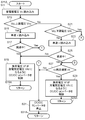
- FIG. 2A is a flowchart showing the operation of the power supply device for a vehicle according to the first embodiment.
- FIG. 2B is a flowchart showing the operation of the power supply device for a vehicle according to the first embodiment.
- FIG. 3 is a diagram showing temporal changes in voltage and vehicle speed of the power storage unit of the power supply device for a vehicle according to the first embodiment.
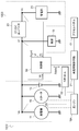
- FIG. 4 is a block circuit diagram of a power supply apparatus for a vehicle according to a second embodiment of the present invention.
- FIG. 5A is a flow chart showing the operation of the vehicular power supply device according to the second embodiment.
- FIG. 5B is a flowchart showing the operation of the vehicular power supply device in the second embodiment.
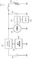
- FIG. 6 is a block circuit diagram of another vehicle power supply device in the second embodiment.
- FIG. 7 is a schematic configuration diagram of a conventional vehicle power supply
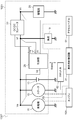
- FIG. 1 is a block circuit diagram of a vehicular power supply device 1001 according to a first embodiment of the present invention.
- an engine 15A, a generator 11, a starter 15, a main power supply 13, a vehicle control circuit 31, a load 19, and a vehicle power supply device 1001 are mounted on the vehicle 1002.
- an engine 15A, a generator 11, a starter 15, a main power supply 13, a vehicle control circuit 31, a load 19, and a vehicle power supply device 1001 are mounted on the vehicle 1002, an engine 15A, a generator 11, a starter 15, a main power supply 13, a vehicle control circuit 31, a load 19, and a vehicle power supply device 1001 are mounted.
- the generator 11 is electrically connected to the main power supply 13, the starter 15, and the load 19.
- the generator 11 generates power by being driven by the engine 15A.
- the generated electric power is generated by the electric power generated by the engine 15A consuming fuel and generated, and the kinetic energy when the vehicle 1002 is inertially traveling in a fuel cut state in which the fuel supply to the engine 15A is stopped at the time of deceleration. And regenerative power.
- the vehicle control circuit 31 injects fuel to avoid the engine stall when the vehicle speed v of the vehicle 1002 becomes less than the predetermined speed vk even during deceleration, and the engine 15A is The throttle 62 and the engine 15A are controlled to drive.
- the electric power generated by the generator 11 when the vehicle speed v is less than the predetermined speed vk is not the regenerative electric power even during deceleration.
- the predetermined speed vk is determined for each vehicle, and in the vehicle 1002 according to the first embodiment, the predetermined speed vk is 10 km / hour.
- the main power supply 13 is configured of a secondary battery such as a lead battery. Also, the starter 15 is mechanically connected to the engine 15A to start the engine 15A.
- the load 19 is an electrical component such as a navigation device, a video / audio device, and a lighting device mounted on the vehicle 1002.
- Vehicle 1002 further includes an accelerator pedal 61 and a throttle 62 both connected to vehicle control circuit 31.
- the vehicle control circuit 31 controls the opening degree of the throttle 62 according to the depression state (accelerator opening degree) of the accelerator pedal 61, and controls the amount of air and fuel supplied to the engine 15A by the throttle 62.
- Vehicle power supply device 1001 includes DC / DC converter 23, power storage unit 25, and control unit 29.
- the vehicle power supply device 1001 may further include a generator 11, a starter 15, and a main power supply 13.
- a power storage unit 25 is electrically connected to the load 19 via the DC / DC converter 23.
- DC / DC converter 23 controls charge and discharge of power storage unit 25. That is, basically, when the generator 11 generates regenerative power, the DC / DC converter 23 operates to charge the storage unit 25 with the regenerative power. When regenerative power is not generated, DC / DC converter 23 operates to discharge the regenerative power charged by power storage unit 25 to main power supply 13 and load 19 according to the state of vehicle 1002.
- power storage unit 25 stores regenerative electric power generated when vehicle 1002 decelerates. Since the regenerative power is generated sharply, in order to sufficiently store the regenerative power, power storage unit 25 is formed of a large capacity capacitor such as an electric double layer capacitor having good charge acceptance. Note that the number of electric double layer capacitors and the electrical connection method (series, parallel, series-parallel) are appropriately determined based on the power specification required for the vehicle 1002. In the first embodiment, power storage unit 25 is formed of five electric double layer capacitors having a rated voltage of 2.5 V connected in series with each other. Therefore, storage unit 25 can be charged to a storage unit voltage Vc of 12.5 V, which is the voltage across storage unit 25.
- Vc storage unit voltage
- the upper limit voltage of the storage unit voltage Vc is set as the upper limit voltage Vcu.
- storage unit 25 is discharged up to 1 V per electric double layer capacitor, that is, storage unit voltage Vc is 5 V.
- the voltage at the lower limit of storage unit voltage Vc for avoiding problems of storage unit 25 such as overdischarge is defined as lower limit voltage Vck.
- DC / DC converter 23 controls storage unit voltage Vc so that storage unit voltage Vc does not deviate from this range.
- Charge state value SOC is defined as an index indicating the amount of power stored in power storage unit 25.
- charge state value SOC is described as storage unit voltage Vc.
- Upper limit value SOCu and lower limit value SOCk of charge state value SOC will be described as upper limit voltage Vcu and lower limit voltage Vck of power storage unit voltage Vc, respectively, for vehicle power supply device 1001.
- the DC / DC converter 23 is electrically connected to the control unit 29 by signal system wiring.
- the control unit 29 is composed of a microcomputer, a memory and peripheral circuits.
- the control unit 29 controls the DC / DC converter 23 by the control signal Scont.
- the controller 29 has a voltage detection function.
- the control unit 29 is also electrically connected to the vehicle control circuit 31 by the signal system wiring.
- the vehicle control circuit 31 controls the entire vehicle 1002 and transmits signals indicating various states of the vehicle 1002 to the control unit 29 by the data signal Sdata in accordance with the vehicle communication standard, or from the control unit 29 It receives various information such as the operation status of the / DC converter 23 or the like.
- the control of the generator 11 and the starter 15 is performed by the vehicle control circuit 31, but the signal system wiring is omitted in FIG. 1 because the description of the signal system wiring is complicated. Further, the generator 11 outputs the generator voltage Va in accordance with the generated voltage command value Vg output from the vehicle control circuit 31. In the first embodiment, the generated voltage command value Vg is always 14.5V.
- FIGS. 2A and 2B are flowcharts showing the operation of the vehicular power supply device 1001.
- FIG. The flowcharts of FIGS. 2A and 2B are executed by the microcomputer operating based on the program stored in the memory of the control unit 29.
- the flowcharts of FIGS. 2A and 2B are shown as subroutines executed from the main routine. Therefore, the subroutines of FIGS. 2A and 2B are called from the main routine and executed as needed.
- control unit 29 When execution of the subroutines of FIG. 2A and FIG. 2B is started (step S11A), control unit 29 first reads storage unit voltage Vc (step S11), and then compares storage unit voltage Vc and upper limit voltage Vcu ( Step S13).
- control unit 29 stops the DC / DC converter 23 in order to prevent the storage unit 25 from being charged any more.
- control unit 29 operates DC / DC converter 23 so as to discharge power storage unit 25. The details of this operation will be described below.
- control unit 29 reads vehicle speed v of vehicle 1002 from data signal Sdata transmitted from vehicle control circuit 31 (step S15). It is determined whether or not the vehicle is decelerating (step S17). Here, the control unit 29 determines whether the vehicle 1002 is decelerating based on the difference between the read vehicle speed v and the previous vehicle speed vo, which is the previously read vehicle speed. Specifically, if the vehicle speed v is not 0 and is smaller than the previous vehicle speed vo, the control unit 29 determines that the vehicle 1002 is decelerating. If the vehicle speed v is larger than the previous vehicle speed vo, the control unit 29 determines that the vehicle 1002 is accelerating.
- the control unit 29 determines that the vehicle 1002 is traveling at a constant speed. When the vehicle speed v and the previous vehicle speed vo are both 0, the control unit 29 determines that the vehicle 1002 is at a stop.
- the determination as to whether or not the vehicle 1002 is decelerating by the control unit 29 is not limited to the method described above, and the control unit 29 determines the ratio between the vehicle speed v and the previous vehicle speed vo. Whether or not the vehicle 1002 is decelerating may be determined from the time derivative value of the vehicle speed v.
- step S17 If the vehicle 1002 is decelerating in step S17 (Yes in step S17), the generator 11 generates regenerative power when the vehicle speed v is equal to or higher than the predetermined speed vk. However, since storage unit voltage Vc is equal to or higher than upper limit voltage Vcu, storage unit 25 can not be charged with regenerative power any more. Therefore, since it is not necessary to operate the DC / DC converter 23, the control unit 29 stops the DC / DC converter 23 in order to reduce unnecessary power consumption by the DC / DC converter 23 (step S31), The process returns to the main routine (step S31A).
- step S13 when storage unit voltage Vc is higher than upper limit voltage Vcu (Yes in step S13) and vehicle 1002 is decelerating (Yes in step S17), storage unit 25 is charged with regenerative power. This is also performed when the storage unit voltage Vc reaches the upper limit voltage Vcu. That is, since storage of power storage unit 25 is limited during deceleration of vehicle 1002 to generate regenerative power, vehicle 1002 always decelerates when storage unit voltage Vc reaches upper limit voltage Vcu while storage of storage unit 25 is charging. It is inside. Therefore, when storage unit voltage Vc is equal to or higher than upper limit voltage Vcu, control unit 29 stops DC / DC converter 23 (step S31), and returns to the main routine (step S31A).
- step S17 when the vehicle 1002 is not decelerating in step S17 (No in step S17), the vehicle 1002 is accelerating, traveling at a constant speed, or stopping, that is, the vehicle 1002 is in a non-decelerating state. No regenerative power is generated during non-deceleration.
- step S17 storage unit voltage Vc is equal to or higher than upper limit voltage Vcu (Yes in step S13), and storage unit 25 is fully charged with regenerated power. ing.
- control unit 29 causes the DC / DC converter 23 to supply the regenerated power stored in the storage unit 25 to the main power supply 13 and the load 19 to effectively utilize the regenerated power and to generate the regenerated power to be generated next time. Prepare to charge as much as possible. By such an operation, high efficiency can be achieved.
- step S17 the control unit 29 controls the DC / DC converter 23 such that the load voltage Vf becomes the discharge predetermined voltage Vfd (step S19).
- discharge predetermined voltage Vfd is a voltage value set to discharge power storage unit 25 and is specifically determined as follows.
- control unit 29 In order for DC / DC converter 23 to discharge the regenerative power of power storage unit 25, control unit 29 performs DC so that load voltage Vf, which is the input / output side voltage of DC / DC converter 23, becomes higher than the current voltage value. Control the DC / DC converter 23; Thereby, DC / DC converter 23 discharges power storage unit 25 in order to raise the voltage value of current load voltage Vf to discharge predetermined voltage Vfd. Control unit 29 reads the present generated voltage command value Vg (a fixed value of 14.5 V) as data signal Sdata from vehicle control circuit 31, and adds the predetermined voltage width ⁇ Vf to the read generated voltage command value Vg to discharge Determine the default voltage Vfd.
- Vg a fixed value of 14.5 V
- the predetermined voltage width ⁇ Vf is determined in advance in consideration of the control accuracy of the DC / DC converter 23, the reading accuracy of the generator voltage Va, the load voltage Vf and the like, and in consideration of a margin.
- the control unit 29 controls the DC / DC converter 23 so that the load voltage Vf becomes the discharge predetermined voltage Vfd (step S19), whereby the load voltage Vf which is the input / output side voltage is The regenerative power stored in the storage unit 25 is discharged to be 15 V.
- the regenerative power is supplied to the main power supply 13 and the load 19, and the regenerative power can be effectively used.
- the generator 11 since a voltage higher than the generator voltage Va is applied to the generator 11, power generation in the generator 11 can be stopped.
- the generator 11 can be mechanically separated from the engine 15A, the mechanical burden on the engine 15A can be reduced accordingly, and fuel consumption can be improved.
- the same effect can be obtained by the same operation even when the vehicle is traveling at a constant speed and when the engine 15A is stopped with idling.
- the vehicle control circuit 31 performs idling stop for stopping the engine 15A while the vehicle 1002 is stopped, the generator 11 is stopped, but the generated voltage command value Vg is constant at 14.5 V.
- the control unit 29 adds the predetermined voltage width ⁇ Vf (0.5 V) to the generated voltage command value Vg (14.5 V) as described above to determine the predetermined discharge voltage Vfd as 15 V.
- the DC / DC converter 23 discharges the regenerated power stored in the storage unit 25 so that the load voltage Vf which is the input / output side voltage is 15 V, and the regenerated power is the main power supply 13 And the load 19 for effective utilization.
- control unit 29 controls DC / DC converter 23 such that load voltage Vf attains discharge predetermined voltage Vfd (step S19), thereby discharging power storage unit 25 and returning to the main routine (step S19A).
- control unit 29 compares storage unit voltage Vc with lower limit voltage Vck (step S21).
- storage unit voltage Vc is higher than lower limit voltage Vck (No in step S21), storage unit voltage Vc is between upper limit voltage Vcu and lower limit voltage Vck.
- charge and discharge control of power storage unit 25 is performed by the operation described below.
- control unit 29 reads the vehicle speed v of the vehicle 1002 (step S23), and determines whether the vehicle 1002 is decelerating in the same manner as step S17 (step S25). If vehicle 1002 is not decelerating in step S25 (No in step S25), generator 11 does not generate regenerative power, and storage unit 25 is charging the regenerative power that can be discharged, so control is performed in step S19.
- the unit 29 controls the DC / DC converter 23 so that the load voltage Vf becomes the discharge predetermined voltage Vfd.
- control unit 29 determines whether or not generator 11 generates regenerative power that can be charged by power storage unit 25. Specifically, control unit 29 compares vehicle speed v with predetermined speed vk (step S27). If the vehicle speed v is equal to or higher than the predetermined speed vk (Yes in step S27), the control unit 29 determines that regenerative electric power is generated. At the time of deceleration of the vehicle 1002 (Yes in step S25), the vehicle control circuit 31 stops the supply of fuel to the engine 15A and is in a state of fuel cut.
- the predetermined speed vk is a speed at which fuel supply to the engine 15A is started again in the fuel cut state while the vehicle 1002 is decelerating to finish the fuel cut state, and in the first embodiment, it is 10 km / hour. is there.
- the vehicle control circuit 31 injects fuel to drive the engine 15A. That is, when the vehicle speed v is equal to or higher than the predetermined speed vk in step S27 (Yes in step S27), the engine 15A is in the fuel cut state, and the power generated by the generator 11 is regenerated power.
- control unit 29 controls DC / DC converter 23 such that load voltage Vf attains charge predetermined voltage Vfc (step S29), and as a result, power storage unit 25 is charged with regenerated power.
- the charging predetermined voltage Vfc is a voltage value set to charge the storage portion 25. Specifically, it is determined as follows.
- the control unit 29 performs DC so that the load voltage Vf, which is the input / output side voltage of the DC / DC converter 23, becomes lower than the current voltage value. Control the DC / DC converter 23; Thereby, the DC / DC converter 23 charges the storage unit 25 to lower the current value of the load voltage Vf to the charge predetermined voltage Vfc.
- Control unit 29 reads the present generated voltage command value Vg (a constant value of 14.5 V) from vehicle control circuit 31, and based on the read generated voltage command value Vg, the predetermined voltage at the time of discharging of power storage unit 25 (step S19)
- the charge predetermined voltage Vfc is determined by subtracting the width ⁇ Vf. In the first embodiment, the predetermined voltage width ⁇ Vf is 0.5 V as described above.
- the predetermined voltage width ⁇ Vf is determined to be 0.5 V in any of steps S19 and S29, it may be appropriately determined in accordance with the control specification of the DC / DC converter 23 and the voltage detection accuracy.
- the predetermined voltage width ⁇ Vf is set to the same value in steps S19 and S29.
- the predetermined voltage width ⁇ Vf. May be different from each other.
- step S19 and S29 assuming that the load voltage Vf and the generator voltage Va are substantially equal, the control unit 29 adds or subtracts the predetermined voltage width ⁇ Vf to the generated voltage command value Vg to obtain the discharge predetermined voltage Vfd and the charge predetermined voltage Vfc. There is. Then, the control unit 29 controls the DC / DC converter 23 such that the load voltage Vf becomes the discharge predetermined voltage Vfd or the charge predetermined voltage Vfc. However, when the distance of the power system wiring between the generator 11 and the DC / DC converter 23 is long and the wiring resistance of the wiring becomes large, the control unit 29 sets the generated voltage command value Vg to the predetermined voltage width ⁇ Vf.
- the DC / DC converter 23 is set such that the generator voltage Va becomes the discharge predetermined voltage Vfd or the charge predetermined voltage Vfc instead of the load voltage Vf in steps S19 and S29 by adding or subtracting to determine the discharge predetermined voltage Vfd and the charge predetermined voltage Vfc. May be controlled.
- regenerative power has a large current value which changes rapidly. Therefore, when charging regenerative power to storage unit 25, load voltage Vf also fluctuates due to the wiring resistance. As a result, the control of the load voltage Vf by the DC / DC converter 23 can not catch up with the fluctuation, and there is a possibility that the regenerative power can not be recovered sufficiently.
- the generator voltage Va By controlling the generator voltage Va by the DC / DC converter 23, the influence of the voltage fluctuation due to the wiring resistance can be reduced, and the regenerative power can be recovered sufficiently and the storage portion 25 can be charged.
- step S27 When the vehicle speed v is smaller than the predetermined speed vk in step S27 (No in step S27), the vehicle 1002 ends the fuel cut state as described above, and the vehicle control circuit 31 supplies fuel to drive the engine 15A. If the power generated by the generator 11 is charged to the storage unit 25 in this state, the charging operation involves the consumption of fuel, and the efficiency is reduced. Therefore, when vehicle speed v is smaller than predetermined speed vk in step S27 (No in step S27), control unit 29 controls DC / DC converter 23 to stop to stop charging of power storage unit 25 (step S31) Return to the main routine (step S31A). As a result, unnecessary operation of the DC / DC converter 23 is not performed, and accordingly, high efficiency can be achieved.
- control unit 29 controls DC / DC converter 23 so as not to discharge from storage unit 25 any more. Specifically, first, the control unit 29 reads the vehicle speed v (step S33), and determines whether the vehicle 1002 is decelerating in the same manner as in steps S17 and S25 (step S35). If the vehicle 1002 is decelerating in step S35 (Yes in step S35), the control unit 29 performs the operations in and after step S27 described above.
- step S35 if vehicle 1002 is decelerating in step S35 (Yes in step S35), if the vehicle speed v is equal to or higher than the predetermined speed vk (Yes in step S27), the regenerative power can be collected and the power storage unit 25 is charged.
- the DC / DC converter 23 is controlled to do this (step S29). If vehicle 1002 is decelerating in step S35 (Yes in step S35), storage unit voltage Vc reaches lower limit voltage Vck when vehicle speed v is less than predetermined speed vk (No in step S27). Therefore, control unit 29 stops the operation of DC / DC converter 23 so as not to discharge from power storage unit 25 (step S31), and returns to the main routine (step S31A).
- control unit 29 controls DC / DC converter 23 to charge regenerative power to storage unit 25 (step S29). Or the DC / DC converter 23 is stopped (step S31), the storage unit 25 is not further discharged.
- step S35 when the vehicle 1002 is not decelerating in step S35 (No in step S35), the vehicle 1002 is in a non-decelerating state, and in this state, the control unit 29 compares the vehicle speed v with the predetermined speed vk (step S37). If it is determined in step S37 that the vehicle speed v is smaller than the predetermined speed vk (No in step S37), the vehicle 1002 is stopping, accelerating, or traveling at an extremely low speed lower than the predetermined speed vk. Therefore, regenerative electric power to be charged by power storage unit 25 is not generated. Furthermore, since storage unit voltage Vc is equal to or lower than lower limit voltage Vck, storage unit 25 can not discharge any more. As described above, since the charge / discharge to the storage unit 25 is not performed, the control unit 29 controls the DC / DC converter 23 to stop (step S31), and returns to the main routine (step S31A).
- step S37 if it is determined in step S37 that the vehicle speed v is equal to or higher than the predetermined speed vk (Yes in step S37), the vehicle 1002 is accelerating or traveling at a predetermined speed vk. At this time, since storage unit voltage Vc is equal to or lower than lower limit voltage Vck, storage unit 25 is not discharged, but storage unit 25 can be charged when regenerative power is generated. However, since it is not known when the regenerative power is generated, it is necessary to start the DC / DC converter 23 to operate and to be in the standby state before the regenerative power is generated. The operation of the vehicle power supply device 1001 at that time will be described.
- control unit 29 reads the state of the accelerator pedal based on data signal Sdata transmitted from vehicle control circuit 31 (step S39).
- step S39 When the accelerator pedal is depressed and the vehicle 1002 continues to accelerate and drive at a constant speed, regenerative electric power is not generated. Therefore, when the state of the accelerator pedal read in step S39 is not the state of accelerator off (No in step S41), storage unit 25 is in a state where neither charging nor discharging is performed. Control is stopped (step S31), and the process returns to the main routine (step S31A).
- storage unit voltage Vc is less than upper limit voltage Vcu (No in step S13), storage unit voltage Vc is less than lower limit voltage Vck (Yes in step S21), and vehicle 1002 is in a non-decelerating state (step In the above operation when the vehicle speed v is less than the predetermined speed vk (No in S35) (No in step S37 or No in step S41), regenerative power is discharged from power storage unit 25 and storage unit voltage Vc is lower limit voltage Vck.
- step S37 if the vehicle speed v is equal to or higher than the predetermined speed vk, the vehicle 1002 is accelerating or traveling at a constant speed, so the probability of being in the accelerator on state where the throttle 62 is opened by depressing the accelerator pedal 61 is very high. high.
- step S41 if the vehicle 1002 is in the accelerator-off state in step S41 (Yes in step S41), the driver is not depressing the accelerator pedal while the vehicle 1002 is accelerating or traveling at a constant speed. In this case, there is a possibility that the driver depresses and decelerates the brake pedal immediately after that, so the control unit 29 activates the DC / DC converter 23 to be in a standby state. Thereby, even when the driver depresses the brake pedal, the regenerative electric power can be recovered without being dropped and the power storage unit 25 can be charged.
- the specific operation of the vehicle power supply device 1001 at this time will be described below.
- step S41 When vehicle 1002 is in the accelerator off state in step S41 (Yes in step S41), storage unit voltage Vc is equal to or lower than lower limit voltage Vck, and control unit 29 does not discharge storage unit 25. Control 23 Furthermore, at this time, it is unclear whether or not the driver decelerates the vehicle 1002 based on a clear intention that the driver depresses the brake pedal, and therefore the control unit 29 does not charge the storage unit 25 either. Control. Although the vehicle decelerates gently while the vehicle 1002 is in inertial travel, recovering the regenerative power in this state and charging the storage unit 25 shortens the inertial travel distance, and it may be overall depending on conditions such as the vehicle speed v and the vehicle weight. Fuel consumption may not improve.
- control unit 29 operates DC / DC converter 23 such that power storage unit 25 hardly charges and discharges, and puts DC / DC converter 23 in a standby state.
- control unit 29 reads the current voltage value of storage unit voltage Vc, controls DC / DC converter 23 to maintain the voltage value (step S43), and returns to the main routine (step S43A).
- the control unit 29 can operate the DC / DC converter 23.
- step S43 the DC / DC converter 23 controls so as to maintain the storage unit voltage Vc, and does not control the load voltage Vf which is an input / output side voltage.
- control unit 29 After returning to the main routine in steps S19A, S29A, S31A, and S43A, the control unit 29 starts to execute the subroutines shown in FIGS. 2A and 2B again (step S11A), and repeatedly executes the subroutines in this manner.
- control unit 29 can switch between charge / discharge, stop, and standby of storage unit 25 of DC / DC converter 23 according to storage unit voltage Vc and the state of vehicle 1002.
- vehicle speed v is equal to or higher than predetermined speed vk and vehicle 1002 is in the accelerator off state when vehicle 1002 is not decelerating, or storage unit voltage Vc is larger than lower limit voltage Vck.
- the control unit 29 operates the DC / DC converter 23.
- Storage unit voltage Vc corresponds to a charge state value SOC of storage unit 25.
- Lower limit voltage Vck corresponds to lower limit value SOCk of charge state value SOC.
- the operation of the DC / DC converter 23 includes the standby in step S43, that is, the state where the DC / DC converter 23 is not stopped.
- control unit 29 controls DC / DC converter 23 to discharge power storage unit 25 (step S19). At this stage, control unit 29 controls DC / DC converter 23 Is operating.
- control unit 29 when storage unit voltage Vc is equal to or higher than lower limit voltage Vck, control unit 29 operates DC / DC converter 23 if vehicle 1002 is in a non-decelerating state. On the other hand, storage unit voltage Vc is lower than lower limit voltage Vck and vehicle 1002 is not decelerating (No in step S35) and vehicle speed v is over predetermined speed vk (Yes in step S37). If it is in the off state (Yes in step S41), the control unit 29 operates the DC / DC converter 23 in the standby state (step S43). As described above, when the vehicle speed v is the predetermined speed vk or more and the vehicle 1002 is in the accelerator-off state when the vehicle 1002 is not decelerating, the control unit 29 operates the DC / DC converter 23.
- control unit 29 operates DC / DC converter 23 to discharge power storage unit 25.
- control unit 29 operates DC / DC converter 23 to charge power storage unit 25 in step S29.
- Upper limit voltage Vcu corresponds to upper limit value SOCu of charge state value SOC. At this time, the DC / DC converter 23 has already been activated. This is due to the following reason.
- step S25 When storage unit voltage Vc is between upper limit voltage Vcu and lower limit voltage Vck and vehicle 1002 is decelerating (Yes in step S25), DC / DC converter 23 charges regenerative power to storage unit 25.
- the controller 29 operates the DC / DC converter 23. Therefore, when storage unit voltage Vc is between upper limit voltage Vcu and lower limit voltage Vck and vehicle 1002 is decelerating (Yes in step S25), control unit 29 operates DC / DC converter 23 without fail.
- step S35 when the result of step S35 is Yes, storage unit voltage Vc is equal to or lower than lower limit voltage Vck, and vehicle 1002 is decelerating. Therefore, the DC / DC converter 23 is just before starting to charge the storage unit 25. In order to charge regenerative power to storage unit 25, vehicle 1002 needs to be in deceleration, so the driver does not step on accelerator pedal 61. After that, no matter how suddenly the driver steps on the brake pedal, the processing speed of the control unit 29 is much faster than the speed at which the brake pedal is depressed, so the vehicle 1002 decelerates in step S35 (step S35). If the accelerator is off at step S41 (Yes at step S41), the control unit 29 operates the DC / DC converter 23 at step S43 and is in a standby state.
- FIG. 3 is a diagram showing changes in storage unit voltage Vc and vehicle speed v with respect to time.
- the horizontal axis indicates time t.
- the vertical axis of the upper diagram of FIG. 3 indicates the storage unit voltage Vc, and the vertical axis of the lower diagram indicates the vehicle speed v.
- the vehicle 1002 is provided with an idling stop function.
- step S19 control unit 29 performs DC / DC control so that load voltage Vf becomes discharge predetermined voltage Vfd.
- the converter 23 is controlled.
- the power of storage unit 25 is partially discharged to main power supply 13 by DC / DC converter 23 and the rest is discharged to load 19, so that storage unit voltage Vc decreases with time.
- control unit 29 controls DC / DC converter 23 such that load voltage Vf attains charge predetermined voltage Vfc, that is, controls DC / DC converter 23 so as to charge regenerative power to storage unit 25. .
- storage unit voltage Vc rises.
- storage unit voltage Vc which has started to rise from time t1, reaches upper limit voltage Vcu at time t2 and becomes higher than upper limit voltage Vcu.
- the results of steps S13 and S17 in the flowcharts of FIG. 2A and FIG. 2B become Yes, so the control unit 29 stops the DC / DC converter 23 in step S31.
- the storage unit 25 can not be charged with the regenerative electric power any more, and since it is decelerating, the storage unit 25 is not discharged. Therefore, in order to reduce unnecessary power consumption of the DC / DC converter 23, the control unit 29 stops the DC / DC converter 23.
- control unit 29 controls DC / DC converter so that the load voltage Vf becomes the discharge predetermined voltage Vfd in step S19.
- control unit 29 controls DC / DC converter 23 to discharge the regenerative power of power storage unit 25 mainly to load 19. That is, when the deceleration of the vehicle 1002 ends (time t3), the control unit 29 activates and operates the DC / DC converter 23 stopped at time t2.
- storage unit voltage Vc decreases with time from time t3. In this manner, storage unit voltage Vc reaching upper limit voltage Vcu quickly drops, and storage unit 25 is quickly discharged, and the regenerative power generated next time can be recovered as much as possible and stored in storage unit 25.
- control unit 29 controls the DC / DC converter 23 such that the load voltage Vf becomes the discharge predetermined voltage Vfd in step S19. Do. As a result, control unit 29 continues the operation of mainly discharging the regenerative power of power storage unit 25 to load 19. As a result, storage unit voltage Vc decreases with time.
- control unit 29 causes load voltage Vf to be discharge predetermined voltage Vfd. Control the DC / DC converter 23. As a result, control unit 29 further continues the operation of mainly discharging the regenerative power of power storage unit 25 to load 19. As a result, storage unit voltage Vc decreases with time.
- step S13 the result of step S21 is Yes, the result of step S35 is No, the result of step S37 is Yes, and the result of step S41 is It becomes No.
- control unit 29 performs control to stop DC / DC converter 23 in order to stop charging of power storage unit 25.
- power storage unit 25 can not discharge any more, and since it is traveling at a constant speed, regenerative power is not generated, and power storage unit 25 is not charged. Therefore, in order to reduce unnecessary power consumption of the DC / DC converter 23, the control unit 29 stops the DC / DC converter 23.
- control unit 29 controls DC / DC converter 23 to charge electric storage unit 25 with the regenerative electric power.
- the control unit 29 stops the DC / DC converter 23 from time t5 to immediately before time t7. Therefore, control unit 29 operates to control DC / DC converter 23 at time t7 as follows in order to charge storage unit 25 so as not to lose the regenerative power.
- step S13 in the flowchart of FIGS. 2A and 2B.
- step S21 becomes Yes
- step S35 becomes No
- step S37 becomes Yes
- step S41 becomes Yes
- step S43 control unit 29 determines the current power storage unit The voltage value of the voltage Vc is read, and the DC / DC converter 23 is controlled to maintain the voltage value.
- control unit 29 controls DC / DC converter 23 to maintain current storage unit voltage Vc (here, equal to lower limit voltage Vck), DC / DC converter 23 hardly flows current, although DC / DC converter 23 The DC converter 23 has completed startup and is operating in a standby state.
- step S13 the result of step S13 is No
- the result of step S21 is Yes
- the result of step S35 is Yes
- the result of S27 is Yes. Therefore, in step S29, the control unit 29 controls the DC / DC converter 23 such that the load voltage Vf becomes equal to the charge predetermined voltage Vfc. As a result, the storage unit 25 can be charged without losing regenerative power by the DC / DC converter 23 that has already started.
- control unit 29 stops DC / DC converter 23 in order to stop charging of storage unit 25 in step S31. Control. This is because the storage unit 25 can not be charged any more and is decelerating, so that the storage unit 25 is not discharged. Therefore, in order to reduce unnecessary power consumption of the DC / DC converter 23, the control unit 29 stops the DC / DC converter 23.
- the vehicle speed v of the decelerating vehicle 1002 reaches the predetermined speed vk at time t9 and falls below the predetermined speed vk.
- the storage unit voltage Vc remains at the upper limit voltage Vcu at this time, the results of steps S13 and S17 become Yes in the flowcharts of FIGS. 2A and 2B, and the DC / DC converter 23 continues to be stopped in step S31. It becomes.
- control unit 29 controls DC / DC converter 23 to mainly supply the regenerative power stored in power storage unit 25 to load 19. That is, at time t10, similarly to time t3, the result in step S13 is Yes in the flowcharts of FIGS. 2A and 2B, and the result in step S17 is No. In step S19, control unit 29 controls load voltage Vf to be discharge predetermined voltage Vfd.
- step S13 the result of step S21 is Yes
- step S35 the result of step S35
- step S37 the controller 29 stops the DC / DC converter 23 in step S31. That is, storage unit voltage Vc reaches lower limit voltage Vck and is lower than or equal to lower limit voltage Vck, and storage unit 25 can not be discharged any more.
- the control unit 29 stops the DC / DC converter 23. Since discharge from power storage unit 25 is stopped at time t11, electric power is supplied from main power supply 13 to load 19 after time t11 in the idling stop state.
- the driver changes the brake pedal to the accelerator pedal 61 to start accelerating the vehicle 1002.
- the vehicle control circuit 31 detects a change in pressure from the brake pedal to the accelerator pedal 61, drives the starter 15 to start the engine 15A, and as a result, the idling stop is finished.
- the vehicle speed v rises as shown in FIG.
- storage unit voltage Vc reaches lower limit voltage Vck at time t11
- storage unit 25 can not be discharged.
- the vehicle 1002 is accelerated at time t12 and no regenerative power is generated, charging of power storage unit 25 can not be performed.
- the vehicle speed v is smaller than the predetermined speed vk.
- step S13 is No
- the result of step S21 is Yes
- the result of step S35 is No
- the result of step S37 is No.
- the control unit 29 stops the DC / DC converter 23.
- step S13 the result of step S13 is No
- the result of step S21 is Yes
- the result of step S35 is No
- the result of step S37 is Yes.
- the result of step S41 is No. Therefore, the control unit 29 continues to stop the DC / DC converter 23 in step S31.
- step S13 is No
- the result of step S21 is Yes
- the result of step S35 is No
- the result of step S37 is Yes
- the result of step S41 is No, which is the same state as at time t13. Therefore, the control unit 29 continues to stop the DC / DC converter 23 in step S31.
- control unit 29 reads the current voltage value of storage unit voltage Vc in step S43.
- the DC / DC converter 23 is controlled to maintain the voltage value, and the DC / DC converter 23 is operated in the standby state.
- the control unit 29 controls the DC / DC converter 23 so that the load voltage Vf becomes the charge predetermined voltage Vfc in step S29, and regenerative electric power generated by deceleration. Control the DC / DC converter 23 to charge the storage unit 25. As a result, storage unit voltage Vc rises with time.
- control unit 29 controls DC / IR to stop charging of power storage unit 25 in step S31.
- Control is performed to stop the DC converter 23. This is because the storage unit 25 can not be charged any more and is decelerating, so that the storage unit 25 is not discharged. Therefore, in order to reduce unnecessary power consumption of the DC / DC converter 23, the control unit 29 stops the DC / DC converter 23.
- control unit 29 controls DC / DC converter 23 so that the regenerative power stored in power storage unit 25 is mainly discharged to load 19 until time t16.
- the control unit 29 causes the load voltage Vf to be the discharge predetermined voltage Vfd.
- the DC / DC converter 23 is controlled. This operation is the same operation as time t3 at which the DC / DC converter 23 is activated when the deceleration of the vehicle 1002 ends. Thereby, effective utilization of regenerative power can be achieved.
- the efficiency of the vehicle 1002 can be improved by repeating any of the above-described operations according to the situation.
- the DC / DC converter 141 may be controlled to be stopped in a period during which it operates only to maintain the voltage of the electric double layer capacitor 143. In this case, even if the DC / DC converter 141 is operated after the generation of the regenerative power, the regenerative power may not be recovered until the start is completed. In particular, if it is not possible to recover the regenerative power that occurs sharply immediately after the start of deceleration by braking, the recovery efficiency of the regenerative power is reduced.
- control unit 29 operates to stop DC / DC converter 23 when storage unit voltage Vc is higher than upper limit voltage Vcu or lower than lower limit voltage Vck. However, when the condition for operating the DC / DC converter 23 is satisfied simultaneously even when the condition for stopping is satisfied, the control unit 29 gives priority to the operation of the DC / DC converter 23.
- the conditions for operating the DC / DC converter 23 are: 1) the vehicle speed v is equal to or higher than the predetermined speed vk when the vehicle 1002 is not decelerating, and the engine 15A of the vehicle 1002 is in the accelerator off state; This is the case where either Vc (corresponding to the state of charge value SOC) is larger than the lower limit voltage Vck (corresponding to the lower limit value SOCk) and the deceleration of the vehicle 1002 ends.
- the control unit 29 gives priority to the activation of the DC / DC converter 23 over the stop of the DC / DC converter 23. This is not limited to such control, and when storage unit voltage Vc rises and reaches upper limit voltage Vcu in the flowcharts of FIGS.
- control unit 29 may immediately stop the DC / DC converter 23. In this case, the DC / DC converter 23 can be stopped for as many periods as possible. However, immediately after that, if the above condition for starting up the DC / DC converter 23 is satisfied, the DC / DC converter 23 will be started up immediately after the stop, and a period in which the startup is completed is required. Therefore, in vehicle power supply device 1001 according to the first embodiment, control unit 29 sets the condition for stopping DC / DC converter 23 (for example, in the case where state of charge SOC is equal to or less than predetermined lower limit value SOCk). The control unit 29 operates the DC / DC converter 23 without stopping it even if the condition for activating at the same time is satisfied.
- control unit 29 operates to stop DC / DC converter 23 when storage unit voltage Vc is higher than upper limit voltage Vcu or lower than lower limit voltage Vck. .
- Control unit 29 controls DC / DC converter 23 to maintain storage unit voltage Vc without stopping DC / DC converter 23 when storage unit voltage Vc is equal to or higher than upper limit voltage Vcu. It is also good. This is due to the following reason. When storage unit voltage Vc rises and reaches upper limit voltage Vcu and DC / DC converter 23 is stopped, storage unit voltage Vc gradually decreases due to the internal resistance of storage unit 25.
- control unit 29 may operate DC / DC converter 23 to maintain storage unit voltage Vc when storage unit voltage Vc is equal to or higher than upper limit voltage Vcu.
- control unit 29 may stop DC / DC converter 23 to reduce the power consumption, which may lead to an improvement in efficiency. . Therefore, in consideration of the internal resistance of storage unit 25 used and the stop period of DC / DC converter 23 during use of vehicle 1002, DC / DC converter 23 in the case where storage unit voltage Vc is higher than upper limit voltage Vcu.
- control unit 29 operates to stop DC / DC converter 23 when storage unit voltage Vc (corresponding to state of charge value SOC) reaches at least lower limit voltage Vck (corresponding to lower limit value SOCk). .
- control unit 29 activates DC / DC converter 23 with vehicle speed v equal to or higher than predetermined speed vk and vehicle 1002 in an accelerator-off state when vehicle 1002 is not decelerating. There is. This operation is not limited to when the vehicle 1002 is not decelerating. That is, in FIG. 2A and FIG. 2B, when the vehicle 1002 is not decelerating as the first condition, the results of steps S17, S25, and S35 correspond to No. In these cases, the control unit 29 operates the DC / DC converter 23. On the other hand, the operation of the vehicular power supply device 1001 when the results of steps S17, S25, and S35 are Yes will be described.
- control unit 29 stops the DC / DC converter 23 in step S31.
- control unit 29 is not limited to the operation of stopping DC / DC converter 23, and storage unit An operation of maintaining the voltage Vc may be performed. In this case, the DC / DC converter 23 is operating.
- step S27 If the result of steps S25 and S35 is Yes, if the vehicle speed v is equal to or higher than the predetermined speed vk in step S27 (Yes in step S27), the control unit 29 controls the load voltage Vf to be a predetermined charge voltage in step S29.
- the DC / DC converter 23 is controlled to have Vfc. That is, the DC / DC converter 23 is operating.
- the conditions under which the DC / DC converter 23 operates are not limited when the vehicle 1002 is not decelerating.
- one of the conditions for operating the DC / DC converter 23 is that the vehicle 1002 is in the accelerator off state, but this is limited to the accelerator off state. It is not a thing. That is, the state of the accelerator pedal 61 is determined by the accelerator opening degree signal indicating the accelerator opening degree among the data signals Sdata transmitted from the vehicle control circuit 31. In the first embodiment, the accelerator off state is determined from the accelerator opening signal when the driver releases his or her foot from the accelerator pedal 61. However, even when the driver puts his foot on the accelerator pedal 61, there is a region where the vehicle control circuit 31 does not judge that the accelerator pedal 61 is depressed. In addition, there may be an error due to the play of the accelerator pedal 61. Even in these states, by performing the same control as in the accelerator off state, the control unit 29 increases the frequency with which the DC / DC converter 23 is operated in the standby state, thereby further reducing the possibility of dropping the regenerative power.
- the control unit 29 may determine that the result of step S41 in FIG. 2A and FIG. 2B is Yes if the accelerator opening degree is equal to or less than the predetermined accelerator opening degree, including the accelerator off.
- the predetermined accelerator opening degree is obtained in advance as an accelerator opening degree equivalent to the accelerator off state, including an area where the depression of the accelerator pedal 61 is not determined as described above and an error due to play. It is stored in the control unit 29.
- the accelerator opening degree is not limited to the configuration determined by the accelerator opening degree signal, and may be determined by a throttle opening degree signal obtained according to the accelerator opening degree signal.
- FIG. 4 is a block circuit diagram of a vehicular power supply device 1003 in the second embodiment.
- 5A and 5B are flowcharts showing the operation of the vehicular power supply device 1003.
- FIG. 4 the same parts as those of the vehicle power supply device 1001 in the first embodiment shown in FIGS. 1, 2A and 2B are designated by the same reference numerals.
- the vehicle power supply device 1003 according to the second embodiment includes a control unit 89 instead of the control unit 29 of the vehicle power supply device 1001 shown in FIG.
- charge state value SOC storage unit voltage Vc
- SOCk lower limit voltage Vck
- vehicle 1002 is decelerating and vehicle speed v is less than predetermined speed vk.
- the control unit 89 operates the DC / DC converter 23. Details of the operation of the vehicular power supply device 1003 will be described with reference to FIGS. 5A and 5B.
- control unit 89 determines vehicle speed v and predetermined speed vk. Are compared (step S51). If vehicle speed v is equal to or higher than predetermined speed vk in step S51 (Yes in step S51), storage unit 25 is in a fully charged state although deceleration is in progress. The unit 89 controls the DC / DC converter 23 to stop. This operation is the same as that of the first embodiment.
- step S51 if the vehicle speed v is less than the predetermined speed vk in step S51 (No in step S51), the vehicle 1002 is about to stop since the vehicle is decelerating and the vehicle speed v is small.
- control unit 29 in the first embodiment stops DC / DC converter 23, but control unit 89 in the second embodiment operates DC / DC converter 23 to discharge power storage unit 25 in step S19. .
- power storage unit 25 is discharged.
- the regenerative power stored in power storage unit 25 can be discharged as quickly as possible, so that the regenerative power to be generated later can be collected as much as possible and stored in power storage unit 25.
- step S25 the controller 89 sets the vehicle speed v to a predetermined speed. It compares with vk (step S27). If vehicle speed v is equal to or higher than predetermined speed vk in step S27 (Yes in step S27), control unit 89 charges regenerative power to storage unit 25 in step S29 as in control unit 29 in the first embodiment.
- the DC / DC converter 23 is operated.
- step S27 if the vehicle speed v is less than the predetermined speed vk in step S27 (No in step S27), the vehicle 1002 is about to stop since the vehicle is decelerating and the vehicle speed v is small. Therefore, also in this case, by discharging power storage unit 25 as much as possible, it is possible to recover a large amount of regenerative power generated later.
- control unit 29 stops DC / DC converter 23 in step S31.
- control unit 89 discharges storage unit 25 in step S19 if storage unit voltage Vc is larger than lower limit voltage Vck and vehicle speed v is lower than predetermined speed vk during deceleration.
- the DC / DC converter 23 is operated. Therefore, although DC / DC converter 23 may be operated or stopped under the above conditions, DC / DC converter 23 is operated in vehicle power supply device 1003 in the second embodiment to store power storage unit 25. By discharging, it is possible to obtain an effect that even a little more regenerative electric power can be recovered than the vehicle power supply device 1001 according to the first embodiment.
- control unit 29 determines vehicle speed v and predetermined speed vk in step S27. Compare with. However, if vehicle speed v is less than predetermined speed vk in vehicle power supply device 1003 in the second embodiment (No at step S27), storage unit voltage Vc is lower than lower limit voltage Vck. Regardless, the power storage unit 25 is discharged in step S19.
- control unit 89 determines the vehicle speed v to be set in step S53.
- control unit 89 controls DC / DC converter 23 in step S29 to charge regenerative power in power storage unit 25 as in the first embodiment. To operate. On the other hand, if the vehicle speed v is less than the predetermined speed vk in step S53 (No in step S53), the control unit 89 stops the DC / DC converter 23 in step S31 to perform the same operation as in the first embodiment. Thereby, it is possible to prevent further discharge from the storage unit 25 of the storage unit voltage Vc which has become lower than or equal to the lower limit voltage Vck, and to stop the unnecessary operation of the DC / DC converter 23.
- the remaining operations of the vehicle power supply device 1003 according to the second embodiment are the same as those of the first embodiment.
- control units 29 and 89 control DC / DC if the vehicle speed v is equal to or higher than the predetermined speed vk and the accelerator is off when the vehicle 1002 is not decelerating.
- the converter 23 is operated in the standby state, and the DC / DC converter 23 is operated so as to charge the storage unit 25 with regenerative power at the start of deceleration of the vehicle 1002.
- control units 29 and 89 do not operate DC / DC converter 23 in the standby state, and vehicle speed v is equal to or greater than predetermined speed vk when vehicle 1002 is decelerated.
- the DC / DC converter 23 may be operated to control the DC / DC converter 23 so as to charge the power storage unit 25 with the power from the generator 11.
- the driver changes the accelerator pedal 61 to the brake pedal very quickly, it is possible to reduce the loss of regenerative electric power generated during that time.
- the driver changes the accelerator pedal 61 to the brake pedal relatively slowly so that DC / DC does not step on the brake pedal yet and the vehicle 1002 is in a gentle deceleration state while inertially traveling.
- DC converter 23 charges power storage unit 25 with power.
- the control units 29 and 89 select whether to operate the DC / DC converter 23 in a standby state.
- control units 29 and 89 control DC / DC converter 23 so as to maintain current storage unit voltage Vc.
- the control units 29 and 89 may control the DC / DC converter 23 such that the load voltage Vf becomes the generator voltage Va. That is, if load voltage Vf and generator voltage Va are approximately equal, no current flows between the input and output of DC / DC converter 23, so charging / discharging of power storage unit 25 is hardly performed and DC / DC converter 23 is in a standby state.
- control units 29 and 89 are stable. It is desirable to control the DC / DC converter 23 to operate in the standby state so as to maintain the existing storage unit voltage Vc. Further, the control units 29 and 89 can also suppress the overdischarge of the storage unit 25 by controlling the DC / DC converter 23 so as to maintain the storage unit voltage Vc.
- FIG. 6 is a block circuit diagram of another vehicle power supply device 1004 in the second embodiment. 6, the same reference numerals as in FIG. 1 denote the same parts in FIG.
- Vehicle power supply device 1004 further includes a current sensor 90 that detects the current flowing between the input and output of DC / DC converter 23.
- the control units 29 and 89 may control the DC / DC converter 23 so that no current flows between the input and output of the DC / DC converter 23. In this case, the control units 29 and 89 can maintain the operation of the DC / DC converter 23 in the standby state with high accuracy so as not to charge and discharge the storage unit 25.
- the current sensor 90 is required, the required accuracy An optimal configuration can be selected appropriately according to the specification.
- control units 29 and 89 determine whether vehicle 1002 is decelerating based on a comparison between vehicle speed v and previous vehicle speed vo, but the present invention is limited thereto. It is not a thing.
- the control units 29 and 89 may determine whether the vehicle 1002 is decelerating based on a brake signal output from the vehicle control circuit 31 when the brake pedal is depressed. In this case, it can be easily determined whether or not the vehicle 1002 is decelerating, but the regenerative power can not be recovered unless the brake pedal is depressed. Therefore, when the driver operates the transmission to shift to low gear and decelerates the vehicle 1002 without stepping on the brake pedal, the generated regenerative electric power is discarded as heat. Therefore, it is desirable that the control units 29 and 89 in the first and second embodiments determine whether the vehicle 1002 is decelerating based on the comparison between the vehicle speed v and the previous vehicle speed vo.
- the control units 29 and 89 compare the vehicle speed v of the vehicle 1002 with the predetermined speed vk.
- the predetermined speed vk is a speed at which the fuel cut ends when the engine 15A decelerates, as described above.
- the vehicle control circuit 31 outputs a fuel cut signal when the fuel cut is performed, and ends the output of the fuel cut signal when the fuel cut is finished. Based on the fuel cut signal, the control units 29 and 89 may determine that the vehicle speed v has dropped to the predetermined speed vk when the vehicle control circuit 31 has finished outputting the fuel cut signal.
- control units 29 and 89 set discharge predetermined voltage Vfd and charge predetermined voltage Vfc as target voltages.
- the DC / DC converter 23 is controlled.
- the discharge predetermined voltage Vfd and the charge predetermined voltage Vfc may be set to the same constant voltage (for example, 14.5 V), and the control units 29 and 89 may change the generated voltage command value Vg output to the generator 11. This operation is specifically described below.
- the vehicle control circuit 31 outputs the generated voltage command value Vg to the generator 11 so as to raise the generator voltage Va to, for example, 15V.
- DC / DC converter 23 operates to lower load voltage Vf (or generator voltage Va) to 14.5 V, so that generated regenerative power can be charged to storage unit 25.
- vehicle control circuit 31 reduces generated voltage command value Vg from 14.5 V and outputs it to generator 11 as 14 V, for example.
- DC / DC converter 23 operates to raise load voltage Vf or generator voltage Va to 14.5 V, so that the regenerative power stored in power storage unit 25 can be discharged to load 19 or main power supply 13.
- the electric double layer capacitor is used for storage unit 25.
- another capacitor such as an electrochemical capacitor may be used.
- storage unit 25 may be a secondary battery other than a capacitor
- charge state value SOC indicating the power stored by the secondary battery is not proportional to storage unit voltage Vc.
- the storage unit voltage Vc can not be used as the charge state value SOC.
- vehicle power supply devices 1001, 1003 and 1004 further include a current sensor for detecting the current flowing in power storage unit 25 formed of a secondary battery.
- Control units 29 and 89 time-integrate the current flowing through power storage unit 25 to determine charge state value SOC.
- charge state value SOC When a secondary battery is used for power storage unit 25, upper limit value SOCu and lower limit value SOCk of charge state value SOC of the secondary battery need to be obtained in advance.
- the current sensor 90 of the vehicle power supply 1004 shown in FIG. 6 directly detects the current flowing between the input and output of the DC / DC converter 23, and the control units 29, 89 prevent the DC / DC converter 23 from flowing. Control.
- the vehicle power supply device can achieve high efficiency by reducing the power consumption of the DC / DC converter while maintaining the recovery efficiency of regenerative power, and in particular, as a power supply device for vehicles with regenerative power recovery function It is useful.
Landscapes
- Engineering & Computer Science (AREA)
- Power Engineering (AREA)
- Mechanical Engineering (AREA)
- Transportation (AREA)
- Sustainable Energy (AREA)
- Life Sciences & Earth Sciences (AREA)
- Sustainable Development (AREA)
- Chemical & Material Sciences (AREA)
- Combustion & Propulsion (AREA)
- Automation & Control Theory (AREA)
- Electric Propulsion And Braking For Vehicles (AREA)
- Charge And Discharge Circuits For Batteries Or The Like (AREA)
- Control Of Charge By Means Of Generators (AREA)
Abstract
Priority Applications (4)
| Application Number | Priority Date | Filing Date | Title |
|---|---|---|---|
| CN201180037849.0A CN103052527B (zh) | 2010-08-02 | 2011-07-11 | 车辆用电源装置 |
| US13/808,609 US8768554B2 (en) | 2010-08-02 | 2011-07-11 | Vehicle power source device |
| EP11814242.1A EP2602148A4 (fr) | 2010-08-02 | 2011-07-11 | Dispositif de source d'alimentation de véhicule |
| JP2012527573A JP5691022B2 (ja) | 2010-08-02 | 2011-07-11 | 車両用電源装置 |
Applications Claiming Priority (2)
| Application Number | Priority Date | Filing Date | Title |
|---|---|---|---|
| JP2010-173357 | 2010-08-02 | ||
| JP2010173357 | 2010-08-02 |
Publications (1)
| Publication Number | Publication Date |
|---|---|
| WO2012017602A1 true WO2012017602A1 (fr) | 2012-02-09 |
Family
ID=45559128
Family Applications (1)
| Application Number | Title | Priority Date | Filing Date |
|---|---|---|---|
| PCT/JP2011/003953 Ceased WO2012017602A1 (fr) | 2010-08-02 | 2011-07-11 | Dispositif de source d'alimentation de véhicule |
Country Status (5)
| Country | Link |
|---|---|
| US (1) | US8768554B2 (fr) |
| EP (1) | EP2602148A4 (fr) |
| JP (1) | JP5691022B2 (fr) |
| CN (1) | CN103052527B (fr) |
| WO (1) | WO2012017602A1 (fr) |
Cited By (6)
| Publication number | Priority date | Publication date | Assignee | Title |
|---|---|---|---|---|
| WO2014064762A1 (fr) * | 2012-10-23 | 2014-05-01 | 三菱電機エンジニアリング株式会社 | Dispositif de commande de source de puissance et procédé de commande du dispositif de commande de source de puissance |
| JP2015009791A (ja) * | 2013-07-02 | 2015-01-19 | 本田技研工業株式会社 | 車両用電源装置 |
| JP2015012684A (ja) * | 2013-06-28 | 2015-01-19 | 三洋電機株式会社 | 電源装置 |
| WO2015190094A1 (fr) * | 2014-06-11 | 2015-12-17 | 川崎重工業株式会社 | Système de stockage d'énergie électrique et son procédé de commande |
| JP2016002857A (ja) * | 2014-06-17 | 2016-01-12 | 株式会社豊田自動織機 | 車両の電源装置 |
| JP2016097768A (ja) * | 2014-11-20 | 2016-05-30 | トヨタ自動車株式会社 | 車両の駆動制御装置 |
Families Citing this family (12)
| Publication number | Priority date | Publication date | Assignee | Title |
|---|---|---|---|---|
| US9041329B2 (en) * | 2012-09-19 | 2015-05-26 | Ford Global Technologies, Llc | Vehicle electric machine control strategy |
| JP2015209058A (ja) * | 2014-04-25 | 2015-11-24 | オムロンオートモーティブエレクトロニクス株式会社 | 電源装置 |
| JP2015217920A (ja) * | 2014-05-21 | 2015-12-07 | オムロンオートモーティブエレクトロニクス株式会社 | 車両用電源装置、車両用回生システム |
| JP2015217919A (ja) * | 2014-05-21 | 2015-12-07 | オムロンオートモーティブエレクトロニクス株式会社 | 車両用電源装置、車両用回生システム |
| JP6417768B2 (ja) * | 2014-07-29 | 2018-11-07 | 株式会社デンソー | エネルギマネジメントシステム |
| DE102014223971A1 (de) * | 2014-11-25 | 2016-05-25 | Bayerische Motoren Werke Aktiengesellschaft | Mehr-Energiespeicher-System für Kraftfahrzeugbordnetze |
| CN106230088B (zh) * | 2016-07-22 | 2019-02-15 | 清华大学 | 车载式检查系统及其电源系统、控制方法和电源控制器 |
| JP6627693B2 (ja) * | 2016-08-31 | 2020-01-08 | 株式会社オートネットワーク技術研究所 | 蓄電部制御装置 |
| CN112805195A (zh) * | 2018-12-14 | 2021-05-14 | 康明斯公司 | 电池荷电状态(soc)车辆系统操作的结束 |
| JP7310576B2 (ja) * | 2019-12-06 | 2023-07-19 | トヨタ自動車株式会社 | 車両用制御装置 |
| GB202006089D0 (en) * | 2020-04-24 | 2020-06-10 | Ocado Innovation Ltd | Apparatus and method for charging a load handling device on a grid |
| JP6987187B1 (ja) * | 2020-07-13 | 2021-12-22 | 日立建機株式会社 | 回生制動システム、及び、それを用いた電気駆動作業車両 |
Citations (6)
| Publication number | Priority date | Publication date | Assignee | Title |
|---|---|---|---|---|
| JPH06284509A (ja) * | 1993-03-31 | 1994-10-07 | Aqueous Res:Kk | 電気自動車の電源装置 |
| JPH07264708A (ja) * | 1994-03-18 | 1995-10-13 | Fuji Heavy Ind Ltd | 車輌の減速エネルギー回生システム |
| JP3465293B2 (ja) | 1993-04-07 | 2003-11-10 | 株式会社デンソー | 車両用電力制御装置 |
| JP2004064840A (ja) * | 2002-07-26 | 2004-02-26 | Nissan Motor Co Ltd | 蓄電システムの制御装置 |
| JP2008017574A (ja) * | 2006-07-04 | 2008-01-24 | Toyota Motor Corp | 車両の電力制御装置 |
| WO2009013891A1 (fr) * | 2007-07-25 | 2009-01-29 | Panasonic Corporation | Dispositif de source d'alimentation électrique pour un véhicule |
Family Cites Families (10)
| Publication number | Priority date | Publication date | Assignee | Title |
|---|---|---|---|---|
| US4908553A (en) * | 1988-12-20 | 1990-03-13 | Eaton Corporation | Magnetic regenerative braking system |
| DE19951128A1 (de) * | 1999-10-23 | 2001-04-26 | Bosch Gmbh Robert | Verfahren und Vorrichtung zur Spannungsregelung |
| JP4006948B2 (ja) * | 2001-02-14 | 2007-11-14 | スズキ株式会社 | 車両用発電制御装置 |
| JP2004224110A (ja) * | 2003-01-21 | 2004-08-12 | Suzuki Motor Corp | ハイブリッド車両の回生発電制御装置 |
| JP3975937B2 (ja) * | 2003-02-17 | 2007-09-12 | トヨタ自動車株式会社 | 電池の充電制御装置および充電制御方法 |
| CN1199813C (zh) * | 2003-05-14 | 2005-05-04 | 西安交通大学 | 电动汽车能量再生的辅助电源系统 |
| JP4572840B2 (ja) * | 2006-02-10 | 2010-11-04 | 株式会社明電舎 | 直流電力貯蔵装置 |
| JP4179352B2 (ja) * | 2006-07-10 | 2008-11-12 | トヨタ自動車株式会社 | 車両の電力制御装置 |
| US8786132B2 (en) * | 2007-11-01 | 2014-07-22 | Panasonic Corporation | Power supply device |
| JP5029331B2 (ja) * | 2007-12-06 | 2012-09-19 | パナソニック株式会社 | 車両用電源装置 |
-
2011
- 2011-07-11 EP EP11814242.1A patent/EP2602148A4/fr not_active Withdrawn
- 2011-07-11 JP JP2012527573A patent/JP5691022B2/ja not_active Expired - Fee Related
- 2011-07-11 US US13/808,609 patent/US8768554B2/en not_active Expired - Fee Related
- 2011-07-11 CN CN201180037849.0A patent/CN103052527B/zh not_active Expired - Fee Related
- 2011-07-11 WO PCT/JP2011/003953 patent/WO2012017602A1/fr not_active Ceased
Patent Citations (6)
| Publication number | Priority date | Publication date | Assignee | Title |
|---|---|---|---|---|
| JPH06284509A (ja) * | 1993-03-31 | 1994-10-07 | Aqueous Res:Kk | 電気自動車の電源装置 |
| JP3465293B2 (ja) | 1993-04-07 | 2003-11-10 | 株式会社デンソー | 車両用電力制御装置 |
| JPH07264708A (ja) * | 1994-03-18 | 1995-10-13 | Fuji Heavy Ind Ltd | 車輌の減速エネルギー回生システム |
| JP2004064840A (ja) * | 2002-07-26 | 2004-02-26 | Nissan Motor Co Ltd | 蓄電システムの制御装置 |
| JP2008017574A (ja) * | 2006-07-04 | 2008-01-24 | Toyota Motor Corp | 車両の電力制御装置 |
| WO2009013891A1 (fr) * | 2007-07-25 | 2009-01-29 | Panasonic Corporation | Dispositif de source d'alimentation électrique pour un véhicule |
Non-Patent Citations (1)
| Title |
|---|
| See also references of EP2602148A4 * |
Cited By (10)
| Publication number | Priority date | Publication date | Assignee | Title |
|---|---|---|---|---|
| WO2014064762A1 (fr) * | 2012-10-23 | 2014-05-01 | 三菱電機エンジニアリング株式会社 | Dispositif de commande de source de puissance et procédé de commande du dispositif de commande de source de puissance |
| US9318951B2 (en) | 2012-10-23 | 2016-04-19 | Mitsubishi Electric Engineering Company, Limited | Power source control device and method for controlling power source control device |
| JP2015012684A (ja) * | 2013-06-28 | 2015-01-19 | 三洋電機株式会社 | 電源装置 |
| JP2015009791A (ja) * | 2013-07-02 | 2015-01-19 | 本田技研工業株式会社 | 車両用電源装置 |
| WO2015190094A1 (fr) * | 2014-06-11 | 2015-12-17 | 川崎重工業株式会社 | Système de stockage d'énergie électrique et son procédé de commande |
| JP2016001936A (ja) * | 2014-06-11 | 2016-01-07 | 川崎重工業株式会社 | 電力貯蔵システムおよびその制御方法 |
| CN106464000A (zh) * | 2014-06-11 | 2017-02-22 | 川崎重工业株式会社 | 电力储藏系统及其控制方法 |
| US10263448B2 (en) | 2014-06-11 | 2019-04-16 | Kawasaki Jukogyo Kabushiki Kaisha | Power storage system and method of controlling the same |
| JP2016002857A (ja) * | 2014-06-17 | 2016-01-12 | 株式会社豊田自動織機 | 車両の電源装置 |
| JP2016097768A (ja) * | 2014-11-20 | 2016-05-30 | トヨタ自動車株式会社 | 車両の駆動制御装置 |
Also Published As
| Publication number | Publication date |
|---|---|
| US8768554B2 (en) | 2014-07-01 |
| CN103052527A (zh) | 2013-04-17 |
| EP2602148A4 (fr) | 2017-12-20 |
| US20130110339A1 (en) | 2013-05-02 |
| JP5691022B2 (ja) | 2015-04-01 |
| EP2602148A1 (fr) | 2013-06-12 |
| CN103052527B (zh) | 2015-02-11 |
| JPWO2012017602A1 (ja) | 2013-09-19 |
Similar Documents
| Publication | Publication Date | Title |
|---|---|---|
| JP5691022B2 (ja) | 車両用電源装置 | |
| CN107672464B (zh) | 供电控制装置以及供电控制系统 | |
| JP6111536B2 (ja) | 車両用電源制御方法及び装置 | |
| JP5262084B2 (ja) | 車両の制御装置 | |
| JPWO2012008124A1 (ja) | 車両用電源装置 | |
| JP5370485B2 (ja) | 電源装置 | |
| JP2009142062A (ja) | 車両用電源装置 | |
| KR20130042967A (ko) | 하이브리드 차량의 크리프 제어장치 및 방법 | |
| JP5211954B2 (ja) | 車両用電源装置 | |
| US20140039743A1 (en) | Electric vehicle and method for controlling speed thereof | |
| KR101926896B1 (ko) | 저전압 배터리 충전 제어방법 및 장치 | |
| JP4968596B2 (ja) | 車載用電源装置 | |
| JP2012070581A (ja) | 車両用電源装置 | |
| JP4192658B2 (ja) | 車両の制御装置および制御方法 | |
| CN102164798A (zh) | 用于调节或控制混合动力车的电蓄能器的荷电状态的方法 | |
| JP2009207243A (ja) | 制動力回生装置 | |
| JP2005204481A (ja) | 蓄電機構の冷却ファンの制御装置 | |
| JP2013252016A (ja) | 車両用電源制御方法及び装置 | |
| CN119370084B (zh) | 混动车辆的电池能量管理方法、存储介质和电子设备 | |
| JP2013199888A (ja) | 車両の制御装置および車両の制御方法 | |
| JP2015174533A (ja) | 車両用電源供給装置 | |
| JP3826295B2 (ja) | 車両用電源制御装置 | |
| JP2011010500A (ja) | 電源装置 | |
| JP2016155492A (ja) | 車両用電源システム | |
| JP5381399B2 (ja) | 電源装置 |
Legal Events
| Date | Code | Title | Description |
|---|---|---|---|
| WWE | Wipo information: entry into national phase |
Ref document number: 201180037849.0 Country of ref document: CN |
|
| 121 | Ep: the epo has been informed by wipo that ep was designated in this application |
Ref document number: 11814242 Country of ref document: EP Kind code of ref document: A1 |
|
| WWE | Wipo information: entry into national phase |
Ref document number: 2012527573 Country of ref document: JP |
|
| WWE | Wipo information: entry into national phase |
Ref document number: 13808609 Country of ref document: US |
|
| WWE | Wipo information: entry into national phase |
Ref document number: 2011814242 Country of ref document: EP |
|
| NENP | Non-entry into the national phase |
Ref country code: DE |