WO2012017643A1 - Procédé de codage, dispositif d'affichage et procédé de décodage - Google Patents
Procédé de codage, dispositif d'affichage et procédé de décodage Download PDFInfo
- Publication number
- WO2012017643A1 WO2012017643A1 PCT/JP2011/004374 JP2011004374W WO2012017643A1 WO 2012017643 A1 WO2012017643 A1 WO 2012017643A1 JP 2011004374 W JP2011004374 W JP 2011004374W WO 2012017643 A1 WO2012017643 A1 WO 2012017643A1
- Authority
- WO
- WIPO (PCT)
- Prior art keywords
- information
- display
- cropping
- display information
- video
- Prior art date
- Legal status (The legal status is an assumption and is not a legal conclusion. Google has not performed a legal analysis and makes no representation as to the accuracy of the status listed.)
- Ceased
Links
Images


Classifications
-
- H—ELECTRICITY
- H04—ELECTRIC COMMUNICATION TECHNIQUE
- H04N—PICTORIAL COMMUNICATION, e.g. TELEVISION
- H04N19/00—Methods or arrangements for coding, decoding, compressing or decompressing digital video signals
- H04N19/50—Methods or arrangements for coding, decoding, compressing or decompressing digital video signals using predictive coding
- H04N19/597—Methods or arrangements for coding, decoding, compressing or decompressing digital video signals using predictive coding specially adapted for multi-view video sequence encoding
-
- H—ELECTRICITY
- H04—ELECTRIC COMMUNICATION TECHNIQUE
- H04N—PICTORIAL COMMUNICATION, e.g. TELEVISION
- H04N13/00—Stereoscopic video systems; Multi-view video systems; Details thereof
- H04N13/10—Processing, recording or transmission of stereoscopic or multi-view image signals
- H04N13/106—Processing image signals
- H04N13/139—Format conversion, e.g. of frame-rate or size
-
- H—ELECTRICITY
- H04—ELECTRIC COMMUNICATION TECHNIQUE
- H04N—PICTORIAL COMMUNICATION, e.g. TELEVISION
- H04N13/00—Stereoscopic video systems; Multi-view video systems; Details thereof
- H04N13/10—Processing, recording or transmission of stereoscopic or multi-view image signals
- H04N13/106—Processing image signals
- H04N13/161—Encoding, multiplexing or demultiplexing different image signal components
-
- H—ELECTRICITY
- H04—ELECTRIC COMMUNICATION TECHNIQUE
- H04N—PICTORIAL COMMUNICATION, e.g. TELEVISION
- H04N19/00—Methods or arrangements for coding, decoding, compressing or decompressing digital video signals
- H04N19/70—Methods or arrangements for coding, decoding, compressing or decompressing digital video signals characterised by syntax aspects related to video coding, e.g. related to compression standards
-
- H—ELECTRICITY
- H04—ELECTRIC COMMUNICATION TECHNIQUE
- H04N—PICTORIAL COMMUNICATION, e.g. TELEVISION
- H04N13/00—Stereoscopic video systems; Multi-view video systems; Details thereof
- H04N13/10—Processing, recording or transmission of stereoscopic or multi-view image signals
- H04N13/106—Processing image signals
- H04N13/172—Processing image signals image signals comprising non-image signal components, e.g. headers or format information
- H04N13/183—On-screen display [OSD] information, e.g. subtitles or menus
-
- H—ELECTRICITY
- H04—ELECTRIC COMMUNICATION TECHNIQUE
- H04N—PICTORIAL COMMUNICATION, e.g. TELEVISION
- H04N13/00—Stereoscopic video systems; Multi-view video systems; Details thereof
- H04N13/10—Processing, recording or transmission of stereoscopic or multi-view image signals
- H04N13/194—Transmission of image signals
-
- H—ELECTRICITY
- H04—ELECTRIC COMMUNICATION TECHNIQUE
- H04N—PICTORIAL COMMUNICATION, e.g. TELEVISION
- H04N13/00—Stereoscopic video systems; Multi-view video systems; Details thereof
- H04N13/30—Image reproducers
- H04N13/332—Displays for viewing with the aid of special glasses or head-mounted displays [HMD]
- H04N13/341—Displays for viewing with the aid of special glasses or head-mounted displays [HMD] using temporal multiplexing
-
- H—ELECTRICITY
- H04—ELECTRIC COMMUNICATION TECHNIQUE
- H04N—PICTORIAL COMMUNICATION, e.g. TELEVISION
- H04N13/00—Stereoscopic video systems; Multi-view video systems; Details thereof
- H04N13/30—Image reproducers
- H04N13/356—Image reproducers having separate monoscopic and stereoscopic modes
-
- H—ELECTRICITY
- H04—ELECTRIC COMMUNICATION TECHNIQUE
- H04N—PICTORIAL COMMUNICATION, e.g. TELEVISION
- H04N2213/00—Details of stereoscopic systems
- H04N2213/003—Aspects relating to the "2D+depth" image format
-
- H—ELECTRICITY
- H04—ELECTRIC COMMUNICATION TECHNIQUE
- H04N—PICTORIAL COMMUNICATION, e.g. TELEVISION
- H04N2213/00—Details of stereoscopic systems
- H04N2213/005—Aspects relating to the "3D+depth" image format
Definitions
- the present invention relates to an encoding method, a display device, and a decoding method for recording or transmitting and displaying video.
- Patent Document 1 is cited as a document disclosing a technique for reproducing and displaying a stereoscopic video.
- Patent Document 1 discloses a display device that performs stereoscopic playback of 3D video stored in a Side-by-Side method (parallel method).
- the Side-by-Side method divides the picture data of each frame constituting a video stream into a right half area and a left half area, and each of the right half area and the left half area
- This is a method for storing and transmitting a right-eye image and a left-eye image necessary for stereoscopic viewing.
- the stored image in which the left-eye image and the right-eye image are simultaneously saved on the entire screen is referred to as an LR stored image.
- the 3D display device When displaying the above-described side-by-side 3D video using a conventional 3D display device, generally, the 3D display device first performs side-by-side processing on the input video stream. Judge whether or not the video is Side 3D video. Next, when it is determined that the 3D video is Side-by-Side, the 3D display device decodes the right-eye image and the left-eye image for the LR stored image included in the 3D video. To display 3D images.
- the conventional 3D display device can correctly reproduce and display the 3D video only when the L-R stored image by the Side-by-Side method is stored. This may lead to the following technical problems:
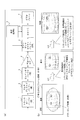
- FIG. 1 is a diagram for explaining a technical problem when a Side-by-Side video is distributed.
- a conventional 3D display device that supports the Side-by-Side method expands the left-eye image and the right-eye image to the size of the display device (display screen).
- the 2D display device displays the left-eye image and right-eye image side by side as a single image. To do. Therefore, as shown in the lower right part of FIG. 1, an image in which the left-eye image and the right-eye image are arranged in the horizontal direction is displayed as it is on the screen of the 2D display device. For this reason, the viewer sees two similar 2D images arranged side by side on the display screen. In this case, the viewer cannot enjoy the side-by-side video stream as a 2D image having the original display screen size.
- the 2D display device reproduces the image in which the image for the right eye and the image for the left eye are arranged in the horizontal direction as it is, an operator who broadcasts or distributes 3D video is required to A viewer who uses the display device receives a complaint that an image in which a left-eye image and a right-eye image are arranged in a horizontal direction is displayed instead of a 2D image.
- the conventional 3D display device assumes that the right-eye image is stored in the right half of the picture data and the left-eye image is stored in the left half of the image data. Then, the left-eye image and the right-eye image are cut out.
- 3D video cannot be displayed normally on the display screen.
- the video stream creator uses the TopAndBottom method for storing left-eye and right-eye images
- the layout of the images that make up the transmitted picture data is the same as the left-eye and right-eye images. Store side by side on top and bottom of one screen. In this case, the conventional 3D display device corresponding to the Side-by-Side method cannot correctly display 3D video.
- an object of the present invention is to provide an encoding method and a display that can correct the display contents in any of a conventional 2D display device, a new 2D display device, a conventional 2D display device, and a new 3D display device.
- An apparatus and a decoding method are provided.
- the encoding method uses a first screen area as a cropping area of picture data in which a left-eye image and a right-eye image are stored in each of the divided areas obtained by dividing the screen area.
- the display device or decoding method performs display processing by inputting a video stream, and the video stream includes a plurality of picture data and display information, and each of the picture data includes:
- Each of the divided areas obtained by dividing the screen area stores a left-eye image and a right-eye image
- the display information includes cropping information that specifies a cropping area to be used for display in the picture data.
- the cropping information in the 2D display information is a screen used for 2D display among the left-eye image and the right-eye image.
- the area is designated as the cropping area, and the primary frame buffer unit, the secondary frame buffer unit, the compressed picture data is decoded, and the uncompressed picture data is written to the primary frame buffer unit and stored in the primary frame buffer unit.
- the uncompressed picture data is subjected to display processing according to the display information, the processing result is written to the secondary frame buffer unit, and stored in the primary frame buffer unit according to the cropping information in the 2D display information
- the portion designated as the cropping area in the picture data being read is read out, scaled according to the scaling information in the 2D display information, and written in the secondary frame buffer unit.
- another display device or decoding method performs display processing by inputting a video stream, and the video stream includes a plurality of picture data and display information, and each of the picture data Stores a left-eye image and a right-eye image in each of the divided areas obtained by dividing the screen area, and the display information specifies a cropping area used for display in the picture data.
- the cropping information in the 2D display information is used for 2D display of the left-eye image and the right-eye image.
- the surface area is designated as the cropping area, the primary frame buffer unit, the secondary frame buffer unit, the compressed picture data is decoded, and the uncompressed picture data is written to the primary frame buffer unit.
- the stored uncompressed picture data is subjected to display processing according to the display information, the processing result is written to the secondary frame buffer, and the current display mode is selected from 2D playback mode and 3D playback mode. If the current display mode is the 3D playback mode, the 3D display information is prioritized over the 2D display information. Refer to the picture data stored in the primary frame buffer unit according to the cropping information in the 3D display information. Of the data, a portion designated as a cropping area is read out, scaled according to the scaling information in the 3D display information, and written in the secondary frame buffer unit.
- the encoding method according to the present invention can correctly display 2D video on a 2D display device and 3D video on a 3D display device. In that sense, a highly compatible 3D video stream can be provided.
- the 2D display information according to the embodiment of the present invention is new in that the setting of the cropping information in which either the right-eye image or the left-eye image is designated as the cropping region is different from the conventional 2D display information.
- a conventional 2D display information format can be used. Therefore, when a 3D video stream including 2D display information is supplied to a conventional 2D display device, the conventional 2D display device is cropped based on the cropping information or scaling information in the new 2D display information by existing hardware. Or scaling can be performed. By doing so, the correct contents can be displayed even when the 3D video stream is transmitted to the conventional 2D display device. Therefore, the compatibility of the created video stream can be improved. In addition, since the display contents are correct by using the hardware of the conventional 2D display device, the practical value is great.
- the display device can easily find the correct right-eye image region and left-eye image region based on the 3D display information.
- Each of the right-eye image and the left-eye image stored in the same picture data can be correctly cut out and used for stereoscopic playback. Accordingly, even if the right-eye image and the left-eye image are stored side by side in the horizontal or vertical direction in the picture data, or the ratio of the right-eye image and the left-eye image to the picture data is different.
- 3D display information By extracting 3D display information from the video stream, the right-eye image and the left-eye image stored in the picture data can be correctly cut out regardless of the transmission method, and stable stereoscopic reproduction can be realized.
- 3D video producers can freely set how to store or transmit right-eye and left-eye images, and the ratio of right-eye and left-eye images to picture data compared to conventional technologies. can do.
- the display process of how the L-R stored images in the side-by-side method and the top-and-bottom method are used for display is shown.
- a stereoscopic image recognized by the user by viewing the left-eye image and the right-eye image in the 3D section through the glasses is shown.
- the decoder model of MPEG-4 AVC video decoder is shown.
- a method of specifying a cropping area by cropping information is shown. It is a figure which shows the change of a frame concretely.
- the left-eye image is arranged on the left side, and four layout patterns in the side-by-side method are shown. It is a figure which shows two layout patterns in a top and bottom system.
- FIG. 6 is a flowchart illustrating a processing procedure of the encoding method according to the first embodiment.
- 12 is a flowchart illustrating another example of the processing procedure of the encoding method according to the first embodiment.
- 6 is a flowchart for explaining generation of an LR stored image and display information according to the first embodiment. It is a flowchart explaining the encoding process of a LR stored image.
- FIG. 6 is a flowchart for explaining a multiplexing process according to the first embodiment. It is a figure which shows the internal structure of a 2D display apparatus. 2 is a diagram showing an internal configuration of a 2D digital television 300. It is a figure which shows the internal structure of a 3D display apparatus. 1 is a diagram illustrating a 3D digital television 100.
- FIG. 10 is a flowchart illustrating a processing procedure of a decoding method according to the second embodiment. 10 is a flowchart illustrating in detail a 3D mode display process according to the second embodiment. It is a figure which shows designation
- 14 is a flowchart illustrating details of generation of an LR stored image and display information according to the third embodiment.
- 14 is a flowchart illustrating an LR stored image encoding procedure according to the third embodiment.
- 14 is a flowchart showing a procedure for encoding slice data constituting an LR stored image (i) according to the third embodiment.
- 14 is a flowchart illustrating a processing procedure of a decoding method according to the third embodiment.
- 10 is a flowchart illustrating a processing procedure of 3D mode display processing according to the third embodiment. It is a figure which shows designation
- a process of obtaining a full HD left-eye image and a right-eye image from a half-HD2 video stream and a half-HD2 extended stream is shown.
- the left-eye image (A) is used as the base video
- the right-eye image (B), the left-eye difference video (C), and the right-eye difference video (D) are compressed using an inter-view reference such as MPEG-4 AVC.
- An example of generating parallax images of a left-eye image and a right-eye image from a 2D video and a depth map is schematically shown. It is a figure explaining the example of application in the case of applying 2D display information and 3D display information to a depth map.
- the left-eye image and the right-eye image are stored as separate video streams in one transport stream. It is a figure which shows an example of the internal structure of the left-eye video stream for the stereoscopic vision by a multi view encoding system, and the right-eye video stream.
- the encoding method provided with the above problem solving means can be implemented by incorporating it as a processing procedure of a computer program in an authoring computer system.
- the display device provided with the above problem solving means can be implemented as an industrial product such as a digital television.
- the decoding method provided with the above problem solving means can be implemented in the digital television by being incorporated as a processing procedure of a computer program.
- the digital television which is a product of the display device includes a 3D digital television 100 capable of viewing 3D video and a 2D digital television 300 capable of reproducing only 2D video without supporting playback of 3D video. .
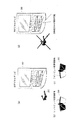
- Fig. 2 (a) is a diagram showing a usage pattern of the 3D digital television. As shown in FIG. 2A, the user views 3D video using the digital television 100 and 3D glasses 200.
- the 3D digital television 100 can display 2D video and 3D video, and displays video by playing back a stream included in the received broadcast wave.
- the 3D digital television 100 realizes stereoscopic vision by wearing 3D glasses 200 by the user.
- the 3D glasses 200 include a liquid crystal shutter, and allow a user to view a parallax image by the continuous separation method.
- the parallax image is a set of videos composed of a video that enters the right eye and a video that enters the left eye, and performs stereoscopic viewing so that only pictures corresponding to each eye enter the user's eyes.
- FIG. 2B shows a shutter configuration when viewing the left-eye image. At the moment when the image for the left eye is displayed on the screen, the 3D glasses 200 described above make the liquid crystal shutter corresponding to the left eye translucent and the liquid crystal shutter corresponding to the right eye light-shielded.
- FIG. 1 shows a shutter configuration when viewing the left-eye image.
- 2C shows a shutter configuration when viewing the right-eye image.
- the liquid crystal shutter corresponding to the right eye is made transparent and the liquid crystal shutter corresponding to the left eye is made light-shielding contrary to the previous case.
- the 2D digital television 300 cannot realize a stereoscopic view, as shown in FIG.
- the 2D digital television 300 can display only 2D video, and can reproduce the stream included in the received broadcast wave only as 2D video.
- Embodiment 1 As Embodiment 1, a specific form of an encoding method based on the presence of the display device will be described. This encoding method is to generate a video stream and a transport stream from the left-eye image and the right-eye image that are the original images, and the specific procedure largely depends on the structure of the video stream and the transport stream. . Prior to the description of the encoding method, the basic structure of the transport stream will be described.
- Digital stream of MPEG-2 transport stream (Transport Stream: TS) format is generally used for transmission on broadcast waves of digital television.
- the MPEG-2 transport stream is a standard for multiplexing and transmitting various streams such as video and audio. It is standardized in ISO / IEC13818-1 and ITU-T recommendation H222.0.
- FIG. 3 is a diagram showing the structure of a digital stream in the MPEG-2 transport stream format.
- a transport stream is obtained by multiplexing a video stream, an audio stream, a subtitle stream, and the like.
- the video stream stores the main video of the program
- the audio stream stores the main audio portion and sub-audio of the program
- the subtitle stream stores the subtitle information of the program.
- the video stream is encoded using a method such as MPEG-2 or MPEG-4 AVC.
- the audio stream is compressed and encoded by a method such as Dolby AC-3, MPEG-2 AAC, MPEG-4 AAC, HE-AAC.
- the picture data string 501 is converted into a PES packet string 502 and then converted into a TS packet string 503.
- the audio signal 504 is converted into an audio frame sequence through quantization and sampling.
- the audio frame is converted into a PES packet sequence 505 and then converted into a TS packet sequence 506.
- RCS Region Composition Segment
- PDS Pallet Define Segment
- ODS Object DefinementSegmentt
- the stream management information is information for managing a video stream, an audio stream, and a subtitle stream, which are stored in a system packet called PSI (Program Specific Information) Information and multiplexed in a transport stream, as one broadcast program.
- PSI Program Specific Information
- the stream management information includes types such as PAT (Program Association Table), PMT (Program Map Table), event information table EIT (Event Information Table), and service information table SIT (Service Information Table).
- PAT indicates what the PMT PID used in the transport stream is, and is registered in the PAT array of the PAT itself.
- the PMT has PID of each stream such as video / audio / subtitles included in the transport stream and stream attribute information corresponding to each PID, and has various descriptors related to the transport stream.
- the descriptor includes copy control information for instructing permission / non-permission of copying of the AV stream.
- SIT is information defined according to the standard of each broadcast wave using a user-definable area in the MPEG-2 TS standard.
- the EIT has information related to the program such as the program name, broadcast date and time, and broadcast content.
- FIG. 4 is a diagram for explaining the data structure of the PMT in detail.
- a “PMT header” describing the length of data included in the PMT is arranged.
- a plurality of “descriptors # 1 to #N” related to the transport stream are arranged.
- information such as the above-described copy control information is described as a descriptor.
- a plurality of “stream information # 1 to #N” regarding each stream included in the transport stream is arranged.
- the stream information is composed of a stream descriptor that describes a stream type for identifying a compression codec of the stream, a stream PID, and stream attribute information (frame rate, aspect ratio, etc.).
- the video stream generated by the encoding method of the first embodiment is compressed and encoded by a moving image compression encoding method such as MPEG-2, MPEG-4 AVC, SMPTE VC-1.
- a moving image compression encoding method such as MPEG-2, MPEG-4 AVC, SMPTE VC-1.
- the amount of data is compressed using redundancy in the spatial direction and temporal direction of moving images.
- inter-picture predictive coding is used as a method of using temporal redundancy.
- inter-picture predictive coding when a certain picture is coded, a picture that is forward or backward in display time order is used as a reference picture. Then, the amount of motion from the reference picture is detected, and the amount of data is compressed by removing the redundancy in the spatial direction for the difference value between the motion compensated picture and the picture to be encoded.
- the video stream of each encoding method as described above is common in that it has a GOP structure as shown in FIG.
- a video stream is composed of a plurality of GOPs (Group of Pictures), and editing and random access of moving images are possible by using GOP as a basic unit of encoding processing.
- a GOP is composed of one or more video access units.
- FIG. 5A is an example of a GOP.
- a GOP is composed of multiple types of picture data such as an I picture, a P picture, a B picture, and a Br picture.
- I picture is a unit of encoding that includes both a frame and a field.
- a picture that is inter-picture prediction encoded with reference to one already processed picture is called a P picture, and a picture that is inter-picture predictively encoded with reference to two already processed pictures at the same time is called a B picture.
- a picture that is referred to by other pictures in the B picture is called a Br picture.
- a frame in the case of a frame structure and a field in the case of a field structure are referred to herein as “video access units”.
- the video access unit is a unit that stores encoded data of a picture, and stores data of one frame in the case of a frame structure and one field in the case of a field structure.
- the top of the GOP is an I picture. If both MPEG-4 AVC and MPEG-2 are explained, the explanation will be redundant. In the following explanation, unless otherwise specified, it is assumed that the compression encoding format of the video stream is MPEG-4 AVC. Let's proceed with the explanation.
- FIG. 5B shows the internal configuration of the video access unit corresponding to the I picture data located at the head of the GOP.
- the video access unit at the head of the GOP is composed of a plurality of network abstraction layer (NAL) units.
- NAL network abstraction layer
- the video access unit at the head of the GOP is composed of NAL units such as an AU identification code, a sequence header, a picture header, supplementary data, compressed picture data, and padding data.
- AU identification code is a start code indicating the head of the video access unit.
- the “sequence header” stores common information in a playback sequence composed of a plurality of video access units. Common information includes resolution, frame rate, aspect ratio, bit rate, and the like.
- the “picture header” stores information such as the encoding method of the entire picture.
- “Supplementary data” is additional data that is not essential for decoding the compressed data, and stores, for example, closed caption character information and GOP structure information to be displayed on the TV in synchronization with the video.
- the “padding data” stores meaningless data for adjusting the format. For example, it is used as stuffing data for maintaining a predetermined bit rate.
- the contents of the AU identification code, sequence header, picture header, supplemental data, compressed picture data, and padding data differ depending on the video encoding method.
- the AU identification code is AU delimiter (Access Unit Delimiter)
- the sequence header is SPS (Sequence Parameter Set)
- the picture header is PPS (Picture Parameter Set).
- compressed picture data corresponds to a plurality of slices
- supplemental data corresponds to SEI (Supplemental Enhancement Information)
- padding data corresponds to FillerData.
- the sequence header corresponds to sequence_Header, sequence_extension, group_of_picture_header, the picture header corresponds to picture_header, picture_coding_extension, the compressed picture data corresponds to multiple slices, and the supplemental data corresponds to user_data.
- Each stream included in the transport stream is identified by a stream identification ID called PID. By extracting the PID packet, the decoder can extract the target stream. The correspondence between PID and stream is stored in the descriptor of the PMT packet described later.
- FIG. 6 is a diagram illustrating a process in which individual picture data is converted into a PES packet.
- PES Packetized Elementary Stream
- the first row in FIG. 6 shows a video frame sequence of the video stream.
- the second level shows a PES packet sequence.
- a plurality of Video Presentation Units I picture, B picture, and P picture in the video stream are divided for each picture and stored in the payload of the PES packet.
- Each PES bucket has a PES header, and the PES header stores the PTS (Presentation Time-Stamp) that is the display time of the picture and the DTS (Decoding Time-Stamp) that is the decoding time of the picture. .
- the PES packet obtained by converting individual picture data is divided into a plurality of parts, and each divided part is arranged in the payload of the TS packet.
- FIG. 7 shows a data structure of TS buckets constituting the transport stream.
- the TS packet is a 188-byte fixed-length packet composed of a 4-byte TS header, an adaptation field, and a TS payload.
- the TS header is composed of transpot-priority, PID, adaptation_field_control, and the like.
- the PID is an ID for identifying a stream multiplexed in the transport stream as described above.
- the transport_priority is information for identifying the type of packet in TS packets with the same PID.
- adaptation_field_control indicates whether an adaptation field and a TS payload exist.
- adaptation_field_control is "1" only TS payload exists
- adaptation_field_control is "2” only adaptation field exists
- adaptation_field_control is "3” both TS payload and adaptation field exist Indicates to do.
- the adaptation field is a storage area for information such as PCR and data to be stuffed to make the TS packet a fixed length of 188 bytes. PTS packets are divided and stored in the TS payload.
- each picture data is converted into a transport stream through the process of PES packetization and TS packetization, and each parameter constituting the picture data is converted to a NAL unit. I understand. This completes the description of the transport stream. Next, details of 2D display information and 3D display information will be described.
- Display information is information defining display control for a display device.
- the display device that has received the video stream or the transport stream can change the region of the encoded frame or the region actually used for display based on the display information extracted from the video stream.
- 2D display information and 3D display information are required to be stored in a form compatible with the video access unit structure in MPEG-4MAVC.
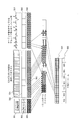
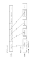
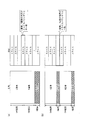
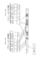
- FIG. 8 shows a specific example of the storage contents of how 2D display information and 3D display information are stored.
- an example in which side-by-side 3D video is stored using a full HD frame size is shown.
- the first level in the figure shows the NAL units that make up the video access unit of the MPEG-4 AVC video stream.
- the second level is the PES packet sequence
- the third level is the TS packet sequence
- the fourth level is The stream management information
- the fifth level is a transport stream, which is the same as that shown in FIG.
- the first level shows the NAL unit.
- This NAL unit constitutes picture data stored in the PES packet, and is the same as FIG. 5B.
- 2D display information is stored in the “sequence header” which is one of the NAL units.
- a frame w3 in the figure shows a close-up of the internal structure of the compressed slice data. As shown in this frame, the compressed slice data constitutes a multi-view stored image.
- a multi-view stored image refers to an image in which viewpoint images from a plurality of viewpoints are stored in a pixel area (referred to as a frame area) having a predetermined resolution formed by one picture data. Therefore, when picture data is decoded, stereoscopic playback can be performed by extracting viewpoint images corresponding to the respective viewpoints from the frame area.
- the parallax image is a stereo image and is composed of a combination of a left-eye image and a right-eye image, two viewpoint images, a left-eye image and a right-eye image, are stored in the picture data.
- the multi-view storage image in which the left-eye image and the right-eye image are stored is referred to as an “LR storage image”. Since it will be complicated to explain all the variations of the multi-view stored image, in the following description, the multi-view stored image is an LR stored image that stores a set of left-eye images and right-eye images as viewpoint images. The following explanation will be advanced.
- the compressed picture data for forming the video stream is such that the full HD left-eye image is down-converted to half HD and stored in the left region of the picture, and the full HD right-eye image is Down-converted to half HD and stored in the area on the right side of the picture. Accordingly, the left-eye image and the right-eye image are stored side by side in a full HD frame.
- rame w2 in the figure shows a close-up of the internal structure of the sequence header.
- 2D display information is stored in the sequence header.
- the 2D display information includes cropping information and scaling information.
- a broken line frame indicates a range specified by the cropping information.
- the frame w1 in the figure shows a close-up of the internal structure of supplementary data and stream management information.
- 3D display information is arranged in supplemental data and stream management information.
- the 3D display information is stored in the supplemental data.
- the 3D display information is not stored in the supplemental data, it is preliminarily stored in the stream management information.
- the 3D display information is specifically stored as one of the stream descriptors corresponding to the video stream.
- the stream descriptor including 3D display information is preferably stored in an undefined portion of the AVC video descriptor.
- the stream descriptor including 3D display information is preferably stored in an undefined part of the video encoding / decoding control descriptor.
- the 3D display information includes “cropping information” and “scaling information” similarly to the 2D display information.
- the cropping information of the 3D display information specifies the entire area of full HD picture data, unlike the 2D display information.
- the scaling information a value for displaying full HD data as it is in full HD is set. That is, the scaling ratio is equal.
- 3D display information is stored in the SEI message, and for MPEG-2, 3D display information is stored in user_data and extension_data.
- 3D display information can be stored in either supplementary data or stream management information.
- the advantages of using each of these as storage locations for 3D display information are described.
- the storage method of LR stored images can be changed on the video stream time axis. Therefore, it is optimal for changing the content of display control by 3D display information from moment to moment.
- the 3D display information may be stored only in the first GOP picture. In this case, since the playback device only needs to analyze each GOP, the 3D display information can be easily analyzed. become able to.
- the stream management information is information that is valid for one transport stream
- the control content by the 3D display information is fixed over the entire video stream time axis. Therefore, when it is desired to realize common display control for one or a plurality of programs, it is optimal to arrange 3D display information in the stream management information. This completes the description of the storage location of 3D display information. Next, details of the storage location of 3D system information will be described.
- Frame w4 in the figure closes up the internal structure of supplementary data.
- 3D system information is arranged in the supplemental data.
- the 3D system information indicates the type of 3D system.
- the 3D system includes a frame compatible system and a multi-view encoding system, and the frame compatible system includes a side-by-side system, a top-and-bottom system, and a line alternative system.
- the 3D system information stores information that can identify the type of the above-described system.
- an identifier “side-by-side method” is set in the 3D method information.
- 3D format information is included in supplementary data, 3D format information is stored in the SEI message for MPEG-4 AVC, and 3D format information is stored in user_data and extension_data for MPEG-2.
- frame_packing_arrangement SEI is used as 3D format information as supplementary data that defines the type of frame compatible 3D format.
- the frame compatible method is a method of performing normal moving image compression coding by thinning out or reducing the corresponding pictures of the left-eye video and right-eye video and combining them into one picture.
- One example is a side-by-side method. In the side-by-side method, the corresponding pictures of the left-eye video and right-eye video are respectively compressed in half in the horizontal direction and then combined in one picture by arranging them side by side.
- the moving picture by the synthesized picture is streamed by performing normal moving picture compression coding.
- the stream is decoded into a moving image based on a normal moving image compression encoding method.
- Each picture of the decoded moving image is divided into left and right images, and each picture is expanded twice in the horizontal direction, thereby obtaining a left eye image and a right eye image.
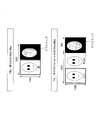
- FIG. 9 (a) shows a display process of how the L-R stored image in the side-by-side format is used for display.
- a picture belonging to the GOP structure is shown.
- the picture in the first row is a side-by-side LR stored image.
- This L-R stored image constitutes the second-stage 3D video section.
- the section is configured by displaying the left-eye image and the right-eye image stored in the LR stored image as one picture.
- Arrows ya1 and ya2 between the first level and the second level schematically show the process in which the left-eye image and right-eye image in the LR stored image are displayed by being cut out and enlarged. Show.
- Fig. 9 (b) shows the display process of how the LR stored image in the top and bottom method is used for display.
- a picture belonging to the GOP structure is shown.
- the picture in the first row is a top-and-bottom LR stored image.
- This L-R stored image constitutes the second-stage 3D video section.
- the 3D video section is configured by displaying the left-eye image and the right-eye image stored in the LR stored image as one picture.
- the arrows yb1 and yb2 between the first level and the second level schematically indicate the process of displaying each left-eye image and right-eye image in the LR stored image by being cut out and enlarged. Show.
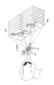
- FIG. 10 shows a stereoscopic image recognized by the user by viewing the left-eye image and the right-eye image in the 3D video section through the glasses.
- a user wearing stereo glasses is drawn on the left side, and on the right side is an example of the dinosaur skeleton that is the object viewed from the left eye, and when the dinosaur skeleton that is the object is viewed from the right eye Examples are shown respectively.
- stereo glasses when the light and left eye light and light are alternately switched, the scenes entering the left eye and the scene entering the right eye are superposed in the user's brain due to the afterimage reaction of the eyes.
- a stereoscopic image existing on the extension line in the center of the image can be viewed. This completes the description of 3D playback using a video stream.
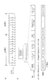
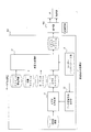
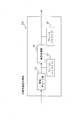
- FIG. 11A shows a decoder model of an MPEG-4 AVC video decoder.
- the decoder model in this figure is comprised of TB1, MB2, EB3, decoder core 4, DPB5, scaler 6, video plane 7, and display processing unit 8.
- Transport Buffer (TB) 1 is a buffer for temporarily storing the TS packets as they are when TS packets including a video stream are output from the demultiplexing unit.
- Multiplexed Buffer (MB) 2 is a buffer for temporarily storing PES packets when outputting a video stream from TB to EB.
- MB Multiplexed Buffer
- Elementaly Buffer (EB) 3 is a buffer in which the video access unit in the encoded state is stored. The PES header is removed when data is transferred from MB to EB.
- the decoder core 4 creates a frame / field image by decoding each video access unit of the video elementary stream at a predetermined decoding time (DTS).
- DTS decoding time
- the decoder core 4 performs motion compensation using picture data existing in the future direction or the past direction as a reference picture.
- Decoded Picture Buffer (DPB) 5 is a buffer that temporarily stores decoded frame / field images.
- the video decoder 57 decodes a video access unit such as a P picture or a B picture subjected to inter-picture prediction encoding, it is used to refer to the already decoded picture.
- the scaler 6 performs scaling conversion on the picture data stored in the decoded picture buffer, and writes the converted picture data to the video plane.
- the video plane 7 stores the pixel data for one screen constituting the converted picture data for display.
- the display processing unit 8 executes cropping control according to the cropping information and scaling control according to the scaling information.
- the above is an explanation of an example of the decoder model of the video decoder.
- the embodiment of the display device according to the present invention is not limited to the decoder model of the MPEG-4 AVC video decoder described above.
- FIG. 11B shows the stored contents of the decoded picture buffer, and the right side shows the stored contents of the video plane.
- the cropping information designates an area to be actually displayed from the frame area as a “cropping area”.
- the “frame area” is a set of pixels obtained by decoding a video access unit corresponding to one frame.
- the full HD picture data is The composed 1920 ⁇ 1080 pixels constitute this frame region.
- the decoder decodes the video access unit that has been made into NAL units, the frame area is constructed in a decoded picture buffer.
- the “cropping area” refers to a range specified by the cropping information in the frame area.
- the cropping area designated by the cropping information is shown.
- an area to be actually displayed is designated as a “cropping area” from the frame area which is the content stored in the decoded picture buffer. Therefore, when the display information is supplied to the decoder, the display processing unit performs a process of cutting out the cropping area from the contents stored in the decoded picture buffer according to the cropping information of the 2D display information and transferring it to the video plane. Will do.
- An arrow yc1 schematically shows the cropping process.
- the scaling information is information for scaling the cropping area to a size suitable for display on a display such as a television.
- the middle of FIG. 10B shows the cropping area specified by the cropping information.
- the scaling information is used to specify the magnification at which the cropping area cut out from the decoded picture buffer is displayed. Therefore, when the display information is supplied to the decoder, the scaler performs resolution conversion according to the scaling information of the display information, and writes the converted cropping area on the video plane.
- a white arrow yc2 in the figure schematically shows the process of resolution conversion.
- FIG. 12 shows how to specify the cropping area based on the cropping information.
- display coordinates in the XY coordinate system are set for the image.
- the upper left of the drawing is the origin (0, 0)
- the right direction is the positive direction of the X axis
- the lower direction is the positive direction of the Y axis.
- the same notation as in this figure is used for the notation of the XY coordinate system.
- FIG. 12A the difference between the upper line / underline / left line / right line of the cropping area and the upper line / underline / left line / right line of the encoded frame area is designated as the crop amount in the vertical and horizontal directions.
- the designation method is shown.
- FIG. 12B defines the cropping area by defining the top left coordinates of the cropping area with the top left coordinates of the frame area in the decoded picture buffer as the origin, and defining the horizontal and vertical widths of the cropping area. The designation method is shown.
- the characteristic feature of this embodiment is that, as described above, these cropping information and scaling information exist in each of 2D display information and 3D display information.
- the cropping information in the 2D display information defines information necessary for cropping when the display device displays 2D video using the video stream.
- the cropping information of 2D display information specifies the occupied area of 2D compatible images in the frame area.
- a “2D compatible image” is a viewpoint image used for display in both the 3D mode and the 2D mode.
- a parallax image for stereoscopic reproduction is composed of a plurality of viewpoint images. Of these multiple viewpoint images, an image suitable for display in the 2D mode is designated by the cropping information of the 2D display information.
- the parallax image is a stereo image and consists of a combination of a left-eye image and a right-eye image, out of the two viewpoint images, the left-eye image and the right-eye image, the one suitable for display in 2D mode is 2D. It is specified by the cropping information of the display information.
- the parallax image is a multi-channel image and is composed of three or more viewpoint images such as a left-eye image, a right-eye image, a center, an upper right image, a lower right image, an upper left image, and a lower left image Of these viewpoint images, those suitable for playback in the 2D mode are designated by the cropping information of the 2D display information.
- the description becomes complicated. Therefore, in the following description, the description will be made assuming that the 2D compatible image is the image for the left eye.
- the cropping information and scaling information in the 2D display information specify a part to be cropped when the display device displays 2D video using the video stream, and information necessary for scaling the cropped image. .
- the cropping information in the 3D display information indicates the occupied area occupied by the combined image of the 2D compatible image and the 2D incompatible image in the frame area as the cropping area.
- 2D incompatible image refers to a video that is not displayed in 2D playback mode but is displayed only in 3D mode. Since the parallax images constituting the stereoscopic video are composed of two or more viewpoint images, one of these viewpoint images is a 2D compatible image, and the remaining viewpoint images are 2D incompatible images. In the present embodiment, since it is a premise that a plurality of viewpoint images are stored in one picture data, the entire occupied area occupied by the plurality of viewpoint images out of the entire area of the frame area is 3D. It is specified by the cropping information of the display information.
- the area specified by the cropping information of the 2D display information is selected from the cropping area specified by the cropping information of the 3D display information. If removed, 2D incompatible images can be obtained.
- the display device performs a process of cutting out the cropping area specified by the cropping information of the 2D display information, and obtains a left-eye image that is a 2D compatible image. The left-eye image thus obtained is written to the left-eye video plane.
- the display device performs a process of removing the cropping area specified by the cropping information of the 2D display information from the cropping area specified by the cropping information of the 3D display information.
- a right-eye image that is a compatible image is obtained.
- the right-eye image thus obtained is written into a stereoscopic video plane. By doing so, the left-eye image and the right-eye image are provided for display.
- the cropping information of the 3D display information defines information necessary for the cropping when the display device displays 3D video using the video stream.
- the scaling information in the 3D display information is determined by the display device. Specifies the information required to scale the cropped image when displaying 3D video using a video stream.
- Supplied data which is one of the NAL units of the video access unit, or stream management information such as a PMT bucket may or may not include “3D display information” and “3D system information”.
- a flag Presence / absence flag
- the 3D digital television 100 uses the presence / absence flag of the PMT packet to decode “3D display information” and “3D system information” in the video stream before decoding. Can be prepared in advance, such as securing memory for analysis.
- the cropping information and the scaling information are fields or parameters that can determine the proportion of the image cropping area and scaling, a field or parameter having an equivalent function can be found from the syntax of the existing encoding method.
- the field or parameter that can determine the cropping area of the image for example, the following parameters in the MPEG-2 ISO / IEC 13818-2 standard are applicable.
- the parameter “frame_cropping_flag” described above is set to 1, and the above parameter “frame_crop_top_offset / frame_crop_bottom_offset / frame_crop_left_offset / frame_crop_left_offset” is set to the upper / lower / left / right Specify the crop amount.
- the vertical and horizontal sizes of the cropping area (display_horizontal_size, display_vertical_size of sequence_display_extension) and the difference information (frame_centre_horizontal_offset, frame_centre_vertical_offset of picture_display_extension) between the center of the encoded frame area and the center of the cropping area are used.
- a cropping area can be specified.
- the scaling information is information for scaling the cropping area to a size suitable for display on a display such as a television, it is sufficient if, for example, the aspect ratio at the time of display can be defined. This is because the reproduction apparatus can display the image by up-converting the cropping area as long as the aspect ratio can be obtained.
- aspect ratio information (asepct_ratio_idc) is stored in the SPS as scaling information.
- an aspect ratio of 4: 3 is specified to display a 1440 ⁇ 1080 cropping area enlarged to 1920 ⁇ 1080.
- aspect ratio information (aspect_ratio_information) is stored in the sequence-header.
- the left eye or right eye half area (half HD) is designated as the cropping area.
- the cropping area information is such that the upper, left, and lower crop amounts are 0 and the right crop amount is 960 pixels.
- the scaling information includes a value for changing from a half HD of 960 ⁇ 1080 to a full HD of 1920 ⁇ 1080. For example, in the case of MPEG-4AVC, a value of 16 (2: 1) is specified in aspect_ratio_idc.
- This 2D display information is information that an existing 2D display device refers to when performing 2D playback using the received side-by-side 3D video stream. Therefore, even if the 2D display device receives the video stream of the LR stored image (for example, side-by-side format), the 2D video is normally reproduced by cropping a part of the image and using it for actual reproduction. be able to.
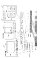
- FIG. 13 is a diagram specifically showing the change of the frame.
- a 2D digital television will be described as an example of a display device that displays 2D video
- a 3D digital television will be described as an example of a display device that displays 3D video.
- FIG. 13A shows an example of a decoding method of the side-by-side full HD example.
- FIG. 13 (a) shows a picture display process based on 2D display information.
- the left side of FIG. 13A shows the L-R stored image
- the middle shows the stored contents of the decoded picture buffer
- the right shows the stored contents of the video plane.
- the display processing unit 8 adds 2D display information to the decoded picture data. To determine the display method. Then, the display processing unit determines the cropping area according to the 2D display information.
- the left HD half HD area (an example of the first screen area) is specified in the 2D display information.
- the display processing unit stores the decoded picture buffer. From the obtained uncompressed picture data, the half HD area of the left screen is cut out and read out. The scaler scales clipped picture data according to the scaling information of the 2D display information and writes it to the video plane.
- the scaling information for 2D display information specifies the magnification (scaling factor) for up-converting half HD to full HD. Up-convert to full HD and display 2D video according to the display device.
- FIG. 13B shows a picture display process based on 3D display information.
- the left side of FIG. 13B shows the L-R stored image
- the middle shows the stored contents of the decoded picture buffer
- the right shows the stored contents of the video plane.
- the display processing unit determines a display method for the decoded picture data using 3D display information. If an uncompressed LR stored image is obtained in the decoded picture buffer, the cropping area in the decoded picture buffer is determined in accordance with the cropping information of the 3D display information.
- the full HD area an example of the second screen area
- the 3D digital television cuts out the full HD area as it is. Serve to the scaler.
- the 3D digital TV determines the scaling method according to the 3D display information.
- the scaling information of the 3D display information stores a value for displaying full HD as it is
- the scaler uses the full HD video as it is and writes it to the video plane.
- 3D digital television displays existing 3D video according to 3D format information.
- the side-by-side video is described in the 3D system information, so the side-by-side image for the left eye and the image for the right eye are up-converted, respectively, and the 3D system is adapted to the 3D system of the television. Display.
- a playback device that can decode only 2D video using a frame-compatible 3D video such as an LR stored image by configuring a video stream or a transport stream in the format as described above can be used.
- One of the images can be played back as 2D video at the TV display size, and can be played back as 3D video on a playback device that can play back as 3D video.
- a side-by-side full HD video stream a side-by-side left-eye or right-eye video is up-converted to full HD for playback on a playback device that can only play back 2D video.
- the side-by-side left-eye and right-eye video is up-converted to full HD and played back as 3D video. This completes the description of 2D display information and 3D display information.
- the layout pattern of the LR stored image that can cover 2D display information and 3D display information will be described.
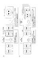
- FIG. 14 is a diagram showing four layout patterns in the side-by-side method.
- FIG. 14 (a) shows a layout pattern in which 2K ⁇ 1K full HD, that is, the resolution of the L-R stored image is 1920 ⁇ 1080, the left-eye image is arranged on the left side, and the right-eye image is arranged on the right side.
- a broken line frame in the figure schematically represents an area to be displayed as 2D video.
- the 2D display information for this layout pattern is intended to display a portion surrounded by a broken line frame, that is, a 960 ⁇ 1080 pixel left-eye image as 2D video.
- FIG. 14B shows a layout pattern in which the resolution of the 4K ⁇ 1K, that is, the L-R stored image is 3840 ⁇ 1080, the left-eye image is arranged on the left side, and the right-eye image is arranged on the right side.
- a broken line frame in the figure schematically represents an area to be displayed as 2D video.
- the 2D display information for this layout pattern is intended to display a portion surrounded by a broken line frame, that is, a 1920 ⁇ 1080 pixel full HD left-eye image as 2D video.
- FIG. 14C shows a layout pattern in which 3K ⁇ 1K, that is, the resolution of the L-R stored image is 2880 ⁇ 1080, the left-eye image is arranged on the left side, and the right-eye image is arranged on the right side.
- a broken line frame in the figure schematically represents an area to be displayed as 2D video.
- the 2D display information for this layout pattern is intended to display a portion surrounded by a broken line frame, that is, a 1920 ⁇ 1080 pixel full HD left-eye image as 2D video.
- FIG. 14D shows a layout pattern in which the resolution of the 4K ⁇ 2K, that is, the L-R stored image is 3840 ⁇ 2160, the left eye image is arranged on the left side, and the right eye image is arranged on the right side.
- a broken line frame in the figure schematically represents an area to be displayed as 2D video.
- the 2D display information for this layout pattern is intended to display a portion surrounded by a broken line frame, that is, a 1920 ⁇ 2160 pixel full HD left-eye image as 2D video.
- the 2D digital TV 300 uses the 2D display information to play the 2D video in full HD
- the 3D digital TV 100 uses the 3D display information. Can be played in full HD ⁇ 2.
- 2D digital TV 300 uses 2D display information to play back 2D video in full HD
- 3D digital TV 100 uses 3D video to display full 3D video. Can be played in HD x 2 screens.
- the above is an explanation of side-by-side. Next, details of the top and bottom will be described.
- FIG. 15 is a diagram showing two layout patterns in the top-and-bottom method.
- FIG. 15A is a 2K ⁇ 2K top-and-bottom LR storage image having a resolution of 1920 ⁇ 2160, the left-eye image is the upper side—the right-eye image is the lower side, and the upper half 1920 ⁇ 1080 left-eye images are displayed as 2D video. Since the left-eye image is displayed as the 2D video, the cropping information is set so that the 1920 ⁇ 1080 left-eye image having (0,0) as the upper left coordinate is displayed as the 2D video.
- FIG. 15B is a 2K ⁇ 1.5K top-and-bottom LR storage image having a resolution of 1920 ⁇ 1620, the left-eye image is the upper side—the right-eye image is the lower side, and the upper half 1920
- the image for the left eye of ⁇ 1080 is displayed as 2D video. Since the left-eye image is displayed as the 2D video, the cropping information is set so that the 1920 ⁇ 1080 left-eye image having (0, 0) as the upper left coordinate is displayed as the 2D video.
- 2K x 1.5K top-and-bottom 3D video 2D digital TV 300 plays 2D video in full HD using 2D display information, and 3D digital TV 100 uses 3D video to display 3D video using 3D display information.
- 3D display is possible with full HD (L) and half HD (R) up-converted after extracting the area. You can also convert full HD (L) to half-HD resolution and then upconvert again to display in 3D.
- 3D digital Playback on the television 100 can be performed appropriately.
- 3D video can be displayed in 3D by using a 3D display information to extract a 3D display area and then up-converting full HD (L) and half HD (R). This completes the description of the side-by-side and top-and-bottom layouts.
- L full HD
- R half HD
- the left-eye image and right-eye image displayed as 1920x1080 are placed in the upper half and lower half of the picture.
- the left-eye image and the right-eye image are 1920 ⁇ 540 and 1920 ⁇ 540, respectively.
- the slice data is composed of a plurality of macroblocks (a group of pixels such as 16 ⁇ 16).
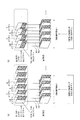
- FIG. 16A is a diagram illustrating a relationship between top-and-bottom picture data with a margin area added and slice data.
- the left side shows the image for the left eye, the image for the right eye, and the margin area constituting the top and bottom picture data.
- a 1920 ⁇ 8 blank area is arranged under the top-and-bottom right-eye image.
- 1920 ⁇ 540 is designated as the left-eye image in the 3D display information
- 1920 ⁇ 540 is designated as the right-eye image in the 3D display information.
- 1920 ⁇ 8 is designated as the blank area.
- the area defined by the crobbing information of the 2D display information indicates the upper or lower half area.
- the cropping area of 2D display information is set to the upper half, the upper, left, and right crop amounts are set to 0, and the lower crop amount is set to 540 pixels.
- the scaling information a value at the time of up-conversion from the upper or lower half area (1920 ⁇ 540) to full HD (1920 ⁇ 1080) is set.
- the right side shows a plurality of compressed slice data that are components of the video access unit. As shown in this figure, it can be seen that the pixel data of the left-eye image, right-eye image, and blank area constituting the top-and-bottom method is converted into slice data by 16 pixels.
- 1920 ⁇ 12 pixels located at the end of the left-eye image Since there is no correlation between these 1920 ⁇ 12 pixels located at the end of the left-eye image and 1920 ⁇ 4 pixels located at the tip of the right-eye image, 1920 ⁇ 12 pixels located at the end of the left-eye image If 1920 ⁇ 4 pixels located at the tip of the right-eye image are stored in one slice data, the compression efficiency is lowered.
- a 1920 ⁇ 540 rectangular area having (0,0) as the upper left coordinate is designated as a cropping area (an example of a first screen area) used for the left-eye image in the 3D display information.
- a 1920 ⁇ 540 rectangular area having (0,544) as the upper left coordinates is designated as a cropping area (an example of the second screen area) used for the right-eye image in the 3D display information.
- the playback content on 2D television and the playback content on 3D television can be made appropriate from the cropping information and scaling information.
- the offset from each side of the cropping area, the upper left coordinate, the horizontal width, and the vertical width are used.
- a type identifier can be used for the notation. This type identifier specifies the type of the standardized 2D display area.
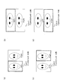
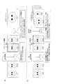
- FIG. 17 shows four types (types 1 to 4) of the region for 2D display assumed by the type identifier.
- Fig. 17 (a) shows the type 1 L-R stored image format and cropping area designation.
- TYPE 1
- the L-R stored image is a side-by-side method
- the left-eye image on the left side is designated as a cropping area (an example of a first screen area) of 2D display information.
- a broken-line frame in the figure schematically shows area designation by a cropping area of 2D display information.
- Fig. 17 (b) shows the type 3 LR stored image format and cropping area designation.
- TYPE 3
- the L-R stored image is a top-and-bottom method
- the upper left-eye image is designated as a cropping area (an example of a first screen area) of 2D display information.
- a broken-line frame in the figure schematically shows area designation by a cropping area of 2D display information.
- Fig. 17 (c) shows the type 2 LR stored image format and cropping area designation.
- TYPE 2
- the L-R stored image is a side-by-side format
- the right-eye image on the right side is designated as a cropping area (an example of a second screen area) of 2D display information.
- a broken-line frame in the figure schematically shows area designation by a cropping area of 2D display information.
- Fig. 17 (d) shows the type 4 L-R stored image format and cropping area designation.
- TYPE 4
- the L-R stored image is a top-and-bottom system
- the lower right-eye image is designated as a cropping area (an example of a second screen area) of 2D display information.
- a broken-line frame in the figure schematically shows area designation by a cropping area of 2D display information.
- “2D video display information” indicates “right side of Side-by-Side”.
- the right side of the Side-by-Side method may be used when performing 2D playback, and the “left side” may be further combined when displaying 3D video.
- 3D system information indicating whether the video is 2D video, Side-by-Side or TopandBottom
- the hardware resource premised on the above encoding method is a hardware resource of an authoring computer system used for creating a digital broadcast program in a broadcasting station.
- the authoring computer system includes a network drive, a server computer, and a client computer, and each computer includes an MPU, ROM, and RAM. These entire authoring computer systems are called "data creation devices".
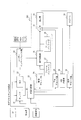
- FIG. 18 shows the internal configuration of a broadcasting station that broadcasts a transport stream.
- the broadcasting station includes a data creation device 401 that is an authoring computer system and a transmission unit 402.
- the data creation device 401 includes a video encoding unit 11, a multiplexing processing unit 12, a data storage method determination unit 13, and a user interface 14.
- the drum symbol in the figure represents “hard disk storage”.
- the data creation device stores the storage that stores the 3D video original image, the storage that stores the video stream, the storage that stores the audio stream, the storage that stores the subtitle stream, and the stream management information. Storage and storage for storing transport streams.
- These storages are network drives in the local network, and 3D video originals, video streams, audio streams, etc. are stored as files in a predetermined directory structure of these storages.
- the video encoding unit 11 and the multiplexing processing unit 12 are server computers in the local network, and access the storage as described above through the local network, and read various streams and write transport streams.
- each of the video encoding unit 11 and the multiplexing processing unit 12 will be described.
- the video encoding unit 11 reads the 3D video original image stored in the storage, performs compression encoding, and writes the video stream obtained by the compression encoding to the storage.
- the 3D video original image stored in the storage includes an image image such as an uncompressed bitmap of the left-eye image and an image image such as an uncompressed bitmap of the right-eye image.
- the video encoding unit 11 performs encoding according to the designation of the data storage method determination unit 13 in accordance with a compression method such as MPEG-4 AVC or MPEG-2.
- a compression method such as MPEG-4 AVC or MPEG-2.
- the video encoding unit 11 After down-converting and storing each image side by side in a side-by-side manner in one frame, compression encoding is performed.
- the video encoding unit 11 stores the 2D display information in the sequence header in the compression encoded stream, stores the 3D display information in the supplemental data, and then the compressed video stream is stored in the storage as a video stream. Write.
- the video encoding unit 11 converts the LR stored image into a video access unit by adding a sequence header and supplementary data to the encoded slice that forms the LR stored image corresponding to the head of the video sequence.
- the supplementary data is added to the coded slices constituting the LR stored image other than the head of the video sequence, thereby converting the LR stored image into a video access unit.
- 2D display information including “cropping information” and “scaling information” is stored.
- the video encoding unit 11 further stores 3D display information including “cropping information” and “scaling information” in the supplementary data of the video stream.
- the video encoding unit 11 stores “3D system information” in the supplementary data.
- the multiplexing processing unit 12 multiplexes the generated video stream and other streams such as audio streams and subtitle streams, stores 3D display information in the stream management information of the video stream, and then stores the LR stored image.
- a video stream as picture data and stream management information about the video stream are converted into a transport packet sequence and multiplexed into an audio stream and a caption stream.
- the transport stream obtained by multiplexing is written to the storage.
- the transport stream written in the storage is provided to the transmission unit 402 and broadcast.
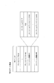
- the data storage method determination unit 13 and the user interface unit 14 are client computers. In each storage on the local area network, files storing 3D video originals, video streams, audio streams, subtitle streams, transport streams, etc. are visually represented by icons, thumbnails, etc. in the GUI. The user performs drag operations, drop operations, and click operations on the icons and thumbnails displayed on the GUI of the user interface 14 to perform operations on 3D video original images, video streams, audio streams, subtitle streams, transport streams, and the like.
- the data storage method determination unit 13 will be described below.
- the data storage method determination unit 13 presents a list of storage methods for the left-eye image and the right-eye image in the LR storage image through the user interface, and selects one of the storage methods listed in this list according to the operation from the user. specify. For example, the data storage method determination unit 13 designates “full HD side-by-side 3D video” when creating a transport stream of the video format shown in the example of FIG. This information is notified to the video encoding unit 11 and the multiplexing processing unit 12. Since there are various resolutions of the original images stored in the storage, the combination of the original image as the left-eye image and the original image as the right-eye image has the four side-by-side layouts shown in FIG. This corresponds to any of the two top-and-bottom layouts shown in FIG.
- the layout of the LR stored image is uniquely determined by the storage method of the image for the left eye and the image for the right eye, and the resolution of the image for the left eye and the image for the right eye.
- the scenario memory 13 automatically sets the cropping information designation and scaling information in the 2D display information from the determined layout.
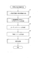
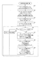
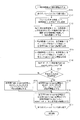
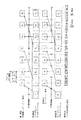
- FIG. 19 is a flowchart showing the processing procedure of the encoding method according to the present invention.
- the video encoding unit 11 generates the display information described above (step S1). Specifically, for each of the divided areas obtained by dividing the screen area constituting the picture data, the first eye image and the right eye image are stored (referred to as an LR stored image). First display information including cropping information designating a screen area as a cropping area and second display information including cropping information designating a second screen area as a cropping area are generated.
- the designation method determination method
- the video encoding unit 11 puts the generated display information in a predetermined position of the encoded image data, and generates a video stream in the format as described above (step). S2). According to the above encoding method, it is possible to provide a highly compatible 3D video stream capable of correctly displaying 2D video on a 2D display device and 3D video on a 3D display device.
- the basic processing procedure for creating a digital broadcast program is a process of generating an elementary stream other than a video stream, and a process of multiplexing a plurality of types of elementary streams thus generated. It is.
- Elementary streams other than video streams are audio streams and subtitle streams. In the multiplexing process, these video streams, audio streams, and subtitle streams are multiplexed.
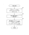
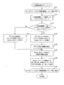
- FIG. 20 is a flowchart showing the processing procedure of the encoding method based on the premise of creating a digital broadcast program.
- a basic processing procedure step S3, step S4, step S5 for creating a digital broadcast program is added to the processing procedure common to the flowchart of FIG. 19 (step S1, step S2). It has become.
- the video encoding unit 11 follows the data storage method determined by the data storage method determination unit 13 from the input original image of 3D video and the above-described LR stored image. Display information is generated (step S1).
- the video encoding unit 11 puts the generated display information in a predetermined position of the encoded image data, and generates a video stream in the format as described above. (Step S2).
- step S3 an audio stream is generated (step S3) and a subtitle stream is generated (step S4), and the generated video stream, audio stream, and subtitle stream are multiplexed and multiplexed into one transport stream. (Step S5). If there is no audio stream or subtitle stream, step S3, step S4, and step S5 may be omitted.
- FIG. 20 corresponds to the main routine, and there are subroutine flowcharts in FIGS. 21 to 23 as subordinate flowcharts of this flowchart.
- FIGS. 21 to 23 will be described.
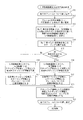
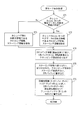
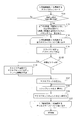
- FIG. 21 is a flowchart for explaining generation of the LR stored image and display information according to the first embodiment.
- the variable (i) in this flowchart is a control variable for specifying individual LR stored images to be processed. Therefore, in the subsequent flowcharts, the LR stored image that is the processing target in the i-th process of the loop is referred to as an LR stored image (i). Furthermore, the left-eye image and the right-eye image stored in the LR stored image (i) are represented as “left-eye image (i) and right-eye image (i)”, and a video access unit corresponding to the LR stored image (i) Is represented as “video access unit (i)”, and a frame corresponding to this video access unit is represented as “frame i”.
- the flowchart of this figure has a loop structure in which the processing of steps S12 to S20 is repeated for all frames (steps S10 and S11).
- the video encoding unit 11 sets the left-eye image (i) and the right-eye image (i) of the frame i obtained from the 3D video original image to half HD (step S12).
- the video encoding unit 11 converts the half-HD left-eye image (i) and right-eye image (i) into divided regions within the same screen.
- the LR stored image (i) is obtained by storing (step S13). Examples of the data storage method include the side-by-side method and the top-and-bottom method described above.
- step S14 For the generated LR stored image (i), scaling information that instructs the display device to convert from half HD to full HD is generated (step S14).
- the video encoding unit 11 determines whether or not the video for 2D playback is a left-eye image (step S15). If the determination result is “YES”, the left-eye of the LR stored image (i) is determined. The left-eye cropping information that specifies the image (i) as the cropping region is generated (step S18). The generated left-eye cropping information and the scaling information generated in step S14 are set as 2D display information for the frame i (step S19).
- right eye cropping information is generated for designating the right eye image (i) as the cropping area in the LR stored image (i) (step S16).
- the generated right-eye cropping information and the scaling information generated in step S14 are set as 2D display information for the frame i (step S17).
- cropping information specifying the entire screen as the cropping area and scaling information specifying 1 ⁇ are generated, and the generated cropping information and scaling information are used as 3D display information (step S20).
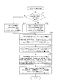
- step S14 may be omitted in the flowchart of FIG.
- the display device performs scaling based on the size of the display device (display screen). That is, cropping information is essential as information constituting 2D display information and 3D display information, but scaling information is an optional element that can be omitted.
- FIG. 22 is a flowchart for describing the encoding process of the LR stored image. In FIG. 22, it has a loop structure in which the processing from step S23 to step S28 is performed on the LR stored image for each frame (step S21, step S22).
- Step S23 a slice constituting the LR stored image (i) is encoded (step S23), and then it is determined whether the LR stored image (i) currently being encoded is a video access unit at the head of the video sequence. (Step S24) When the determination result is “YES”, the process proceeds to Step S25, where the sequence header, the picture header, and the supplemental data are added before the encoded slice to obtain the video access unit (i), and then The generated 2D display information is set in the sequence header of the obtained video access unit (i) (step S26).
- step S27 the picture header and supplemental data are added before the encoded slice to obtain the video access unit (i).
- step S28 the generated 3D display information is set in the supplementary data of the video access unit (i), thereby completing the encoding for the LR stored image (i) of the frame i. Subsequently, the above-described encoding process is repeated for all the frames to generate a video stream that can be used for reproduction.
- FIG. 23 is a flowchart for explaining multiplexing processing according to the first embodiment.
- the multiplexing processing unit 12 packetizes the transport stream for each elementary stream including the video stream (step S41), and uses the 3D display information obtained from the video encoding unit 11. Then, the 3D display information is stored in the stream management information (eg, PMT packet), and a transport packet including the PMT storing the 3D display information is generated (step S42). Next, the multiplexing processing unit 12 obtains a transport stream from the TS packet storing the PMT and the TS packet storing the elementary stream (step S43).
- the multiplexing processing unit 12 obtains a transport stream from the TS packet storing the PMT and the TS packet storing the elementary stream (step S43).
- the 2D display information is different from the conventional display information only in the setting of the cropping information in which either the right-eye image or the left-eye image is specified as the cropping area.
- the display information is the same as conventional display information that instructs the display device to perform cropping or scaling conversion. Therefore, when a 3D video stream including 2D display information is supplied to a conventional display device, the display device can perform cropping or scaling based on the cropping information and scaling information. By doing so, the display contents are correct by using the hardware of the conventional 2D display device, so that the practical value is great.
- the display device can easily find the right image area for the right eye and the image area for the left eye based on the 3D display information, and is stored in the same picture data.
- Each of the right-eye image and the left-eye image can be correctly cut out and used for stereoscopic playback. Accordingly, even if the right-eye image and the left-eye image are stored side by side in the horizontal or vertical direction in the picture data, or the ratio of the right-eye image and the left-eye image to the picture data is different.
- 3D display information By extracting 3D display information from the video stream, the right-eye image and the left-eye image stored in the picture data can be correctly cut out regardless of the transmission method, and stable stereoscopic reproduction can be realized.
- 3D video producers can freely set how to store or transmit right-eye and left-eye images, and the ratio of right-eye and left-eye images to picture data compared to conventional technologies. can do.
- the present embodiment relates to a display device that displays a transport stream generated in the above encoding process.
- FIG. 24 is a diagram illustrating an internal configuration of the 2D display device 310 according to the second embodiment.
- the 2D display device performs display processing on the input video stream, and includes a video decoding unit 24 (decoding unit), a display processing unit 25, a frame buffer (1) 27 (first frame buffer unit), The frame buffer (2) 28 (second frame buffer unit) is configured.
- the video decoding unit 24 When receiving the video stream, the video decoding unit 24 decodes the received stream.
- a frame of 3D video that is an L-R stored image is a frame configured in a side-by-side format.
- the video decoding unit 24 writes the decoded frame to the frame buffer (1) 27 and stores it.
- the display processing unit 25 extracts 2D display information from the decoded picture data stored in the frame buffer (1) 27, and determines a display method based on the cropping information and scaling information of the 2D display information. That is, display processing is performed on uncompressed picture data stored in the frame buffer (1) 27 according to the 2D display information, and the processing result is written in the frame buffer (2).
- the display processing unit 25 extracts 2D display information from the sequence header of the decoded video stream stored in the frame buffer (1) 27. In accordance with the cropping information in the extracted 2D display information, the part designated as the cropping area of the picture data stored in the frame buffer (1) 27 is read out to complete the cropping. Further, the display processing unit 25 performs scaling conversion on the read cropping area portion in accordance with the scaling information in the 2D display information, and then writes it in the frame buffer (2) 28.
- the frame buffer (1) 27 in FIG. 24 corresponds to the decoded picture buffer (DPB) 5 in FIG.
- the frame buffer (2) 28 in FIG. 24 corresponds to the video plane 7 in FIG.
- the embodiment of the 2D display device according to the present invention is not limited to the configuration of FIG. 11.
- a right-eye 2D image can be displayed without displaying an image in which a right-eye image and a left-eye image are arranged. Can do.
- the 2D digital television is a device such as a plasma television or a liquid crystal television capable of displaying 2D video, and receives a transport stream for sending a video stream.
- the internal configuration of the 2D digital television has a configuration in which components for ensuring basic functions as 2D television equipment are added to the components of the 2D display device.
- FIG. 25 is a diagram illustrating an internal configuration of the 2D digital television 300. In this figure, the part surrounded by a broken line is a component of the 2D display device.
- the constituent elements for ensuring the basic functions of the 2D television equipment are constituent elements for supplying the video stream to the 2D display device (tuner 21, NIC 22, demultiplexing unit 23), other than the video stream.
- Components for processing other elementary streams (caption decoding unit 29, OSD creation unit 30, addition unit 31, audio decoding unit 32), components for realizing interactivity with the user (display unit 26, There are a speaker 33 and a user interface unit 34).
- the components of the 2D display device are the same as the components to ensure the basic functions of 2D TV equipment. Realize input and output.
- components of the 2D digital television 300 will be described with reference numerals.
- the 2D digital television 300 includes a tuner 21, a NIC 22, a demultiplexing unit 23, a video decoding unit 24, a display processing unit 25, a display unit 26, a frame buffer (1) 27, and a frame buffer (2) 28.
- the video decoding unit 24, the display processing unit 25, the frame buffer (1) 27, and the frame buffer (2) 28 are components common to the 2D display device 310 described above, and are denoted by the same reference numerals. ing.
- the tuner 21 has a function of receiving a digital broadcast wave transport stream and demodulating the received signal.
- the network interface card (NIC) 22 is connected to an IP network and has a function of receiving a transport stream input from the outside.
- the demultiplexing unit 23 separates the received transport stream into a video stream and other audio streams, graphics streams, and the like, and outputs the video stream to the video decoding unit 24. In addition to reading the transport stream from the tuner 21 and the NIC 22, the demultiplexing unit 23 can also read the transport stream from the recording medium.
- the video decoding unit 24 Upon receiving the video stream from the demultiplexing unit 23, the video decoding unit 24 decodes the received stream. Inside the video decoding unit 24, among the components of the decoder model shown in FIG. 11A, TB1, MB2, EB3, decoder core 4, and scaler 6 exist. A frame of 3D video that is an L-R stored image is a frame configured in a side-by-side format. The video decoding unit 24 writes the decoded frame to the frame buffer (1) 27 and stores it.
- the display processing unit 25 performs the same processing as the display processing unit 25 of the 2D display device described above.
- the display unit 26 sequentially displays the frames written in the frame buffer (2) 28 on the display at a designated frame rate.
- the frame buffer (1) 27 is a component corresponding to the decoded picture buffer 5, and has an area for storing the frame decoded by the video decoding unit 24.
- the frame buffer (2) 28 is a component corresponding to the picture plane, and has an area for storing the frame decoded by the display processing unit 25.
- the subtitle decoding unit 29 decodes the subtitle stream obtained by the demultiplexing by the demultiplexing unit 23.
- the OSD creation unit 30 creates an on-screen display that becomes an electronic program guide (EPG) or a setup menu according to a user operation performed on the user interface.
- EPG electronic program guide
- the addition unit 31 synthesizes the subtitle obtained by decoding of the subtitle decoding unit and the on-screen display created by the OSD creation unit into the decoded frame.
- the composition here is based on a predetermined hierarchical structure.
- This hierarchical structure means that a video plane exists in a lower layer, subtitles exist in a layer one layer above, and an OSD exists in a layer thereabove.
- the layer synthesizing unit 6 performs layer synthesis in accordance with this hierarchical structure, and obtains a synthesized video in which subtitles and OSD are synthesized with each of the picture data, and supplies the synthesized video.
- the audio decoding unit 32 decodes the audio stream obtained by demultiplexing.
- the speaker 33 outputs uncompressed audio obtained by the decoding of the audio decoding unit 32.
- the user interface unit 34 receives an electronic program guide (EPG) or setup menu call operation or channel selection operation from the user, and performs channel selection and display processing based on such operation, so that the demultiplexing unit 23 and the display processing unit 25 To control.
- EPG electronic program guide
- the 3D display device 110 includes components for stereoscopic playback while maintaining compatibility with the 2D display device 310.
- FIG. 26 shows the internal configuration of the 3D display device 110.
- the 3D display device 110 includes components of the 2D display device (video decoding unit 24, display processing unit 25, frame buffer (1) 27, frame buffer (2) 28), and 3D display device 110.
- There are unique components mode storage unit 40, 3D conversion processing unit 41, frame buffer (L) 42, frame buffer (R) 43).
- the newly added components are given reference numerals in the 40s.
- the component (display processing unit 25+) to which the improvement specific to the 3D mode is applied is distinguished from the component of the 2D display device by adding a “+” symbol to a two-digit numerical value.
- mode storage is performed for components unique to the 3D display device 110 (mode storage unit 40, 3D conversion processing unit 41) and components improved for the 3D display device 110 (display processing unit 25+). Description will be made in the order of the unit 40 ⁇ the display processing unit 25 + ⁇ the 3D conversion processing unit 41.
- the mode storage unit 40 stores a flag indicating whether the current display mode is the 2D mode or the 3D mode.
- the display processing unit 25+ can realize both the 2D mode and the 3D mode. However, when the current display mode stored in the mode storage unit 50 is the 3D mode, the 3D display information is referred to more preferentially than the 2D display information. Then, display processing is performed on the uncompressed picture data stored in the frame buffer (1) 27 according to the 3D display information, and the processing result is written in the frame buffer (2).
- the 3D conversion processing unit 41 performs 3D conversion processing on the uncompressed picture data written in the frame buffer (2) 28.
- 3D conversion processing refers to generating a left-eye image and a right-eye image used for 3D display by cutting out and enlarging a left-eye image and a right-eye image stored in one picture, respectively. It is.
- the left-eye image and right-eye image generated by the 3D conversion process are written in the frame buffer (L) 42 and the frame buffer (R) 43, respectively.
- the 3D display device in FIG. 26 includes a left-eye frame buffer 42 and a right-eye frame buffer 43.
- the 3D display device includes three or more frame buffers corresponding to each of the three or more viewpoint images. Needless to say, there exists.
- the above is the embodiment of the 3D display device according to the present invention. According to the above 3D display device, it is possible to easily find the correct right-eye image region and left-eye image region based on the 3D display information, and to store the right-eye image and the left-eye image stored in the same picture data. Each of them can be correctly cut out to perform stereoscopic reproduction.
- the 3D digital television 100 has a configuration in which components for ensuring basic functions as a 3D television device are added to the components of the 3D display device 110.
- FIG. 27 is a diagram showing an internal configuration of the 3D digital television 100. In this drawing, a part surrounded by a broken line is a component of the 3D display device 110. And the component for ensuring the basic function as 3D television equipment is the same as the component of the 2D digital television shown in FIG.
- the switch 44 selects the frame image written in the frame buffer (L) 42 and the frame buffer (R) 43 and transfers it to the display unit 26.
- a frame buffer (L) 42 and a frame buffer (R) 43 are alternately selected and displayed according to the frame to be displayed.
- the demultiplexing unit 23+ separates the received transport stream into a video stream and other audio streams, graphics streams, and the like, and outputs the video stream to the video decoding unit 34.
- the demultiplexer 23+ extracts system packets such as PSI from the received transport stream, and acquires 3D display information corresponding to the video stream to be displayed from the stream management information of the transport stream such as PMT packets. When the 3D display information is extracted from the stream management information, the 3D display information is notified to the display processing unit 25+.
- the demultiplexing unit 23+ can also read the transport stream from the recording medium.
- the display processing unit 25+ refers to the 3D display information preferentially over the 2D display information, and uses the cropping information and the scaling information of the 3D display information as a basis. Determine the display method. Specifically, the display processing unit 25+ extracts the 3D display information from the supplementary data of the video stream, and in accordance with the cropping information in the extracted 3D display information, of the picture data stored in the frame buffer (1) 27 The part designated as the cropping area is read to complete the cropping. Further, the display processing unit 25+ performs scaling conversion on the read cropping area portion in accordance with the scaling information in the 3D display information, and then writes it in the frame buffer (2) 27.
- the display unit 26+ displays the frame transferred from the switch 44.
- the display unit 26+ communicates with the 3D glasses.
- the left-eye image is displayed, the left-eye side of the 3D glasses is opened, and when the right-eye image is displayed, the right-eye side of the 3D glasses is opened. Control the liquid crystal shutter.
- the user interface unit 34+ can accept 2D mode and 3D mode selection operations from the user and rewrite the flag in the mode storage unit 40.
- Setting / changing of the 2D mode and the 3D mode is performed through a setup menu incorporated in advance in the playback apparatus.
- the setup menu of the present embodiment there are 2D mode and 3D mode setting items in addition to general setup items such as audio language setting and subtitle language setting, and if such items are set through the remote control, The set value of the flag in the mode storage unit 40 is rewritten.
- the constituent elements for ensuring the basic functions of the 3D television device are merely described for the implementation of the invention relating to the 3D display device. Needless to say, when the invention relating to the display device is implemented as a device other than the 3D television device, the device is replaced with a component for ensuring the basic functions of the other device.
- the internal configuration of the 3D digital television 100 corresponds to a hardware resource of a computer, and the decoding method provided with the above problem solving means uses 3D as a computer code for instructing a processing procedure for the hardware resource. It is mounted on the digital television 100.
- the portion surrounded by a broken line in FIG. 27 corresponds to the “display device” according to the present invention shown in FIG.
- FIG. 28 is a flowchart illustrating a processing procedure of the decoding method according to the first embodiment. This flowchart corresponds to the highest level processing, that is, the main routine, and there is a flowchart of FIG. 29 as a lower flowchart of this flowchart. Hereinafter, a processing procedure in the main routine will be described.
- the decoder core of the video decoding unit 24 from the demultiplexed video stream stored in a buffer such as an elementary stream buffer (EB: Elementary Stream Buffer) provided in the decoding unit, A video access unit having the current PTM (Presentation Time) as a decoding time DTS (Decoding Time-Stamp) is searched (step S52), and then the compressed picture data in the searched video access unit is decoded and uncompressed. LR stored images are generated and written to the frame buffer (1) 27 (step S53).
- EB Elementary Stream Buffer
- the current PTM is the current time on the system time clock (STC) time axis in the in-player clock.
- the display processing unit 25+ searches for a video access unit having the current PTM as the picture display time PTS (Presentation Time-Stamp) (step S54), and the searched video access unit is determined as the current video access unit. (Step S55).
- the current mode is determined by the mode storage unit 40 (step S56). If the current mode is the 2D mode, the process proceeds to step S57, and the display processing unit 25+ constitutes the current video access unit.
- the cropping information and scaling information which are 2D display information, are acquired from the sequence header of the network abstraction layer unit (step S57), and the cropping area in the LR stored image is cut out from the frame buffer (1) 27 according to the cropping information (step S58). ).
- the display processing unit 25+ scales the cropped cropping area in accordance with the scaling information, and then stores the scaled picture in the frame buffer (2) 28 (step S59).
- the display unit 26+ can read the picture data from the frame buffer (2) 28 and reproduce it.
- FIG. 29 is a flowchart for explaining in detail the 3D mode display processing according to the second embodiment.
- the display processing unit 25+ searches for the 3D display information from the supplementary data of the current video access unit to determine whether the 3D display information exists. Is determined (step S71). If the determination result is “YES”, the process proceeds to step S72, and cropping information and scaling information, which are 3D display information, are acquired from the supplementary data of the current video access unit. On the other hand, if the determination result is “NO”, the process proceeds to step S73, the current PTM is searched by the demultiplexing unit 23+, and the cropping information and scaling information, which are 3D display information, are obtained from the current PTM (step S73). S73).
- the display processing unit 25+ cuts out a cropping area (for example, full screen) in the LR stored image from the frame buffer (1) 27 according to the acquired cropping information (step S74).
- the display processing unit 25+ scales the cropped area in accordance with the acquired scaling information, and then stores the scaled picture in the frame buffer (2) 28 (step S75).
- step S76 normal 3D playback is performed using the picture finally stored in the frame buffer (2) 28. That is, 3D conversion is performed on the picture stored in the frame buffer (2) 28 in accordance with 3D system information and the like, and each picture is written in one of the frame buffers (R) / (L) (step S76).
- the display unit 26+ can read and reproduce the picture data from the frame buffer (R) / (L). Since the playback device can perform playback by identifying whether it is 2D display information or 3D display information in accordance with the specific position where the display information is stored, the screen display effect can be improved with a simple configuration.
- the display processing unit searches for stream management information after attempting to extract 3D display information from supplementary data first. That is, the display processing unit extracts the 3D display information from the supplementary data in the video access unit, and if the 3D display information does not exist in the supplementary data in the video access unit, the display processing unit extracts the 3D display information from the stream management information about the video stream. I will take it out.
- components for processing 3D display information are added to the internal configuration of the existing 2D digital television 300, and some of the components of the existing 2D digital television 300 are improved.
- the 3D digital television 100 capable of processing 3D display information can be developed and put on the market.
- the spread of the 3D digital television 100 can be spurred.
- Embodiment 3 The cropping information and scaling information of the 3D display information in Embodiment 1 specify the entire frame area.
- the cropping information of the 3D display information in the present embodiment is different from that specified by the cropping information of the 2D display information among the divided regions obtained by dividing the frame region into two. Specify an area.
- the cropping information of the 2D display information designates an area to be displayed as a 2D compatible image among the left eye image and the right eye image as a cropping area. Therefore, the remaining divided areas of the frame area include the 2D compatible image.
- the display device performs a process of cutting out the cropping area specified by the cropping information of the 2D display information, and obtains a left-eye image that is a 2D compatible image. The left-eye image thus obtained is written into the left-eye video plane 4.
- FIG. 30 is a diagram showing designation of 3D display information according to the third embodiment. This figure is drawn on the basis of FIG. 13 and is the same as FIG. 13 in that the dashed frame indicates the cropping area. Compared with this base configuration, the content of FIG. 30B is different. More specifically, the cropping information in the 3D display information designates an area opposite to the area designated in the 2D display information as the cropping area. That is, the cropping information of the 2D display information in FIG. 30A specifies the left half area (an example of the first screen area) as the cropping area, but the cropping information of the 3D display information in FIG. Designates the right half area (an example of the second screen area) as the cropping area.
- the display device in 3D mode sets the cropping area in accordance with the cropping information of the 3D display information. It is enough to cut it out.
- the cropping information in the 3D display information designates an area that is not designated as the cropping area by the 2D display information as the cropping area
- the cropping information in the 2D display information and the cropping information in the 3D display information Both are used to specify the screen area for 3D display.
- the display processing unit 25+ uses the picture stored in the frame buffer (1).
- the cropping area specified by the cropping information in the 2D display information and the cropping area specified by the cropping information in the 3D display information are read and written to the frame buffer (2).
- the frame-cropping information of the 3D display information specifies the area opposite to the cropping area specified by the frame-cropping information of the 2D display information, and the video stream is MPEG-4 AVC, FIG.
- the cropping area on the opposite side may be specified in the same format as (a).
- fields such as frame-crop_offset, frame-crop_bottom_offset, frame-crop_left_offset, and frame-crop_right_offset specified by MPEG-4 AVC are provided, and these are used for the frame area and cropping. What is necessary is just to prescribe
- the processing procedure for generating the LR stored image and display information, the encoding procedure for the LR stored image, and the multiplexing processing shown in FIGS. 21 to 23 in the first embodiment are replaced with those in FIGS. 31 to 33. Accordingly, the decoded video processing procedure and the 3D mode display processing procedure shown in FIGS. 28 to 29 in the second embodiment are replaced with those shown in FIGS.
- the processing procedure of the encoding method to which the improvement unique to the third embodiment is added will be described with reference to FIGS.
- FIG. 31 is a flowchart showing details of generation of an LR stored image and display information.
- This flowchart has a loop structure in which the processing of steps S112 to S120 is repeated for all frames (steps S110 and S111).
- the variable (i) in this flowchart is a control variable for specifying individual LR stored images to be processed. Therefore, in the subsequent flowcharts, the LR stored image that is the processing target in the i-th process of the loop is referred to as an LR stored image (i).
- the left-eye image and the right-eye image stored in the LR stored image (i) are represented as the left-eye image (i) and the right-eye image (i), and the video access unit corresponding to the LR stored image (i) is a video. Represented as access unit (i).
- step S112 the left-eye image (i) and right-eye image (i) of the frame are set to half HD, and in step S113, the half-HD left-eye image (i) and right-eye image (i) are designated.
- LR stored image (i) is obtained according to the stored data storage method, and left-eye frame-cropping information that specifies the left-eye image as the cropping region of LR stored image (i) in step S114 is generated.
- step S115 right-eye frame-cropping information that specifies the right-eye image as the cropping region in the LR stored image (i) is generated.
- step S116 the aspect_ratio_idc for ordering the conversion from half HD to full HD is generated.
- Step S117 determines whether or not the left-eye image is to be reproduced in 2D. If the image is for the left eye, the left-eye frame-cropping information and the aspect_ratio_idc are used as 2D display information for the frame (step S118). ).
- step S119 the frame-cropping information for the right eye and the aspect_ratio_idc are used as 2D display information for the frame (step S119).
- step S120 the left-eye frame-cropping information and the right-eye frame-cropping information that are not 2D display information and aspect_ratio_idc are set as 3D display information (step S120).
- step S116 the generation of aspect_ratio_idc (scaling information) (step S116) may be omitted.
- the display device performs scaling based on the size of the display device (display screen). That is, cropping information is essential as information constituting 2D display information and 3D display information, but scaling information is an optional element that can be omitted.
- FIG. 32 is a flowchart showing a procedure for encoding an LR stored image.
- This flowchart has a loop structure in which steps S123 to S129 are repeated for LR stored images of all frames.
- Step S123 is an encoding procedure of slice data constituting the LR stored image (i).
- the process proceeds to a determination step of step S124.
- Step S124 determines whether or not the LR stored image (i) is the video access unit at the head of the video sequence. If it is the head of the sequence, NAL units such as SPS, PPS, and SEI are added before the encoded slice data to obtain a video access unit (i) (step S125), and 2D display information is stored in the SPS.
- NAL units such as SPS, PPS, and SEI
- NAL units such as PPS and SEI are added before the encoded slice data to obtain the video access unit (i) (step S127).
- 3D display information is set in the SEI of the video access unit (i) (step S128), and the SPS, PPS, SEI, and encoded slice data that constitute the video access unit (i) are respectively arranged as NAL units ( Step S129).
- FIG. 33 is a flowchart showing a procedure for encoding slice data constituting the LR stored image (i).
- Step S130 is a determination as to whether or not the storage method of the LR stored image (i) is a top-and-bottom method. If so, in step S131, the upper and lower left-eye images and the right-eye image are placed at the lower ends. A margin area is provided so that the boundary between the left-eye image and the right-eye image coincides with the boundary of the slice data. For example, if the LR stored image is 1920 ⁇ 1080, a 1920 ⁇ 4 pixel blank area is added to the bottom of the left-eye image that is 1920 ⁇ 540 pixels, and a right-eye image that is 1920 ⁇ 540 pixels is added to the bottom. Since a blank area of 1920 ⁇ 4 pixels is added, the boundary between the left-eye image and the right-eye image coincides with 16 pixels that are slice data boundaries.
- Step S134 is a determination of the picture type of the slice data. If the picture type is such that a reference picture exists, inter-frame motion prediction is performed on the macroblocks constituting the slice data (step S136), The macroblock is differentiated (step S137). If there is no reference picture, step S136 and step S137 are skipped. In step S138, DCT quantization of the macroblock is performed, and in step S139, the macroblock is entropy encoded. By repeating these processes, the macroblocks constituting the LR stored image are encoded.
- FIG. 34 is a flowchart showing the processing procedure of the decoding method.
- the current PTM is the start of the frame period in step S151.
- the current PTM is the current playback time managed by the internal clock of the display device. If the current PTM is the beginning of the frame period, the processing from step S152 to step S161 is executed.
- the video access unit having the current PTM as the DTS is searched from the Elementary Buffer (step S152), the compressed picture data in the searched video access unit is decoded, and the uncompressed LR stored image is converted into the frame buffer (1).
- Step S153 the video access unit having the current PTM as PTS is searched (step S154), and the searched video access unit is made the current video access unit (step S155). This determination step is executed. Step S157 determines whether or not the current mode is 2D. If the current mode is the 2D mode, frame-cropping information, aspect_ratio_idc, which is 2D display information, is acquired from the SPS of the current video access unit (step S158).
- step S159 The cropping area of the LR stored image is cut out from the frame buffer according to frame-crop_offset, frame-crop_bottom_offset, frame-crop_left_offset, and frame-crop_right_offset of the frame-cropping information in SPS (step S159), and cropped according to the aspect_ratio_idc of the current video access unit
- the area is scaled and written to the frame buffer (step S160). If it is determined in step S157 that the current mode is the 3D mode, the process proceeds to step S161 to perform display processing in the 3D mode.
- FIG. 35 is a flowchart showing a processing procedure of 3D mode display processing.
- Step S171 is a determination of whether or not 3D display information exists in the SEI of the current video access unit. If there is, frame-cropping information that is 3D display information of the SEI of the current video access unit in step S172, Get aspect_ratio_idc. If not, frame-cropping information, aspect_ratio_idc, which is 3D display information of the current PTM, is acquired in step S173.
- step S174 the cropping area of the LR stored image is cut out from the frame buffer (1) according to frame-crop_offset, frame-crop_bottom_offset, frame-crop_left_offset, and frame-crop_right_offset of the frame-cropping information of the 2D display information, and acquired in step S175
- scaling conversion of the cropped cropped area is performed and written to the frame buffers (L) and (R).
- step S176 in accordance with frame-crop_offset, frame-crop_bottom_offset, frame-crop_left_offset, and frame-crop_right_offset in the frame-cropping information of the 3D display information, the cropping area of the LR stored image is cut out from the frame buffer (1) and acquired in step S177.
- the scaled transformation of the cropped area is performed and written to one of the frame buffers (L) and (R).
- the process is executed based on the 3D display information.
- the processing that has been performed based on the 2D display information both the left-eye image and the right-eye image can be displayed. This makes it possible to efficiently implement the software processing of the 3D digital television 100.
- the configuration of the data creation apparatus that implements the encoding method of the present embodiment is the same as the configuration of the data creation apparatus described in Embodiment 1 with reference to FIG.
- Embodiment 4 The cropping information and scaling information of the 3D display information in Embodiment 1 specify the entire frame area. On the other hand, the cropping information is omitted in the 3D display information in the present embodiment. Instead of cropping information in 3D display information, 3D system information is used.
- FIG. 36 is a diagram showing designation of 3D display information according to the fourth embodiment. This figure is drawn based on FIGS. 13 (a) and 13 (b), and is also the same as FIG. 13 in that a broken-line frame indicates a cropping region. Compared to this base configuration, the content of FIG. 13B is different. Specifically, in FIG. 36B, the cropping area is not specified. Instead, 3D system information is provided to the display device. The right-eye image is cut out using the cropping information of the 2D display information and the 3D system information.
- the 3D system information indicates the side-by-side system, and when the left-eye image is specified as the cropping area in the cropping information of the 2D display information, it is considered that the right-eye image exists in the horizontal direction of the cropping area. The right half of this frame area is cut out for display.
- the configuration of the data creation apparatus that implements the encoding method of the present embodiment is the same as the configuration of the data creation apparatus described in Embodiment 1 with reference to FIG.
- FIG. 37 shows a process of obtaining a full HD left-eye image and right-eye image from a half-HD2 video stream and a half-HD2 extended stream.
- the upper left of the figure shows the video stream that makes up 3D video of half HD 2 side such as full HD side-by-side format.
- the lower left shows the extended stream that makes up the difference video for increasing the resolution of the 3D video on the half-HD2 screen.
- either the side-by-side LR stored image is played back according to the 2D display information, and in the case of a 3D video playback device, the side-by-side left eye image and right eye image are scaled.
- the side-by-side difference information between the left-eye image and the right-eye image to increase the resolution to 3D. Play the video.
- the 2D display information is specified in the video format described with reference to FIG. 8, and in the case of a 2D video playback device, the area specified by the cropping information of the 2D display information is enlarged and displayed.
- the combination information is stored in the PMT descriptor. desirable.
- the high-definition differential video refers to, for example, collecting even-numbered lines when down-scaling is performed with the odd-numbered lines left to convert the left-eye image and the right-eye image of full HD2 into a side-by-side format.
- the high-definition differential video refers to, for example, collecting even-numbered lines when down-scaling is performed with the odd-numbered lines left to convert the left-eye image and the right-eye image of full HD2 into a side-by-side format.
- the left-eye image (A) is a base video
- the right-eye image (B), the left-eye difference image (C), and the right-eye difference image (D) are between views such as MPEG-4 AVC. Compression is done using references.
- the relationship information on the right-eye image (B), the left-eye difference image (C), and the right-eye difference image (D) is stored in the PMT descriptor, supplementary data in the video stream, or the like.
- This embodiment discloses an improvement in which 3D display information is used for transmission of a video stream in the depth map format.
- the depth map method is one of the methods using parallax images.
- a depth value is given in units of 2D video.
- a depth map is prepared separately, and a parallax image of the left-eye image and the right-eye image is generated by a player or a display based on the 2D video and the depth map.
- FIG. 39 schematically shows an example of generating a parallax image of a left-eye image and a right-eye image from a 2D video image and a depth map.
- the depth map has a depth value corresponding to each pixel in the 2D video.
- the circular object in the 2D video is assigned information indicating that the depth map has a high depth.
- Information indicating that the depth of the area is low is assigned. This information may be stored as a bit string for each pixel, or may be stored as an image (for example, “black” indicates that the depth is low and “white” indicates that the depth is high).
- the parallax image can be created by adjusting the parallax amount of the 2D video from the depth value of the depth map.
- the parallax amount of the pixel of the circular object is increased, and the depth value is low in a region other than the circular object. Therefore, the parallax amount of the pixels in the region other than the circular object is reduced, and the left-eye image and the right-eye image are created. If the left-eye image and the right-eye image are displayed using a sequential separation method or the like, stereoscopic viewing is possible.
- FIG. 40 is a diagram for explaining an example of applying 2D display information and 3D display information to a depth map.
- the encoding unit stores a 2D video in the left half and a depth map video for the 2D video in the right half in full HD. If the video format described in FIG. 8 is applied in this way, the left half 2D video is specified for scaling and 2D playback in the cropping information of the 2D display information.
- 3D digital TV 100 by specifying an identifier that can identify the depth map method in 3D information or 3D format information by specifying the entire screen for 3D playback in the cropping information of 3D display information. From the 2D video and the depth map video, a left-eye image and a right-eye image can be generated, and a 3D video can be displayed.
- an LR stored image having a frame size of 2880 ⁇ 1080 pixels is generated, and a side-by-side image is formed in full HD, and the left or right eye is composed of the remaining 960 ⁇ 1080 pixels.
- the depth map video for the video it is also possible to store the depth map video for the video.
- the video can be 3D reproduced not only for the side-by-side 3D digital television 100 but also for a depth map reproduction device.
- the encoding unit stores not only cropping information and scaling information for realizing the side-by-side method, but also cropping information and scaling information for realizing 3D video in the depth map in the 3D display information. , To be able to select according to 3D system.
- the frame compatible 3D video has been described as an example.
- the left-eye image and the right-eye image are stored as separate video streams in one transport stream.
- the 2D video may be played with either the left eye or the right eye
- the 3D video may be played with both the left eye or the right eye.
- the PMT packet descriptor stores information indicating which video stream is paired with the 3D video.
- the left-eye image has a PID of 0 ⁇ 1011
- the right-eye image has a PID of 0 ⁇ 1015.
- the information that PID of the right-eye image is 0 ⁇ 1015 is described.
- the PID of the opposite view may be described in the stream descriptor corresponding to the video stream.
- 0 ⁇ 1015 is stored as the PID of the right-eye image video stream in the stream descriptor corresponding to the video stream of the left-eye image
- the stream descriptor corresponding to the video stream of the right-eye image is 0 ⁇ 1011 is stored as the PID of the left-eye image video stream.
- the descriptor may be stored in MVC_extension_descriptor or MVC_operation_point_descriptor when the left-eye image and the right-eye image are compressed with MPEG-4 MVC using inter-view reference.
- FIG. 42 shows how individual picture data in the left-eye video stream and the right-eye video stream are reproduced.
- FIG. 42 is a diagram illustrating an example of an internal configuration of a left-eye video stream and a right-eye video stream for stereoscopic viewing using a multi-view encoding method.
- the second row in the figure shows the internal structure of the left-eye video stream.
- This stream includes picture data of picture data I1, P2, Br3, Br4, P5, Br6, Br7, and P9. These picture data are decoded according to Decode Time Stamp (DTS).
- DTS Decode Time Stamp
- the first row shows a left-eye image.
- the decoded picture data I1, P2, Br3, Br4, P5, Br6, Br7, and P9 are reproduced in the order of I1, Br3, Br4, P2, Br6, Br7, and P5 in accordance with PTS.
- the image for playback will be reproduced.
- a picture that does not have a reference picture and performs intra-picture predictive coding using only a picture to be coded is called an I picture.
- a picture is a unit of encoding that includes both a frame and a field.
- a picture that is inter-picture prediction encoded with reference to one already processed picture is referred to as a P picture
- a picture that is inter-picture predictively encoded while simultaneously referring to two already processed pictures is referred to as a B picture.
- B picture pictures referenced from other pictures are called Br pictures.
- the fourth row shows the internal structure of the right-eye video stream.
- This right-eye video stream includes picture data P1, P2, B3, B4, P5, B6, B7, and P8. These picture data are decoded according to DTS.
- the third row shows the right eye image.
- the fifth row shows how the state of the 3D glasses 200 is changed. As shown in the fifth row, it can be seen that when viewing the left-eye image, the right-eye shutter is closed, and when viewing the right-eye image, the left-eye shack is closed.
- left-eye video stream and right-eye video stream are compressed by inter-picture prediction encoding using correlation characteristics between viewpoints in addition to inter-picture prediction encoding using temporal correlation characteristics.
- the picture of the right-eye video stream is compressed with reference to the picture at the same display time of the left-eye video stream.
- the first P picture of the right eye video stream refers to the I picture of the left eye video stream
- the B picture of the right eye video stream refers to the Br picture of the left eye video stream
- the second P picture of the right eye video stream is Referring to the P picture of the left-eye video stream.
- the left-eye video stream and the right-eye video stream that have been compression-encoded, one that can be decoded alone is called a “base-view video stream”.
- the left-eye video stream and the right-eye video stream are compression-encoded based on the inter-frame correlation characteristics with the individual picture data constituting the pace-view video stream, and the base-view video stream is decoded.
- a video stream that can be decoded with is called a “dependent view stream”. Note that the base-view video stream and the dependent-view stream may be stored and transmitted as separate streams, or may be multiplexed into the same stream such as MPEG-2 TS, for example.
- MVC Multiview Video Coding
- the structure of the transport stream was mentioned as this video format, these may be recorded on information recording media such as Blu-ray Disc, DVD, HDD, SD card as well as transmitted by broadcast waves. It may be used for transmission on a network such as the Internet.
- information recording media such as Blu-ray Discs, DVDs, HDDs, SD cards, etc.
- stream attribute information files containing stream attributes stored in the transport stream and random access table information
- the 3D display information may be stored in the video access unit only at the head of the GOP. By doing so, the playback apparatus only needs to perform information analysis for the video access unit at the head of the GOP, so the processing load is reduced. It should be noted that it may be constrained to be included in all GOP video access units. In this way, even when jumping in by random access, the information can be acquired with certainty. Note that it may be constrained that 2D display information and 3D display information should not be changed in the transport stream. In this way, the playback device only needs to perform information analysis once for transport stream playback, so the processing load is reduced. Even when the transport streams are required to be seamlessly connected, the 2D display information and the 3D display information may not be changed. In this way, the processing load at the time of seamless connection can be reduced.
- the 3D video playback device may provide a function that allows the user to interactively change the 2D display information for processing when the 3D display information cannot be acquired correctly. Therefore, 2D display information is converted in the same manner as 3D display information, and in this way, even when a stream transfer error occurs, 3D video can be displayed using the 2D display information.
- the 3D display information may be stored in a network abstraction layer unit other than supplementary data.
- the video encoding unit 1701 generates a video access unit by converting the encoded slices constituting the LR stored image and the attribute information necessary for encoding the encoded slices into a network abstraction layer unit.
- a network abstraction layer unit storing 3D display information is added to the video access unit.
- the 3D display information is stored in the video access unit.
- cropping information and scaling information need only be information that can be presented to the display device to control the display device to perform the cropping operation or scaling operation, it is specified by standards other than MPEG-2 Video and MPEG-4 AVC. Other information elements may be used as long as they can be technically equated with cropping information and scaling information.
- the frame interchange method may employ a line alternative method in which left and right images are alternately arranged for each line in a picture.
- the setting of cropping information may be used to set 3D system information, or a new value may be defined for 3D system information.
- the 3D system information can be stored as one of the stream descriptors corresponding to the corresponding video stream for multiplexing.
- a stream descriptor including 3D format information can be stored in an undefined part of the AVC video descriptor.
- the stream descriptor including 3D system information may be stored in an undefined part of the video decoding control descriptor.
- the 3D system information is not essential, and the video encoding unit 11 may store only the display information without storing the 3D system information in the video stream, and the 3D system.
- the information is referenced only when the 3D display device needs to understand the 3D format of the video stream.
- the multiplexing processing unit may store the 3D display information in a separate file. If information is stored in a file other than a stream in this way, data can be easily corrected later.
- the sequence header is required only in the video access unit at the head of the GOP and may not be present in other video access units.
- the picture header may refer to that of the previous video access unit, and there is no picture header in its own video access unit.
- All 2D display information and 3D display information may be stored in the sequence header.
- the sequence header and supplemental data are added to the encoded slice that forms the LR stored image at the head of the video sequence.
- the LR stored image is converted into a video access unit, and 2D display information and 3D display information are stored in the sequence header.
- the 3D format information may be omitted.
- the multiplexing processing unit 12 may be omitted and only the encoded video stream may be output.
- Step S14 is shifted to after step S17 and step S19, respectively, and scaling information is generated for each determination branch. Regardless of the order, cropping information and scaling information of 2D display information and 3D display information may be finally generated.
- step S15 may be omitted by selecting either the left-eye image or the right-eye image as a 2D playback image by default (for example, defaulting to the left-eye image). At this time, Steps S15, 16, and 17 do not exist in FIG.
- the LR stored image and the conversion from half HD to full HD have been described as an example, but this is only one specific embodiment of the present invention, and the left-eye image or the right-eye image is divided into divided regions having different conversion ratios.
- An LR stored image in which an image is stored may be created, and the size of the image for the left eye or the image for the right eye is not necessarily the same, and one image may be larger than the other.
- the scaling information of the 3D display information is not necessarily 1 time.
- the left eye image or the right eye image for 3D display is stored only in a part of the area on the screen, and after cropping the 3D display area, It may be enlarged to the size of the screen of the display.
- 2D display information is set only in the sequence header of the video access unit at the head of the video sequence, as described above, of course, 2D display information may be set in the sequence header for each video access unit.
- the present invention is not limited thereto, and the 3D display information is supplemental data Not only can it be stored in the PMT packet, but the sequence header syntax can be expanded and stored in the reserved area, or new data can be prepared.
- a new NAL unit may be defined.
- the storage position of the 2D display information is not limited to the sequence header of the video unit, and can be stored at any position that can be identified by the display device.
- the display device can accurately determine whether it is 2D display information or 3D display information by classifying or identifying 2D display information and 3D display information according to the position where 2D display information and 3D display information are stored. it can.
- the original “2D display information” in the sequence header is rewritten with the 2D display information to obtain the video format shown in FIG. Accordingly, either the left-eye image or the right-eye image can be cropped and reproduced on the 2D digital television 300.
- the display area can be further determined by cropping and scaling before 3D playback. , 3D playback may be made more flexible, and 3D playback may be performed using only a part of the entire screen.
- the 2D digital television 300 can reproduce either the side-by-side left-eye image or the right-eye image in the generated video stream.
- 2D display information, 3D display information, or 3D system information may be similarly rewritten.
- the 3D playback device can perform 3D display by extracting the display information at any position by replacing the 2D display information of the sequence header with the 3D display information.
- the process can be easily performed without having to separate the decoding or reproducing process in 3D display.
- the display information is stored in the transport stream.
- the 2D digital TV 300 uses the appropriate cropping for 2D video playback as information used by the 2D digital TV 300 for display.
- the area and aspect ratio can be stored in “2D display information”, or as the information used by the 3D digital TV 100 to display 3D video, the appropriate crobbing area and aspect ratio for 3D video playback on the 3D digital TV 100 are set to “3D If it can be stored in “display information”, not only the transport stream but also display information can be stored in, for example, a program stream or an MPEG-4 system stream.
- the “2D display information” may be rewritten and distributed according to the user's request.
- a case in which side-by-side format full HD video content is played back on a 2D playback device by network streaming is as follows.
- the video stream according to the present invention can play back 3D video content as 2D video on the 2D digital television 300 and 3D video on the 3D digital television 100.
- 3D video content As a result, it is possible to distribute the same 3D video content to a user who has a playback device that can only play back 2D video and a user who has a playback device that can play back 3D video. Therefore, the invention of the encoding method, the invention of the display device, and the invention of the decoding method included in the present application have high applicability in the video distribution industry such as television broadcasting and movies and the consumer equipment industry.
Landscapes
- Engineering & Computer Science (AREA)
- Multimedia (AREA)
- Signal Processing (AREA)
- Testing, Inspecting, Measuring Of Stereoscopic Televisions And Televisions (AREA)
- Compression Or Coding Systems Of Tv Signals (AREA)
Abstract
Le procédé de codage de l'invention acquiert un flux vidéo contenant des données d'image et des informations d'affichage. Chaque donnée d'image est une image stockée L-R qui stocke une image pour l'œil gauche et une image pour l'œil droit dans chaque zone divisée, respectivement, qui a été acquise par la division d'une zone d'écran. Les informations d'affichage ont des informations d'affichage bidimensionnel et des informations d'affichage tridimensionnel, les informations de recadrage dans les informations d'affichage tridimensionnel désignant la zone d'écran qui est utilisée pour l'affichage tridimensionnel en guise de zone de recadrage, et les informations de recadrage dans les informations d'affichage bidimensionnel désignant, en guise de zone de recadrage, la zone stockant l'image qui est utilisée pour l'affichage bidimensionnel à partir de l'image pour l'œil gauche et de l'image pour l'œil droit.
Priority Applications (3)
| Application Number | Priority Date | Filing Date | Title |
|---|---|---|---|
| EP11814280.1A EP2602999A1 (fr) | 2010-08-06 | 2011-08-02 | Procédé de codage, dispositif d'affichage et procédé de décodage |
| CN2011800043798A CN103098462A (zh) | 2010-08-06 | 2011-08-02 | 编码方法、显示装置以及解码方法 |
| JP2012527593A JPWO2012017643A1 (ja) | 2010-08-06 | 2011-08-02 | 符号化方法、表示装置、及び復号方法 |
Applications Claiming Priority (2)
| Application Number | Priority Date | Filing Date | Title |
|---|---|---|---|
| US37128910P | 2010-08-06 | 2010-08-06 | |
| US61/371,289 | 2010-08-06 |
Publications (1)
| Publication Number | Publication Date |
|---|---|
| WO2012017643A1 true WO2012017643A1 (fr) | 2012-02-09 |
Family
ID=45555856
Family Applications (1)
| Application Number | Title | Priority Date | Filing Date |
|---|---|---|---|
| PCT/JP2011/004374 Ceased WO2012017643A1 (fr) | 2010-08-06 | 2011-08-02 | Procédé de codage, dispositif d'affichage et procédé de décodage |
Country Status (6)
| Country | Link |
|---|---|
| US (1) | US20120033039A1 (fr) |
| EP (1) | EP2602999A1 (fr) |
| JP (1) | JPWO2012017643A1 (fr) |
| CN (1) | CN103098462A (fr) |
| TW (1) | TW201230768A (fr) |
| WO (1) | WO2012017643A1 (fr) |
Cited By (10)
| Publication number | Priority date | Publication date | Assignee | Title |
|---|---|---|---|---|
| JP2012114575A (ja) * | 2010-11-22 | 2012-06-14 | Sony Corp | 画像データ送信装置、画像データ送信方法、画像データ受信装置および画像データ受信方法 |
| WO2013057938A1 (fr) * | 2011-10-19 | 2013-04-25 | パナソニック株式会社 | Dispositif de traitement de couche système, dispositif de codage, procédé de traitement de couche système et procédé de codage |
| WO2013161688A1 (fr) * | 2012-04-24 | 2013-10-31 | シャープ株式会社 | Dispositif de distribution, dispositif de reproduction, structure de données, procédé de distribution, programme de contrôle, et support d'enregistrement |
| WO2014038522A1 (fr) * | 2012-09-07 | 2014-03-13 | ソニー株式会社 | Dispositif émetteur, procédé d'émission, dispositif récepteur et procédé de réception |
| JP2015517236A (ja) * | 2012-04-10 | 2015-06-18 | ホアウェイ・テクノロジーズ・カンパニー・リミテッド | 表示オブジェクトの表示位置を提供し、3次元シーン内の表示オブジェクトを表示するための方法および装置 |
| JP2015126469A (ja) * | 2013-12-27 | 2015-07-06 | 株式会社東芝 | 画像処理装置、画像処理方法及び画像処理プログラム |
| JPWO2013150944A1 (ja) * | 2012-04-06 | 2015-12-17 | ソニー株式会社 | 復号装置および復号方法、符号化装置および符号化方法、プログラム、並びに記録媒体 |
| WO2017154563A1 (fr) * | 2016-03-07 | 2017-09-14 | ソニー株式会社 | Dispositif et procédé d'encodage |
| JP2018078595A (ja) * | 2017-12-12 | 2018-05-17 | 株式会社東芝 | 放送信号送信装置及び放送信号送信装置の送信方法 |
| JP2019092196A (ja) * | 2019-02-05 | 2019-06-13 | 東芝映像ソリューション株式会社 | 放送信号送信装置 |
Families Citing this family (51)
| Publication number | Priority date | Publication date | Assignee | Title |
|---|---|---|---|---|
| US8670070B2 (en) * | 2010-07-15 | 2014-03-11 | Broadcom Corporation | Method and system for achieving better picture quality in various zoom modes |
| US20120127266A1 (en) * | 2010-11-24 | 2012-05-24 | Electronics And Telecommunications Research Institute | Method and apparatus for providing stereoscopic 3d broadcasting service compatible with hd broadcasting service |
| KR101212170B1 (ko) * | 2010-12-10 | 2012-12-13 | 엘지디스플레이 주식회사 | 패턴드 리타더를 이용한 입체 영상 표시 장치 및 그 구동 방법 |
| IT1403450B1 (it) * | 2011-01-19 | 2013-10-17 | Sisvel S P A | Flusso video costituito da frame video combinati, e procedimento e dispositivi per la sua generazione, trasmissione, ricezione e riproduzione |
| US9420259B2 (en) | 2011-05-24 | 2016-08-16 | Comcast Cable Communications, Llc | Dynamic distribution of three-dimensional content |
| TWI443643B (zh) * | 2011-05-25 | 2014-07-01 | Mstar Semiconductor Inc | 可減少影像縮放次數的顯示控制裝置及方法 |
| JP5328852B2 (ja) * | 2011-07-25 | 2013-10-30 | 株式会社ソニー・コンピュータエンタテインメント | 画像処理装置、画像処理方法、プログラム及び情報記憶媒体 |
| JP5815326B2 (ja) * | 2011-08-12 | 2015-11-17 | ルネサスエレクトロニクス株式会社 | 動画像復号装置及び画像表示装置 |
| US20130094774A1 (en) * | 2011-10-13 | 2013-04-18 | Sharp Laboratories Of America, Inc. | Tracking a reference picture based on a designated picture on an electronic device |
| US8768079B2 (en) | 2011-10-13 | 2014-07-01 | Sharp Laboratories Of America, Inc. | Tracking a reference picture on an electronic device |
| US9143802B2 (en) | 2011-10-31 | 2015-09-22 | Qualcomm Incorporated | Fragmented parameter set for video coding |
| US9106894B1 (en) * | 2012-02-07 | 2015-08-11 | Google Inc. | Detection of 3-D videos |
| US9558575B2 (en) | 2012-02-28 | 2017-01-31 | Blackberry Limited | Methods and devices for selecting objects in images |
| US9565431B2 (en) | 2012-04-04 | 2017-02-07 | Qualcomm Incorporated | Low-delay video buffering in video coding |
| WO2013172667A1 (fr) * | 2012-05-17 | 2013-11-21 | Samsung Electronics Co., Ltd. | Support d'enregistrement, dispositif de lecture permettant d'utiliser des commandes de « trick play » sur des données du support d'enregistrement, et procédé correspondant |
| TWI489856B (zh) * | 2012-09-03 | 2015-06-21 | Dimensional image processing method | |
| WO2014110642A1 (fr) * | 2013-01-15 | 2014-07-24 | Imax Corporation | Procédé et système de multiplexage de trames d'image |
| US9998800B2 (en) * | 2013-03-12 | 2018-06-12 | Electronics And Telecommunications Research Institute | 3D broadcast service providing method and apparatus, and 3D broadcast service reproduction method and apparatus for using image of asymmetric aspect ratio |
| WO2014196189A1 (fr) * | 2013-06-05 | 2014-12-11 | パナソニック インテレクチュアル プロパティ コーポレーション オブ アメリカ | Procédé de décodage de données, appareil de décodage de données, et procédé de transmission de données |
| JP6432130B2 (ja) * | 2013-11-29 | 2018-12-05 | カシオ計算機株式会社 | 表示システム、表示装置、撮影装置、表示方法及びプログラム |
| US20150253974A1 (en) | 2014-03-07 | 2015-09-10 | Sony Corporation | Control of large screen display using wireless portable computer interfacing with display controller |
| US20150381895A1 (en) * | 2014-04-22 | 2015-12-31 | Lo Mei-Ling | Method of Generating Selfie for a Portable Device |
| US10051281B2 (en) | 2014-05-22 | 2018-08-14 | Apple Inc. | Video coding system with efficient processing of zooming transitions in video |
| US9699390B2 (en) * | 2014-09-02 | 2017-07-04 | Htc Corporation | Controlling method for image capturing and image integration |
| CN104469241B (zh) * | 2014-11-28 | 2018-01-16 | 中国航空无线电电子研究所 | 一种实现视频帧率变换的装置 |
| US20180213216A1 (en) * | 2015-06-16 | 2018-07-26 | Lg Electronics Inc. | Media data transmission device, media data reception device, media data transmission method, and media data rececption method |
| CN106254751A (zh) * | 2015-09-08 | 2016-12-21 | 深圳市易知见科技有限公司 | 一种音视频处理装置及音视频处理方法 |
| EP3223524A1 (fr) | 2016-03-22 | 2017-09-27 | Thomson Licensing | Procédé, appareil et flux de formatage d'une vidéo immersive pour dispositifs de rendu existants et immersifs |
| US11943452B2 (en) | 2016-07-14 | 2024-03-26 | Koninklijke Kpn N.V. | Systems and methods for video encoding and decoding |
| TW201834455A (zh) * | 2016-12-05 | 2018-09-16 | 晨星半導體股份有限公司 | 立體影像串流處理裝置與立體影像串流處理處理方法 |
| US10516710B2 (en) | 2017-02-12 | 2019-12-24 | Mellanox Technologies, Ltd. | Direct packet placement |
| US11979340B2 (en) | 2017-02-12 | 2024-05-07 | Mellanox Technologies, Ltd. | Direct data placement |
| US10210125B2 (en) | 2017-03-16 | 2019-02-19 | Mellanox Technologies, Ltd. | Receive queue with stride-based data scattering |
| CN107040787B (zh) * | 2017-03-30 | 2019-08-02 | 宁波大学 | 一种基于视觉感知的3d-hevc帧间信息隐藏方法 |
| US12058309B2 (en) | 2018-07-08 | 2024-08-06 | Mellanox Technologies, Ltd. | Application accelerator |
| US11252464B2 (en) * | 2017-06-14 | 2022-02-15 | Mellanox Technologies, Ltd. | Regrouping of video data in host memory |
| US20200014945A1 (en) | 2018-07-08 | 2020-01-09 | Mellanox Technologies, Ltd. | Application acceleration |
| US20180367589A1 (en) * | 2017-06-14 | 2018-12-20 | Mellanox Technologies, Ltd. | Regrouping of video data by a network interface controller |
| US10367750B2 (en) | 2017-06-15 | 2019-07-30 | Mellanox Technologies, Ltd. | Transmission and reception of raw video using scalable frame rate |
| US11343583B2 (en) * | 2019-04-11 | 2022-05-24 | Hisense Visual Technology Co., Ltd. | Method for displaying GUI for providing menu items and display device |
| US10812771B1 (en) * | 2019-06-12 | 2020-10-20 | At&T Intellectual Property I, L.P. | Methods, systems, and devices for adjusting image content for streaming panoramic video content |
| US12238273B2 (en) | 2019-12-03 | 2025-02-25 | Mellanox Technologies, Ltd | Video coding system |
| CN115376033A (zh) | 2021-05-20 | 2022-11-22 | 阿里巴巴新加坡控股有限公司 | 信息生成方法及装置 |
| JP2023044353A (ja) | 2021-09-17 | 2023-03-30 | セイコーエプソン株式会社 | 電気光学装置および電子機器 |
| US12339902B2 (en) | 2021-10-05 | 2025-06-24 | Mellanox Technologies, Ltd | Hardware accelerated video encoding |
| US12135662B2 (en) | 2022-07-06 | 2024-11-05 | Mellanox Technologies, Ltd. | Patterned direct memory access (DMA) |
| US12216575B2 (en) | 2022-07-06 | 2025-02-04 | Mellanox Technologies, Ltd | Patterned memory-network data transfer |
| US12137141B2 (en) | 2022-07-06 | 2024-11-05 | Mellanox Technologies, Ltd. | Patterned remote direct memory access (RDMA) |
| US11818329B1 (en) * | 2022-09-21 | 2023-11-14 | Ghost Autonomy Inc. | Synchronizing stereoscopic cameras using padding data setting modification |
| US20250385999A1 (en) * | 2024-06-17 | 2025-12-18 | Acer Incorporated | 3d display method and electronic device using the same |
| CN118870003A (zh) * | 2024-07-24 | 2024-10-29 | 杭州海康慧影科技有限公司 | 3d图像编码方法及装置、以及3d图像解码方法及装置 |
Citations (6)
| Publication number | Priority date | Publication date | Assignee | Title |
|---|---|---|---|---|
| JP2005130313A (ja) * | 2003-10-24 | 2005-05-19 | Sony Corp | 立体視画像処理装置 |
| JP3789794B2 (ja) | 2001-09-26 | 2006-06-28 | 三洋電機株式会社 | 立体画像処理方法、装置、およびシステム |
| JP2007036528A (ja) * | 2005-07-26 | 2007-02-08 | Sharp Corp | 画像処理装置 |
| WO2008127676A2 (fr) * | 2007-04-12 | 2008-10-23 | Thomson Licensing | Mosaïque dans un codage et un décodage vidéo |
| WO2010038412A1 (fr) * | 2008-09-30 | 2010-04-08 | パナソニック株式会社 | Support d'enregistrement sur lequel des images en 3d ont été enregistrées, appareil de lecture pour reproduire les images en 3d et système lsi |
| WO2010058547A1 (fr) * | 2008-11-18 | 2010-05-27 | パナソニック株式会社 | Dispositif de reproduction, circuit intégré et procédé de reproduction considérant une reproduction spécialisée |
Family Cites Families (4)
| Publication number | Priority date | Publication date | Assignee | Title |
|---|---|---|---|---|
| US6747610B1 (en) * | 1997-07-22 | 2004-06-08 | Sanyo Electric Co., Ltd. | Stereoscopic image display apparatus capable of selectively displaying desired stereoscopic image |
| US6137539A (en) * | 1998-10-09 | 2000-10-24 | Matshushita Electric Industrial Co, Ltd | Digital television status display |
| JP2009135686A (ja) * | 2007-11-29 | 2009-06-18 | Mitsubishi Electric Corp | 立体映像記録方法、立体映像記録媒体、立体映像再生方法、立体映像記録装置、立体映像再生装置 |
| CN101291415B (zh) * | 2008-05-30 | 2010-07-21 | 华为终端有限公司 | 一种三维视频通信的方法、装置及系统 |
-
2011
- 2011-08-02 WO PCT/JP2011/004374 patent/WO2012017643A1/fr not_active Ceased
- 2011-08-02 CN CN2011800043798A patent/CN103098462A/zh active Pending
- 2011-08-02 EP EP11814280.1A patent/EP2602999A1/fr not_active Withdrawn
- 2011-08-02 JP JP2012527593A patent/JPWO2012017643A1/ja not_active Withdrawn
- 2011-08-05 US US13/204,096 patent/US20120033039A1/en not_active Abandoned
- 2011-08-05 TW TW100127966A patent/TW201230768A/zh unknown
Patent Citations (6)
| Publication number | Priority date | Publication date | Assignee | Title |
|---|---|---|---|---|
| JP3789794B2 (ja) | 2001-09-26 | 2006-06-28 | 三洋電機株式会社 | 立体画像処理方法、装置、およびシステム |
| JP2005130313A (ja) * | 2003-10-24 | 2005-05-19 | Sony Corp | 立体視画像処理装置 |
| JP2007036528A (ja) * | 2005-07-26 | 2007-02-08 | Sharp Corp | 画像処理装置 |
| WO2008127676A2 (fr) * | 2007-04-12 | 2008-10-23 | Thomson Licensing | Mosaïque dans un codage et un décodage vidéo |
| WO2010038412A1 (fr) * | 2008-09-30 | 2010-04-08 | パナソニック株式会社 | Support d'enregistrement sur lequel des images en 3d ont été enregistrées, appareil de lecture pour reproduire les images en 3d et système lsi |
| WO2010058547A1 (fr) * | 2008-11-18 | 2010-05-27 | パナソニック株式会社 | Dispositif de reproduction, circuit intégré et procédé de reproduction considérant une reproduction spécialisée |
Cited By (24)
| Publication number | Priority date | Publication date | Assignee | Title |
|---|---|---|---|---|
| JP2012114575A (ja) * | 2010-11-22 | 2012-06-14 | Sony Corp | 画像データ送信装置、画像データ送信方法、画像データ受信装置および画像データ受信方法 |
| WO2013057938A1 (fr) * | 2011-10-19 | 2013-04-25 | パナソニック株式会社 | Dispositif de traitement de couche système, dispositif de codage, procédé de traitement de couche système et procédé de codage |
| JP2017060181A (ja) * | 2012-04-06 | 2017-03-23 | ソニー株式会社 | 復号装置および復号方法 |
| US11601664B2 (en) | 2012-04-06 | 2023-03-07 | Sony Corporation | Decoding device and decoding method, and encoding device and encoding method |
| US11025939B2 (en) | 2012-04-06 | 2021-06-01 | Sony Corporation | Decoding device and decoding method, and encoding device and encoding method |
| JPWO2013150944A1 (ja) * | 2012-04-06 | 2015-12-17 | ソニー株式会社 | 復号装置および復号方法、符号化装置および符号化方法、プログラム、並びに記録媒体 |
| JP2018078620A (ja) * | 2012-04-06 | 2018-05-17 | ソニー株式会社 | 符号化装置および符号化方法 |
| JP2015517236A (ja) * | 2012-04-10 | 2015-06-18 | ホアウェイ・テクノロジーズ・カンパニー・リミテッド | 表示オブジェクトの表示位置を提供し、3次元シーン内の表示オブジェクトを表示するための方法および装置 |
| WO2013161688A1 (fr) * | 2012-04-24 | 2013-10-31 | シャープ株式会社 | Dispositif de distribution, dispositif de reproduction, structure de données, procédé de distribution, programme de contrôle, et support d'enregistrement |
| JP2013243637A (ja) * | 2012-04-24 | 2013-12-05 | Sharp Corp | 配信装置、再生装置、データ構造、配信方法、制御プログラム、および記録媒体 |
| US10432957B2 (en) | 2012-09-07 | 2019-10-01 | Saturn Licensing Llc | Transmission device, transmitting method, reception device, and receiving method |
| WO2014038522A1 (fr) * | 2012-09-07 | 2014-03-13 | ソニー株式会社 | Dispositif émetteur, procédé d'émission, dispositif récepteur et procédé de réception |
| JP2016213888A (ja) * | 2012-09-07 | 2016-12-15 | ソニー株式会社 | 送信装置、送信方法、受信装置および受信方法 |
| JP2016220233A (ja) * | 2012-09-07 | 2016-12-22 | ソニー株式会社 | 送信装置、送信方法、受信装置および受信方法 |
| JP2016213887A (ja) * | 2012-09-07 | 2016-12-15 | ソニー株式会社 | 送信装置、送信方法、受信装置および受信方法 |
| US11700388B2 (en) | 2012-09-07 | 2023-07-11 | Saturn Licensing Llc | Transmission device, transmitting method, reception device, and receiving method |
| JPWO2014038522A1 (ja) * | 2012-09-07 | 2016-08-08 | ソニー株式会社 | 送信装置、送信方法、受信装置および受信方法 |
| US10951910B2 (en) | 2012-09-07 | 2021-03-16 | Saturn Licensing Llc | Transmission device, transmitting method, reception device, and receiving method |
| JP2015126469A (ja) * | 2013-12-27 | 2015-07-06 | 株式会社東芝 | 画像処理装置、画像処理方法及び画像処理プログラム |
| WO2017154563A1 (fr) * | 2016-03-07 | 2017-09-14 | ソニー株式会社 | Dispositif et procédé d'encodage |
| JPWO2017154563A1 (ja) * | 2016-03-07 | 2019-01-10 | ソニー株式会社 | 符号化装置および符号化方法 |
| US11202074B2 (en) | 2016-03-07 | 2021-12-14 | Sony Corporation | Encoding apparatus and encoding method |
| JP2018078595A (ja) * | 2017-12-12 | 2018-05-17 | 株式会社東芝 | 放送信号送信装置及び放送信号送信装置の送信方法 |
| JP2019092196A (ja) * | 2019-02-05 | 2019-06-13 | 東芝映像ソリューション株式会社 | 放送信号送信装置 |
Also Published As
| Publication number | Publication date |
|---|---|
| US20120033039A1 (en) | 2012-02-09 |
| CN103098462A (zh) | 2013-05-08 |
| TW201230768A (en) | 2012-07-16 |
| JPWO2012017643A1 (ja) | 2013-10-03 |
| EP2602999A1 (fr) | 2013-06-12 |
Similar Documents
| Publication | Publication Date | Title |
|---|---|---|
| WO2012017643A1 (fr) | Procédé de codage, dispositif d'affichage et procédé de décodage | |
| CN103125123B (zh) | 再现装置、再现方法、集成电路、广播系统及广播方法 | |
| KR101819736B1 (ko) | 3d 비디오 방송에서의 보조 데이터 | |
| EP2406950B1 (fr) | Dispositif de traitement d'informations, procédé de traitement d'informations, dispositif de lecture, procédé de lecture, programme et support d'enregistrement | |
| US20120106921A1 (en) | Encoding method, display apparatus, and decoding method | |
| CN103297794B (zh) | 数据结构、记录介质、播放设备和播放方法以及程序 | |
| CN102450028B (zh) | 影像处理装置及影像处理方法 | |
| CN103503449B (zh) | 影像处理装置及影像处理方法 | |
| JP2012165086A (ja) | デジタルコンテンツ受信装置、デジタルコンテンツ受信方法、およびデジタルコンテンツ送受信方法 | |
| US20140089962A1 (en) | Image playback device, image playback method, image playback program, image transmission device, image transmission method and image transmission program | |
| JPWO2012169204A1 (ja) | 送信装置、受信装置、送信方法及び受信方法 | |
| WO2013099289A1 (fr) | Dispositif de lecture, dispositif de transmission, procédé de lecture et procédé de transmission | |
| JP6008292B2 (ja) | ビデオストリームの映像のデータ作成装置及び再生装置 | |
| CN102948154B (zh) | 内容分发系统、再现装置、分发服务器、再现方法及分发方法 | |
| US20120188340A1 (en) | Content distribution system, playback apparatus, distribution server, playback method, and distribution method | |
| JP6211929B2 (ja) | 送信装置、映像表示装置、送信方法、映像処理方法、映像処理プログラム及び集積回路 | |
| JP2013026643A (ja) | 受信装置、受信方法および送受信方法 | |
| JP2013026644A (ja) | 受信装置、受信方法および送受信方法 | |
| HK1163997A (en) | Data structure, recording medium, reproducing device, reproducing method, and program | |
| HK1165159B (en) | Reproducing device and reproducing method |
Legal Events
| Date | Code | Title | Description |
|---|---|---|---|
| WWE | Wipo information: entry into national phase |
Ref document number: 201180004379.8 Country of ref document: CN |
|
| 121 | Ep: the epo has been informed by wipo that ep was designated in this application |
Ref document number: 11814280 Country of ref document: EP Kind code of ref document: A1 |
|
| WWE | Wipo information: entry into national phase |
Ref document number: 2012527593 Country of ref document: JP |
|
| WWE | Wipo information: entry into national phase |
Ref document number: 2011814280 Country of ref document: EP |
|
| NENP | Non-entry into the national phase |
Ref country code: DE |