WO2012017673A1 - 空気入りタイヤ - Google Patents
空気入りタイヤ Download PDFInfo
- Publication number
- WO2012017673A1 WO2012017673A1 PCT/JP2011/004446 JP2011004446W WO2012017673A1 WO 2012017673 A1 WO2012017673 A1 WO 2012017673A1 JP 2011004446 W JP2011004446 W JP 2011004446W WO 2012017673 A1 WO2012017673 A1 WO 2012017673A1
- Authority
- WO
- WIPO (PCT)
- Prior art keywords
- carcass
- tire
- distance
- pneumatic tire
- width direction
- Prior art date
- Legal status (The legal status is an assumption and is not a legal conclusion. Google has not performed a legal analysis and makes no representation as to the accuracy of the status listed.)
- Ceased
Links
Images

Classifications
-
- B—PERFORMING OPERATIONS; TRANSPORTING
- B60—VEHICLES IN GENERAL
- B60C—VEHICLE TYRES; TYRE INFLATION; TYRE CHANGING; CONNECTING VALVES TO INFLATABLE ELASTIC BODIES IN GENERAL; DEVICES OR ARRANGEMENTS RELATED TO TYRES
- B60C15/00—Tyre beads, e.g. ply turn-up or overlap
- B60C15/0009—Tyre beads, e.g. ply turn-up or overlap features of the carcass terminal portion
-
- B—PERFORMING OPERATIONS; TRANSPORTING
- B60—VEHICLES IN GENERAL
- B60C—VEHICLE TYRES; TYRE INFLATION; TYRE CHANGING; CONNECTING VALVES TO INFLATABLE ELASTIC BODIES IN GENERAL; DEVICES OR ARRANGEMENTS RELATED TO TYRES
- B60C13/00—Tyre sidewalls; Protecting, decorating, marking, or the like, thereof
- B60C13/02—Arrangement of grooves or ribs
-
- B—PERFORMING OPERATIONS; TRANSPORTING
- B60—VEHICLES IN GENERAL
- B60C—VEHICLE TYRES; TYRE INFLATION; TYRE CHANGING; CONNECTING VALVES TO INFLATABLE ELASTIC BODIES IN GENERAL; DEVICES OR ARRANGEMENTS RELATED TO TYRES
- B60C15/00—Tyre beads, e.g. ply turn-up or overlap
-
- B—PERFORMING OPERATIONS; TRANSPORTING
- B60—VEHICLES IN GENERAL
- B60C—VEHICLE TYRES; TYRE INFLATION; TYRE CHANGING; CONNECTING VALVES TO INFLATABLE ELASTIC BODIES IN GENERAL; DEVICES OR ARRANGEMENTS RELATED TO TYRES
- B60C15/00—Tyre beads, e.g. ply turn-up or overlap
- B60C15/0009—Tyre beads, e.g. ply turn-up or overlap features of the carcass terminal portion
- B60C15/0036—Tyre beads, e.g. ply turn-up or overlap features of the carcass terminal portion with high ply turn-up, i.e. folded around the bead core and terminating radially above the point of maximum section width
-
- B—PERFORMING OPERATIONS; TRANSPORTING
- B60—VEHICLES IN GENERAL
- B60C—VEHICLE TYRES; TYRE INFLATION; TYRE CHANGING; CONNECTING VALVES TO INFLATABLE ELASTIC BODIES IN GENERAL; DEVICES OR ARRANGEMENTS RELATED TO TYRES
- B60C15/00—Tyre beads, e.g. ply turn-up or overlap
- B60C15/0009—Tyre beads, e.g. ply turn-up or overlap features of the carcass terminal portion
- B60C15/0063—Tyre beads, e.g. ply turn-up or overlap features of the carcass terminal portion with ply turn-up portion diverging from carcass main portion
-
- B—PERFORMING OPERATIONS; TRANSPORTING
- B60—VEHICLES IN GENERAL
- B60C—VEHICLE TYRES; TYRE INFLATION; TYRE CHANGING; CONNECTING VALVES TO INFLATABLE ELASTIC BODIES IN GENERAL; DEVICES OR ARRANGEMENTS RELATED TO TYRES
- B60C15/00—Tyre beads, e.g. ply turn-up or overlap
- B60C15/02—Seating or securing beads on rims
- B60C15/024—Bead contour, e.g. lips, grooves, or ribs
Definitions
- the present invention relates to a pneumatic tire, and more particularly to a pneumatic tire for heavy-duty vehicles such as trucks and buses.
- a pneumatic tire includes a carcass 102 made of a ply extending in a toroidal shape between a pair of bead cores 101 as shown in FIG.
- the carcass 102 of the pneumatic tire is composed of a carcass main body portion 102 a extending in a toroid shape across a pair of bead cores 101, and a carcass folding portion 102 b extending from the carcass main body portion 102 a and wound around the bead core 101. It is configured.
- the distance between the carcass main body portion 102a and the carcass folded portion 102b gradually decreases from the position of the bead core 101 toward the outer side in the tire radial direction.
- Patent Document 1 discloses a technique for optimizing the thickness and shape of rubber between the carcass main body portion 102a and the carcass folded portion 102b. According to this technology, without using the bead portion reinforcing member, it is possible to effectively prevent the folding of the cord at the folded end portion of the carcass and the occurrence of the crack from the folded end portion of the carcass, and to reduce the weight and improve the durability. Can be made effective.
- the technique described in Patent Document 1 has a structure in which the distance between the carcass folded portion 102b and the carcass main body portion 102a is once decreased near the bead core 101 and then gradually increased from a predetermined position on the outer side in the tire radial direction. Is adopted. Therefore, in order to sufficiently protect the carcass folded end portion, it is necessary to increase the thickness of the tire skin rubber in such a portion. Therefore, in the technique described in Patent Document 1, there has been a concern about rubber deterioration due to an increase in heat generation and heat storage.
- An object of the present invention is a pneumatic tire that solves the above-described problems and has an appropriate distance between ply cords, and can prevent deterioration of rubber due to heat generation and heat storage due to thickening of rubber. Is to provide.
- the present inventor is constituted by a carcass main body portion extending in a toroid shape across a pair of bead cores, and a carcass folding portion extending from the carcass main body portion and wound around the bead core.
- the distance between the ply cords between the carcass main body portion and the carcass turn-up portion is gradually decreased from the bead core position toward the outer side in the tire radial direction, and then gradually increased and gradually decreased again. I thought.
- the present invention is based on the above findings, and the gist of the present invention is as follows.
- Pneumatic air having a carcass made of a ply composed of a carcass main body portion extending in a toroid shape between a pair of bead cores, and a carcass folding portion extending from the carcass main body portion and wound around the bead core.
- the carcass includes a first portion in which a distance between the ply cords of the carcass main body portion and the carcass folding portion gradually decreases from a bead core position toward a tire radial direction outer side, and a tire radial direction from the first portion.
- a cutout portion cut out toward the inner side in the tire width direction is provided on the outer rubber portion of the outer portion in the tire width direction of the carcass folded portion of the portion. Pneumatic tire.
- the minimum thickness of the outer rubber portion of the second portion of the carcass folded portion on the outer side in the tire width direction is the minimum thickness of the outer rubber portion of the third portion of the carcass folded portion on the outer side of the tire width direction.
- the carcass folding of the second portion in which the cord distance gradually increases.
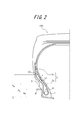
- FIG. 2 is a schematic cross-sectional view in the tire width direction showing an example of a pneumatic tire according to the present invention with respect to a tire half portion.
- a pneumatic tire 100 shown in FIG. 2 extends between the pair of bead cores 1, 1 (only one side is shown) in a toroid shape and extends from the carcass body 2 a and is wound around the bead core 1.
- a carcass 2 composed of one ply and formed of a carcass folding portion 2b is provided.
- the distance between the ply cords of the carcass main body portion 2a and the carcass folded portion 2b gradually decreases from the bead core 1 position (the outer end position in the tire radial direction of the bead core 1) toward the outer side in the tire radial direction.
- three portions 23 are examples of the distance between the ply cords of the carcass main body portion 2a and the carcass folded portion 2b gradually decreases from the bead core 1 position (the outer end position in the tire radial direction of the bead core 1) toward the outer side in the tire radial direction.
- a cutout portion 3 formed by cutting out the outer rubber toward the inner side in the tire width direction is provided in the outer rubber portion of the second portion 22 on the outer side in the tire width direction of the carcass folded portion 2b.
- the “ply cord distance (or cord distance)” means the point where a straight line perpendicular to the carcass main body intersects with the cord of the carcass main body as shown by the reference symbol x in FIG. This is the distance between the carcass folding part and the point where it intersects.
- the distance between cords takes a minimum value at the boundary position between the first portion 21 and the second portion 22 of the carcass 2.
- the carcass folded portion 2b is brought close to the carcass main body portion 2a (that is, the distance between the cords is shortened)
- the carcass folded portion 2b is disposed near the neutral axis of bending. Therefore, in the region where the carcass folded portion 2b is close to the carcass main body portion 2a, the compressive strain of the carcass folded portion 2b can be suppressed, and the fatigue fracture of the carcass folded portion 2b can be suppressed.
- the pneumatic tire 100 has a cutout portion 3 cut out toward the inner side in the tire width direction on the outer rubber portion of the carcass folding portion 2b of the second portion 22 of the carcass 2 on the outer side in the tire width direction.
- the first portion 21 of the carcass 2 that is, the bead core 1 side from the second portion 22 is a portion that contacts the rim flange when the bead portion falls down in the tire width direction during load rolling. Accordingly, when the cutout portion 3 is provided in such a portion, rim displacement is induced.
- the cutout portion 3 is provided outside the third portion 23 of the carcass 2, that is, the second portion 22 in the tire radial direction, the rubber thickness near the sidewall portion becomes unnecessarily thin, and cut resistance is reduced. The performance will be significantly reduced. Therefore, in the pneumatic tire 100, the cutout portion 3 that is cut out inward in the tire width direction is provided in the outer rubber portion of the carcass folded portion 2b of the second portion 22 of the carcass 2 in the tire width direction. In the pneumatic tire 100, by providing the notch 3 at the above-described position, it is possible to prevent the deterioration of the rubber due to heat generation or heat storage due to the thickening of the rubber in the portion without causing the above problem. it can.
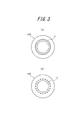
- the notch 3 may be provided continuously in the tire circumferential direction as shown in FIG. 3 (a), or may be provided intermittently in the tire circumferential direction as shown in FIG. 3 (b). Note that in the pneumatic tire of the present invention, the more the cutout portion, the more efficiently the heat generation of the rubber can be reduced, and the risk of cracking of the cutout portion can be reduced. As shown, it is preferably provided continuously in the tire circumferential direction.
- H A the distance from the rim diameter line L of the applied rim R to the boundary position between the second portion 22 and the third portion 23 is H B
- the flange height of the applied rim R is H f
- H A , H B and H f are 1.26 ⁇ H f ⁇ H A ⁇ 2.14 ⁇ H f 2.43 ⁇ H f ⁇ H B ⁇ 3.75 ⁇ H f It is preferable to satisfy the following relational expression.
- the “applicable rim” is an industrial standard effective in the region where tires are produced and used.
- JATMA Joint Automobile Tire Association
- ETRTO European Tire and Rim Technical Organization
- STANDARD MANUAL in the United States refers to the rim specified in TRA (THE TIRE and RIM ASSOCATION INC.) YEAR BOOK, etc.
- the “rim diameter line” refers to a tire width direction line passing through a position where the rim diameter is measured.
- the distance from the rim diameter line of the applicable rim to the boundary position between the first part and the second part is a straight line passing through the rim diameter line of the applicable rim, as indicated by reference numeral HA in FIG.
- the straight line passing through the boundary position between the first part and the second part passes through the point where it intersects with the cord of the carcass main body part and is the minimum between the straight line parallel to the rim diameter line Say distance.
- the “distance from the rim diameter line of the applied rim to the boundary position between the second part and the third part” passes through the rim diameter line of the applied rim, as indicated by reference numeral H B in FIG.
- the distances H A , H B , and H f indicate distances in a no-load state in which a tire is mounted on an applicable rim and a predetermined internal pressure is applied.
- the “predetermined internal pressure” refers to an internal pressure (maximum air pressure) corresponding to a tire maximum load capacity of a standard such as JATMA in a tire of an applicable size.
- HA and Hf are 1.26 ⁇ H f ⁇ H A ⁇ 2.14 ⁇ H f It is preferable to satisfy the following relational expression.
- the compressive strain acting on the carcass folded portion 2b becomes strong at the position where the distance between cords becomes the maximum value, and tensile strain is generated in the carcass folded portion 2b. As a result, the effect of reducing the compressive strain is reduced, so that it is difficult to suppress the fatigue fracture of the carcass folded portion 2b.
- the distance H B exceeds 3.75 ⁇ H f , the position where the distance between cords becomes the maximum value is too far from the region where the compressive force is applied, so that tensile strain is applied to the carcass folded portion 2b.
- the effect of reducing the compressive strain is reduced, and it becomes difficult to suppress the fatigue fracture of the carcass folded portion 2b.
- the tension applied to the carcass folded portion 2b increases in the sidewall region near the end of the carcass folded portion 2b. This tension increases the shear strain of rubber in the vicinity of the end portion of the carcass folded portion 2b, and a crack is likely to occur at the end portion of the carcass folded portion 2b.
- H B and H f are 2.43 ⁇ H f ⁇ H B ⁇ 3.75 ⁇ H f It is preferable to satisfy the following relational expression.
- the inter-cord distance a at the boundary position between the first part 21 and the second part 22 and the inter-cord distance b at the boundary position between the second part 22 and the third part 23 are: 1.40 ⁇ b / a ⁇ 4.00 It is preferable to satisfy the following relational expression. This is because the thickness of the entire bead portion is increased, and in particular, generation of separation due to heat generation or increased heat storage at the boundary position between the second portion 22 and the third portion 23 is avoided.
- the minimum thickness of the outer rubber portion of the outer portion in the tire width direction of the carcass folding portion 2b of the second portion 22 is set to the outer side in the tire width direction of the carcass folding portion 2b of the third portion 23. It is preferably larger than the minimum thickness dimension of the outer rubber part.
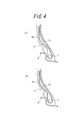
- the cross-sectional shape in the tire width direction of the notch 3 is preferably a triangular shape.
- the corner portion is formed to have a curvature.
- the cross-sectional shape in the tire width direction of the notch portion 3 is more preferably an arc shape continuous with one or more curvature radii. If the arc shape is used, it is possible to prevent the occurrence of cracks due to the corners. Furthermore, if multiple arcs are combined, the degree of freedom of the cross-sectional shape increases and the amount of rubber can be reduced more efficiently. Because it becomes.
- the cross-sectional shape in the tire width direction of the notch portion 3 may be a quadrangular shape, more specifically a trapezoidal shape as shown in FIG. 4B as an example.
- the corner portion increases, the degree of freedom of the cross-sectional shape increases, and the amount of rubber can be reduced more efficiently.
- the area of the notch 3 in the cross section in the tire width direction is preferably in the range of 5 to 30% of the area of the portion surrounded by the carcass folded portion and the tire outer surface. This is because if the area is less than 5%, the heat reduction effect of the bead portion is not sufficiently exhibited. On the other hand, if it exceeds 30%, the falling deformation of the bead portion increases, the distortion of the carcass folded portion deteriorates, and the possibility of occurrence of separation increases.
- the “part surrounded by the carcass folded portion and the tire outer surface” means a carcass folded portion and a tire outer surface formed by a smooth curve without forming a notch portion (conventional shown by a two-dot chain line in FIG. 2).
- the portion surrounded by the carcass folded portion and the tire outer surface is the distance along the tire radial direction from the rim diameter line is 1.15 times or more of the flange height H f of approved rim, and is 0.3 times the range of the tire section height SH.
- the pneumatic tire 100 can exhibit an effect more effectively when used for heavy-duty vehicles such as heavy-duty trucks and buses.
- heavy-duty vehicles such as heavy-duty trucks and buses.
- the above description shows an example of a typical embodiment, and the present invention is not limited to this embodiment.
- Example 1 A pneumatic tire having the structure shown in FIG. 2 and a tire size of 59 / 80R63 was produced.
- the produced pneumatic tire includes a ply constituted by a carcass main body portion extending in a toroid shape across a pair of bead cores, and a carcass folded portion extending from the carcass main body portion and wound around the bead core. It has a carcass.
- the carcass includes a first portion where a distance between the ply cords of the carcass main body portion and the carcass folding portion gradually decreases from the bead core position toward the outer side in the tire radial direction, and a ply cord from the first portion toward the outer side in the tire radial direction.
- the manufactured tire is provided with a notch portion that is notched inward in the tire width direction on the outer rubber portion of the second portion of the carcass folded portion on the outer side in the tire width direction. It should be noted that when the manufactured tire is mounted on the applicable rim (width: 1117.6 mm, flange height H f : 127 mm, internal pressure: 600 kPa), the first and second portions are separated from the rim diameter line of the applied rim. The distance H A to the boundary position was 1.60 ⁇ H f .
- the distance H B from the rim diameter line of the applied rim to the boundary position between the second part and the third part was 3.06 ⁇ H f .
- the cross-sectional shape in the tire width direction of the notch portion was a triangular shape and was provided continuously in the tire circumferential direction.
- the area in the tire width direction cross section of a notch part was 20% of the area of the part enclosed by a carcass folding
- the minimum thickness dimension of the outer rubber portion of the outer portion in the tire width direction of the carcass folding portion of the second portion is larger than the minimum thickness dimension of the outer rubber portion of the outer portion of the carcass folding portion of the third portion in the tire width direction. I did it.
- Example 2 A pneumatic tire was produced in the same manner as in Example 1 except that the cross-sectional shape in the tire width direction of the notch was changed to a trapezoidal shape.
- Example 3 A pneumatic tire was produced in the same manner as in Example 1 except that the cross-sectional shape in the tire width direction of the notch portion was an arc shape continuous with a radius of curvature of 1 or more.
- Example 4 A pneumatic tire was produced in the same manner as in Example 1 except that a curvature was provided at the corner of the triangular notch.
- Example 5 Except that the rim flange of the approved rim and the distance H A to the boundary position of the first and second parts and 1.25 ⁇ H f were prepared a pneumatic tire in the same manner as in Example 1.
- Example 6 Except that the rim flange of the approved rim to the first portion and the distance H A of 2.15 ⁇ H f to the boundary position of the second part, to produce a pneumatic tire in the same manner as in Example 1.
- Example 7 Except that the rim flange of the approved rim and the distance H B to the boundary position of the second portion and the third portion and 2.42 ⁇ H f were prepared a pneumatic tire in the same manner as in Example 1.
- Example 8 Except that the rim flange of the approved rim and the distance H B to the boundary position of the second portion and the third portion and 3.76 ⁇ H f were prepared a pneumatic tire in the same manner as in Example 1.
- Example 11 A pneumatic tire was produced in the same manner as in Example 1 except that the notches were intermittently provided in the tire circumferential direction.
- Example 12 A pneumatic tire was manufactured in the same manner as in Example 1 except that the area of the cutout portion in the tire width direction cross section was 3% of the area surrounded by the carcass folded portion and the tire outer surface.
- Example 13 A pneumatic tire was produced in the same manner as in Example 1 except that the area of the cutout portion in the tire width direction cross section was 33% of the area surrounded by the carcass folded portion and the tire outer surface.
- Example 14 The minimum thickness dimension of the outer rubber part of the outer part in the tire width direction of the carcass folding part of the second part is smaller than the minimum thickness dimension of the outer rubber part of the outer part of the carcass folding part of the third part in the tire width direction.
- a pneumatic tire was produced in the same manner as in Example 1.
- Example 2 A pneumatic tire was produced in the same manner as in Example 1 except that the notch was not provided.
- the bead part heat generation test and the bead part durability test were performed as follows. These results are shown in Table 1.
- the exothermic property of the bead part is the temperature of the bead part after running for 24 hours on a drum endurance tester with a drum diameter of 7 m with a drum rotation speed of 8 km / h and a drum load of 100% of the normal load of 996.4 kN.
- a thermocouple was inserted through a narrow hole provided in advance at a position where the distance between cords was a minimum value, and the temperature of the carcass folded portion 5 mm laterally was measured at three locations on the circumference.
- the durability of the bead portion was evaluated by a step load method with a drum durability tester having a drum diameter of 7 m, a drum rotation speed of 8 km / h, and a drum load of 150 to 180% of a normal load of 996.4 kN. .
- the step load method means that when a drum load is applied to a pneumatic tire to be measured for 12 hours, the start time is set to 150% of the normal load, and thereafter, the load to be applied is set to 10% of the normal load. In this method, 180% of the normal load is finally applied while increasing. Then, the evaluation of Comparative Example 1 (the sum of the products of the applied loads and the travel time at each load) was set to 100, and each was displayed as an index (the higher the index, the better the performance).
- the temperature reduction range of the bead part is larger than that of Comparative Examples 1 and 2, and the durability of the bead part is also good. .
- the second portion of the carcass in which the intercord distance gradually increases in the pneumatic tire in which the distance between the ply cords of the carcass main body portion and the carcass folding portion is appropriately controlled from the bead core position toward the outer side in the tire radial direction.
- Heat generation due to rubber thickening without lowering other performance such as anti-cut performance by providing a cutout part notched inward in the tire width direction on the outer rubber part of the folded part on the outer side in the tire width direction It is possible to prevent the deterioration of rubber due to heat storage.
Landscapes
- Engineering & Computer Science (AREA)
- Mechanical Engineering (AREA)
- Tires In General (AREA)
Abstract
Description
(1)一対のビードコア間に跨ってトロイド状に延びるカーカス本体部と、該カーカス本体部から延びてビードコアの周りに巻き返されるカーカス折返し部とで構成されるプライからなるカーカスを具える空気入りタイヤであって、前記カーカスは、ビードコア位置からタイヤ径方向外側に向かって、前記カーカス本体部と前記カーカス折返し部のプライコード間距離が漸減する第1部分と、該第1部分からタイヤ径方向外側に向かって、前記プライコード間距離が漸増する第2部分と、該第2部分からタイヤ径方向外側に向かって、前記プライコード間距離が漸減する第3部分とを有し、前記第2部分の前記カーカス折返し部のタイヤ幅方向外側の外皮ゴム部分に、タイヤ幅方向内側へ向かって切り欠いた切欠部を設けることを特徴とする空気入りタイヤ。
1.26×Hf≦HA≦2.14×Hf
2.43×Hf≦HB≦3.75×Hf
の関係式を満たす上記(1)に記載の空気入りタイヤ。
1.40≦b/a≦4.00
の関係式を満たす上記(1)または(2)に記載の空気入りタイヤ。
1.26×Hf≦HA≦2.14×Hf
2.43×Hf≦HB≦3.75×Hf
の関係式を満たすのが好ましい。
更に、「適用リムのリム径ラインから、第1部分と第2部分との境界位置までの距離」とは、図2に参照符号HAで示すように、適用リムのリム径ラインを通る直線と、第1部分および第2部分の境界位置(コード間距離が極小値となる位置)を通る直線がカーカス本体部のコードと交わる点を通ってリム径ラインに平行な直線との間の最小距離をいう。
同様に、「適用リムのリム径ラインから、第2部分と第3部分との境界位置までの距離」とは、図2に参照符号HBで示すように、適用リムのリム径ラインを通る直線と、第2部分および第3部分の境界位置(上記コード間距離が極大値となる位置)を通る直線がカーカス本体部のコードと交わる点を通ってリム径ラインに平行な直線との間の最小距離をいう。
なお、各距離HA、HB、Hfは、タイヤを適用リムに装着し、所定内圧を適用した無負荷状態における距離を指す。因みに、「所定内圧」とは、適用サイズのタイヤにおけるJATMA等の規格のタイヤ最大負荷能力に対応する内圧(最高空気圧)を指す。
1.26×Hf≦HA≦2.14×Hf
の関係式を満たすのが好ましい。
2.43×Hf≦HB≦3.75×Hf
の関係式を満たすのが好ましい。
1.40≦b/a≦4.00
の関係式を満たすのが好ましい。ビード部全体の厚みが厚くなり、特に第2部分22と第3部分23との境界位置における発熱や蓄熱の増加によるセパレーションの発生を回避するためである。
なお、「カーカス折返し部とタイヤ外面とで囲まれる部分」とは、カーカス折返し部と、切欠部を形成することなく滑らかな曲線で形成したタイヤ外表面(図2に二点鎖線で示す、従来のタイヤ外面)とで囲まれる部分を指す。因みに、リム径ラインからカーカス折返し部のタイヤ径方向外端までのタイヤ径方向に沿う距離がタイヤ断面高さSHの0.3倍以上の場合、「カーカス折返し部とタイヤ外面とで囲まれる部分」は、リム径ラインからのタイヤ径方向に沿う距離が、適用リムのフランジ高さHfの1.15倍以上、且つ、タイヤ断面高さSHの0.3倍以下の範囲とする。
図2に示す構造を有し、タイヤサイズが59/80R63の空気入りタイヤを作製した。ここで、作製した空気入りタイヤは、一対のビードコア間に跨ってトロイド状に延びるカーカス本体部と、カーカス本体部から延びてビードコアの周りに巻き返されるカーカス折返し部とで構成されるプライからなるカーカスを具えている。そして、該カーカスは、ビードコア位置からタイヤ径方向外側に向かってカーカス本体部と該カーカス折返し部のプライコード間距離が漸減する第1部分と、第1部分からタイヤ径方向外側に向かってプライコード間距離が漸増する第2部分と、第2部分からタイヤ径方向外側に向かってプライコード間距離が漸減する第3部分とを有している。更に、作製したタイヤは、第2部分のカーカス折返し部のタイヤ幅方向外側の外皮ゴム部分に、タイヤ幅方向内側へ向かって切り欠いた切欠部が設けられている。
なお、作製したタイヤを適用リム(幅:1117.6mm、フランジ高さHf:127mm、内圧:600kPa)に装着した際の、適用リムのリム径ラインから、第1部分と第2部分との境界位置までの距離HAは、1.60×Hfであった。また、適用リムのリム径ラインから、第2部分と第3部分との境界位置までの距離HBは3.06×Hfであった。
また、第1部分および第2部分の境界位置におけるコード間距離aと、第2部分および第3部分の境界位置におけるコード間距離bとの比(b/a)は、b/a=2.95であった。
なお、切欠部のタイヤ幅方向断面形状は三角形形状とし、タイヤ周方向に連続して設けた。そして、切欠部のタイヤ幅方向断面における面積は、カーカス折返し部とタイヤ外面とで囲まれる部分の面積の20%とした。
また、第2部分のカーカス折返し部のタイヤ幅方向外側の外皮ゴム部分の最小厚さ寸法は、第3部分のカーカス折返し部のタイヤ幅方向外側の外皮ゴム部分の最小厚さ寸法よりも大きくなるようにした。
切欠部のタイヤ幅方向断面形状を台形形状とした以外は、実施例1と同様にして空気入りタイヤを作製した。
切欠部のタイヤ幅方向断面形状を1以上の曲率半径で連なる円弧形状とした以外は、実施例1と同様にして空気入りタイヤを作製した。
三角形形状の切欠部の角部に曲率を設けた以外は、実施例1と同様にして空気入りタイヤを作製した。
適用リムのリムフランジから第1部分および第2部分の境界位置までの距離HAを1.25×Hfとした以外は、実施例1と同様にして空気入りタイヤを作製した。
適用リムのリムフランジから第1部分および第2部分の境界位置までの距離HAを2.15×Hfとした以外は、実施例1と同様にして空気入りタイヤを作製した。
適用リムのリムフランジから第2部分および第3部分の境界位置までの距離HBを2.42×Hfとした以外は、実施例1と同様にして空気入りタイヤを作製した。
適用リムのリムフランジから第2部分および第3部分の境界位置までの距離HBを3.76×Hfとした以外は、実施例1と同様にして空気入りタイヤを作製した。
第1部分および第2部分の境界位置におけるコード間距離aと、第2部分および第3部分の境界位置におけるコード間距離bとの比(b/a)をb/a=1.39とした以外は、実施例1と同様にして空気入りタイヤを作製した。
第1部分および第2部分の境界位置におけるコード間距離aと、第2部分および第3部分の境界位置におけるコード間距離bとの比(b/a)をb/a=4.01とした以外は、実施例1と同様にして空気入りタイヤを作製した。
切欠部をタイヤ周方向に断続的に設けた以外は、実施例1と同様にして空気入りタイヤを作製した。
切欠部のタイヤ幅方向断面における面積を、カーカス折返し部とタイヤ外面とで囲まれる部分の面積の3%とした以外は、実施例1と同様にして空気入りタイヤを作製した。
切欠部のタイヤ幅方向断面における面積を、カーカス折返し部とタイヤ外面とで囲まれる部分の面積の33%とした以外は、実施例1と同様にして空気入りタイヤを作製した。
第2部分のカーカス折返し部のタイヤ幅方向外側の外皮ゴム部分の最小厚さ寸法を、第3部分のカーカス折返し部のタイヤ幅方向外側の外皮ゴム部分の最小厚さ寸法よりも小さくした以外は、実施例1と同様にして空気入りタイヤを作製した。
第1部分および第2部分の境界位置におけるコード間距離aと、第2部分および第3部分の境界位置におけるコード間距離bとの比(b/a)をb/a=1.00としてコード間距離を一定にし、切欠部を設けなかった以外は、実施例1と同様にして空気入りタイヤを作製した。
切欠部を設けなかった以外は、実施例1と同様にして空気入りタイヤを作製した。
(発熱試験)
ビード部の発熱性は、ドラム径が7mのドラム耐久試験機にて、ドラム回転速度を8km/hとし、ドラム荷重を正規荷重996.4kNの100%として24時間走行した後のビード部の温度を測定して評価した。具体的には、走行後に、コード間距離が極小値となる位置に予め設けておいた細穴から熱電対を挿入し、カーカス折返し部横5mmの温度を周上の3箇所で測定した。そして、測定された温度の平均値を求め、比較例1の温度との差(温度低減幅)を求めてそれぞれ比較した。
(耐久試験)
ビード部の耐久性は、ドラム径が7mのドラム耐久試験機にて、ドラム回転速度を8km/hとし、ドラム荷重を正規荷重996.4kNの150~180%として、ステップロード方式にて評価した。なお、ステップロード方式とは、測定対象の空気入りタイヤに対して12時間にわたりドラム荷重を負荷する際に、スタート時を正規荷重の150%とし、以後、負荷する荷重を正規荷重の10%ずつ増加させながら、最終的には正規荷重の180%を負荷する方式である。そして、比較例1の評価(負荷した各荷重と各荷重での走行時間との積の総和)を100として、各々を指数表示した(指数は大きいほど良性能であることを示す)。

1 ビードコア
2 カーカス
2a カーカス本体部
2b カーカス折返し部
3 切欠部
21 第1部分
22 第2部分
23 第3部分
Claims (7)
- 一対のビードコア間に跨ってトロイド状に延びるカーカス本体部と、該カーカス本体部から延びてビードコアの周りに巻き返されるカーカス折返し部とで構成されるプライからなるカーカスを具える空気入りタイヤであって、前記カーカスは、
ビードコア位置からタイヤ径方向外側に向かって、前記カーカス本体部と前記カーカス折返し部のプライコード間距離が漸減する第1部分と、
該第1部分からタイヤ径方向外側に向かって、前記プライコード間距離が漸増する第2部分と、
該第2部分からタイヤ径方向外側に向かって、前記プライコード間距離が漸減する第3部分とを有し、
前記第2部分の前記カーカス折返し部のタイヤ幅方向外側の外皮ゴム部分に、タイヤ幅方向内側へ向かって切り欠いた切欠部を設けることを特徴とする空気入りタイヤ。 - タイヤを適用リムに装着した際に、
前記適用リムのリム径ラインから、前記第1部分と前記第2部分との境界位置までの距離をHA、
前記適用リムのリム径ラインから、前記第2部分と前記第3部分との境界位置までの距離をHB、
前記適用リムのフランジ高さをHfとしたとき、HA、HBおよびHfが、
1.26×Hf≦HA≦2.14×Hf
2.43×Hf≦HB≦3.75×Hf
の関係式を満たす請求項1に記載の空気入りタイヤ。 - 前記第1部分と前記第2部分との境界位置におけるプライコード間距離aと、前記第2部分と前記第3部分との境界位置におけるプライコード間距離bとが、
1.40≦b/a≦4.00
の関係式を満たす請求項1または2に記載の空気入りタイヤ。 - 前記第2部分の前記カーカス折返し部のタイヤ幅方向外側の外皮ゴム部分の最小厚さ寸法は、前記第3部分の前記カーカス折返し部のタイヤ幅方向外側の外皮ゴム部分の最小厚さ寸法よりも大きい請求項1、2または3に記載の空気入りタイヤ。
- 前記切欠部のタイヤ幅方向断面形状が三角形形状である請求項1~4のいずれか一項に記載の空気入りタイヤ。
- 前記切欠部のタイヤ幅方向断面形状が台形形状である請求項1~4のいずれか一項に記載の空気入りタイヤ。
- 前記切欠部のタイヤ幅方向断面形状が1以上の曲率半径で連なる円弧形状である請求項1~4のいずれか一項に記載の空気入りタイヤ。
Priority Applications (6)
| Application Number | Priority Date | Filing Date | Title |
|---|---|---|---|
| BR112013002687-1A BR112013002687B1 (pt) | 2010-08-05 | 2011-08-04 | Pneumático |
| US13/813,439 US8863800B2 (en) | 2010-08-05 | 2011-08-04 | Pneumatic tire with specified carcass folded section and notched portion |
| ES11814308.0T ES2616804T3 (es) | 2010-08-05 | 2011-08-04 | Neumático |
| EP11814308.0A EP2602129B1 (en) | 2010-08-05 | 2011-08-04 | Pneumatic tire |
| CN201180047901.0A CN103140362B (zh) | 2010-08-05 | 2011-08-04 | 充气轮胎 |
| JP2012527606A JP5722899B2 (ja) | 2010-08-05 | 2011-08-04 | 空気入りタイヤ |
Applications Claiming Priority (2)
| Application Number | Priority Date | Filing Date | Title |
|---|---|---|---|
| JP2010176414 | 2010-08-05 | ||
| JP2010-176414 | 2010-08-05 |
Publications (1)
| Publication Number | Publication Date |
|---|---|
| WO2012017673A1 true WO2012017673A1 (ja) | 2012-02-09 |
Family
ID=45559192
Family Applications (1)
| Application Number | Title | Priority Date | Filing Date |
|---|---|---|---|
| PCT/JP2011/004446 Ceased WO2012017673A1 (ja) | 2010-08-05 | 2011-08-04 | 空気入りタイヤ |
Country Status (7)
| Country | Link |
|---|---|
| US (1) | US8863800B2 (ja) |
| EP (1) | EP2602129B1 (ja) |
| JP (1) | JP5722899B2 (ja) |
| CN (1) | CN103140362B (ja) |
| BR (1) | BR112013002687B1 (ja) |
| ES (1) | ES2616804T3 (ja) |
| WO (1) | WO2012017673A1 (ja) |
Cited By (5)
| Publication number | Priority date | Publication date | Assignee | Title |
|---|---|---|---|---|
| US20130327460A1 (en) * | 2011-03-07 | 2013-12-12 | Bridgestone Corporation | Pneumatic tire |
| WO2014090862A1 (fr) * | 2012-12-13 | 2014-06-19 | Compagnie Generale Des Etablissements Michelin | Bourrelet de pneumatique pour vehicule lourd de type genie civil |
| WO2016093126A1 (ja) * | 2014-12-10 | 2016-06-16 | 株式会社ブリヂストン | 建設車両用タイヤ |
| US10226969B2 (en) * | 2013-02-22 | 2019-03-12 | Bridgestone Corporation | Heavy load tire with curved sidewall recess |
| DE102024108007A1 (de) * | 2024-03-20 | 2025-09-25 | Continental Reifen Deutschland Gmbh | Fahrzeugreifen |
Families Citing this family (5)
| Publication number | Priority date | Publication date | Assignee | Title |
|---|---|---|---|---|
| CN104354540A (zh) * | 2014-10-13 | 2015-02-18 | 王友善 | 一种全钢丝三角胶外置的无内胎子午线轮胎 |
| JP6785104B2 (ja) * | 2015-10-02 | 2020-11-18 | 株式会社ブリヂストン | 建設車両用タイヤ |
| WO2017057705A1 (ja) * | 2015-10-02 | 2017-04-06 | 株式会社ブリヂストン | 建設車両用タイヤ |
| JP7183689B2 (ja) * | 2018-10-22 | 2022-12-06 | 住友ゴム工業株式会社 | 重荷重用空気入りタイヤ |
| CN113910840A (zh) * | 2020-07-08 | 2022-01-11 | 正新橡胶工业股份有限公司 | 具有车轮保护装置的轮胎、车轮保护装置及车轮保护方法 |
Citations (4)
| Publication number | Priority date | Publication date | Assignee | Title |
|---|---|---|---|---|
| JPH09309303A (ja) * | 1996-05-23 | 1997-12-02 | Bridgestone Corp | 重荷重用空気入りバイアスタイヤ |
| WO2007032405A1 (ja) * | 2005-09-13 | 2007-03-22 | Bridgestone Corporation | 空気入りタイヤ |
| JP2007191090A (ja) * | 2006-01-20 | 2007-08-02 | Yokohama Rubber Co Ltd:The | 空気入りタイヤ |
| JP2007196781A (ja) | 2006-01-25 | 2007-08-09 | Bridgestone Corp | 空気入りタイヤ |
Family Cites Families (13)
| Publication number | Priority date | Publication date | Assignee | Title |
|---|---|---|---|---|
| JPH04218414A (ja) * | 1990-12-19 | 1992-08-10 | Bridgestone Corp | 空気入りタイヤ |
| DE69910523T2 (de) * | 1998-10-29 | 2004-03-18 | Sumitomo Rubber Industries Ltd., Kobe | Reifen |
| JP4450449B2 (ja) * | 1999-04-23 | 2010-04-14 | 株式会社ブリヂストン | 空気入りラジアルタイヤ |
| ES2242578T3 (es) | 1999-01-28 | 2005-11-16 | Bridgestone Corporation | Cubierta neumatica. |
| JP2000225816A (ja) * | 1999-02-02 | 2000-08-15 | Bridgestone Corp | 空気入りタイヤ |
| JP4263939B2 (ja) * | 2003-04-08 | 2009-05-13 | 住友ゴム工業株式会社 | 空気入りタイヤ |
| JP4723200B2 (ja) * | 2004-03-25 | 2011-07-13 | 住友ゴム工業株式会社 | ランフラットタイヤ |
| JP2006069290A (ja) * | 2004-08-31 | 2006-03-16 | Bridgestone Corp | 空気入りラジアルタイヤ |
| JP2006199066A (ja) * | 2005-01-18 | 2006-08-03 | Bridgestone Corp | 空気入りタイヤ |
| JP4604868B2 (ja) * | 2005-06-17 | 2011-01-05 | 横浜ゴム株式会社 | 空気入りタイヤ |
| EP2581239A1 (en) * | 2006-01-20 | 2013-04-17 | The Yokohama Rubber Co., Ltd. | Pneumatic tire |
| JP5216304B2 (ja) | 2007-11-08 | 2013-06-19 | 株式会社ブリヂストン | 建設車両用空気入りタイヤ |
| JP5399778B2 (ja) * | 2009-05-29 | 2014-01-29 | 株式会社ブリヂストン | 空気入りタイヤ |
-
2011
- 2011-08-04 JP JP2012527606A patent/JP5722899B2/ja not_active Expired - Fee Related
- 2011-08-04 US US13/813,439 patent/US8863800B2/en active Active
- 2011-08-04 EP EP11814308.0A patent/EP2602129B1/en not_active Not-in-force
- 2011-08-04 WO PCT/JP2011/004446 patent/WO2012017673A1/ja not_active Ceased
- 2011-08-04 BR BR112013002687-1A patent/BR112013002687B1/pt not_active IP Right Cessation
- 2011-08-04 CN CN201180047901.0A patent/CN103140362B/zh not_active Expired - Fee Related
- 2011-08-04 ES ES11814308.0T patent/ES2616804T3/es active Active
Patent Citations (4)
| Publication number | Priority date | Publication date | Assignee | Title |
|---|---|---|---|---|
| JPH09309303A (ja) * | 1996-05-23 | 1997-12-02 | Bridgestone Corp | 重荷重用空気入りバイアスタイヤ |
| WO2007032405A1 (ja) * | 2005-09-13 | 2007-03-22 | Bridgestone Corporation | 空気入りタイヤ |
| JP2007191090A (ja) * | 2006-01-20 | 2007-08-02 | Yokohama Rubber Co Ltd:The | 空気入りタイヤ |
| JP2007196781A (ja) | 2006-01-25 | 2007-08-09 | Bridgestone Corp | 空気入りタイヤ |
Non-Patent Citations (1)
| Title |
|---|
| See also references of EP2602129A4 |
Cited By (10)
| Publication number | Priority date | Publication date | Assignee | Title |
|---|---|---|---|---|
| US20130327460A1 (en) * | 2011-03-07 | 2013-12-12 | Bridgestone Corporation | Pneumatic tire |
| US9056528B2 (en) * | 2011-03-07 | 2015-06-16 | Bridgestone Corporation | Pneumatic tire with specified carcass ply turn-back portions |
| WO2014090862A1 (fr) * | 2012-12-13 | 2014-06-19 | Compagnie Generale Des Etablissements Michelin | Bourrelet de pneumatique pour vehicule lourd de type genie civil |
| FR2999474A1 (fr) * | 2012-12-13 | 2014-06-20 | Michelin & Cie | Bourrelet de pneumatique pour vehicule lourd de type genie civil |
| JP2015536869A (ja) * | 2012-12-13 | 2015-12-24 | コンパニー ゼネラール デ エタブリッスマン ミシュラン | 建設プラントタイプの大型車両用タイヤのビード部 |
| CN104853937B (zh) * | 2012-12-13 | 2017-01-18 | 米其林集团总公司 | 用于施工场地类型的重型车辆的轮胎的胎圈 |
| US9796218B2 (en) | 2012-12-13 | 2017-10-24 | Compagnie Generale Des Etablissements Michelin | Bead of a tire for a heavy vehicle of the construction plant type |
| US10226969B2 (en) * | 2013-02-22 | 2019-03-12 | Bridgestone Corporation | Heavy load tire with curved sidewall recess |
| WO2016093126A1 (ja) * | 2014-12-10 | 2016-06-16 | 株式会社ブリヂストン | 建設車両用タイヤ |
| DE102024108007A1 (de) * | 2024-03-20 | 2025-09-25 | Continental Reifen Deutschland Gmbh | Fahrzeugreifen |
Also Published As
| Publication number | Publication date |
|---|---|
| ES2616804T3 (es) | 2017-06-14 |
| CN103140362B (zh) | 2015-07-15 |
| BR112013002687B1 (pt) | 2021-10-26 |
| US8863800B2 (en) | 2014-10-21 |
| JP5722899B2 (ja) | 2015-05-27 |
| EP2602129A4 (en) | 2014-04-23 |
| BR112013002687A2 (pt) | 2016-05-31 |
| CN103140362A (zh) | 2013-06-05 |
| EP2602129B1 (en) | 2017-01-04 |
| JPWO2012017673A1 (ja) | 2013-10-03 |
| US20130192738A1 (en) | 2013-08-01 |
| EP2602129A1 (en) | 2013-06-12 |
Similar Documents
| Publication | Publication Date | Title |
|---|---|---|
| JP5722899B2 (ja) | 空気入りタイヤ | |
| JP5750156B2 (ja) | 空気入りタイヤ | |
| JP6386726B2 (ja) | 重荷重用タイヤ | |
| JP5628946B2 (ja) | 重荷重用タイヤ | |
| WO2015159468A1 (ja) | ランフラットタイヤ | |
| JP5745539B2 (ja) | 空気入りタイヤ | |
| JP6454181B2 (ja) | 重荷重用空気入りタイヤ及びその製造方法 | |
| WO2014188938A1 (ja) | 空気入りタイヤ | |
| WO2013105309A1 (ja) | 重荷重用空気入りタイヤ | |
| JP2011162023A (ja) | 空気入りタイヤ | |
| JP2010111370A (ja) | 空気入りタイヤ | |
| JP2015205583A (ja) | サイド補強型ランフラットラジアルタイヤ | |
| WO2016024391A1 (ja) | 空気入りタイヤ | |
| JP4703644B2 (ja) | 重荷重用空気入りタイヤ | |
| JP5852031B2 (ja) | 空気入りタイヤ | |
| JP4724103B2 (ja) | 重荷重用空気入りラジアルタイヤ | |
| JP5331535B2 (ja) | 重荷重用空気入りラジアルタイヤ | |
| WO2016051685A1 (ja) | 重荷重用空気入りタイヤ | |
| JP5990384B2 (ja) | 空気入りタイヤ | |
| JP6294210B2 (ja) | 空気入りタイヤ | |
| WO2016024390A1 (ja) | 空気入りタイヤ | |
| JP6438269B2 (ja) | 空気入りタイヤ | |
| JP6462271B2 (ja) | 空気入りタイヤ | |
| WO2025079466A1 (ja) | 空気入りタイヤ | |
| JP5469906B2 (ja) | 空気入りタイヤ |
Legal Events
| Date | Code | Title | Description |
|---|---|---|---|
| WWE | Wipo information: entry into national phase |
Ref document number: 201180047901.0 Country of ref document: CN |
|
| 121 | Ep: the epo has been informed by wipo that ep was designated in this application |
Ref document number: 11814308 Country of ref document: EP Kind code of ref document: A1 |
|
| WWE | Wipo information: entry into national phase |
Ref document number: 2012527606 Country of ref document: JP |
|
| REEP | Request for entry into the european phase |
Ref document number: 2011814308 Country of ref document: EP |
|
| WWE | Wipo information: entry into national phase |
Ref document number: 2011814308 Country of ref document: EP |
|
| NENP | Non-entry into the national phase |
Ref country code: DE |
|
| WWE | Wipo information: entry into national phase |
Ref document number: 13813439 Country of ref document: US |
|
| REG | Reference to national code |
Ref country code: BR Ref legal event code: B01A Ref document number: 112013002687 Country of ref document: BR |
|
| ENP | Entry into the national phase |
Ref document number: 112013002687 Country of ref document: BR Kind code of ref document: A2 Effective date: 20130204 |