WO2012017804A1 - 圧着端子 - Google Patents
圧着端子 Download PDFInfo
- Publication number
- WO2012017804A1 WO2012017804A1 PCT/JP2011/066189 JP2011066189W WO2012017804A1 WO 2012017804 A1 WO2012017804 A1 WO 2012017804A1 JP 2011066189 W JP2011066189 W JP 2011066189W WO 2012017804 A1 WO2012017804 A1 WO 2012017804A1
- Authority
- WO
- WIPO (PCT)
- Prior art keywords
- conductor
- terminal
- crimping
- bottom plate
- conductor crimping
- Prior art date
- Legal status (The legal status is an assumption and is not a legal conclusion. Google has not performed a legal analysis and makes no representation as to the accuracy of the status listed.)
- Ceased
Links
Images


Classifications
-
- H—ELECTRICITY
- H01—ELECTRIC ELEMENTS
- H01R—ELECTRICALLY-CONDUCTIVE CONNECTIONS; STRUCTURAL ASSOCIATIONS OF A PLURALITY OF MUTUALLY-INSULATED ELECTRICAL CONNECTING ELEMENTS; COUPLING DEVICES; CURRENT COLLECTORS
- H01R4/00—Electrically-conductive connections between two or more conductive members in direct contact, i.e. touching one another; Means for effecting or maintaining such contact; Electrically-conductive connections having two or more spaced connecting locations for conductors and using contact members penetrating insulation
- H01R4/10—Electrically-conductive connections between two or more conductive members in direct contact, i.e. touching one another; Means for effecting or maintaining such contact; Electrically-conductive connections having two or more spaced connecting locations for conductors and using contact members penetrating insulation effected solely by twisting, wrapping, bending, crimping, or other permanent deformation
- H01R4/18—Electrically-conductive connections between two or more conductive members in direct contact, i.e. touching one another; Means for effecting or maintaining such contact; Electrically-conductive connections having two or more spaced connecting locations for conductors and using contact members penetrating insulation effected solely by twisting, wrapping, bending, crimping, or other permanent deformation by crimping
- H01R4/188—Electrically-conductive connections between two or more conductive members in direct contact, i.e. touching one another; Means for effecting or maintaining such contact; Electrically-conductive connections having two or more spaced connecting locations for conductors and using contact members penetrating insulation effected solely by twisting, wrapping, bending, crimping, or other permanent deformation by crimping having an uneven wire-receiving surface to improve the contact
-
- H—ELECTRICITY
- H01—ELECTRIC ELEMENTS
- H01R—ELECTRICALLY-CONDUCTIVE CONNECTIONS; STRUCTURAL ASSOCIATIONS OF A PLURALITY OF MUTUALLY-INSULATED ELECTRICAL CONNECTING ELEMENTS; COUPLING DEVICES; CURRENT COLLECTORS
- H01R4/00—Electrically-conductive connections between two or more conductive members in direct contact, i.e. touching one another; Means for effecting or maintaining such contact; Electrically-conductive connections having two or more spaced connecting locations for conductors and using contact members penetrating insulation
- H01R4/28—Clamped connections, spring connections
-
- H—ELECTRICITY
- H01—ELECTRIC ELEMENTS
- H01R—ELECTRICALLY-CONDUCTIVE CONNECTIONS; STRUCTURAL ASSOCIATIONS OF A PLURALITY OF MUTUALLY-INSULATED ELECTRICAL CONNECTING ELEMENTS; COUPLING DEVICES; CURRENT COLLECTORS
- H01R4/00—Electrically-conductive connections between two or more conductive members in direct contact, i.e. touching one another; Means for effecting or maintaining such contact; Electrically-conductive connections having two or more spaced connecting locations for conductors and using contact members penetrating insulation
- H01R4/10—Electrically-conductive connections between two or more conductive members in direct contact, i.e. touching one another; Means for effecting or maintaining such contact; Electrically-conductive connections having two or more spaced connecting locations for conductors and using contact members penetrating insulation effected solely by twisting, wrapping, bending, crimping, or other permanent deformation
- H01R4/18—Electrically-conductive connections between two or more conductive members in direct contact, i.e. touching one another; Means for effecting or maintaining such contact; Electrically-conductive connections having two or more spaced connecting locations for conductors and using contact members penetrating insulation effected solely by twisting, wrapping, bending, crimping, or other permanent deformation by crimping
- H01R4/183—Electrically-conductive connections between two or more conductive members in direct contact, i.e. touching one another; Means for effecting or maintaining such contact; Electrically-conductive connections having two or more spaced connecting locations for conductors and using contact members penetrating insulation effected solely by twisting, wrapping, bending, crimping, or other permanent deformation by crimping for cylindrical elongated bodies, e.g. cables having circular cross-section
- H01R4/184—Electrically-conductive connections between two or more conductive members in direct contact, i.e. touching one another; Means for effecting or maintaining such contact; Electrically-conductive connections having two or more spaced connecting locations for conductors and using contact members penetrating insulation effected solely by twisting, wrapping, bending, crimping, or other permanent deformation by crimping for cylindrical elongated bodies, e.g. cables having circular cross-section comprising a U-shaped wire-receiving portion
- H01R4/185—Electrically-conductive connections between two or more conductive members in direct contact, i.e. touching one another; Means for effecting or maintaining such contact; Electrically-conductive connections having two or more spaced connecting locations for conductors and using contact members penetrating insulation effected solely by twisting, wrapping, bending, crimping, or other permanent deformation by crimping for cylindrical elongated bodies, e.g. cables having circular cross-section comprising a U-shaped wire-receiving portion combined with a U-shaped insulation-receiving portion
Definitions
- the present invention relates to an open barrel type crimp terminal having a conductor crimping portion having a U-shaped cross section used in, for example, an electrical system of an automobile.
- FIG. 1 is a perspective view showing a configuration of a related crimp terminal described in Patent Document 1, for example.
- the crimp terminal 101 includes an electrical connection portion 110 connected to a terminal on the mating connector side at a front portion in a longitudinal direction of the terminal (which is also a longitudinal direction of a conductor of a wire to be connected), and an electrical wire (not shown) at a rear portion thereof. ) Is provided with a conductor crimping portion 111 that is crimped to the exposed conductor of the terminal, and further, a covering crimping portion 112 that is crimped to a portion of the electric wire with an insulating coating is provided. Between the electrical connection part 110 and the conductor crimping
- the conductor crimping portion 111 includes a bottom plate 111A and a pair of conductor crimping pieces 111B and 111B that are extended upward from the left and right side edges of the bottom plate 111A and are crimped so as to wrap the conductor of the electric wire disposed on the inner surface of the bottom plate 111A.
- the covering caulking portion 112 is a pair of caulking so as to wrap the bottom plate 112A and electric wires (parts with an insulating coating) that extend upward from the left and right side edges of the bottom plate 112A and are arranged on the inner surface of the bottom plate 112A.
- the covering caulking pieces 112B and 112B are formed in a substantially U-shaped cross section.
- the first connecting portion 113 and the second connecting portion 114 before and after the conductor crimping portion 111 are both bottom plates 113A and 114A and low-profile side plates 113B and 114B that stand up from the left and right edges of the bottom plates 113A and 114A. And a U-shaped cross section.
- the bottom plate (the bottom plate 113A of the first connecting portion 113, the bottom plate 111A of the conductor crimping portion 111, the second plate) in the range from the bottom plate (not shown) of the front electrical connecting portion 110 to the last covering crimping portion 112.
- the bottom plate 114A of the connecting portion 114 and the bottom plate 112A of the cover crimping portion 112 are continuously formed in a single strip shape.
- the front and rear ends of the low-profile side plate 113B of the first connecting portion 113 are the lower half portions of the rear end of the side plate (reference number omitted) of the electrical connection portion 110 and the front end of the conductor crimping piece 111B of the conductor crimping portion 111.
- the front and rear ends of the low-side side plate 114B of the second connecting portion 114 are the rear end of the conductor crimping piece 111B of the conductor crimping portion 111 and the front end of the covering crimping piece 112B of the covering crimping portion 112, respectively.
- Each lower half is continuous.
- the inner surface 111R on the side in contact with the conductor of the electric wire has a plurality of groove-shaped serrations extending in a direction orthogonal to the direction in which the conductor of the electric wire extends (terminal longitudinal direction). 120 is provided.
- FIG. 2 is a detailed view of the serration 120 formed on the inner surface of the conductor crimping portion 111.
- FIG. 2 (a) is a plan view showing the conductor crimping portion 111 in an expanded state
- FIG. 2 (b) is FIG. 2 (a).
- FIG. 2 (c) is an enlarged view of the IIc portion of FIG. 2 (b).
- the cross-sectional shape of the groove-shaped serration 120 is rectangular or inverted trapezoidal, and the inner bottom surface 120A is formed substantially parallel to the outer surface 111S of the conductor crimping portion 111.
- the inner corner 120C where the inner side surface 120B and the inner bottom surface 120A intersect is formed as an angular part where the plane and the plane intersect, and the hole edge 120D where the inner side surface 120B and the inner surface 111R of the conductor crimping part 111 intersect is formed as an angular edge. ing.
- the crimp terminal 101 In order to crimp the conductor crimping portion 111 of the crimp terminal 101 to the conductor at the end of the electric wire, the crimp terminal 101 is placed on the mounting surface (upper surface) of the lower mold (anvil) (not shown) and the conductor at the end of the electric wire is attached. It is inserted between the conductor crimping pieces 111A of the conductor crimping part 111 and placed on the upper surface of the bottom plate 111A. Then, by lowering the upper mold (crimper) relative to the lower mold, the leading end side of the conductor crimping piece 111B is gradually tilted inward on the upper mold guide slope.
- the tip of the conductor crimping piece 111B is formed with a curved surface extending from the guide slope of the upper mold to the central chevron.
- the conductor crimping piece 111B is crimped so as to wrap the conductor by rolling it back to the conductor side and biting into the conductor while rubbing the tips of the conductor crimping pieces 111B.
- the conductor crimping portion 111 of the crimp terminal 101 can be connected to the conductor of the electric wire by crimping.
- the covering crimping portion 112 is also bent gradually inward using the lower mold and the upper mold, and the covering crimping piece 112B is applied to the portion of the electric wire with the insulation coating. Tighten. By doing so, the crimp terminal 101 can be electrically and mechanically connected to the electric wire.
- the conductor of the electric wire enters the serration 120 on the inner surface of the conductor crimping portion 111 while being plastically deformed by the applied pressure, thereby strengthening the bonding between the terminal 101 and the electric wire.
- the groove 111 is provided on the inner surface 111R of the conductor crimping portion 111 so as to be orthogonal to the direction in which the electric wire extends, but sufficient contact conductivity is not always obtained.
- the conductor crimping portion 111 is crimped to the conductor of the electric wire, the surface of the conductor that flows due to the pressing force and the edge of the serration rub against each other, or the surface of the conductor that enters the serration and the inner surface of the serration As a result, the oxide film on the surface of the conductor is peeled off, and the exposed new surface is brought into contact with the terminal.
- the related serration 120 is linear, it is effective when the conductor of the wire flows in the longitudinal direction of the terminal, but for the extension of the conductor in other directions It was not very effective.
- the inner corner 120C where the inner bottom surface 120A and the inner side surface 120B of the serration 120 intersect each other is angular, the conductor Wa that has entered the serration 120 has its inner corner 120C.
- the gap 150 was likely to occur in the inner corner 120C. Therefore, when the gap 150 is large, an oxide film grows from the gap 150 due to the influence of thermal shock, mechanical vibration, etc., and the contact conductivity between the conductor Wa and the terminal 101 decreases. There was a risk.
- An object of the present invention is to provide a crimp terminal capable of constantly maintaining high contact conductivity between a conductor and a terminal.
- the aspect of the present invention is an electrical connection part provided at the front part of the terminal longitudinal direction, and a conductor crimping part provided at the rear part of the electrical connection part and connected by crimping to the conductor of the terminal of the electric wire,
- a conductor crimp formed in a U-shaped cross section by a bottom plate and a pair of conductor crimping pieces that extend upward from the left and right side edges of the bottom plate and are crimped to wrap the conductor disposed on the inner surface of the bottom plate
- the conductor crimping portion serrated with a plurality of circular recesses that are scattered in a state of being separated from each other on the inner surface of the conductor crimping portion before being crimped to the conductor of the end of the electric wire.
- Each of the concave portions is a crimp terminal having a rounded portion connecting the inner bottom surface and the inner peripheral side surface with a smooth continuous curved surface at an inner peripheral corner portion where the inner bottom surface and the inner peripheral side surface intersect. This is the gist.
- the following effects can be obtained. That is, when the crimping portion of the conductor is crimped to the conductor of the electric wire using this crimping terminal, the conductor of the electric wire enters into each small circular recess provided as serration on the inner surface of the crimping portion of the conductor while being plastically deformed. Thus, the bonding between the terminal and the conductor is strengthened. At that time, the surface of the conductor flowing due to the pressing force and the hole edge of each recess rub against each other, or the surface of the conductor entering the recess and the inner surface of the recess rub against each other. Is peeled off and the exposed new surface comes into contact with the terminal.
- the total length of the hole edges of the recesses is effective in scraping off the oxide film regardless of the direction of extension of the conductor. . Therefore, the contact conduction effect due to the exposure of the new surface can be enhanced as compared with the case where a linear serration that intersects the extending direction of the conductor of the electric wire is provided as in the related example.
- the inner peripheral corner where the inner bottom surface and the inner peripheral side surface of the small circular recess intersect is formed by a smooth curved rounded portion, so that the conductor that has entered the concave portion is smooth along the rounded portion. Thus, the gap generated at the inner peripheral corner can be reduced.
- the gap when the gap is large, there is a risk that the contact film between the conductor and the terminal may deteriorate due to the influence of thermal shock, mechanical vibration, etc.
- the growth of the oxide film can be suppressed, and good contact conduction performance can be maintained for a long time.
- FIG. 1 is a perspective view showing a configuration of a related crimp terminal.
- 2 is a diagram showing a state before crimping of a conductor crimping portion of the crimping terminal of FIG. 1, (a) is a developed plan view, (b) is a sectional view taken along the arrow IIb-IIb in (a), and (c).
- FIG. 4 is an enlarged view of a portion IIc in (b).
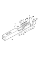
- FIG. 3 is a perspective view showing a configuration of a crimp terminal according to an embodiment of the present invention.
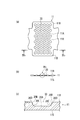
- 4A and 4B are diagrams showing a state before crimping of the conductor crimping portion of the crimping terminal of FIG. 3, wherein FIG. 4A is a developed plan view, FIG.
- FIG. 4B is a sectional view taken along the arrow IVb-IVb in FIG.
- FIG. 4 is an enlarged view of the IVc portion of (b).
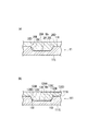
- 5A and 5B are views showing the state of the conductor after crimping into the concave serration.
- FIG. 5A is an enlarged cross-sectional view showing the state of the conductor entering the serration (small circular recess) in FIG.
- These are expanded sectional views which show the mode of a conductor entering with respect to the serration of the related crimp terminal as a comparative example.
- FIG. 3 is a perspective view showing the configuration of the crimp terminal according to the embodiment
- FIG. 4 is a diagram showing a state before crimping of the conductor crimp part of the crimp terminal
- FIG. 4A is a developed plan view
- FIG. ) Is a cross-sectional view taken along the line IVb-IVb in FIG. 4A
- FIG. 4C is an enlarged view of a portion IVc in FIG. 4B.
- the crimp terminal 1 is of a female type, and a male terminal on the mating connector side is disposed at the front of the terminal in the longitudinal direction (the longitudinal direction of the conductor of the electric wire to be connected, that is, the direction in which the electric wire extends).
- a coating caulking portion 12 that is caulked to a portion of the electric wire with an insulating coating.
- connection part 14 Between the electrical connection part 10 and the conductor crimping
- the conductor crimping portion 11 includes a bottom plate 11A and a pair of conductor crimping pieces 11B and 11B that are extended from the left and right side edges of the bottom plate 11A and are crimped so as to wrap the conductors of the electric wires disposed on the inner surface of the bottom plate 11A.
- the cover crimping portion 12 is a pair of crimps so as to wrap the bottom plate 12A and electric wires (parts with an insulation coating) that extend upward from the left and right side edges of the bottom plate 12A and are arranged on the inner surface of the bottom plate 12A.
- the covering crimping pieces 12B and 12B are formed in a substantially U-shaped cross section.
- the first connecting portion 13 and the second connecting portion 14 before and after the conductor crimping portion 11 are both bottom plates 13A and 14A, and low-profile side plates 13B and 14B that stand upward from the left and right edges of the bottom plates 13A and 14A. And a U-shaped cross section.
- the bottom plate (the bottom plate 13A of the first connecting portion 13, the bottom plate 11A of the conductor crimping portion 11, the second connecting portion) in the range from the bottom plate (not shown) of the front electrical connecting portion 10 to the last cover crimping portion 12.
- the bottom plate 14A of the portion 14 and the bottom plate 12A of the cover crimping portion 12 are continuously formed in a single strip shape.
- the front and rear ends of the low-profile side plate 13B of the first connecting portion 13 are respectively connected to the lower half of the rear end of the side plate (reference numeral omitted) of the electrical connecting portion 10 and the front end of the conductor crimping piece 11B of the conductor crimping portion 11.
- the front and rear ends of the low-side side plate 14B of the second connecting portion 14 are respectively below the rear end of the conductor crimping piece 11B of the conductor crimping portion 11 and the front end of the covering crimping piece 12B of the covering crimping portion 12. Each half is continuous.
- the inner surface 11R on the side in contact with the conductor of the electric wire among the inner surface 11R and the outer surface 11S of the conductor crimping portion 11 has a large number of small serrations as concave serrations.
- the circular recesses 20 are provided so as to be scattered in a staggered manner in a state of being separated from each other.
- each small circular recess 20 is rectangular or inverted trapezoidal, and the inner bottom surface 20 ⁇ / b> A of the recess 20 It is formed substantially parallel to the outer surface 11S.
- a rounded portion 20C that connects the inner bottom surface 20A and the inner peripheral side surface 20B with a smooth continuous curved surface is provided.
- the serration of the conductor crimping portion 11 can be manufactured by pressing with a mold having a large number of cylindrical convex portions corresponding to the concave portions 20, and the round portion at the inner peripheral corner of the concave portion 20 of the serrations.
- 20C can be processed by attaching a rounded portion to the periphery of the tip of the cylindrical convex portion of the mold.
- a case of making by electric discharge machining can be considered.
- an electrode first, a circular concave portion for making a cylindrical convex portion of a mold is processed by a drill. And the press metal mold
- a rounded portion is naturally generated at the peripheral edge of the tip of the convex portion of the mold. Therefore, by transferring the rounded portion to the terminal material with a press, the rounded portion 20C can be processed at the inner peripheral corner portion of the concave portion 20 of the serration of the terminal.
- the crimp terminal 1 In order to crimp the conductor crimping portion 11 of the crimp terminal 1 to the conductor at the end of the electric wire, the crimp terminal 1 is placed on the mounting surface (upper surface) of the lower mold (anvil) (not shown), and the conductor at the end of the electric wire is attached. It is inserted between the conductor crimping pieces 11A of the conductor crimping part 11 and placed on the upper surface of the bottom plate 11A. Then, by lowering the upper mold (crimper) relative to the lower mold, the tip side of the conductor crimping piece 11B is gradually tilted inward on the upper mold guide slope.
- the tip of the conductor crimping piece 11B is formed with a curved surface that continues from the guide slope of the upper mold to the central chevron.
- the conductor crimping piece 11B is crimped so as to enclose the conductor by rolling it back to the conductor side and biting into the conductor while rubbing the tips of the conductor crimping pieces 11B.
- the conductor crimping portion 11 of the crimp terminal 1 can be connected to the conductor of the electric wire by crimping.
- the covering crimping portion 12 is gradually bent inward using the lower mold and the upper mold, and the covering crimping piece 12B is crimped to the portion of the electric wire with the insulation coating. By doing so, the crimp terminal 1 can be electrically and mechanically connected to the electric wire.
- the conductor of the electric wire enters the small circular recess 20 as a serration on the inner surface of the conductor crimping portion 11 while being plastically deformed by the pressing force, thereby the terminal 1 and the electric wire.
- the bonding of is strengthened.
- the inner peripheral corner portion where the inner bottom surface 20A and the inner peripheral side surface 20B of the small circular recess 20 intersect is constituted by a smooth curved rounded portion 20C, the conductor Wa entering the recess 20 is It will flow smoothly along the rounded portion 20C, and the gap generated at the inner peripheral corner can be reduced. Therefore, when the gap is large, the oxide film grows from the gap due to the effects of thermal shock, mechanical vibration, etc., and the contact conductivity between the conductor and the terminal may decrease. By reducing the gap, the growth of the oxide film can be suppressed, and good contact conduction performance can be maintained for a long time.
- the crimp terminal 1 is a female terminal fitting having a box-shaped electrical connection portion 10, but is not limited thereto, and may be a male terminal fitting having a male tab, or a metal plate material having a through hole.
- a so-called LA terminal may be formed, and a crimp terminal having an arbitrary shape may be used as necessary.
Landscapes
- Connections Effected By Soldering, Adhesion, Or Permanent Deformation (AREA)
Abstract
導体圧着部(11)のセレーションとして、導体圧着部(11)が電線の導体(Wa)に圧着される前の状態において、導体圧着部(11)の内面(11R)に、複数の円形の凹部(20)が互いに離間した状態で点在するように設けられている。各凹部(20)の内底面(20A)と内周側面(20B)との交わる内周隅部に、内底面(20A)と内周側面(20B)とを滑らかな連続した曲面で繋ぐアール部(20C)が設けられている。
Description
本発明は、例えば、自動車の電装系に使用される断面U字状の導体圧着部を有したオープンバレルタイプの圧着端子に関する。
図1は、例えば、特許文献1に記載された関連する圧着端子の構成を示す斜視図である。
圧着端子101は、端子の長手方向(接続する電線の導体の長手方向でもある)の前部に、相手コネクタ側の端子に接続される電気接続部110を備え、その後部に、電線(図示略)の端末の露出した導体に加締められる導体圧着部111を備え、さらにその後部に、電線の絶縁被覆の付いた部分に加締められる被覆加締部112を備えている。電気接続部110と導体圧着部111の間に、それらの間を繋ぐ第1の繋ぎ部113を備えている。導体圧着部111と被覆加締部112の間に、それらの間を繋ぐ第2の繋ぎ部114を備えている。
導体圧着部111は、底板111Aと、底板111Aの左右両側縁から上方に延設されて底板111Aの内面上に配された電線の導体を包むように加締められる一対の導体加締片111B、111Bとで断面略U字状に形成されている。被覆加締部112は、底板112Aと、底板112Aの左右両側縁から上方に延設されて底板112Aの内面上に配された電線(絶縁被覆の付いた部分)を包むように加締められる一対の被覆加締片112B、112Bと、で断面略U字状に形成されている。
導体圧着部111の前後の第1の繋ぎ部113および第2の繋ぎ部114は、共に、底板113A、114Aと、底板113A、114Aの左右両側縁から上方に起立した低背の側板113B、114Bとで断面U字状に形成されている。
そして、前部の電気接続部110の底板(図示略)から最後部の被覆加締部112までの範囲の底板(第1の繋ぎ部113の底板113A、導体圧着部111の底板111A、第2の繋ぎ部114の底板114A、被覆加締部112の底板112A)が、1枚の帯板状に連続して形成されている。また、第1の繋ぎ部113の低背の側板113Bの前後端は、電気接続部110の側板(符号省略)の後端および導体圧着部111の導体加締片111Bの前端の各下半部にそれぞれ連続し、第2の繋ぎ部114の低背の側板114Bの前後端は、導体圧着部111の導体加締片111Bの後端および被覆加締部112の被覆加締片112Bの前端の各下半部にそれぞれ連続している。
導体圧着部111の内面111R及び外面111Sのうち、電線の導体に接する側の内面111Rには、電線の導体の延びる方向(端子長手方向)と直交する方向に延びる複数本の凹溝状のセレーション120が設けられている。
図2は導体圧着部111の内面に形成されたセレーション120の詳細図であり、図2(a)は導体圧着部111を展開して示す平面図、図2(b)は図2(a)のIIb-IIb矢視断面図、図2(c)は図2(b)のIIc部の拡大図である。
凹溝状のセレーション120の断面形状は矩形状か逆台形状になっており、内底面120Aは、導体圧着部111の外面111Sとほぼ平行に形成されている。内側面120Bと内底面120Aの交わる内隅部120Cは、平面と平面が交わる角張った部分として形成され、内側面120Bと導体圧着部111の内面111Rの交わる孔縁120Dは角張ったエッジとして形成されている。
この圧着端子101の導体圧着部111を電線の端末の導体に圧着するには、図示しない下型(アンビル)の載置面(上面)上に圧着端子101を載せると共に、電線の端末の導体を導体圧着部111の導体加締片111A間に挿入し、底板111Aの上面に載せる。そして、上型(クリンパ)を下型に対して相対的に下降させることにより、上型の案内斜面で導体加締片111Bの先端側を徐々に内側に倒して行く。
そして、さらに上型(クリンパ)を下型に対して相対的に下降させることにより、最終的に、上型の案内斜面から中央の山形部に連なる湾曲面で、導体加締片111Bの先端を導体側に折り返すように丸めて、導体加締片111Bの先端同士を擦り合わせながら導体に食い込ませることにより、導体を包むように導体加締片111Bを加締める。
以上の操作により、圧着端子101の導体圧着部111を電線の導体に圧着によって接続することができる。なお、被覆加締部112についても同様に、下型と上型を用いて被覆加締片112Bを内側に徐々に曲げて行き、被覆加締片112Bを電線の絶縁被覆の付いた部分に加締める。こうすることにより、圧着端子101を電線に電気的および機械的に接続することができる。
このような加締めによる圧着を行った際、加圧力により電線の導体は、導体圧着部111の内面のセレーション120の中に塑性変形しながら入り込み、それにより端子101と電線の接合が強化される。
ところで、上述した関連する圧着端子101では、導体圧着部111の内面111Rに、電線の延びる方向に直交する凹溝状のセレーション120が設けられていたが、必ずしも十分な接触導通性が得られないことがあった。すなわち、導体圧着部111を電線の導体に圧着させた際には、押圧力により流動する導体の表面とセレーションの孔縁とが擦れ合ったり、セレーションの中に入り込む導体の表面とセレーションの内側面が擦れ合ったりすることで、導体の表面の酸化皮膜が剥ぎ取られて、露出した新生面が端子と接触導通する。この点、関連するセレーション120は直線状のものであるため、電線の導体が端子の長手方向に流動する場合には有効性を発揮するものの、それ以外の方向への導体の伸びに対してはあまり有効性を発揮することができなかった。また、図5(b)に示すように、セレーション120の内底面120Aと内側面120Bとの交わる内隅部120Cが角張っているので、セレーション120の中に入り込んだ導体Waがその内隅部120Cにまで十分に行き渡らず、内隅部120Cに隙間150が生じやすかった。そのため、隙間150が大きく生じている場合には、熱衝撃や機械的な振動等の影響で、その隙間150が起点となって酸化皮膜が成長し、導体Waと端子101の接触導通性が低下するおそれがあった。
本発明は、導体と端子の接触導通性を常に高く維持することができる圧着端子を提供することを目的とする。
本発明のアスペクトは、端子長手方向の前部に設けられた電気接続部と、前記電気接続部の後部に設けられ、電線の端末の導体に圧着して接続される導体圧着部であって、底板と前記底板の左右両側縁から上方に延設されて前記底板の内面上に配された前記導体を包むように加締められる一対の導体加締片とで断面U字状に形成された導体圧着部と、を備え、前記導体圧着部は、前記電線の端末の導体に圧着される前の状態において、前記導体圧着部の内面に、互いに離間した状態で点在する複数の円形の凹部をセレーションとして有し、前記各凹部は、その内底面と内周側面との交わる内周隅部に、前記内底面と前記内周側面とを滑らかな連続した曲面で繋ぐアール部を有する圧着端子であることを要旨とする。
前記アスペクトによれば、次の効果を得ることができる。すなわち、この圧着端子を使用して導体圧着部を電線の導体に圧着させた場合、導体圧着部の内面にセレーションとして設けられた小円形の各凹部の中に電線の導体が塑性変形しながら入り込むことで、端子と導体の接合が強化される。その際、押圧力により流動する導体の表面と各凹部の孔縁とが擦れ合ったり、凹部の中に入り込む導体の表面と凹部の内側面が擦れ合ったりすることで、導体の表面の酸化皮膜が剥ぎ取られて、露出した新生面が端子と接触導通する。その点、この圧着端子では、多数の小円形の凹部がセレーションとして設けられているので、導体の伸び方向に拘わらず、凹部の孔縁のトータル長が酸化皮膜を削り取る上で有効性を発揮する。従って、関連する例のように電線の導体の延びる方向に交差する直線状のセレーションが設けられている場合よりも、新生面の露出による接触導通効果を高めることができる。小円形の凹部の内底面と内周側面との交わる内周隅部は、滑らかな曲面状のアール部により構成されているので、凹部の中に入り込んだ導体が、そのアール部に沿ってスムーズに流動することになり、内周隅部に生じる隙間を減少させることができる。そのため、隙間が大きい場合には、熱衝撃や機械的な振動等の影響で、その隙間が起点となって酸化皮膜が成長し、導体と端子の接触導通性が低下するおそれがあったが、隙間の減少が図れることにより、酸化皮膜の成長を抑制することができて、良好な接触導通性能を長期間維持することができる。
以下、本発明の一実施形態を図面を参照して説明する。
図3は実施形態に係る圧着端子の構成を示す斜視図、図4は同圧着端子の導体圧着部の圧着前の状態を示す図で、図4(a)は展開平面図、図4(b)は図4(a)のIVb-IVb矢視断面図、図4(c)は図4(b)のIVc部の拡大図である。
図3に示すように、圧着端子1は、雌型のもので、端子の長手方向(接続する電線の導体の長手方向つまり電線の延びる方向でもある)の前部に、相手コネクタ側の雄端子に接続されるボックス型の電気接続部10を備え、その後部に、電線(図示略)の端末の露出した導体Wa(図4参照)に加締められる導体圧着部11を備え、さらにその後部に、電線の絶縁被覆の付いた部分に加締められる被覆加締部12を備えている。電気接続部10と導体圧着部11の間に、それらの間を繋ぐ第1の繋ぎ部13を備えている。導体圧着部11と被覆加締部12の間に、それらの間を繋ぐ第2の繋ぎ部14を備えている。
導体圧着部11は、底板11Aと、底板11Aの左右両側縁から上方に延設されて底板11Aの内面上に配された電線の導体を包むように加締められる一対の導体加締片11B、11Bとで断面略U字状に形成されている。被覆加締部12は、底板12Aと、底板12Aの左右両側縁から上方に延設されて底板12Aの内面上に配された電線(絶縁被覆の付いた部分)を包むように加締められる一対の被覆加締片12B、12Bとで断面略U字状に形成されている。
導体圧着部11の前後の第1の繋ぎ部13および第2の繋ぎ部14は、共に、底板13A、14Aと、底板13A、14Aの左右両側縁から上方に起立した低背の側板13B、14Bとで断面U字状に形成されている。
前部の電気接続部10の底板(図示略)から最後部の被覆加締部12までの範囲の底板(第1の繋ぎ部13の底板13A、導体圧着部11の底板11A、第2の繋ぎ部14の底板14A、被覆加締部12の底板12A)が、1枚の帯板状に連続して形成されている。第1の繋ぎ部13の低背の側板13Bの前後端は、電気接続部10の側板(符号省略)の後端および導体圧着部11の導体加締片11Bの前端の各下半部にそれぞれ連続し、第2の繋ぎ部14の低背の側板14Bの前後端は、導体圧着部11の導体加締片11Bの後端および被覆加締部12の被覆加締片12Bの前端の各下半部にそれぞれ連続している。
導体圧着部11が電線の導体に圧着される前の状態において、導体圧着部11の内面11R及び外面11Sのうち、電線の導体に接する側の内面11Rには、凹状のセレーションとして、多数の小円形の凹部20が互いに離間した状態で、千鳥状に点在するように設けられている。
図4(b)及び図4(c)に示すように、各小円形の凹部20の断面形状は矩形状か逆台形状になっており、凹部20の内底面20Aは、導体圧着部11の外面11Sとほぼ平行に形成されている。凹部20の内側面20Bと内底面20Aの交わる内周隅部には、内底面20Aと内周側面20Bとを滑らかな連続した曲面で繋ぐアール部20Cが設けられている。
この導体圧着部11のセレーションは、凹部20に対応した多数の円柱状の凸部を有した金型でプレス加工することにより製作することができ、セレーションの凹部20の内周隅部のアール部20Cは、金型の円柱状の凸部の先端周縁にアール部を付けておくことで加工することができる。
プレス金型の作り方の第1の方法としては、放電加工で作る場合が考えられる。その場合は、電極として、まず、金型の円柱状の凸部を作るための円形の凹部をドリルで加工する。そして、ドリル加工した凹部を多数持つ電極を用いて放電加工により、円柱状の凸部を有するプレス金型を作る。その際、放電加工の特性により、金型の凸部の先端周縁には自然にアール部が生成される。従って、そのアール部をプレスで端子材料に転写することにより、端子のセレーションの凹部20の内周隅部にアール部20Cを加工することができる。
第2の方法として、ブロックに円柱状のピンを多数嵌め込んで凸部を形成する場合が考えられる。その場合は、まず、ブロックにドリルで孔を開け、各孔にピンの下半部を埋め込む。すると、各ピンの上半部が突出することで、多数の凸部を有した金型ができる。その際、各ピンの先端周縁にアール部を付けておく。従って、そのアール部をプレスで端子材料に転写することにより、端子のセレーションの凹部20の内周隅部にアール部20Cを加工することができる。
この圧着端子1の導体圧着部11を電線の端末の導体に圧着するには、図示しない下型(アンビル)の載置面(上面)上に圧着端子1を載せると共に、電線の端末の導体を導体圧着部11の導体加締片11A間に挿入し、底板11Aの上面に載せる。そして、上型(クリンパ)を下型に対して相対的に下降させることにより、上型の案内斜面で導体加締片11Bの先端側を徐々に内側に倒して行く。
そして、さらに上型(クリンパ)を下型に対して相対的に下降させることにより、最終的に、上型の案内斜面から中央の山形部に連なる湾曲面で、導体加締片11Bの先端を導体側に折り返すように丸めて、導体加締片11Bの先端同士を擦り合わせながら導体に食い込ませることにより、導体を包むように導体加締片11Bを加締める。
以上の操作により、圧着端子1の導体圧着部11を電線の導体に圧着によって接続することができる。被覆加締部12についても同様に、下型と上型を用いて被覆加締片12Bを内側に徐々に曲げて行き、被覆加締片12Bを電線の絶縁被覆の付いた部分に加締める。こうすることにより、圧着端子1を電線に電気的および機械的に接続することができる。
このような加締めによる圧着を行った際、加圧力により電線の導体は、導体圧着部11の内面のセレーションとしての小円形の凹部20の中に塑性変形しながら入り込み、それにより端子1と電線の接合が強化される。
その際、図5(a)に示すように、押圧力により流動する導体Waの表面と各凹部20の孔縁20Dとが擦れ合ったり、凹部20の中に入り込む導体Waの表面と凹部20の内側面20Bが擦れ合ったりすることで、導体Waの表面の酸化皮膜が剥ぎ取られて、露出した新生面が端子と接触導通する。
その点、この圧着端子1では、多数の小円形の凹部20がセレーションとして設けられているので、導体Waの伸び方向に拘わらず、凹部20の孔縁20Dのトータル長が酸化皮膜を削り取る上で有効性を発揮する。従って、図5(b)の関連する例のように電線の導体Waの延びる方向に交差する直線状のセレーション120が設けられている場合よりも、新生面の露出による接触導通効果を高めることができる。
小円形の凹部20の内底面20Aと内周側面20Bとの交わる内周隅部は、滑らかな曲面状のアール部20Cにより構成されているので、凹部20の中に入り込んだ導体Waが、そのアール部20Cに沿ってスムーズに流動することになり、内周隅部に生じる隙間を減少させることができる。そのため、隙間が大きい場合には、熱衝撃や機械的な振動等の影響で、その隙間が起点となって酸化皮膜が成長し、導体と端子の接触導通性が低下するおそれがあったが、隙間の減少が図れることにより、酸化皮膜の成長を抑制することができて、良好な接触導通性能を長期間維持することができる。
上記実施形態においては、圧着端子1はボックス型の電気接続部10を有する雌端子金具としたが、これに限られず、雄タブを有する雄端子金具としてもよいし、また金属板材に貫通孔が形成されたいわゆるLA端子としてもよく、必要に応じて任意の形状の圧着端子とすることができる。
以上、本発明の実施形態について説明したが、本発明は上記実施形態には限定されず、種々の変形が可能である。
Claims (1)
- 端子長手方向の前部に設けられた電気接続部と、
前記電気接続部の後部に設けられ、電線の端末の導体に圧着して接続される導体圧着部であって、底板と前記底板の左右両側縁から上方に延設されて前記底板の内面上に配された前記導体を包むように加締められる一対の導体加締片とで断面U字状に形成された導体圧着部と、を備え、
前記導体圧着部は、前記電線の端末の導体に圧着される前の状態において、前記導体圧着部の内面に、互いに離間した状態で点在する複数の円形の凹部をセレーションとして有し、
前記各凹部は、その内底面と内周側面との交わる内周隅部に、前記内底面と前記内周側面とを滑らかな連続した曲面で繋ぐアール部を有する
圧着端子。
Priority Applications (3)
| Application Number | Priority Date | Filing Date | Title |
|---|---|---|---|
| EP11814434.4A EP2602874B1 (en) | 2010-08-05 | 2011-07-15 | Crimped terminal |
| US13/813,488 US8870612B2 (en) | 2010-08-05 | 2011-07-15 | Crimped terminal |
| CN201180038587.XA CN103069652B (zh) | 2010-08-05 | 2011-07-15 | 压接端子 |
Applications Claiming Priority (2)
| Application Number | Priority Date | Filing Date | Title |
|---|---|---|---|
| JP2010176039A JP5601925B2 (ja) | 2010-08-05 | 2010-08-05 | 圧着端子 |
| JP2010-176039 | 2010-08-05 |
Publications (1)
| Publication Number | Publication Date |
|---|---|
| WO2012017804A1 true WO2012017804A1 (ja) | 2012-02-09 |
Family
ID=45559311
Family Applications (1)
| Application Number | Title | Priority Date | Filing Date |
|---|---|---|---|
| PCT/JP2011/066189 Ceased WO2012017804A1 (ja) | 2010-08-05 | 2011-07-15 | 圧着端子 |
Country Status (5)
| Country | Link |
|---|---|
| US (1) | US8870612B2 (ja) |
| EP (1) | EP2602874B1 (ja) |
| JP (1) | JP5601925B2 (ja) |
| CN (1) | CN103069652B (ja) |
| WO (1) | WO2012017804A1 (ja) |
Families Citing this family (2)
| Publication number | Priority date | Publication date | Assignee | Title |
|---|---|---|---|---|
| JP5634789B2 (ja) * | 2010-08-05 | 2014-12-03 | 矢崎総業株式会社 | 圧着端子 |
| JP5909345B2 (ja) * | 2011-11-11 | 2016-04-26 | 矢崎総業株式会社 | コネクタ端子 |
Citations (4)
| Publication number | Priority date | Publication date | Assignee | Title |
|---|---|---|---|---|
| JPH05152011A (ja) * | 1991-11-26 | 1993-06-18 | Sumitomo Wiring Syst Ltd | 圧着端子 |
| JP2008305571A (ja) * | 2007-06-05 | 2008-12-18 | Norio Kato | 圧着端子および圧着端子の製造方法 |
| JP2009245695A (ja) | 2008-03-31 | 2009-10-22 | Furukawa Electric Co Ltd:The | 圧着端子 |
| JP2010027463A (ja) * | 2008-07-22 | 2010-02-04 | Sumitomo Wiring Syst Ltd | 端子金具および端子金具付き電線 |
Family Cites Families (6)
| Publication number | Priority date | Publication date | Assignee | Title |
|---|---|---|---|---|
| JPS6018104B2 (ja) * | 1979-01-17 | 1985-05-08 | 住友電気工業株式会社 | アルミニウム導体用圧着端子 |
| JP3576488B2 (ja) * | 2000-12-18 | 2004-10-13 | 日本圧着端子製造株式会社 | 雌端子 |
| CN2495029Y (zh) * | 2001-09-21 | 2002-06-12 | 陈国雄 | 输配电线用的压接套管 |
| JP2010027464A (ja) * | 2008-07-22 | 2010-02-04 | Sumitomo Wiring Syst Ltd | 端子金具及び端子金具付き電線 |
| US20100087104A1 (en) | 2008-10-02 | 2010-04-08 | Gump Bruce S | Terminal crimp having knurl with omega-shaped cross-section |
| JP5634789B2 (ja) * | 2010-08-05 | 2014-12-03 | 矢崎総業株式会社 | 圧着端子 |
-
2010
- 2010-08-05 JP JP2010176039A patent/JP5601925B2/ja active Active
-
2011
- 2011-07-15 WO PCT/JP2011/066189 patent/WO2012017804A1/ja not_active Ceased
- 2011-07-15 US US13/813,488 patent/US8870612B2/en active Active
- 2011-07-15 CN CN201180038587.XA patent/CN103069652B/zh active Active
- 2011-07-15 EP EP11814434.4A patent/EP2602874B1/en not_active Not-in-force
Patent Citations (4)
| Publication number | Priority date | Publication date | Assignee | Title |
|---|---|---|---|---|
| JPH05152011A (ja) * | 1991-11-26 | 1993-06-18 | Sumitomo Wiring Syst Ltd | 圧着端子 |
| JP2008305571A (ja) * | 2007-06-05 | 2008-12-18 | Norio Kato | 圧着端子および圧着端子の製造方法 |
| JP2009245695A (ja) | 2008-03-31 | 2009-10-22 | Furukawa Electric Co Ltd:The | 圧着端子 |
| JP2010027463A (ja) * | 2008-07-22 | 2010-02-04 | Sumitomo Wiring Syst Ltd | 端子金具および端子金具付き電線 |
Non-Patent Citations (1)
| Title |
|---|
| See also references of EP2602874A4 |
Also Published As
| Publication number | Publication date |
|---|---|
| EP2602874A4 (en) | 2014-03-12 |
| EP2602874B1 (en) | 2015-12-09 |
| JP5601925B2 (ja) | 2014-10-08 |
| US8870612B2 (en) | 2014-10-28 |
| EP2602874A1 (en) | 2013-06-12 |
| US20130130564A1 (en) | 2013-05-23 |
| CN103069652B (zh) | 2015-05-20 |
| JP2012038488A (ja) | 2012-02-23 |
| CN103069652A (zh) | 2013-04-24 |
Similar Documents
| Publication | Publication Date | Title |
|---|---|---|
| JP5601926B2 (ja) | 圧着端子 | |
| JP4996553B2 (ja) | 端子金具及び端子付き電線 | |
| JP5634788B2 (ja) | 圧着端子 | |
| JP2010040404A (ja) | 端子金具及びワイヤーハーネス | |
| WO2011052549A1 (ja) | 圧着端子 | |
| JP2010003467A (ja) | 端子金具及び端子付き電線 | |
| CN101946368A (zh) | 端子连接器和束线 | |
| WO2012018050A1 (ja) | 圧着端子 | |
| JP5886517B2 (ja) | 圧着端子 | |
| JP5634789B2 (ja) | 圧着端子 | |
| JP5601925B2 (ja) | 圧着端子 | |
| JP2010010000A (ja) | 端子金具及び端子付き電線 | |
| JP2010010001A (ja) | 端子金具及び端子付き電線 | |
| JP2010009789A (ja) | 端子金具及び端子付き電線 | |
| JP5650381B2 (ja) | 圧着端子 | |
| JP5316914B2 (ja) | 端子金具及び端子付き電線 | |
| JP2011243519A (ja) | 圧着端子および圧着端子付き平形ケーブル | |
| JP5249838B2 (ja) | 圧着端子 | |
| JP6933536B2 (ja) | 電線付端子 | |
| JP2011103264A (ja) | 圧着端子の圧着構造 | |
| JP2016213134A (ja) | コネクタ | |
| JP2009152055A (ja) | 圧着端子、および、圧着端子のアルミニウム電線に対する圧着構造 |
Legal Events
| Date | Code | Title | Description |
|---|---|---|---|
| WWE | Wipo information: entry into national phase |
Ref document number: 201180038587.X Country of ref document: CN |
|
| 121 | Ep: the epo has been informed by wipo that ep was designated in this application |
Ref document number: 11814434 Country of ref document: EP Kind code of ref document: A1 |
|
| WWE | Wipo information: entry into national phase |
Ref document number: 13813488 Country of ref document: US |
|
| WWE | Wipo information: entry into national phase |
Ref document number: 2011814434 Country of ref document: EP |
|
| NENP | Non-entry into the national phase |
Ref country code: DE |