WO2012017804A1 - Borne sertie - Google Patents
Borne sertie Download PDFInfo
- Publication number
- WO2012017804A1 WO2012017804A1 PCT/JP2011/066189 JP2011066189W WO2012017804A1 WO 2012017804 A1 WO2012017804 A1 WO 2012017804A1 JP 2011066189 W JP2011066189 W JP 2011066189W WO 2012017804 A1 WO2012017804 A1 WO 2012017804A1
- Authority
- WO
- WIPO (PCT)
- Prior art keywords
- conductor
- terminal
- crimping
- bottom plate
- conductor crimping
- Prior art date
- Legal status (The legal status is an assumption and is not a legal conclusion. Google has not performed a legal analysis and makes no representation as to the accuracy of the status listed.)
- Ceased
Links
Images


Classifications
-
- H—ELECTRICITY
- H01—ELECTRIC ELEMENTS
- H01R—ELECTRICALLY-CONDUCTIVE CONNECTIONS; STRUCTURAL ASSOCIATIONS OF A PLURALITY OF MUTUALLY-INSULATED ELECTRICAL CONNECTING ELEMENTS; COUPLING DEVICES; CURRENT COLLECTORS
- H01R4/00—Electrically-conductive connections between two or more conductive members in direct contact, i.e. touching one another; Means for effecting or maintaining such contact; Electrically-conductive connections having two or more spaced connecting locations for conductors and using contact members penetrating insulation
- H01R4/10—Electrically-conductive connections between two or more conductive members in direct contact, i.e. touching one another; Means for effecting or maintaining such contact; Electrically-conductive connections having two or more spaced connecting locations for conductors and using contact members penetrating insulation effected solely by twisting, wrapping, bending, crimping, or other permanent deformation
- H01R4/18—Electrically-conductive connections between two or more conductive members in direct contact, i.e. touching one another; Means for effecting or maintaining such contact; Electrically-conductive connections having two or more spaced connecting locations for conductors and using contact members penetrating insulation effected solely by twisting, wrapping, bending, crimping, or other permanent deformation by crimping
- H01R4/188—Electrically-conductive connections between two or more conductive members in direct contact, i.e. touching one another; Means for effecting or maintaining such contact; Electrically-conductive connections having two or more spaced connecting locations for conductors and using contact members penetrating insulation effected solely by twisting, wrapping, bending, crimping, or other permanent deformation by crimping having an uneven wire-receiving surface to improve the contact
-
- H—ELECTRICITY
- H01—ELECTRIC ELEMENTS
- H01R—ELECTRICALLY-CONDUCTIVE CONNECTIONS; STRUCTURAL ASSOCIATIONS OF A PLURALITY OF MUTUALLY-INSULATED ELECTRICAL CONNECTING ELEMENTS; COUPLING DEVICES; CURRENT COLLECTORS
- H01R4/00—Electrically-conductive connections between two or more conductive members in direct contact, i.e. touching one another; Means for effecting or maintaining such contact; Electrically-conductive connections having two or more spaced connecting locations for conductors and using contact members penetrating insulation
- H01R4/28—Clamped connections, spring connections
-
- H—ELECTRICITY
- H01—ELECTRIC ELEMENTS
- H01R—ELECTRICALLY-CONDUCTIVE CONNECTIONS; STRUCTURAL ASSOCIATIONS OF A PLURALITY OF MUTUALLY-INSULATED ELECTRICAL CONNECTING ELEMENTS; COUPLING DEVICES; CURRENT COLLECTORS
- H01R4/00—Electrically-conductive connections between two or more conductive members in direct contact, i.e. touching one another; Means for effecting or maintaining such contact; Electrically-conductive connections having two or more spaced connecting locations for conductors and using contact members penetrating insulation
- H01R4/10—Electrically-conductive connections between two or more conductive members in direct contact, i.e. touching one another; Means for effecting or maintaining such contact; Electrically-conductive connections having two or more spaced connecting locations for conductors and using contact members penetrating insulation effected solely by twisting, wrapping, bending, crimping, or other permanent deformation
- H01R4/18—Electrically-conductive connections between two or more conductive members in direct contact, i.e. touching one another; Means for effecting or maintaining such contact; Electrically-conductive connections having two or more spaced connecting locations for conductors and using contact members penetrating insulation effected solely by twisting, wrapping, bending, crimping, or other permanent deformation by crimping
- H01R4/183—Electrically-conductive connections between two or more conductive members in direct contact, i.e. touching one another; Means for effecting or maintaining such contact; Electrically-conductive connections having two or more spaced connecting locations for conductors and using contact members penetrating insulation effected solely by twisting, wrapping, bending, crimping, or other permanent deformation by crimping for cylindrical elongated bodies, e.g. cables having circular cross-section
- H01R4/184—Electrically-conductive connections between two or more conductive members in direct contact, i.e. touching one another; Means for effecting or maintaining such contact; Electrically-conductive connections having two or more spaced connecting locations for conductors and using contact members penetrating insulation effected solely by twisting, wrapping, bending, crimping, or other permanent deformation by crimping for cylindrical elongated bodies, e.g. cables having circular cross-section comprising a U-shaped wire-receiving portion
- H01R4/185—Electrically-conductive connections between two or more conductive members in direct contact, i.e. touching one another; Means for effecting or maintaining such contact; Electrically-conductive connections having two or more spaced connecting locations for conductors and using contact members penetrating insulation effected solely by twisting, wrapping, bending, crimping, or other permanent deformation by crimping for cylindrical elongated bodies, e.g. cables having circular cross-section comprising a U-shaped wire-receiving portion combined with a U-shaped insulation-receiving portion
Definitions
- the present invention relates to an open barrel type crimp terminal having a conductor crimping portion having a U-shaped cross section used in, for example, an electrical system of an automobile.
- FIG. 1 is a perspective view showing a configuration of a related crimp terminal described in Patent Document 1, for example.
- the crimp terminal 101 includes an electrical connection portion 110 connected to a terminal on the mating connector side at a front portion in a longitudinal direction of the terminal (which is also a longitudinal direction of a conductor of a wire to be connected), and an electrical wire (not shown) at a rear portion thereof. ) Is provided with a conductor crimping portion 111 that is crimped to the exposed conductor of the terminal, and further, a covering crimping portion 112 that is crimped to a portion of the electric wire with an insulating coating is provided. Between the electrical connection part 110 and the conductor crimping
- the conductor crimping portion 111 includes a bottom plate 111A and a pair of conductor crimping pieces 111B and 111B that are extended upward from the left and right side edges of the bottom plate 111A and are crimped so as to wrap the conductor of the electric wire disposed on the inner surface of the bottom plate 111A.
- the covering caulking portion 112 is a pair of caulking so as to wrap the bottom plate 112A and electric wires (parts with an insulating coating) that extend upward from the left and right side edges of the bottom plate 112A and are arranged on the inner surface of the bottom plate 112A.
- the covering caulking pieces 112B and 112B are formed in a substantially U-shaped cross section.
- the first connecting portion 113 and the second connecting portion 114 before and after the conductor crimping portion 111 are both bottom plates 113A and 114A and low-profile side plates 113B and 114B that stand up from the left and right edges of the bottom plates 113A and 114A. And a U-shaped cross section.
- the bottom plate (the bottom plate 113A of the first connecting portion 113, the bottom plate 111A of the conductor crimping portion 111, the second plate) in the range from the bottom plate (not shown) of the front electrical connecting portion 110 to the last covering crimping portion 112.
- the bottom plate 114A of the connecting portion 114 and the bottom plate 112A of the cover crimping portion 112 are continuously formed in a single strip shape.
- the front and rear ends of the low-profile side plate 113B of the first connecting portion 113 are the lower half portions of the rear end of the side plate (reference number omitted) of the electrical connection portion 110 and the front end of the conductor crimping piece 111B of the conductor crimping portion 111.
- the front and rear ends of the low-side side plate 114B of the second connecting portion 114 are the rear end of the conductor crimping piece 111B of the conductor crimping portion 111 and the front end of the covering crimping piece 112B of the covering crimping portion 112, respectively.
- Each lower half is continuous.
- the inner surface 111R on the side in contact with the conductor of the electric wire has a plurality of groove-shaped serrations extending in a direction orthogonal to the direction in which the conductor of the electric wire extends (terminal longitudinal direction). 120 is provided.
- FIG. 2 is a detailed view of the serration 120 formed on the inner surface of the conductor crimping portion 111.
- FIG. 2 (a) is a plan view showing the conductor crimping portion 111 in an expanded state
- FIG. 2 (b) is FIG. 2 (a).
- FIG. 2 (c) is an enlarged view of the IIc portion of FIG. 2 (b).
- the cross-sectional shape of the groove-shaped serration 120 is rectangular or inverted trapezoidal, and the inner bottom surface 120A is formed substantially parallel to the outer surface 111S of the conductor crimping portion 111.
- the inner corner 120C where the inner side surface 120B and the inner bottom surface 120A intersect is formed as an angular part where the plane and the plane intersect, and the hole edge 120D where the inner side surface 120B and the inner surface 111R of the conductor crimping part 111 intersect is formed as an angular edge. ing.
- the crimp terminal 101 In order to crimp the conductor crimping portion 111 of the crimp terminal 101 to the conductor at the end of the electric wire, the crimp terminal 101 is placed on the mounting surface (upper surface) of the lower mold (anvil) (not shown) and the conductor at the end of the electric wire is attached. It is inserted between the conductor crimping pieces 111A of the conductor crimping part 111 and placed on the upper surface of the bottom plate 111A. Then, by lowering the upper mold (crimper) relative to the lower mold, the leading end side of the conductor crimping piece 111B is gradually tilted inward on the upper mold guide slope.
- the tip of the conductor crimping piece 111B is formed with a curved surface extending from the guide slope of the upper mold to the central chevron.
- the conductor crimping piece 111B is crimped so as to wrap the conductor by rolling it back to the conductor side and biting into the conductor while rubbing the tips of the conductor crimping pieces 111B.
- the conductor crimping portion 111 of the crimp terminal 101 can be connected to the conductor of the electric wire by crimping.
- the covering crimping portion 112 is also bent gradually inward using the lower mold and the upper mold, and the covering crimping piece 112B is applied to the portion of the electric wire with the insulation coating. Tighten. By doing so, the crimp terminal 101 can be electrically and mechanically connected to the electric wire.
- the conductor of the electric wire enters the serration 120 on the inner surface of the conductor crimping portion 111 while being plastically deformed by the applied pressure, thereby strengthening the bonding between the terminal 101 and the electric wire.
- the groove 111 is provided on the inner surface 111R of the conductor crimping portion 111 so as to be orthogonal to the direction in which the electric wire extends, but sufficient contact conductivity is not always obtained.
- the conductor crimping portion 111 is crimped to the conductor of the electric wire, the surface of the conductor that flows due to the pressing force and the edge of the serration rub against each other, or the surface of the conductor that enters the serration and the inner surface of the serration As a result, the oxide film on the surface of the conductor is peeled off, and the exposed new surface is brought into contact with the terminal.
- the related serration 120 is linear, it is effective when the conductor of the wire flows in the longitudinal direction of the terminal, but for the extension of the conductor in other directions It was not very effective.
- the inner corner 120C where the inner bottom surface 120A and the inner side surface 120B of the serration 120 intersect each other is angular, the conductor Wa that has entered the serration 120 has its inner corner 120C.
- the gap 150 was likely to occur in the inner corner 120C. Therefore, when the gap 150 is large, an oxide film grows from the gap 150 due to the influence of thermal shock, mechanical vibration, etc., and the contact conductivity between the conductor Wa and the terminal 101 decreases. There was a risk.
- An object of the present invention is to provide a crimp terminal capable of constantly maintaining high contact conductivity between a conductor and a terminal.
- the aspect of the present invention is an electrical connection part provided at the front part of the terminal longitudinal direction, and a conductor crimping part provided at the rear part of the electrical connection part and connected by crimping to the conductor of the terminal of the electric wire,
- a conductor crimp formed in a U-shaped cross section by a bottom plate and a pair of conductor crimping pieces that extend upward from the left and right side edges of the bottom plate and are crimped to wrap the conductor disposed on the inner surface of the bottom plate
- the conductor crimping portion serrated with a plurality of circular recesses that are scattered in a state of being separated from each other on the inner surface of the conductor crimping portion before being crimped to the conductor of the end of the electric wire.
- Each of the concave portions is a crimp terminal having a rounded portion connecting the inner bottom surface and the inner peripheral side surface with a smooth continuous curved surface at an inner peripheral corner portion where the inner bottom surface and the inner peripheral side surface intersect. This is the gist.
- the following effects can be obtained. That is, when the crimping portion of the conductor is crimped to the conductor of the electric wire using this crimping terminal, the conductor of the electric wire enters into each small circular recess provided as serration on the inner surface of the crimping portion of the conductor while being plastically deformed. Thus, the bonding between the terminal and the conductor is strengthened. At that time, the surface of the conductor flowing due to the pressing force and the hole edge of each recess rub against each other, or the surface of the conductor entering the recess and the inner surface of the recess rub against each other. Is peeled off and the exposed new surface comes into contact with the terminal.
- the total length of the hole edges of the recesses is effective in scraping off the oxide film regardless of the direction of extension of the conductor. . Therefore, the contact conduction effect due to the exposure of the new surface can be enhanced as compared with the case where a linear serration that intersects the extending direction of the conductor of the electric wire is provided as in the related example.
- the inner peripheral corner where the inner bottom surface and the inner peripheral side surface of the small circular recess intersect is formed by a smooth curved rounded portion, so that the conductor that has entered the concave portion is smooth along the rounded portion. Thus, the gap generated at the inner peripheral corner can be reduced.
- the gap when the gap is large, there is a risk that the contact film between the conductor and the terminal may deteriorate due to the influence of thermal shock, mechanical vibration, etc.
- the growth of the oxide film can be suppressed, and good contact conduction performance can be maintained for a long time.
- FIG. 1 is a perspective view showing a configuration of a related crimp terminal.
- 2 is a diagram showing a state before crimping of a conductor crimping portion of the crimping terminal of FIG. 1, (a) is a developed plan view, (b) is a sectional view taken along the arrow IIb-IIb in (a), and (c).
- FIG. 4 is an enlarged view of a portion IIc in (b).
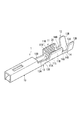
- FIG. 3 is a perspective view showing a configuration of a crimp terminal according to an embodiment of the present invention.
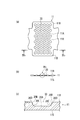
- 4A and 4B are diagrams showing a state before crimping of the conductor crimping portion of the crimping terminal of FIG. 3, wherein FIG. 4A is a developed plan view, FIG.
- FIG. 4B is a sectional view taken along the arrow IVb-IVb in FIG.
- FIG. 4 is an enlarged view of the IVc portion of (b).
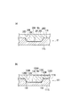
- 5A and 5B are views showing the state of the conductor after crimping into the concave serration.
- FIG. 5A is an enlarged cross-sectional view showing the state of the conductor entering the serration (small circular recess) in FIG.
- These are expanded sectional views which show the mode of a conductor entering with respect to the serration of the related crimp terminal as a comparative example.
- FIG. 3 is a perspective view showing the configuration of the crimp terminal according to the embodiment
- FIG. 4 is a diagram showing a state before crimping of the conductor crimp part of the crimp terminal
- FIG. 4A is a developed plan view
- FIG. ) Is a cross-sectional view taken along the line IVb-IVb in FIG. 4A
- FIG. 4C is an enlarged view of a portion IVc in FIG. 4B.
- the crimp terminal 1 is of a female type, and a male terminal on the mating connector side is disposed at the front of the terminal in the longitudinal direction (the longitudinal direction of the conductor of the electric wire to be connected, that is, the direction in which the electric wire extends).
- a coating caulking portion 12 that is caulked to a portion of the electric wire with an insulating coating.
- connection part 14 Between the electrical connection part 10 and the conductor crimping
- the conductor crimping portion 11 includes a bottom plate 11A and a pair of conductor crimping pieces 11B and 11B that are extended from the left and right side edges of the bottom plate 11A and are crimped so as to wrap the conductors of the electric wires disposed on the inner surface of the bottom plate 11A.
- the cover crimping portion 12 is a pair of crimps so as to wrap the bottom plate 12A and electric wires (parts with an insulation coating) that extend upward from the left and right side edges of the bottom plate 12A and are arranged on the inner surface of the bottom plate 12A.
- the covering crimping pieces 12B and 12B are formed in a substantially U-shaped cross section.
- the first connecting portion 13 and the second connecting portion 14 before and after the conductor crimping portion 11 are both bottom plates 13A and 14A, and low-profile side plates 13B and 14B that stand upward from the left and right edges of the bottom plates 13A and 14A. And a U-shaped cross section.
- the bottom plate (the bottom plate 13A of the first connecting portion 13, the bottom plate 11A of the conductor crimping portion 11, the second connecting portion) in the range from the bottom plate (not shown) of the front electrical connecting portion 10 to the last cover crimping portion 12.
- the bottom plate 14A of the portion 14 and the bottom plate 12A of the cover crimping portion 12 are continuously formed in a single strip shape.
- the front and rear ends of the low-profile side plate 13B of the first connecting portion 13 are respectively connected to the lower half of the rear end of the side plate (reference numeral omitted) of the electrical connecting portion 10 and the front end of the conductor crimping piece 11B of the conductor crimping portion 11.
- the front and rear ends of the low-side side plate 14B of the second connecting portion 14 are respectively below the rear end of the conductor crimping piece 11B of the conductor crimping portion 11 and the front end of the covering crimping piece 12B of the covering crimping portion 12. Each half is continuous.
- the inner surface 11R on the side in contact with the conductor of the electric wire among the inner surface 11R and the outer surface 11S of the conductor crimping portion 11 has a large number of small serrations as concave serrations.
- the circular recesses 20 are provided so as to be scattered in a staggered manner in a state of being separated from each other.
- each small circular recess 20 is rectangular or inverted trapezoidal, and the inner bottom surface 20 ⁇ / b> A of the recess 20 It is formed substantially parallel to the outer surface 11S.
- a rounded portion 20C that connects the inner bottom surface 20A and the inner peripheral side surface 20B with a smooth continuous curved surface is provided.
- the serration of the conductor crimping portion 11 can be manufactured by pressing with a mold having a large number of cylindrical convex portions corresponding to the concave portions 20, and the round portion at the inner peripheral corner of the concave portion 20 of the serrations.
- 20C can be processed by attaching a rounded portion to the periphery of the tip of the cylindrical convex portion of the mold.
- a case of making by electric discharge machining can be considered.
- an electrode first, a circular concave portion for making a cylindrical convex portion of a mold is processed by a drill. And the press metal mold
- a rounded portion is naturally generated at the peripheral edge of the tip of the convex portion of the mold. Therefore, by transferring the rounded portion to the terminal material with a press, the rounded portion 20C can be processed at the inner peripheral corner portion of the concave portion 20 of the serration of the terminal.
- the crimp terminal 1 In order to crimp the conductor crimping portion 11 of the crimp terminal 1 to the conductor at the end of the electric wire, the crimp terminal 1 is placed on the mounting surface (upper surface) of the lower mold (anvil) (not shown), and the conductor at the end of the electric wire is attached. It is inserted between the conductor crimping pieces 11A of the conductor crimping part 11 and placed on the upper surface of the bottom plate 11A. Then, by lowering the upper mold (crimper) relative to the lower mold, the tip side of the conductor crimping piece 11B is gradually tilted inward on the upper mold guide slope.
- the tip of the conductor crimping piece 11B is formed with a curved surface that continues from the guide slope of the upper mold to the central chevron.
- the conductor crimping piece 11B is crimped so as to enclose the conductor by rolling it back to the conductor side and biting into the conductor while rubbing the tips of the conductor crimping pieces 11B.
- the conductor crimping portion 11 of the crimp terminal 1 can be connected to the conductor of the electric wire by crimping.
- the covering crimping portion 12 is gradually bent inward using the lower mold and the upper mold, and the covering crimping piece 12B is crimped to the portion of the electric wire with the insulation coating. By doing so, the crimp terminal 1 can be electrically and mechanically connected to the electric wire.
- the conductor of the electric wire enters the small circular recess 20 as a serration on the inner surface of the conductor crimping portion 11 while being plastically deformed by the pressing force, thereby the terminal 1 and the electric wire.
- the bonding of is strengthened.
- the inner peripheral corner portion where the inner bottom surface 20A and the inner peripheral side surface 20B of the small circular recess 20 intersect is constituted by a smooth curved rounded portion 20C, the conductor Wa entering the recess 20 is It will flow smoothly along the rounded portion 20C, and the gap generated at the inner peripheral corner can be reduced. Therefore, when the gap is large, the oxide film grows from the gap due to the effects of thermal shock, mechanical vibration, etc., and the contact conductivity between the conductor and the terminal may decrease. By reducing the gap, the growth of the oxide film can be suppressed, and good contact conduction performance can be maintained for a long time.
- the crimp terminal 1 is a female terminal fitting having a box-shaped electrical connection portion 10, but is not limited thereto, and may be a male terminal fitting having a male tab, or a metal plate material having a through hole.
- a so-called LA terminal may be formed, and a crimp terminal having an arbitrary shape may be used as necessary.
Landscapes
- Connections Effected By Soldering, Adhesion, Or Permanent Deformation (AREA)
Abstract
Selon la présente invention, une pluralité d'évidements circulaires (20), sous la forme de dentelures sur une partie conductrice sertie (11), est prévue de manière à marquer avec des points, tout en étant espacés les uns des autres, la surface intérieure (11R) de la partie conductrice sertie (11) avant que la partie conductrice sertie (11) ne soit sertie sur un conducteur de câblage électrique (Wa). Une partie courbée (20C), utilisant une surface lisse, continue et courbée de manière à connecter la surface inférieure intérieure (20A) et la surface latérale circonférentielle intérieure (20B) de chaque évidement (20), est prévue sur la partie d'angle joignant la surface inférieure intérieure (20A) et la surface latérale circonférentielle intérieure (20B).
Priority Applications (3)
| Application Number | Priority Date | Filing Date | Title |
|---|---|---|---|
| EP11814434.4A EP2602874B1 (fr) | 2010-08-05 | 2011-07-15 | Borne sertie |
| US13/813,488 US8870612B2 (en) | 2010-08-05 | 2011-07-15 | Crimped terminal |
| CN201180038587.XA CN103069652B (zh) | 2010-08-05 | 2011-07-15 | 压接端子 |
Applications Claiming Priority (2)
| Application Number | Priority Date | Filing Date | Title |
|---|---|---|---|
| JP2010176039A JP5601925B2 (ja) | 2010-08-05 | 2010-08-05 | 圧着端子 |
| JP2010-176039 | 2010-08-05 |
Publications (1)
| Publication Number | Publication Date |
|---|---|
| WO2012017804A1 true WO2012017804A1 (fr) | 2012-02-09 |
Family
ID=45559311
Family Applications (1)
| Application Number | Title | Priority Date | Filing Date |
|---|---|---|---|
| PCT/JP2011/066189 Ceased WO2012017804A1 (fr) | 2010-08-05 | 2011-07-15 | Borne sertie |
Country Status (5)
| Country | Link |
|---|---|
| US (1) | US8870612B2 (fr) |
| EP (1) | EP2602874B1 (fr) |
| JP (1) | JP5601925B2 (fr) |
| CN (1) | CN103069652B (fr) |
| WO (1) | WO2012017804A1 (fr) |
Families Citing this family (2)
| Publication number | Priority date | Publication date | Assignee | Title |
|---|---|---|---|---|
| JP5634789B2 (ja) * | 2010-08-05 | 2014-12-03 | 矢崎総業株式会社 | 圧着端子 |
| JP5909345B2 (ja) * | 2011-11-11 | 2016-04-26 | 矢崎総業株式会社 | コネクタ端子 |
Citations (4)
| Publication number | Priority date | Publication date | Assignee | Title |
|---|---|---|---|---|
| JPH05152011A (ja) * | 1991-11-26 | 1993-06-18 | Sumitomo Wiring Syst Ltd | 圧着端子 |
| JP2008305571A (ja) * | 2007-06-05 | 2008-12-18 | Norio Kato | 圧着端子および圧着端子の製造方法 |
| JP2009245695A (ja) | 2008-03-31 | 2009-10-22 | Furukawa Electric Co Ltd:The | 圧着端子 |
| JP2010027463A (ja) * | 2008-07-22 | 2010-02-04 | Sumitomo Wiring Syst Ltd | 端子金具および端子金具付き電線 |
Family Cites Families (6)
| Publication number | Priority date | Publication date | Assignee | Title |
|---|---|---|---|---|
| JPS6018104B2 (ja) * | 1979-01-17 | 1985-05-08 | 住友電気工業株式会社 | アルミニウム導体用圧着端子 |
| JP3576488B2 (ja) * | 2000-12-18 | 2004-10-13 | 日本圧着端子製造株式会社 | 雌端子 |
| CN2495029Y (zh) * | 2001-09-21 | 2002-06-12 | 陈国雄 | 输配电线用的压接套管 |
| JP2010027464A (ja) * | 2008-07-22 | 2010-02-04 | Sumitomo Wiring Syst Ltd | 端子金具及び端子金具付き電線 |
| US20100087104A1 (en) | 2008-10-02 | 2010-04-08 | Gump Bruce S | Terminal crimp having knurl with omega-shaped cross-section |
| JP5634789B2 (ja) * | 2010-08-05 | 2014-12-03 | 矢崎総業株式会社 | 圧着端子 |
-
2010
- 2010-08-05 JP JP2010176039A patent/JP5601925B2/ja active Active
-
2011
- 2011-07-15 WO PCT/JP2011/066189 patent/WO2012017804A1/fr not_active Ceased
- 2011-07-15 US US13/813,488 patent/US8870612B2/en active Active
- 2011-07-15 CN CN201180038587.XA patent/CN103069652B/zh active Active
- 2011-07-15 EP EP11814434.4A patent/EP2602874B1/fr not_active Not-in-force
Patent Citations (4)
| Publication number | Priority date | Publication date | Assignee | Title |
|---|---|---|---|---|
| JPH05152011A (ja) * | 1991-11-26 | 1993-06-18 | Sumitomo Wiring Syst Ltd | 圧着端子 |
| JP2008305571A (ja) * | 2007-06-05 | 2008-12-18 | Norio Kato | 圧着端子および圧着端子の製造方法 |
| JP2009245695A (ja) | 2008-03-31 | 2009-10-22 | Furukawa Electric Co Ltd:The | 圧着端子 |
| JP2010027463A (ja) * | 2008-07-22 | 2010-02-04 | Sumitomo Wiring Syst Ltd | 端子金具および端子金具付き電線 |
Non-Patent Citations (1)
| Title |
|---|
| See also references of EP2602874A4 |
Also Published As
| Publication number | Publication date |
|---|---|
| EP2602874A4 (fr) | 2014-03-12 |
| EP2602874B1 (fr) | 2015-12-09 |
| JP5601925B2 (ja) | 2014-10-08 |
| US8870612B2 (en) | 2014-10-28 |
| EP2602874A1 (fr) | 2013-06-12 |
| US20130130564A1 (en) | 2013-05-23 |
| CN103069652B (zh) | 2015-05-20 |
| JP2012038488A (ja) | 2012-02-23 |
| CN103069652A (zh) | 2013-04-24 |
Similar Documents
| Publication | Publication Date | Title |
|---|---|---|
| JP5601926B2 (ja) | 圧着端子 | |
| JP4996553B2 (ja) | 端子金具及び端子付き電線 | |
| JP5634788B2 (ja) | 圧着端子 | |
| JP2010040404A (ja) | 端子金具及びワイヤーハーネス | |
| WO2011052549A1 (fr) | Borne de sertissage | |
| JP2010003467A (ja) | 端子金具及び端子付き電線 | |
| CN101946368A (zh) | 端子连接器和束线 | |
| WO2012018050A1 (fr) | Borne à sertir | |
| JP5886517B2 (ja) | 圧着端子 | |
| JP5634789B2 (ja) | 圧着端子 | |
| JP5601925B2 (ja) | 圧着端子 | |
| JP2010010000A (ja) | 端子金具及び端子付き電線 | |
| JP2010010001A (ja) | 端子金具及び端子付き電線 | |
| JP2010009789A (ja) | 端子金具及び端子付き電線 | |
| JP5650381B2 (ja) | 圧着端子 | |
| JP5316914B2 (ja) | 端子金具及び端子付き電線 | |
| JP2011243519A (ja) | 圧着端子および圧着端子付き平形ケーブル | |
| JP5249838B2 (ja) | 圧着端子 | |
| JP6933536B2 (ja) | 電線付端子 | |
| JP2011103264A (ja) | 圧着端子の圧着構造 | |
| JP2016213134A (ja) | コネクタ | |
| JP2009152055A (ja) | 圧着端子、および、圧着端子のアルミニウム電線に対する圧着構造 |
Legal Events
| Date | Code | Title | Description |
|---|---|---|---|
| WWE | Wipo information: entry into national phase |
Ref document number: 201180038587.X Country of ref document: CN |
|
| 121 | Ep: the epo has been informed by wipo that ep was designated in this application |
Ref document number: 11814434 Country of ref document: EP Kind code of ref document: A1 |
|
| WWE | Wipo information: entry into national phase |
Ref document number: 13813488 Country of ref document: US |
|
| WWE | Wipo information: entry into national phase |
Ref document number: 2011814434 Country of ref document: EP |
|
| NENP | Non-entry into the national phase |
Ref country code: DE |