WO2012017918A1 - 電磁式駆動ユニット - Google Patents
電磁式駆動ユニット Download PDFInfo
- Publication number
- WO2012017918A1 WO2012017918A1 PCT/JP2011/067286 JP2011067286W WO2012017918A1 WO 2012017918 A1 WO2012017918 A1 WO 2012017918A1 JP 2011067286 W JP2011067286 W JP 2011067286W WO 2012017918 A1 WO2012017918 A1 WO 2012017918A1
- Authority
- WO
- WIPO (PCT)
- Prior art keywords
- annular
- bobbin
- inner housing
- axial direction
- distance
- Prior art date
- Legal status (The legal status is an assumption and is not a legal conclusion. Google has not performed a legal analysis and makes no representation as to the accuracy of the status listed.)
- Ceased
Links
Images


Classifications
-
- H—ELECTRICITY
- H01—ELECTRIC ELEMENTS
- H01F—MAGNETS; INDUCTANCES; TRANSFORMERS; SELECTION OF MATERIALS FOR THEIR MAGNETIC PROPERTIES
- H01F7/00—Magnets
- H01F7/06—Electromagnets; Actuators including electromagnets
- H01F7/08—Electromagnets; Actuators including electromagnets with armatures
- H01F7/16—Rectilinearly-movable armatures
- H01F7/1607—Armatures entering the winding
-
- F—MECHANICAL ENGINEERING; LIGHTING; HEATING; WEAPONS; BLASTING
- F16—ENGINEERING ELEMENTS AND UNITS; GENERAL MEASURES FOR PRODUCING AND MAINTAINING EFFECTIVE FUNCTIONING OF MACHINES OR INSTALLATIONS; THERMAL INSULATION IN GENERAL
- F16K—VALVES; TAPS; COCKS; ACTUATING-FLOATS; DEVICES FOR VENTING OR AERATING
- F16K31/00—Actuating devices; Operating means; Releasing devices
- F16K31/02—Actuating devices; Operating means; Releasing devices electric; magnetic
- F16K31/06—Actuating devices; Operating means; Releasing devices electric; magnetic using a magnet, e.g. diaphragm valves, cutting off by means of a liquid
-
- H—ELECTRICITY
- H01—ELECTRIC ELEMENTS
- H01F—MAGNETS; INDUCTANCES; TRANSFORMERS; SELECTION OF MATERIALS FOR THEIR MAGNETIC PROPERTIES
- H01F7/00—Magnets
- H01F7/06—Electromagnets; Actuators including electromagnets
-
- H—ELECTRICITY
- H01—ELECTRIC ELEMENTS
- H01F—MAGNETS; INDUCTANCES; TRANSFORMERS; SELECTION OF MATERIALS FOR THEIR MAGNETIC PROPERTIES
- H01F7/00—Magnets
- H01F7/06—Electromagnets; Actuators including electromagnets
- H01F7/08—Electromagnets; Actuators including electromagnets with armatures
- H01F7/126—Supporting or mounting
-
- H—ELECTRICITY
- H01—ELECTRIC ELEMENTS
- H01F—MAGNETS; INDUCTANCES; TRANSFORMERS; SELECTION OF MATERIALS FOR THEIR MAGNETIC PROPERTIES
- H01F7/00—Magnets
- H01F7/06—Electromagnets; Actuators including electromagnets
- H01F7/08—Electromagnets; Actuators including electromagnets with armatures
- H01F7/16—Rectilinearly-movable armatures
Definitions
- the present invention relates to an electromagnetic drive unit, and more particularly to a seal structure suitable for an electromagnetic drive unit of a type in which a solenoid assembly is attached to the outside of an inner housing containing a plunger.
- the electromagnetic drive unit is configured to move the plunger in the axial direction by feeding control of the solenoid assembly.
- the solenoid assembly is usually configured by wrapping a bobbin in which a coil is wound from the outside with an exterior mold, but when water enters from a location where the bobbin and the exterior mold are not completely adhered, Problems such as short-circuiting of the coil or disconnection of the coil due to corrosion may occur.
- the solenoid assembly is covered with a case, and a seal member such as an O-ring is attached to the groove between the case and the solenoid assembly to seal the gap between the case and the solenoid assembly.
- a seal member such as an O-ring
- Patent Document 1 As a seal structure using an O-ring, for example, the technique described in Patent Document 1 is known.
- the technology described in Patent Document 1 is an interior member including a bobbin around which a coil is wound, an exterior member that covers the interior member, and a molded coil that includes a case that houses these members.
- the O-ring is in close contact with each of the three members described above, thereby preventing water from entering.
- Patent Document 1 since the gap is sealed when the O-ring and the three members are in close contact with each other, the shape of the concave groove varies depending on the processing accuracy of each member. Therefore, the technique described in Patent Document 1 still has a problem that the required sealing performance may not be obtained.
- the present invention has been made in view of such problems, and an object of the present invention is to provide an electromagnetic drive unit capable of exhibiting stable sealing performance by reducing the number of members in close contact with the sealing member. Is to provide. Furthermore, it is another object of the present invention to provide an electromagnetic drive unit that can reduce the manufacturing process and reduce the manufacturing cost.
- a first invention includes an inner housing that contains a plunger, a solenoid assembly that is attached so as to surround the inner housing and moves the plunger in the axial direction by power supply control, A case that covers a solenoid assembly, and the inner housing has a flange portion to which a driven device is attached on one end surface side, and an inner peripheral surface that is provided on the other end surface side of the flange portion and guides the movement of the plunger.
- the solenoid assembly includes a bobbin, a coil wound around the bobbin, and an exterior mold that wraps the bobbin with the coil wound from the outside.
- a drive unit wherein the body portion is inserted into the bobbin and inserted into the inner housing;
- a first annular space for mounting an annular first seal member (for example, an O-ring) is formed between the inner housing and the solenoid assembly, and the first annular space is formed.
- an annular space formed along the periphery of the body portion, the first surface formed in the vicinity of the flange portion of the outer peripheral surface of the body portion, and the first of the surfaces of the exterior mold.
- a second surface that is formed at a position separated from the first surface by a distance LA1 in a direction orthogonal to the axial direction, and that faces the first surface; a third surface that is formed on the other end surface of the flange portion;
- the bobbin has a surface separated from the third surface by a distance LB1 in the axial direction from the third surface, and is partitioned by a fourth surface facing the third surface.
- the positions where the first surface and the second surface are in close contact with the first seal member are the second surface.
- the fourth surface is formed on the third surface side in the axial direction from an intersection point (in other words, a boundary portion between the second surface and the fourth surface). To do.
- the first seal member since the distance LA1 between the first surface and the second surface in the first annular space is shorter than the outer diameter OD1 of the first seal member, the first seal member is mounted in the first annular space. Then, the first surface and the second surface are in close contact with each other while being deformed by being crushed by the first surface and the second surface. On the other hand, in the first invention, since the distance LB1 between the third surface and the fourth surface in the first annular space is longer than the distance LA1 between the first surface and the second surface, the first seal member is There is no close contact between the third surface and the fourth surface to the extent that the sealing effect is sufficiently exhibited.
- the first seal member is in close contact with the two surfaces of the first surface and the second surface, thereby sealing the gap between the inner housing and the solenoid assembly.
- the first seal member is in close contact with the two members of the inner housing formed with the first surface and the exterior mold formed with the second surface, so that there is a gap between the inner housing and the solenoid assembly. This gap is sealed.
- the intersection point of the second surface and the fourth surface is a boundary portion where the bobbin and the outer mold are in contact with each other, if a gap is generated between the bobbin and the outer mold, water enters the gap. there's a possibility that.
- the position where the first seal member is in close contact with the first surface and the second surface is the intersection where the second surface and the fourth surface intersect ( Since it is formed on the third surface side (lower side in FIG. 5 (a)) in the axial direction from the PT3 in FIG. 5 (a), water is formed between the inner housing and the solenoid assembly. Even if it enters from the gap, water does not enter the inside of the first seal member. Therefore, it is possible to surely prevent a problem that water enters from between the bobbin and the outer mold and the coil is short-circuited.
- the sealing surfaces it is only necessary to form the sealing surfaces on the two members, so that the poor adhesion of the sealing surfaces due to variations in processing accuracy is reduced, and the sealing performance is stabilized. And according to 1st invention, since sealing performance is stabilized, generation
- the bobbin in the above configuration, includes a cylindrical bobbin main body and a pair of hook-shaped members bent outward from both ends of the bobbin main body. Are provided with protrusions protruding in directions away from each other along the axial direction, and the exterior mold is configured to wrap the bobbin from the outside so as to be wound around the protrusions. It is said.
- the sealing performance is degraded due to deterioration of the first seal member, etc., and there is water at the boundary between the bobbin and the exterior mold. If the water enters, water may reach the coil through the boundary between the bobbin and the outer mold as it is.
- the outer mold is configured to wrap the bobbin so as to wrap around the protrusion provided on the bowl-shaped member of the bobbin. You have to get over the protrusion. That is, in the second invention, since the distance until water reaches the coil is long, it is difficult for water to enter the coil. Therefore, the second invention is further excellent in waterproofness.
- 3rd invention is the said structure WHEREIN:
- the said other end surface of the said flange part is formed in an annular
- This annular support surface An annular stepped surface that is formed at a position one step lower than the annular support surface, the third surface is formed on the annular support surface, and the case has an end surface that is annular
- the solenoid assembly is configured to cover the solenoid assembly in contact with the step surface.
- the end surface of the case is in contact with the annular step surface that is one step lower than the annular support surface. Therefore, even if a gap is formed between the end surface of the case and the annular step surface, and water enters from the gap, the first annular space in which the first seal member is mounted is more than the annular step surface. Since it is one step higher, it is difficult for water to reach the first annular space. That is, according to the third aspect of the invention, the water resistance is further enhanced because the structure makes it difficult for water to enter the position where the first seal member is mounted.
- the case includes a cylindrical case main body and a lid member that closes one end of the case main body, and an opening through which the body portion passes is provided in the lid member.
- a second annular space for mounting two seal members (for example, an O-ring) is formed, and the second annular space is an annular space formed along the periphery of the body part, and the body part A fifth surface formed at an end of the outer peripheral surface opposite to the flange portion, and a direction orthogonal to the axial direction from the fifth surface among the surfaces of the exterior mold A sixth surface facing the fifth surface, a seventh surface formed on the back surface of the lid member, and the seventh surface of the bobbin surface from the seventh surface.
- the arbitrary cross section has a substantially rectangular shape satisfying the relationship of distance LA2 ⁇ outer diameter OD2 and distance LA2 ⁇ distance LB2, and the second seal member is mounted in the second annular space.
- the positions where the fifth surface and the sixth surface are in close contact with the second seal member are the intersections where the sixth surface and the eighth surface intersect (in other words, the sixth surface The boundary between the surface and the eighth surface ) It is characterized in that it has to be formed on the seventh surface side than the axial direction.
- the second seal member since the distance LA2 between the fifth surface and the sixth surface of the second annular space is shorter than the outer diameter OD2 of the second seal member, the second seal member is mounted in the second annular space. Then, the fifth surface and the sixth surface are in close contact with each other while being deformed by being crushed by the fifth surface and the sixth surface. On the other hand, in the fourth invention, since the distance LB2 between the seventh surface and the eighth surface in the second annular space is longer than the distance LA2 between the fifth surface and the sixth surface, the second seal member is The seventh surface and the eighth surface do not adhere to such an extent that the sealing effect is sufficiently exhibited.
- the second seal member is in close contact with the two surfaces of the fifth surface and the sixth surface, thereby sealing the gap between the inner housing and the solenoid assembly.
- the second seal member is in close contact with two members of the inner housing formed with the fifth surface and the exterior mold formed with the sixth surface, so that the space between the inner housing and the solenoid assembly is reduced. The gap is sealed.
- the intersection point of the sixth surface and the eighth surface is a boundary portion where the bobbin and the outer mold are in contact with each other, if a gap is generated between the bobbin and the outer mold, water enters the gap. there's a possibility that.
- the position where the second seal member is in close contact with the fifth surface and the sixth surface is the intersection where the sixth surface and the eighth surface intersect ( Since it is formed on the seventh surface side (the upper side in FIG. 5B) in the axial direction from the PT6 in FIG. 5B, water is a gap between the inner housing and the solenoid assembly. Even if it enters from the inside, water does not enter inside the second seal member. Therefore, it is possible to surely prevent a problem that water enters from between the bobbin and the outer mold and the coil is short-circuited.
- the fourth aspect of the present invention it is only necessary to form the seal surfaces on the two members, so that the adhesion failure of the seal surfaces due to variations in processing accuracy is reduced, and the seal performance is stabilized. According to the fourth aspect of the invention, since the sealing performance is stable, the occurrence of problems such as a short circuit of the solenoid assembly is suppressed.
- the inner housing is made of a stator made of a magnetic material, a yoke made coaxially with the stator, made of a magnetic material, and a non-magnetic material, A cylindrical member disposed between the stator and the yoke and coaxially with the stator and integrally connecting the stator and the yoke; and the stator includes the flange portion.
- the yoke is provided with the inner peripheral surface for guiding the movement of the plunger, and a first step portion that is one step lower is formed at an end of the outer peripheral surface of the yoke on the stator side.
- the core has a base end face facing the plunger, and the base end face is provided with a magnetic control unit that is an annular member projecting in the axial direction and controls magnetic force, and the outer peripheral face of the fixed iron core
- a second stepped portion that is one step lower is formed at the end on the base end surface side, and the cylindrical member has an inner diameter on one end side that is substantially the same as the outer diameter of the first stepped portion and on the other end side.
- An inner diameter is formed to be substantially the same as an outer diameter of the second stepped portion, and the inner housing has the cylindrical member and the yoke in a state where one end side of the cylindrical member is fitted into the first stepped portion.
- one end side of the cylindrical member is fitted into the first step portion of the yoke from the outside, and the other end side of the cylindrical member is fitted into the second step portion of the stator from the outside.
- the inner housing can be formed by joining the connecting portions by welding. That is, it is not necessary to machine the inner peripheral surface after welding each member. Therefore, according to the fifth aspect of the invention, the inner housing processing steps can be reduced, and the manufacturing cost can be reduced.
- the fifth invention since it is not necessary to machine the inner peripheral surface of the inner housing, an opening for inserting the cutting edge of the machine tool is provided in the inner housing in advance, and the opening is closed after machining. It does not have to be a structure. Therefore, a member for closing the opening is not necessary, the number of parts is reduced, and further cost reduction is expected.
- machining of the inner peripheral surface of the inner housing becomes unnecessary, so that there is no variation in the quality of the inner housing due to the accuracy of machining, and there is an advantage that the quality is stabilized. is there.
- the inner diameter on one end side of the cylindrical member according to the fifth invention is substantially the same as the outer diameter of the first stepped portion means that the inner diameter on one end side of the cylindrical member is fitted to the first stepped portion by press fitting or the like.
- the inner diameter on the other end side of the cylindrical member is substantially the same as the outer diameter of the second stepped portion. Means that the size can be fitted to the second stepped portion by press fitting or the like.
- the welding line between the cylindrical member and the stator is a predetermined distance in a direction opposite to the direction in which the annular member constituting the magnetic control unit projects from the base end surface (see distance X in FIG. 2). ) are preferably formed at positions separated from each other. Since the magnetic control unit is an important part that affects the performance of the electromagnetic drive unit, the coaxiality and runout accuracy of the magnetic control unit decrease due to welding distortion, or the magnetism changes due to the heat of welding. However, according to such a configuration, since the welding line between the cylindrical member and the stator is formed at a position away from the magnetic control unit, the magnetic control unit is affected by welding. There is almost no. Therefore, even if the cylindrical member and the stator are joined by welding, it is possible to prevent the performance of the electromagnetic drive unit from being deteriorated.
- the cylindrical member and the yoke are joined by butt welding, and the cylindrical member and the stator are joined by lap welding. Since the inner peripheral surface of the yoke is a sliding surface on which the plunger slides, distortion of the sliding surface due to welding must be avoided. According to such a configuration, the cylindrical member and the yoke are abutted against each other. Since it joins by welding, it can prevent that the inner peripheral surface of a yoke, ie, the sliding surface of a plunger, receives the influence of welding and is distorted. In addition, in this configuration, since the cylindrical member and the stator are joined by lap welding, it is not necessary to manage the welding work as compared with the work of joining by butt welding. Efficiency is improved, and the construction time and cost of the inner housing are expected to be further reduced.
- the inner housing can be simply configured by fitting the yoke and the stator to the cylindrical members and welding them, so that the number of processing steps can be reduced compared to the conventional case, and the cost can be reduced. Reduction can be achieved.
- FIG. 1 It is a longitudinal cross-sectional view of the solenoid valve using the electromagnetic drive unit which concerns on the embodiment of this invention. It is the longitudinal cross-sectional view which expanded the inner housing part of the electromagnetic drive unit shown in FIG. It is the elements on larger scale which expanded the C section of the electromagnetic drive unit shown in FIG. It is the elements on larger scale which expanded the D section of the electromagnetic drive unit shown in FIG. It is a figure which shows the state by which the O-ring was mounted
- an electromagnetic drive unit DR is used as an electromagnetic valve SOV by connecting a directional control valve unit SP, which is a driven device, to one end side thereof.
- This solenoid valve SOV is a three-port, two-position directional control valve that operates in an electromagnetic manner.
- mini-excavator cabin interference prevention / depth control, hydraulic piston motor tilt point control, control valve spool / Can be used for throttle valve control, AT car clutch pack, forward / reverse switching clutch control, etc.
- the electromagnetic drive unit DR includes an inner housing H formed by a stator 1 made of a magnetic material, a ring (cylindrical member) 5 made of a non-magnetic material, and a yoke 2 made of a magnetic material. .
- the stator 1, the ring 5 and the yoke 2 constituting the inner housing H are arranged coaxially with each other.
- a solenoid assembly SA is attached to the inner housing H so as to surround the outer peripheral surface thereof, and a plunger 3 is accommodated in the inner housing H.
- the plunger 3 can be moved in the axial direction (vertical direction in FIG. 1) while being guided by the inner peripheral surface of the inner housing H by supplying power from the socket 14 constituting the solenoid assembly SA.
- the stator 1 has a disk-like flange portion 1a having a mounting portion 1f to which the direction control valve unit SP is attached to one end surface, and a columnar shape formed so as to protrude in the axial direction from the other end surface of the flange portion 1a.
- the fixed iron core 1b is integrated, and a through-hole 1c that penetrates the flange portion 1a and the fixed iron core 1b along the axis is provided.
- the fixed iron core 1 b constitutes a part of the body portion of the inner housing H, and an end surface thereof is a base end surface 1 d that faces one end surface 3 c of the plunger 3.
- the base end face 1d is provided with a magnetic control unit 1e for controlling the magnetic force.
- the magnetic control unit 1e is composed of an annular member protruding in the axial direction from the peripheral edge of the base end surface 1d.
- the shape of the magnetic control unit 1e will be described in detail. As shown in FIG.
- the diameter gradually decreases from the base end face 1d toward the tip (upward in FIG. 1), but the inner diameter is constant along the axial direction of the fixed iron core 1b, and the tip is narrow in plan view. It has a shape in which an annular flat surface is formed.
- the magnetic control unit 1e is a hollow member formed by passing a solid truncated cone-shaped member through a hole having a diameter slightly smaller than the outer diameter of the upper surface along the axial direction. It has a truncated cone shape.
- a second step portion 1g (see FIG. 2) that is one step lower is formed at the end portion on the base end surface 1d side of the outer peripheral surface of the fixed iron core 1b constituting the stator 1.
- step-difference part 1g is a part by which the ring 5 is engage
- a stopper 10 is fitted into the through hole 1c from the base end face 1d side of the fixed iron core 1b. The stopper 10 is for restricting the movable range so that the plunger 3 does not completely come into contact with the base end surface 1d of the fixed iron core 1b.
- the other end surface of the flange portion 1a is formed in an annular shape along the periphery of the fixed core 1b, and an annular support surface PL1 formed continuously from the annular support surface PL1.
- the annular support surface PL ⁇ b> 1 is a surface that supports the exterior mold 9 and will be described in detail later, but a part of the annular support surface PL ⁇ b> 1 is a first for mounting the O-ring (first seal member) 11. It is a third surface SF3 that partitions the annular space 50a.
- the annular step surface PL ⁇ b> 2 is formed at a position one step lower than the annular support surface PL ⁇ b> 1 and is a surface with which the end surface 6 d of the case 6 comes into contact.
- the plunger 3 has a configuration in which the outer peripheral surface of a cylindrical member made of a magnetic material is coated with a resin layer 3e made of a non-magnetic material having a uniform thickness.
- the resin layer 3e is made of, for example, a nylon resin, and the thickness thereof is 0.03 mm to 0 in consideration of the durability of the resin layer 3e and the sliding resistance with the inner peripheral surface of the yoke 2. Within the range of 2 mm.
- the plunger 3 is provided with a through hole 3a penetrating in the axial direction.
- a rod-like pin 4 is press-fitted into the through hole 3a, and the plunger 3 and the pin 4 are integrally formed.
- the pin 4 also moves in the axial direction.
- the pin 4 presses a spool 23 described later the spool 23 moves in the axial direction. Yes.
- one end surface 3c of the plunger 3 is a surface facing the base end surface 1d provided with the magnetic control unit 1e, and the other end surface 3d is a surface facing the bottom 2a of the yoke 2 described below.
- symbol 3b is the through-hole 3b provided in the position which left
- the yoke 2 includes a bottom portion 2a serving as a magnetic path and a long cylindrical portion 2b extending from the bottom portion 2a in the axial direction.
- the long cylindrical portion 2b is a sliding contact surface whose inner peripheral surface is in sliding contact with the outer peripheral surface of the plunger 3, and the plunger 3 is guided by the inner peripheral surface of the long cylindrical portion 2b and moves in the axial direction.
- a first step portion 2e (see FIG. 2) that is one step lower is formed at the end portion on the stator 1 side of the outer peripheral surface of the yoke 2, that is, the end portion on the tip end side of the long cylindrical portion 2b.
- the ring 5 is fitted into the first step portion 2e.
- a through hole 2c is provided in the bottom 2a of the yoke 2 along the axial direction, and a female screw 2d is formed inside the through hole 2c.
- a screw 15 described below is inserted into the through hole 2c.
- the screw 15 is a member that includes a head portion 15d having a male screw 15c and a shaft portion 15b in which the male screw 15a is formed and the outer diameter is smaller than the head portion 15d.
- the screw 15 is inserted into the through hole 2 c, and the tip of the screw 15 presses the end surface 3 d of the plunger 3 via the spring 17. This pressing force can be adjusted by rotating the screw 15 forward and backward. That is, this screw 15 is provided for adjusting the operating force of the spool 23.
- the nut 18 is a locking nut for preventing the screw 15 from loosening, and a female screw 18a having the same size as the male screw 15c is formed on the inner peripheral surface.
- the O-ring 16 is for preventing oil in the inner housing H from leaking to the outside.
- the fixed iron core 1b, the yoke 2 and the ring 5 according to the present embodiment correspond to the body portion of the inner housing according to the present invention
- the flange portion 1a according to the present embodiment corresponds to the flange portion of the inner housing according to the present invention. Equivalent to.
- the solenoid assembly SA is provided so as to surround the outer side of the inner housing H, the bobbin 7, the coil 8 wound around the bobbin 7, and the exterior covering the coil 8 by being externally fitted to the bobbin 7.
- the mold 9 includes a terminal 13 electrically connected to the coil 7 and a socket 14 into which a female plug (not shown) is inserted. Then, by inserting a female plug into the socket 14, power supply is controlled from the outside to the coil 8 through the terminal 13, and the end surface 3 c of the plunger 3 is closely spaced from the base end surface 1 d of the stator 1.
- the bobbin 7 includes a cylindrical bobbin main body 7a and a pair of hook-shaped members 7b and 7c that bend outward from both ends of the bobbin main body 7a.
- the hook-shaped member 7b is provided with a protrusion 7d so as to protrude downward in FIG. 1
- the hook-like member 7c is provided with a protrusion 7e so as to protrude upward in FIG. It has been. That is, these protrusions 7d and 7e protrude in a direction away from each other along the axial direction.
- the exterior mold 9 wraps the bobbin 7 from the outside so that the protrusions 7d and 7e are wound (covered). Therefore, the boundary surface between the exterior mold 9 and the bowl-shaped members 7b and 7c of the bobbin 7 is in a state where irregularities are formed by the protrusions 7d and 7e.
- the case 6 covers the solenoid assembly SA.
- the case 6 includes a cylindrical case body 6a and a lid member 6b that closes one end of the case body 6a.
- the lid member 6b is provided with an opening 6c through which the bottom 2a of the yoke 2 passes. Therefore, when the case 6 is attached to the inner housing H, the bottom 2a of the yoke 2 is exposed from the opening 6c of the lid member 6b. This is because the screw 15 can be operated even after the case 6 is attached to the inner housing H.
- the thus constructed electromagnetic drive unit DR has a seal structure for preventing water from entering the coil 8 of the solenoid assembly SA.
- the seal structure according to the present embodiment will be described.
- the first annular space 50 a and the second annular space 50 b are formed between the outer peripheral surface of the inner housing H and the exterior mold 9 in a state where the solenoid assembly SA is attached to the inner housing H.
- the first annular space 50a is an annular space formed along the periphery of the fixed iron core 1b.
- the O-ring (first seal member) 11 is attached to the first annular space 50a, whereby the inner housing H And the gap between the solenoid assembly SA is sealed.
- the second annular space 50b is an annular space formed along the outer peripheral surface of the bottom portion 2a of the yoke 2, and the O-ring (second seal member) 12 is attached to the second annular space 50b.
- the gap between the inner housing H and the solenoid assembly SA is sealed.
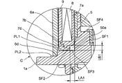
- the first annular space 50a is an annular space having a substantially rectangular cross section partitioned by four surfaces SF1 to SF4.
- 1st surface SF1 is the surface formed in the flange part 1a vicinity among the outer peripheral surfaces of the fixed iron core 1b.
- the second surface SF2 is formed at a position separated from the first surface SF1 of the surface of the exterior mold 9 by a distance LA1 in a direction (left and right direction in FIG. 3) perpendicular to the axial direction (up and down direction in FIG. 3). This is the surface facing the first surface SF1.
- the third surface SF3 is a surface formed on the annular support surface PL1 of the flange portion 1a.
- the fourth surface SF4 is a surface that is not in close contact with the exterior mold 9 among the surfaces of the bowl-shaped member 7b of the bobbin 7, and is formed at a position separated from the third surface SF3 by the distance LB1 in the axial direction. This is the surface facing the surface SF3.
- the position PT1 where the first surface SF1 is in close contact with the O-ring 11 and the second surface SF2 are the O-ring 11.
- the position PT2 in close contact with the second surface SF2 is formed on the third surface SF3 side in the axial direction (vertical direction in FIG. 5A) from the intersection point PT3 where the second surface SF2 and the fourth surface SF4 intersect.
- the boundary between the outer mold 9 and the flanged member 7b of the bobbin 7 is at the position of the intersection PT3, and the intersection PT3 is located on the inner side (axial direction) of the positions PT1 and PT2 where the O-ring 11 is in close contact with the surfaces SF1 and SF2.
- the boundary between the exterior mold 9 and the bowl-shaped member 7b of the bobbin 7 is defined by the O-ring 11 because it is on the fourth surface SF4 side from PT1 and PT2 (ie, above PT1 and PT2 in FIG. 5A). It will be located inside the position to be sealed.
- the O-ring 11 is in close contact with the first surface SF1 at the position of PT1, and the second at the position of PT2. Since it is in close contact with the surface SF2, it is usually impossible for water to enter the boundary portion between the outer mold 9 and the flanged member 7b of the bobbin 7, that is, the position of PT3.
- the first annular space 50a is located at a level higher than the annular step surface PL2, it is difficult for water to reach the annular support surface PL1 from the annular step surface PL2. Therefore, in the example of this embodiment, it is possible to reliably prevent water from entering the coil 8.
- the sealing performance is stable. Further, since the outer mold 9 is wound around the protrusion 7d, even if the O-ring 11 deteriorates and the sealing performance is lowered, water gets over the protrusion 7d and enters the coil 8. Since it is almost difficult to come, there is almost no problem that the coil 8 is short-circuited.
- the second annular space 50b is an annular space having a substantially rectangular cross section partitioned by four surfaces SF5 to SF8.
- the fifth surface SF5 is a surface formed at the end of the bottom 2a of the yoke 2.
- the sixth surface SF6 is formed at a position separated from the fifth surface SF5 of the surface of the exterior mold 9 by a distance LA2 in a direction (left-right direction in FIG. 4) perpendicular to the axial direction (up-down direction in FIG. 4). This is the surface facing the fifth surface SF5.
- the seventh surface SF7 is a surface formed on the back surface of the lid member 6b.
- the eighth surface is a surface that is not in close contact with the exterior mold 9 among the surfaces of the bowl-shaped member 7c of the bobbin 7, and is formed at a position separated from the seventh surface SF7 by a distance LB2 in the axial direction. This is the surface facing SF7.
- the boundary between the outer mold 9 and the flange-shaped member 7c of the bobbin 7 is at the position of the intersection point PT6, and the intersection point PT6 is inside the positions PT4 and PT5 where the O-ring 12 is in close contact with the surfaces SF5 and SF6 (axial direction).
- the boundary between the exterior mold 9 and the flange-like member 7c of the bobbin 7 is the O-ring 12 because it is on the eighth surface SF8 side from PT4 and PT5, that is, below PT4 and PT5 in FIG. It will be located inside the position sealed by.
- the O-ring 12 is in close contact with the fifth surface SF5 at the position of PT4, and the water is in contact with the fifth surface SF5 at the position of PT5. Since it is in close contact with the six-surface SF6, it is not normally possible for water to enter the boundary portion between the outer mold 9 and the flange-shaped member 7c of the bobbin 7, that is, the position of PT6. Therefore, in the example of the present embodiment, water can be prevented from entering the coil 8.
- the inner housing H Next, a method for manufacturing the inner housing H will be described. First, with the plunger 3 included, one end of the ring 5 is fitted into the first step 2e of the yoke 2 and the other end of the ring 5 is fitted into the second step 1g of the stator 1. The first step of assembling H is performed. The work contents of the first step will be specifically described. First, the stopper 10 is press-fitted into the through hole 1c of the stator 1 from the base end face 1d side, and then the end face of the ring 5 is inserted into the second step portion 1g of the stator 1. Press fit until contact.
- the plunger 3 is attached to the stator 1 while the plunger 3 into which the pin 4 is press-fitted is inserted into the through hole 1 c of the stator 1.
- press fitting is performed until the end surface of the first step portion 2 e of the yoke 2 contacts the ring 5.
- the plunger 3 is enclosed in the inner housing H.
- the second step is performed in which the butted portion between the end face on one end side of the ring 5 and the first stepped portion 2e of the yoke 2 is joined by butt welding.
- the details of the work in the second step will be described in detail.
- a preliminary check for welding the yoke 2 and the ring 5 is performed, such as whether the gap between the abutting portions of the stepped portion 2e and the end face of the ring 5 is uniform.
- the first stepped portion 2e of the yoke 2 and the butted portion (A portion in FIG. 2) of the end surface of the ring 5 are joined over the entire circumference by laser welding.
- the third step is performed in which the other end of the ring 5 and the second step portion 1g of the stator 1 are joined by lap welding.
- the details of the work in the third step will be described in detail.
- the stator 1 is tilted with respect to the yoke 2 and is not fitted in the ring 5 or between the second step portion 1g of the stator 1 and the end face of the ring 5.
- a preliminary check for welding the stator 1 and the ring 5 is performed, such as whether the gap between the abutting portions is uniform.
- the overlapping portion between the ring 5 and the second step portion 1g of the stator 1 is joined over the entire circumference by laser welding. The quality control in the welding process is more severe in the second process than in the third process.
- the welding line is predetermined in a direction (downward direction in FIG. 2) opposite to a direction (upward direction in FIG. 2) in which an annular member constituting the magnetic control unit 1e protrudes from the base end surface 1d of the stator 1. They are formed at positions separated by a distance X (position B in FIG. 2).
- the inner housing H is completed by performing the operations from the first to third steps.
- the directional control valve unit SP is coaxially attached to the electromagnetic drive unit DR in the electromagnetic drive unit DR configured as described above.
- This directional control valve unit SP includes a sleeve-like valve casing 30 and a spool 23 provided coaxially therein.
- the valve casing 30 has a supply port 31 connected to a hydraulic pump (not shown), an output port 32 connected to an actuator (not shown), and a drain port 33 connected to a tank (not shown). And are provided.
- the spool 23 is attached so that one end side thereof is in contact with the pin 4 of the electromagnetic drive unit DR, and the spool 23 moves in the axial direction as the pin 4 moves in the axial direction.
- a spring 24 is wound around the spool 23.
- One end of the spring 24 is locked to the inner wall of the valve casing 30, and the other end is in contact with an annular shim 25 fitted into the spool 23. Therefore, the spool 23 is accommodated in the valve casing 30 in a state where the spool 23 is always pressed toward the stator 1 (upward in FIG. 1) by the urging force of the spring 24.
- two land portions 36 and 37 are provided on the outer peripheral surface of the spool 23.
- the supply port 31 and the output port 32 are closed, but the spool 23 is movable in the axial direction.
- the supply port 31 and the output port 32 communicate with each other, and the pressure oil supplied from the hydraulic pump to the supply port 31 flows between the valve casing 30 and the spool 23. It flows through the space between them and exits from the output port 32 and is guided to the actuator.
- the flow path 38 is provided along the axis of the spool 23.
- the flow path 38 communicates with an inlet 39 and an outlet 40 formed on the outer peripheral surface of the spool 23.
- the oil in the tank is guided from the drain port 33 to the inlet 39, flows out of the outlet 40 through the flow path 38, and passes through the through hole 1 c from the end face of the flange portion 1 a of the stator 1 as it is. It is led into the inner housing H of the DR. Then, the oil guided into the inner housing H flows through the through hole 3 b of the plunger 3 into the space between the plunger 3 and the bottom 2 a of the yoke 2.
- valve casing 30 is surrounded by a case (not shown) including flow paths separately connected to the three ports 31, 32, 33, and an O-ring externally fitted to the valve casing 30 is between these flow paths. 21 and 22 are isolated.
- the solenoid valve SOV composed of the electromagnetic drive unit DR and the direction control valve unit SP will be described.
- the solenoid valve SOV is connected to a power source.
- This power supply may be either a DC power supply or an AC power supply.
- DC12V or DC24V can be used as the DC power supply
- AC100V (50/60 Hz) or AC200V can be used as the AC power supply.
- the spool 23 In the initial state in which no power is supplied to the coil 8, as shown in FIG. 1, the spool 23 is biased toward the stator 1 by the spring 24, so that the supply port 31 and the output port 32 communicate with each other. And the drain port 33 are closed.
- the O-rings 11 and 12 are in close contact with the two members of the exterior mold 9 and the inner housing H, compared with the seal structure in which the O-ring is in close contact with the three members.
- the variation in the dimension of the close contact surface of the O-ring is reduced. Therefore, stable sealing performance is exhibited.
- the inner housing H it is only necessary to join the stator 1, the ring 5 and the yoke 2 by welding, and there is no need to machine the inner peripheral surface of the inner housing H after welding. Accordingly, the number of processing steps can be reduced, and the inner housing can be manufactured at a low cost and with a short delivery time.
- the yoke 2 and the ring 5 are joined by butt welding, deformation or the like due to the welding of the yoke 2 is suppressed, and the movement of the plunger 3 is kept good.
- the stator 1 and the ring 5 are joined by lap welding, labor and time required for welding can be reduced, which can greatly contribute to cost reduction.
- the lap welding line is formed at a distance X from the base end surface 1d by a distance X, there is no concern that the magnetic control unit 1d changes its magnetism due to the heat effect of lap welding. .
- the manufacturing method is such that the third step of lap welding the ring 5 and the stator 1 is performed after the second step of butt welding the ring 5 and the yoke 2, variation in welding quality can be suppressed. The management of the welding process can be simplified.
- the exterior mold 9 has a structure in which the protrusions 7d and 7e are wound, but a structure of the bobbin 7 in which the protrusions 7d and 7e are not provided can also be adopted.
- the exterior mold 9 may be configured to wrap around the outer surface of the bobbin 7 without the protrusions 7d and 7e.
- the outer mold 9 and the inner housing H can be in close contact with the O-ring to seal the gap between the inner housing H and the solenoid assembly SA. Can exhibit stable sealing performance.
- it can also be set as the structure which provided multiple protrusion part 7d, 7e. According to such a configuration, since the water intrusion into the coil 8 is further prevented, the sealing performance is improved.
- the first annular space 50a has a relationship in which an arbitrary cross section of the space 50a has a distance LA1 ⁇ outer diameter OD1 ⁇ distance LB1 when the outer diameter of the O-ring 11 is OD1.
- an arbitrary cross section of the space 50b satisfies the relationship of “distance LA2 ⁇ outer diameter OD2 ⁇ distance LB2”.
- a configuration satisfying the relationship of “distance LA2 ⁇ distance LB2 ⁇ outer diameter OD2” may be employed.
- Stator 1a Flange 1b Fixed Iron Core (Body) 1d Base end face 1e Magnetic control part 1g Second step part 2 Yoke (body part) 2e 1st step part 3 Plunger 5 Ring (cylindrical member) (body part) 6 Case 6a Case body 6b Lid member 6c Opening 6d End face 7 Bobbin 7a Bobbin body 7b, 7c Hook-like member 7d, 7e Protruding part 8 Coil 9 Exterior mold 11 O-ring (first seal member) 12 O-ring (second seal member) 50a First annular space 50b Second annular space SF1 to SF8 First surface to eighth surface PL1 Annular support surface PL2 Annular step surface H Inner housing SA Solenoid assembly DR Electromagnetic drive unit SP Direction control valve unit (driven device) SOV solenoid valve
Landscapes
- Physics & Mathematics (AREA)
- Electromagnetism (AREA)
- Engineering & Computer Science (AREA)
- Power Engineering (AREA)
- General Engineering & Computer Science (AREA)
- Mechanical Engineering (AREA)
- Magnetically Actuated Valves (AREA)
- Electromagnets (AREA)
Abstract
Description
1a フランジ部
1b 固定鉄心(胴体部)
1d 基端面
1e 磁気制御部
1g 第2段差部
2 ヨーク(胴体部)
2e 第1段差部
3 プランジャ
5 リング(円筒状部材)(胴体部)
6 ケース
6a ケース本体
6b 蓋部材
6c 開口
6d 端面
7 ボビン
7a ボビン本体
7b、7c 鍔状部材
7d、7e 突起部
8 コイル
9 外装モールド
11 Oリング(第1シール部材)
12 Oリング(第2シール部材)
50a 第1環状空間
50b 第2環状空間
SF1~SF8 第1表面~第8表面
PL1 環状支持面
PL2 環状段差面
H インナハウジング
SA ソレノイドアッセンブリ
DR 電磁式駆動ユニット
SP 方向制御弁ユニット(被駆動装置)
SOV 電磁弁
Claims (5)
- プランジャを内包するインナハウジングと、このインナハウジングを囲むように取り付けられ、給電制御により前記プランジャを軸心方向に可動させるソレノイドアッセンブリと、このソレノイドアッセンブリを覆うケースとを備え、前記インナハウジングは、一端面側に被駆動装置が取り付けられるフランジ部と、このフランジ部の他端面側に設けられ、前記プランジャの可動を案内する内周面を有する中空の胴体部とを有し、前記ソレノイドアッセンブリは、ボビンと、このボビンに巻き掛けられたコイルと、このコイルが巻き掛けられた状態の前記ボビンを外側から包む外装モールドとを有する電磁式駆動ユニットであって、
前記胴体部を前記ボビンに挿入して前記インナハウジングに前記ソレノイドアッセンブリが取り付けられると、前記インナハウジングと前記ソレノイドアッセンブリとの間に、環状の第1シール部材を装着するための第1環状空間が形成され、
前記第1環状空間は、前記胴体部の周囲に沿って形成された環状の空間であって、前記胴体部の外周面のうち前記フランジ部近傍に形成された第1表面と、前記外装モールドの表面のうち前記第1表面から前記軸心方向と直交する方向に距離LA1だけ隔てた位置に形成され、前記第1表面と対面する第2表面と、前記フランジ部の前記他端面に形成された第3表面と、前記ボビンの表面のうち前記第3表面から前記軸心方向に距離LB1だけ隔てた位置に形成され、前記第3表面と対面する第4表面とにより仕切られていると共に、前記第1シール部材の外径をOD1としたときに、当該空間の任意の断面が、距離LA1<外径OD1、かつ、距離LA1<距離LB1の関係を満たす略矩形形状を成し、
前記第1環状空間に前記第1シール部材が装着された状態での前記第1環状空間の断面において、前記第1表面および前記第2表面が前記第1シール部材とそれぞれ密着する位置は、前記第2表面と前記第4表面とが交わる交点より前記軸心方向で前記第3表面側に形成されるようにした
ことを特徴とする電磁式駆動ユニット。 - 請求項1の記載において、
前記ボビンは、円筒形状のボビン本体と、このボビン本体の両端から外方に折れ曲がる一対の鍔状部材とを備えると共に、前記一対の鍔状部材には、前記軸心方向に沿って互いに離隔する方向に突出する突起部がそれぞれ設けられており、
前記外装モールドは、前記突起部を巻き込むようにして前記ボビンを外側から包む構成から成る
ことを特徴とする電磁式駆動ユニット。 - 請求項1または2の記載において、
前記フランジ部の前記他端面は、前記胴体部の周囲に沿って円環状に形成され、前記外装モールドを支持する環状支持面と、この環状支持面から連続して円環状に形成され、当該環状支持面より一段低い位置にある環状段差面とを有し、
前記第3表面は前記環状支持面に形成され、
前記ケースは、その端面が前記環状段差面と当接した状態で前記ソレノイドアッセンブリを覆う構成から成る
ことを特徴とする電磁式駆動ユニット。 - 請求項1~3のいずれか1項の記載において、
前記ケースは、円筒形状のケース本体と、このケース本体の一端を塞ぐ蓋部材とを有すると共に、前記蓋部材に前記胴体部が貫通する開口が設けられ、
前記インナハウジングに取り付けられた前記ソレノイドアッセンブリを前記ケースで覆うと、前記開口から前記胴体部の先端部が露出し、前記ケースと前記ソレノイドアッセンブリと前記インナハウジングとの間に、環状の第2シール部材を装着するための第2環状空間が形成され、
前記第2環状空間は、前記胴体部の周囲に沿って形成された環状の空間であって、前記胴体部の外周面のうち前記フランジ部と反対側の端部に形成された第5表面と、前記外装モールドの表面のうち前記第5表面から前記軸心方向と直交する方向に距離LA2だけ隔てた位置に形成され、前記第5表面と対面する第6表面と、前記蓋部材の裏面に形成された第7表面と、前記ボビンの表面のうち前記第7表面から前記軸心方向に距離LB2だけ隔てた位置に形成され、前記第7表面と対面する第8表面とにより仕切られていると共に、前記第2シール部材の外径をOD2としたときに、当該空間の任意の断面が、距離LA2<外径OD2、かつ、距離LA2<距離LB2の関係を満たす略矩形形状を成し、
前記第2環状空間に前記第2シール部材が装着された状態での前記第2環状空間の断面において、前記第5表面および前記第6表面が前記第2シール部材とそれぞれ密着する位置は、前記第6表面と前記第8表面とが交わる交点より前記軸心方向で前記第7表面側に形成されるようにした
ことを特徴とする電磁式駆動ユニット。 - 請求項1~4のいずれか1項の記載において、
前記インナハウジングは、磁性体材料から成るステータと、このステータと同軸上に配置され、磁性体材料から成るヨークと、非磁性体材料から成り、前記ステータと前記ヨークとの間の位置で、かつ前記ステータと同軸上に配置されると共に前記ステータと前記ヨークとを一体的に繋ぐ円筒状部材とを有して成り、
前記ステータは、前記フランジ部と、このフランジ部の前記他端面から前記軸心方向に突出する固定鉄心とを備え、
前記胴体部は、前記固定鉄心と、前記ヨークと、前記円筒状部材とを含んで構成されると共に、前記ヨークに前記プランジャの可動を案内する前記内周面が形成され、
前記ヨークの外周面のうち前記ステータ側の端部には、一段低い第1段差部が形成され、
前記固定鉄心は、前記プランジャと対面する基端面を有し、前記基端面には、軸方向に突出する円環状の部材であって磁力を制御する磁気制御部が設けられると共に、前記固定鉄心の外周面のうち前記基端面側の端部には、一段低い第2段差部が形成され、
前記円筒状部材は、一端側の内径が前記第1段差部の外径と略同一、かつ他端側の内径が前記第2段差部の外径と略同一になるよう形成され、
前記インナハウジングは、前記円筒状部材の一端側を前記第1段差部に嵌め込んだ状態で前記円筒状部材と前記ヨークとを溶接により接合し、前記円筒状部材の他端側を前記第2段差部に嵌め込んだ状態で前記円筒状部材と前記ステータとを溶接により接合することにより形成される
ことを特徴とする電磁式駆動ユニット。
Priority Applications (3)
| Application Number | Priority Date | Filing Date | Title |
|---|---|---|---|
| KR1020137005664A KR101829943B1 (ko) | 2010-08-06 | 2011-07-28 | 전자기식 구동 유닛 |
| EP11814545.7A EP2590184A4 (en) | 2010-08-06 | 2011-07-28 | ELECTROMAGNETIC DRIVE UNIT |
| CN201180038800.7A CN103069513B (zh) | 2010-08-06 | 2011-07-28 | 电磁式驱动单元 |
Applications Claiming Priority (2)
| Application Number | Priority Date | Filing Date | Title |
|---|---|---|---|
| JP2010177555A JP5601929B2 (ja) | 2010-08-06 | 2010-08-06 | 電磁式駆動ユニット |
| JP2010-177555 | 2010-08-06 |
Publications (1)
| Publication Number | Publication Date |
|---|---|
| WO2012017918A1 true WO2012017918A1 (ja) | 2012-02-09 |
Family
ID=45559419
Family Applications (1)
| Application Number | Title | Priority Date | Filing Date |
|---|---|---|---|
| PCT/JP2011/067286 Ceased WO2012017918A1 (ja) | 2010-08-06 | 2011-07-28 | 電磁式駆動ユニット |
Country Status (5)
| Country | Link |
|---|---|
| EP (1) | EP2590184A4 (ja) |
| JP (1) | JP5601929B2 (ja) |
| KR (1) | KR101829943B1 (ja) |
| CN (1) | CN103069513B (ja) |
| WO (1) | WO2012017918A1 (ja) |
Cited By (1)
| Publication number | Priority date | Publication date | Assignee | Title |
|---|---|---|---|---|
| CN105190796A (zh) * | 2013-05-08 | 2015-12-23 | Eto电磁有限责任公司 | 电磁调整设备 |
Families Citing this family (6)
| Publication number | Priority date | Publication date | Assignee | Title |
|---|---|---|---|---|
| JP2014017282A (ja) * | 2012-07-05 | 2014-01-30 | Mikuni Corp | 電磁アクチュエータ |
| EP3933860B1 (en) | 2016-04-08 | 2022-12-07 | Eagle Industry Co., Ltd. | Solenoid |
| CN108755681B (zh) * | 2018-07-02 | 2020-06-12 | 南安市科体机械科技有限公司 | 一种土木建筑用水面夯实器 |
| JP7383907B2 (ja) * | 2019-06-04 | 2023-11-21 | 株式会社ジェイテクト | 電磁弁 |
| EP3800650A1 (en) * | 2019-10-01 | 2021-04-07 | HUSCO Automotive Holdings LLC | Dual-flanged unitary pole piece and electromagnetic actuator including the dual-flanged unitary pole piece |
| JP7785545B2 (ja) * | 2022-01-07 | 2025-12-15 | 株式会社ジェイテクトフルードパワーシステム | 電磁弁 |
Citations (6)
| Publication number | Priority date | Publication date | Assignee | Title |
|---|---|---|---|---|
| JPH043452A (ja) | 1990-04-20 | 1992-01-08 | Toshiba Corp | 樹脂封止型半導体装置 |
| JPH09320840A (ja) * | 1996-05-30 | 1997-12-12 | Aichi Electric Co Ltd | ソレノイド装置 |
| JP2000145567A (ja) * | 1998-11-12 | 2000-05-26 | Aisan Ind Co Ltd | 電磁式燃料噴射弁 |
| JP2008232440A (ja) * | 2008-04-18 | 2008-10-02 | Kawasaki Precision Machinery Ltd | 電磁弁装置 |
| JP2009085321A (ja) * | 2007-09-28 | 2009-04-23 | Keihin Corp | 電磁弁 |
| JP2009085322A (ja) * | 2007-09-28 | 2009-04-23 | Keihin Corp | 電磁アクチュエータ |
Family Cites Families (6)
| Publication number | Priority date | Publication date | Assignee | Title |
|---|---|---|---|---|
| JPS57162306A (en) * | 1981-03-30 | 1982-10-06 | Ckd Controls Ltd | Stationary core for solenoid |
| JP2003185051A (ja) * | 2001-12-13 | 2003-07-03 | Denso Corp | 電磁弁装置およびその製造方法 |
| DE10239207A1 (de) * | 2002-08-27 | 2004-03-11 | Ina-Schaeffler Kg | Elektromagnetisches Hydraulikventil, insbesondere Proportionalventil zur Steuerung einer Vorrichtung zur Drehwinkelverstellung einer Nockenwelle gegenüber einer Kurbelwelle einer Brennkraftmaschine |
| JP4428027B2 (ja) * | 2003-11-12 | 2010-03-10 | 株式会社デンソー | 電磁駆動装置およびそれを用いた電磁弁 |
| DE102007036924A1 (de) * | 2007-08-04 | 2009-02-05 | Schaeffler Kg | Elektromagnetische Stelleinheit |
| JP5604212B2 (ja) * | 2010-08-03 | 2014-10-08 | 日立建機株式会社 | 電磁式駆動ユニットおよびその製造方法 |
-
2010
- 2010-08-06 JP JP2010177555A patent/JP5601929B2/ja active Active
-
2011
- 2011-07-28 WO PCT/JP2011/067286 patent/WO2012017918A1/ja not_active Ceased
- 2011-07-28 EP EP11814545.7A patent/EP2590184A4/en not_active Withdrawn
- 2011-07-28 KR KR1020137005664A patent/KR101829943B1/ko active Active
- 2011-07-28 CN CN201180038800.7A patent/CN103069513B/zh active Active
Patent Citations (6)
| Publication number | Priority date | Publication date | Assignee | Title |
|---|---|---|---|---|
| JPH043452A (ja) | 1990-04-20 | 1992-01-08 | Toshiba Corp | 樹脂封止型半導体装置 |
| JPH09320840A (ja) * | 1996-05-30 | 1997-12-12 | Aichi Electric Co Ltd | ソレノイド装置 |
| JP2000145567A (ja) * | 1998-11-12 | 2000-05-26 | Aisan Ind Co Ltd | 電磁式燃料噴射弁 |
| JP2009085321A (ja) * | 2007-09-28 | 2009-04-23 | Keihin Corp | 電磁弁 |
| JP2009085322A (ja) * | 2007-09-28 | 2009-04-23 | Keihin Corp | 電磁アクチュエータ |
| JP2008232440A (ja) * | 2008-04-18 | 2008-10-02 | Kawasaki Precision Machinery Ltd | 電磁弁装置 |
Non-Patent Citations (1)
| Title |
|---|
| See also references of EP2590184A4 * |
Cited By (3)
| Publication number | Priority date | Publication date | Assignee | Title |
|---|---|---|---|---|
| CN105190796A (zh) * | 2013-05-08 | 2015-12-23 | Eto电磁有限责任公司 | 电磁调整设备 |
| CN105190796B (zh) * | 2013-05-08 | 2017-05-17 | Eto电磁有限责任公司 | 电磁调整设备 |
| US9761363B2 (en) | 2013-05-08 | 2017-09-12 | Eto Magnetic Gmbh | Electromagnetic actuating apparatus |
Also Published As
| Publication number | Publication date |
|---|---|
| EP2590184A4 (en) | 2016-02-17 |
| KR20130094315A (ko) | 2013-08-23 |
| KR101829943B1 (ko) | 2018-02-19 |
| JP2012038910A (ja) | 2012-02-23 |
| EP2590184A1 (en) | 2013-05-08 |
| CN103069513A (zh) | 2013-04-24 |
| CN103069513B (zh) | 2015-09-02 |
| JP5601929B2 (ja) | 2014-10-08 |
Similar Documents
| Publication | Publication Date | Title |
|---|---|---|
| JP5601929B2 (ja) | 電磁式駆動ユニット | |
| JP5604212B2 (ja) | 電磁式駆動ユニットおよびその製造方法 | |
| US9624948B2 (en) | Electromagnetic valve | |
| JP5307517B2 (ja) | ソレノイド | |
| JP5299499B2 (ja) | 電磁ソレノイド | |
| EP0428728A1 (en) | Electromagnet for solenoid valve and production method of the same | |
| JP6115434B2 (ja) | 電磁弁 | |
| JP2010065780A (ja) | 電磁開閉弁 | |
| JP2009287663A (ja) | 流量制御弁 | |
| JP2012204574A (ja) | リニアソレノイド | |
| JP4315220B2 (ja) | バルブ装置 | |
| US6634381B2 (en) | Solenoid valve device and its manufacturing method | |
| JP4703615B2 (ja) | ブリード式バルブ装置 | |
| JP2013087807A (ja) | スプール制御弁 | |
| JP4613773B2 (ja) | バルブ装置 | |
| US12366304B2 (en) | Solenoid valve | |
| JP6169453B2 (ja) | 圧力流体制御装置 | |
| JP5296504B2 (ja) | ソレノイド | |
| JP2014240682A (ja) | 流体制御弁装置 | |
| JP2005276927A (ja) | 油浸形ソレノイド | |
| KR101947904B1 (ko) | 솔레노이드밸브 벤트 구조 | |
| JP5301243B2 (ja) | ソレノイド | |
| JP5659032B2 (ja) | 電磁式駆動ユニット | |
| JP2006336766A (ja) | 電磁式駆動ユニット | |
| JP2019211021A (ja) | 流量制御弁 |
Legal Events
| Date | Code | Title | Description |
|---|---|---|---|
| WWE | Wipo information: entry into national phase |
Ref document number: 201180038800.7 Country of ref document: CN |
|
| 121 | Ep: the epo has been informed by wipo that ep was designated in this application |
Ref document number: 11814545 Country of ref document: EP Kind code of ref document: A1 |
|
| WWE | Wipo information: entry into national phase |
Ref document number: 2011814545 Country of ref document: EP |
|
| NENP | Non-entry into the national phase |
Ref country code: DE |
|
| ENP | Entry into the national phase |
Ref document number: 20137005664 Country of ref document: KR Kind code of ref document: A |