WO2012026545A1 - 空気入りタイヤ - Google Patents
空気入りタイヤ Download PDFInfo
- Publication number
- WO2012026545A1 WO2012026545A1 PCT/JP2011/069218 JP2011069218W WO2012026545A1 WO 2012026545 A1 WO2012026545 A1 WO 2012026545A1 JP 2011069218 W JP2011069218 W JP 2011069218W WO 2012026545 A1 WO2012026545 A1 WO 2012026545A1
- Authority
- WO
- WIPO (PCT)
- Prior art keywords
- main groove
- land portion
- circumferential
- tire
- inclined surface
- Prior art date
- Legal status (The legal status is an assumption and is not a legal conclusion. Google has not performed a legal analysis and makes no representation as to the accuracy of the status listed.)
- Ceased
Links
Images






Classifications
-
- B—PERFORMING OPERATIONS; TRANSPORTING
- B60—VEHICLES IN GENERAL
- B60C—VEHICLE TYRES; TYRE INFLATION; TYRE CHANGING; CONNECTING VALVES TO INFLATABLE ELASTIC BODIES IN GENERAL; DEVICES OR ARRANGEMENTS RELATED TO TYRES
- B60C11/00—Tyre tread bands; Tread patterns; Anti-skid inserts
- B60C11/03—Tread patterns
- B60C11/04—Tread patterns in which the raised area of the pattern consists only of continuous circumferential ribs, e.g. zig-zag
- B60C11/042—Tread patterns in which the raised area of the pattern consists only of continuous circumferential ribs, e.g. zig-zag further characterised by the groove cross-section
- B60C11/045—Tread patterns in which the raised area of the pattern consists only of continuous circumferential ribs, e.g. zig-zag further characterised by the groove cross-section the groove walls having a three-dimensional shape
-
- B—PERFORMING OPERATIONS; TRANSPORTING
- B60—VEHICLES IN GENERAL
- B60C—VEHICLE TYRES; TYRE INFLATION; TYRE CHANGING; CONNECTING VALVES TO INFLATABLE ELASTIC BODIES IN GENERAL; DEVICES OR ARRANGEMENTS RELATED TO TYRES
- B60C11/00—Tyre tread bands; Tread patterns; Anti-skid inserts
- B60C11/03—Tread patterns
- B60C11/0306—Patterns comprising block rows or discontinuous ribs
-
- B—PERFORMING OPERATIONS; TRANSPORTING
- B60—VEHICLES IN GENERAL
- B60C—VEHICLE TYRES; TYRE INFLATION; TYRE CHANGING; CONNECTING VALVES TO INFLATABLE ELASTIC BODIES IN GENERAL; DEVICES OR ARRANGEMENTS RELATED TO TYRES
- B60C11/00—Tyre tread bands; Tread patterns; Anti-skid inserts
- B60C11/03—Tread patterns
- B60C11/12—Tread patterns characterised by the use of narrow slits or incisions, e.g. sipes
-
- B—PERFORMING OPERATIONS; TRANSPORTING
- B60—VEHICLES IN GENERAL
- B60C—VEHICLE TYRES; TYRE INFLATION; TYRE CHANGING; CONNECTING VALVES TO INFLATABLE ELASTIC BODIES IN GENERAL; DEVICES OR ARRANGEMENTS RELATED TO TYRES
- B60C11/00—Tyre tread bands; Tread patterns; Anti-skid inserts
- B60C11/03—Tread patterns
- B60C11/12—Tread patterns characterised by the use of narrow slits or incisions, e.g. sipes
- B60C11/1236—Tread patterns characterised by the use of narrow slits or incisions, e.g. sipes with special arrangements in the tread pattern
- B60C11/125—Tread patterns characterised by the use of narrow slits or incisions, e.g. sipes with special arrangements in the tread pattern arranged at the groove bottom
-
- B—PERFORMING OPERATIONS; TRANSPORTING
- B60—VEHICLES IN GENERAL
- B60C—VEHICLE TYRES; TYRE INFLATION; TYRE CHANGING; CONNECTING VALVES TO INFLATABLE ELASTIC BODIES IN GENERAL; DEVICES OR ARRANGEMENTS RELATED TO TYRES
- B60C11/00—Tyre tread bands; Tread patterns; Anti-skid inserts
- B60C11/03—Tread patterns
- B60C11/13—Tread patterns characterised by the groove cross-section, e.g. for buttressing or preventing stone-trapping
-
- B—PERFORMING OPERATIONS; TRANSPORTING
- B60—VEHICLES IN GENERAL
- B60C—VEHICLE TYRES; TYRE INFLATION; TYRE CHANGING; CONNECTING VALVES TO INFLATABLE ELASTIC BODIES IN GENERAL; DEVICES OR ARRANGEMENTS RELATED TO TYRES
- B60C11/00—Tyre tread bands; Tread patterns; Anti-skid inserts
- B60C11/03—Tread patterns
- B60C11/13—Tread patterns characterised by the groove cross-section, e.g. for buttressing or preventing stone-trapping
- B60C11/1307—Tread patterns characterised by the groove cross-section, e.g. for buttressing or preventing stone-trapping with special features of the groove walls
- B60C11/1323—Tread patterns characterised by the groove cross-section, e.g. for buttressing or preventing stone-trapping with special features of the groove walls asymmetric
-
- B—PERFORMING OPERATIONS; TRANSPORTING
- B60—VEHICLES IN GENERAL
- B60C—VEHICLE TYRES; TYRE INFLATION; TYRE CHANGING; CONNECTING VALVES TO INFLATABLE ELASTIC BODIES IN GENERAL; DEVICES OR ARRANGEMENTS RELATED TO TYRES
- B60C11/00—Tyre tread bands; Tread patterns; Anti-skid inserts
- B60C11/03—Tread patterns
- B60C11/13—Tread patterns characterised by the groove cross-section, e.g. for buttressing or preventing stone-trapping
- B60C11/1369—Tie bars for linking block elements and bridging the groove
-
- B—PERFORMING OPERATIONS; TRANSPORTING
- B60—VEHICLES IN GENERAL
- B60C—VEHICLE TYRES; TYRE INFLATION; TYRE CHANGING; CONNECTING VALVES TO INFLATABLE ELASTIC BODIES IN GENERAL; DEVICES OR ARRANGEMENTS RELATED TO TYRES
- B60C11/00—Tyre tread bands; Tread patterns; Anti-skid inserts
- B60C11/03—Tread patterns
- B60C11/13—Tread patterns characterised by the groove cross-section, e.g. for buttressing or preventing stone-trapping
- B60C11/1376—Three dimensional block surfaces departing from the enveloping tread contour
- B60C11/1392—Three dimensional block surfaces departing from the enveloping tread contour with chamfered block edges
-
- B—PERFORMING OPERATIONS; TRANSPORTING
- B60—VEHICLES IN GENERAL
- B60C—VEHICLE TYRES; TYRE INFLATION; TYRE CHANGING; CONNECTING VALVES TO INFLATABLE ELASTIC BODIES IN GENERAL; DEVICES OR ARRANGEMENTS RELATED TO TYRES
- B60C11/00—Tyre tread bands; Tread patterns; Anti-skid inserts
- B60C11/03—Tread patterns
- B60C2011/0337—Tread patterns characterised by particular design features of the pattern
- B60C2011/0339—Grooves
- B60C2011/0381—Blind or isolated grooves
- B60C2011/0383—Blind or isolated grooves at the centre of the tread
-
- B—PERFORMING OPERATIONS; TRANSPORTING
- B60—VEHICLES IN GENERAL
- B60C—VEHICLE TYRES; TYRE INFLATION; TYRE CHANGING; CONNECTING VALVES TO INFLATABLE ELASTIC BODIES IN GENERAL; DEVICES OR ARRANGEMENTS RELATED TO TYRES
- B60C11/00—Tyre tread bands; Tread patterns; Anti-skid inserts
- B60C11/03—Tread patterns
- B60C11/12—Tread patterns characterised by the use of narrow slits or incisions, e.g. sipes
- B60C11/1204—Tread patterns characterised by the use of narrow slits or incisions, e.g. sipes with special shape of the sipe
- B60C2011/1209—Tread patterns characterised by the use of narrow slits or incisions, e.g. sipes with special shape of the sipe straight at the tread surface
Definitions
- the present invention relates to a pneumatic tire.
- Patent Document 1 There is disclosed a structure in which a platform with a partially raised groove bottom at the end of the lateral groove of the tread is provided, and the collapse of the block to the lateral groove side is suppressed by contact with the platform (see Patent Document 1). Moreover, the structure which suppresses the amount of collapse of both ends of a block with a platform and tries to reduce the uneven wear of the whole block is disclosed (refer patent document 1). Furthermore, the structure which provided the block adjacent to the tire width direction outer side of the rib is disclosed (refer patent document 2 and patent document 3).
- the rigidity of the end on the circumferential main groove side of the block defined by the circumferential main groove and the horizontal main groove is locally reduced.
- the end of the block on the circumferential main groove side tends to fall down.
- the present invention aims to achieve both wet performance and steering stability performance in consideration of the above facts.
- a first aspect of the present invention is provided in a tread, and is partitioned by a circumferential main groove extending in the tire circumferential direction and a horizontal main groove extending in a direction intersecting the circumferential main groove and opening in the circumferential main groove.
- a land portion, an end portion of the horizontal main groove in the tread that opens to the circumferential main groove, the one land portion adjacent to the circumferential main groove in the tire circumferential direction, and the other land portion. Have crossing portions that cross each other so as to support each other in the tire width direction.
- the horizontal main groove formed in the tread extends in a direction intersecting the circumferential main groove and is open to the circumferential main groove. Water between the road surface and the road surface is discharged to the circumferential main groove through the horizontal main groove. For this reason, wet performance is securable.
- one end portion and the other land portion that are adjacent to the circumferential main groove in the lateral main groove are adjacent to the end portion of the lateral main groove in the circumferential direction of the tire. Since they have crossing portions that cross each other so as to support each other in the tire width direction, even when the tire has a large slip angle, the end portion of the land portion on the circumferential main groove side does not easily fall down. For this reason, steering stability can be ensured.
- the one land portion in the intersecting portion, is inclined in a tread depth direction toward the other land portion side.
- 1 inclined surface is formed, and the other land portion is inclined in the tread depth direction toward the one land portion side and intersects with the first inclined surface as viewed from the direction in which the horizontal main groove extends.
- Two inclined surfaces are formed, and the first inclined surface and the second inclined surface constitute a groove wall of the horizontal main groove at the intersection.
- the first inclined surface of one land portion and the second inclined surface of the other land portion intersect, Since the 1 inclined surface and the 2nd inclined surface comprise the groove wall of the horizontal main groove in an intersection part, while ensuring the drainage from this horizontal main groove to the circumferential direction main groove, one land part and the other
- the falling of the end portion on the circumferential main groove side of the land portion can be suppressed, and the steering stability can be ensured.
- the lateral main groove extends while being inclined with respect to the tire width direction, and the one land portion is , Located on the acute angle side of the intersection angle between the circumferential main groove and the transverse main groove at the intersection, the other land portion is located on the obtuse angle side of the intersection angle, and the one land portion It extends between the circumferential main grooves.
- the other land portion located on the obtuse angle side at the crossing portion extends between the one land portion located on the acute angle side and the circumferential main groove,
- the one land portion located on the acute angle side can be supported by the other land portion located on the obtuse angle side, and falling can be suppressed.
- the one land portion and the other land portion are continuous at the intersection. .
- the width of the horizontal main groove on the tread surface of the intersecting portion is the width of the circumferential main groove. Of 5 to 60%.
- the reason why the lower limit is set to 5% is that, if the lower limit is not reached, the groove volume is reduced and the drainage is extremely deteriorated. Also, the upper limit is set to 60% because if it exceeds this, the rigidity will drop and the steering stability will deteriorate.
- the ratio of the width of the horizontal main groove to the width of the main groove in the circumferential direction on the tread surface at the intersection is appropriately set, so that both wet performance and steering stability performance are highly compatible. Can be made.
- the depth of the horizontal main groove at the intersecting portion is the horizontal main groove other than the intersecting portion. 10 to 90% of the depth.
- the reason why the lower limit value is set to 10% is that, if the lower limit is not reached, the groove volume decreases and the drainage performance deteriorates.
- the reason why the upper limit value is 90% is that when the upper limit value is exceeded, the rigidity decreases and the steering stability performance deteriorates.
- an inclination angle of the first inclined surface with respect to a tire radial direction is 0 to 60 °.
- the reason why the lower limit value is set to 0 ° is that, if the lower limit is not reached, the groove volume decreases and the drainage performance deteriorates.
- the upper limit is set to 60 ° because if it exceeds this, the rigidity is lowered and the steering stability is deteriorated.
- the inclination angle of the second inclined surface with respect to the tire radial direction is 10 to 80 °.
- the reason why the lower limit value is set to 10 ° is that if the slip angle is below this value, the slope of the land on the acute angle side will fall more greatly.
- the reason why the upper limit value is set to 80 ° is that if the upper limit value is exceeded, drainage from the horizontal main groove to the circumferential main groove deteriorates.
- a tread is provided with a circumferential main groove extending in the tire circumferential direction and a transverse main groove extending in a direction intersecting the circumferential main groove and opening in the circumferential main groove.
- a land portion provided at the tread and open to the circumferential main groove in the transverse main groove, the one land portion adjacent to the tire circumferential direction of the transverse main groove and the other land portion.
- the top surface forming the bottom surface of the horizontal main groove is formed by inclined surfaces extending from the one land portion and the other land portion and inclined in the tread depth direction, respectively. And a bottom raised portion.
- the horizontal main groove formed in the tread extends in a direction intersecting the circumferential main groove and opens in the circumferential main groove, and the circumferential main groove Since the top surface that forms the bottom surface of the end that opens in the direction main groove has a bottom-up portion that is formed by an inclined surface that extends from one land portion and the other land portion and that inclines in the tread depth direction, respectively.
- wet performance is securable.
- the bottom raised portion is continuously and integrally formed between the one land portion and the other land portion at the end portion opened to the circumferential main groove in the horizontal main groove. Since the top surface of the raised portion is formed by the inclined surface, the end of the block is not locally stretched or local friction with respect to the road surface is less likely to occur when the tread contacts the ground. Become. For this reason, uneven wear resistance can be ensured.
- the pneumatic tire according to the ninth aspect can achieve both wet performance and uneven wear resistance.
- the horizontal main groove extends while being inclined with respect to the tire width direction, and the one land portion is at the bottom raised portion.
- the inclined surface Located on the acute angle side of the intersecting angle between the circumferential main groove and the lateral main groove, the inclined surface intersects the tire circumferential direction when viewed from the direction in which the lateral main groove extends, and the bottom raised portion is the one side And the other land portion are overlapped with each other in the tire width direction.
- the lateral main groove is inclined with respect to the tire width direction, and therefore has high drainage.
- the inclined surface intersects in the tire circumferential direction when viewed from the direction in which the lateral main groove extends, the bottom-up portion overlaps in the tire width direction on each side wall extending from one land portion and the other land portion,
- the raised portions can support each other with respect to the input in the tire width direction. Accordingly, even when the tire has a large slip angle, the end portion on the acute angle side of the land portion is unlikely to fall down. For this reason, wet performance and uneven wear resistance can be further improved.
- An eleventh aspect of the present invention is the pneumatic tire according to the tenth aspect, wherein the inclined surface extending from the other land portion in the bottom raised portion is between the one land portion and the circumferential main groove. It is extended to.
- the tire since the inclined surface extending from the other land portion at the bottom raised portion extends between the one land portion and the circumferential main groove, the tire has a large slip angle.
- one land portion located on the acute angle side can be supported by the other land portion located on the obtuse angle side, and falling can be suppressed.
- a rib extending in the tire circumferential direction is provided adjacent to the land portion in the tire width direction.
- a circumferential sipe formed shallower than the transverse main groove is provided between the rib and the land portion.
- the wet performance can be further improved by performing water removal during wet running with a circumferential sipe between the rib and the land portion. Moreover, since this circumferential sipe is shallower than the horizontal main groove, the land portion is reinforced by ribs. For this reason, uneven wear resistance can be further enhanced.
- the pneumatic tire according to the second aspect it is possible to obtain an excellent effect that it is possible to ensure drainage from the lateral main groove to the circumferential main groove and to ensure steering stability.
- the one land portion located on the acute angle side is supported by the other land portion located on the obtuse angle side to suppress the collapse.
- the excellent effect of being able to be obtained is obtained.
- the pneumatic tire according to the fourth aspect it is possible to obtain an excellent effect that the falling of the land portion when the tire has a large slip angle can be further suppressed.
- the pneumatic tire according to the fifth aspect it is possible to obtain an excellent effect that the steering stability performance of the wet performance can be made highly compatible.
- the pneumatic tire according to the sixth aspect it is possible to obtain an excellent effect that it is possible to ensure drainage in the horizontal main groove and to ensure steering stability.
- the pneumatic tire according to the seventh aspect it is possible to obtain an excellent effect that it is possible to ensure drainage in the horizontal main groove and to ensure steering stability.
- the pneumatic tire according to the eighth aspect it is possible to obtain an excellent effect that the drainage of the horizontal main groove can be ensured and the land portion on the acute angle side can be prevented from falling.
- the one land portion located on the acute angle side is supported by the other land portion located on the obtuse angle side to suppress the collapse.
- the excellent effect of being able to be obtained is obtained.
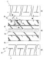
- FIG. 1 is a plan view showing a tread pattern of a pneumatic tire. It is an expansion perspective view which shows the structure of a cross
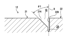
- FIG. 3B is a cross-sectional view taken along the 3B-3B arrow in FIG. 3A showing the horizontal main groove having the first inclined surface in the groove wall. It is 3C arrow line view in FIG. 3A which shows the horizontal main groove
- 4 to 6 relate to the second embodiment.
- FIG. 4 is a plan view and a cross-sectional view showing a tread pattern of a pneumatic tire.
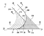
- FIG. 6B is a cross-sectional view taken along arrow 6B-6B in FIG. 6A, showing the horizontal main groove having the first inclined surface in the groove wall. It is a 6C arrow line view in FIG. 6A which shows the horizontal main groove
- FIG. 6B is a sectional end view taken along 6D-6D in FIG.
- a pneumatic tire 10 is provided on a tread 12 and extends in a direction intersecting the circumferential main grooves 14 and 15 extending in the tire circumferential direction and the circumferential main groove 14 in the circumferential direction.
- the land portions 21 and 22 defined by the horizontal main groove 16 that opens to the main groove 14 and the end portion of the horizontal main groove 16 that opens to the circumferential main groove 14 in the tread 12 are provided.
- One land portion 21 and the other land portion 22 adjacent to each other in the tire circumferential direction have a crossing portion 18 that intersects with each other so as to support each other in the tire width direction.
- the opening of the horizontal main groove 16 to the circumferential main groove 14 means that communication between the horizontal main groove 16 and the circumferential main groove 14 is ensured at the time of grounding.
- the circumferential main groove 15 is, for example, one groove located on the tire equatorial plane CL.
- the circumferential main groove 14 is located between the circumferential main groove 15 and the ground contact end T in the tire width direction.
- the lateral main groove 16 extends while being inclined with respect to the tire width direction.
- One land portion 21 and the other land portion 22 are central region land portions 30 close to the tire equator plane CL.
- the tread 12 is also provided with a shoulder region land portion 32 located on the outer side in the tire width direction from the central region land portion 30.
- the ground contact edge T means that the pneumatic tire 10 is mounted on a standard rim prescribed in JATMA YEAR BOOK (2009 edition, Japan Automobile Tire Association Standard), and applied size and ply rating in JATMA YEAR BOOK. This is the outermost end in the tire width direction when the maximum load capacity is loaded by filling the internal pressure at 100% of the air pressure (maximum air pressure) corresponding to the maximum load capacity (internal pressure-load capacity correspondence table in bold).
- the TRA standard or the ETRTO standard is applied in the place of use or manufacturing, the rim, air pressure, and load comply with the respective standards.
- the width WL of the horizontal main groove 16 on the tread surface of the intersection 18 is, for example, 5 to 60% of the width WR of the circumferential main groove 14.
- the reason why the lower limit of the percentage of WL / WR is set to 5% is that if the percentage is below this, the groove volume is reduced and the drainage is extremely deteriorated.
- the upper limit is set to 60% because if it exceeds this, the rigidity will drop and the steering stability will deteriorate.
- the wet performance and the steering stability performance can be highly compatible.
- the depth D1 of the horizontal main groove 16 at the intersecting portion 18 is, for example, 10 to 90% of the depth D2 of the horizontal main groove 16 other than the intersecting portion 18.
- the reason why the lower limit value of the percentage of D1 / D2 is set to 10% is that if it is less than this, the groove volume in the horizontal main groove 16 decreases and the drainage performance deteriorates.
- the reason why the upper limit value is 90% is that when the upper limit value is exceeded, the rigidity decreases and the steering stability performance deteriorates.
- one land portion 21 is located on the acute angle side of the intersection angle between the circumferential main groove 14 and the horizontal main groove 16 at the intersection 18.
- the other land portion 22 is located on the obtuse angle side of the intersecting angle, and extends between the one land portion 21 and the circumferential main groove 14.
- One land portion 21 and the other land portion 22 are continuous at the intersection 18.
- continuous means that one land portion 21 and the other land portion 22 are integrally formed without being divided at the boundary 26. Therefore, no sipes or narrow grooves are formed at the boundary 26.
- the first inclined surface 21 ⁇ / b> A that is inclined in the tread depth direction toward the other land portion 22 is formed in one land portion 21.
- the other land portion 22 is first viewed from the direction (arrow 3C direction in FIG. 3A) inclined in the tread depth direction toward the one land portion 21 side and extending the horizontal main groove 16.
- a second inclined surface 22A intersecting with the inclined surface 21A is formed (FIG. 3C).
- the first inclined surface 21 ⁇ / b> A and the second inclined surface 22 ⁇ / b> A constitute a groove wall of the horizontal main groove 16 at the intersection 18. 1 and 3, the parallel thin line in one land portion 21 indicates the first inclined surface 21A, and the parallel thin line in the other land portion 22 indicates the second inclined surface 22A.
- the first inclined surface 21 ⁇ / b> A is formed up to a region other than the intersecting portion 18 and constitutes a groove wall of the horizontal main groove 16.
- the central region land portion 30 is provided with, for example, one narrow groove 28 extending in the tire circumferential direction, and the first inclined surface 21A is positioned on the tire equatorial plane CL side. It ends with.
- the horizontal main groove 16 is provided in a range between the narrow groove 28 and the circumferential main groove 14.
- a boundary 26 between one land portion 21 and the other land portion 22 is convexly curved toward the other land portion 22 side.
- One end 26 ⁇ / b> A of the boundary 26 terminates in contact with the side portion (the groove wall of the circumferential main groove 14) of one land portion 21.
- the other end 26B of the extension line of the boundary 26 is in contact with the side wall 22B of the other land portion 22 beyond the intersecting portion 18 and continues to the side wall 22B.
- the second inclined surface 22 ⁇ / b> A in the other land portion 22 is in a state extending to the space between the one land portion 21 and the circumferential main groove 14.
- the inclination angle ⁇ 1 of the first inclined surface 21A with respect to the tire radial direction R is, for example, 0 to 60 °.
- the reason why the lower limit value of the inclination angle ⁇ 1 is set to 0 ° is that if it is less than this, the groove volume of the horizontal main groove 16 decreases and the drainage performance deteriorates.
- the upper limit is set to 60 ° because if it exceeds this, the rigidity is lowered and the steering stability is deteriorated. As described above, by appropriately setting the inclination angle ⁇ 1, it is possible to achieve both the drainability in the horizontal main groove 16 and the steering stability performance.
- the inclination angle ⁇ 2 of the second inclined surface 22A with respect to the tire radial direction R is, for example, 10 to 80 °.
- the reason why the lower limit value of the inclination angle ⁇ 2 is set to 10 ° is that if the slip angle is less than this, the slope of one land portion 21 (the land portion on the acute angle side) becomes large when a large slip angle is attached.
- the reason why the upper limit value is set to 80 ° is that when the upper limit value is exceeded, the drainage performance from the lateral main groove 16 to the circumferential main groove 14 deteriorates.
- the inclination angle ⁇ 2 it is possible to suppress the falling of one land portion 21 (the acute-angle land portion) while suppressing a decrease in drainage of the horizontal main groove 16. .
- the groove wall constituting the horizontal main groove 16 other than the intersection 18 is a first inclined surface 21 ⁇ / b> A and a side wall 22 ⁇ / b> B on the one land portion 21 side of the other land portion 22. is there.
- the side wall 22B is, for example, substantially parallel to the tire radial direction R.
- the angle of the groove wall of the horizontal main groove 16 other than the intersecting portion 18 is asymmetric with respect to the tire radial direction R.
- the side wall 22B may be an inclined surface so that the side wall 22B and the first inclined surface 21A are symmetrical.
- a sipe 24 is formed at the bottom of the horizontal main groove 16 other than the intersection 18.
- the boundary 26 between one land portion 21 and the other land portion 22 crosses the sipe 24. Accordingly, the sipe 24 is terminated at the position of the boundary 26, and the sipe 24 is not formed at the intersection 18.
- the sipe 24 opens in the circumferential main groove 15 located on the tire equatorial plane CL.
- intersections 18 are provided at appropriate intervals in the tire circumferential direction.
- the land portion where the intersecting portion 18 is provided is not limited to the central region land portion 30 and may be provided in the shoulder region land portion 32.
- the lateral main groove 16 formed in the tread 12 extends in a direction intersecting the circumferential main groove 14, and is formed in the circumferential main groove 14. Since it is open, the water between the tread 12 and the road surface during wet running is discharged to the circumferential main groove 14 through the horizontal main groove 16. For this reason, wet performance is securable.
- one land portion 21 and the other land portion 22 adjacent to each other in the tire circumferential direction of the horizontal main groove 16 are arranged in the tire width direction at an end portion of the horizontal main groove 16 that opens to the circumferential main groove 14. Since it has the crossing part 18 which cross
- the first inclined surface 21A of one land portion 21 and the second inclined surface 22A of the other land portion 22 intersect, and the first Since the inclined surface 21A and the second inclined surface 22A constitute the groove wall of the horizontal main groove 16 at the intersecting portion 18, it is possible to ensure drainage from the horizontal main groove 16 to the circumferential main groove 14. .
- the other land part 22 located in the obtuse angle side in the crossing part 18 is extended between one land part 21 located in the acute angle side, and the circumferential direction main groove 14, it is large slip angle to a tire.
- one land portion 21 located on the acute angle side is supported by the other land portion 22 located on the obtuse angle side, and the falling can be suppressed.
- one land portion 21 and the other land portion 22 are continuous at the intersecting portion 18, the land portion rigidity at the intersecting portion 18 is higher and the fall-suppressing effect is further enhanced.
- the groove wall angle of the horizontal main groove 16 is asymmetrical, the end portion of the horizontal main groove 16 having locally low rigidity is maintained while maintaining the ground contact area of the other land portion 22.
- the (intersection 18) can be reinforced.
- one land part 21 and the other land part 22 support each other at the end of the horizontal main groove 16 in a reverse inclination, it is determined whether or not the groove wall angle of the horizontal main groove 16 is symmetric. Regardless, it is possible to achieve both drainage and land rigidity.
- the rotation direction of the pneumatic tire 10 is not limited to one direction.
- one land part 21 is located in the acute angle side of the intersection angle of the circumferential direction main groove 14 and the horizontal main groove 16 in the intersection part 18, and the other land part 22 exists in the obtuse angle side of this intersection angle.
- this is merely a description of the positional relationship of the land portions 21 and 22 adjacent to the horizontal main groove 16 by focusing on the horizontal main grooves 16. Therefore, as shown in FIG. 1, for one land portion 21, one end portion in the tire circumferential direction is located on the acute angle side, but the other end portion is located on the obtuse angle side.
- the other land portion 22 one end portion in the tire circumferential direction is located on the obtuse angle side, and the other end portion is located on the acute angle side.
- the first inclined surface 21A is formed on one land portion 21 and the second inclined surface 22A is formed on the other land portion 22.
- the present invention is not limited to this.
- the horizontal main groove 16 is inclined with respect to the tire width direction, but is not limited thereto, and may be parallel to the tire width direction. In this case, since the rigidity at the end of the lateral main groove 16 on the circumferential main groove 14 side is equal, which of the land portions adjacent to the horizontal main groove 16 is one land portion 21 and which is the other land portion.
- the land portion 22 is arbitrary.
- One land portion 21 and the other land portion 22 are assumed to be continuous at the intersection 18. However, the present invention is not limited to this, and a sipe or the like is provided at a boundary 26 between the one land portion 21 and the other land portion 22. (Not shown) may be provided.
- the cross-sectional shape of the first inclined surface 21A and the second inclined surface 22A may be a linear shape, an arc shape, a polygonal line shape, a step shape, or a combination thereof.
- the boundary 26 between the one land portion 21 and the other land portion 22 is assumed to be convexly curved toward the other land portion 22, the shape of the boundary 26 is not limited thereto.
- a numerical range is shown for each dimension of the width WL, the depth D1, the inclination angle ⁇ 1 of the first inclined surface 21A, and the inclination angle ⁇ 2 of the second inclined surface 22A in the intersecting portion 18, but this is preferable.
- the conditions are shown, and some or all of these dimensions may be outside the numerical range.
- the other shape of the tread 12 is an example, and is not limited to the illustrated shape.
- the pneumatic tire 100 is provided on the tread 12 and extends in a direction intersecting the circumferential main grooves 14 and 15 extending in the tire circumferential direction and the circumferential main groove 14. It has a land portion (one land portion 21 and the other land portion 22) partitioned by a horizontal main groove 16 that opens in the circumferential main groove 14, and a bottom raised portion 118 provided in the tread 12. .
- the bottom raised portion 118 is continuous between one land portion 21 and the other land portion 22 adjacent to each other in the tire circumferential direction of the horizontal main groove 16 at an end portion of the horizontal main groove 16 that opens to the circumferential main groove 14. And are provided integrally. Further, the bottom raised portion 118 is formed by an inclined surface in which the top surface forming the bottom surface of the horizontal main groove 16 extends from one land portion 21 and the other land portion 22 and is inclined in the tread depth direction. The inclined surfaces are a first inclined surface 21A and a second inclined surface 22A described later.
- the circumferential main groove 15 is, for example, one groove located on the tire equatorial plane CL.
- the circumferential main groove 14 is located between the circumferential main groove 15 and the ground contact end T in the tire width direction.
- the lateral main groove 16 extends while being inclined with respect to the tire width direction.
- One land portion 21 and the other land portion 22 constitute a central region land portion 30 close to the tire equator plane CL.
- the tread 12 is also provided with a shoulder region land portion 32 located on the outer side in the tire width direction from the central region land portion 30.
- the ground contact edge T means that the pneumatic tire 10 is mounted on a standard rim defined in JATMA YEAR BOOK (2011 edition, Japan Automobile Tire Association Standard), and applied size and ply rating in JATMA YEAR BOOK. This is the outermost end in the tire width direction when the maximum load capacity is loaded by filling the internal pressure at 100% of the air pressure (maximum air pressure) corresponding to the maximum load capacity (internal pressure-load capacity correspondence table in bold).
- the TRA standard or the ETRTO standard is applied in the place of use or manufacturing, the rim, air pressure, and load comply with the respective standards.
- one land portion 21 is located on the acute angle side (angle ⁇ side) of the intersection angle between the circumferential main groove 14 and the horizontal main groove 16 in the bottom raised portion 118.
- the other land portion 22 is located on the obtuse angle side (angle ⁇ side) of the intersection angle.
- the bottom raising part 118 has overlapped with the tire width direction in the side walls 21C and 22C extended from the one land part 21 and the other land part 22, respectively.
- one land part 21 and the other land part 22 are continuing in the bottom raising part 118 (refer FIG. 6D).
- “continuous” means that one land portion 21 and the other land portion 22 are integrally formed without being divided at the boundary 26. Therefore, no sipes or narrow grooves are formed at the boundary 26.
- the side wall 21C is not a part that appears as a shape.
- one land portion 21 has a first slope that is inclined in the tread depth direction toward the other land portion 22 as an inclined surface that forms the top surface of the bottom raised portion 118.
- a surface 21A is formed.
- the other land portion 22 is formed with a second inclined surface 22A that is inclined in the tread depth direction toward the one land portion 21 as an inclined surface constituting the top surface of the bottom raised portion 118 (see FIG. 6C).
- the first inclined surface 21A and the second inclined surface 22A intersect in the tire circumferential direction when viewed from the direction in which the lateral main groove 16 extends (see FIG. 6D).
- the first inclined surface 21 ⁇ / b> A and the second inclined surface 22 ⁇ / b> A constitute the bottom surface of the horizontal main groove 16 in the bottom raised portion 118.
- the curved thin line in one land portion 21 indicates the first inclined surface 21A
- the parallel thin line in the other land portion 22 indicates the second inclined surface 22A.
- Each thin line represents a contour line with respect to the tread surface
- the first inclined surface 21A has a sharp edge (not shown) of one land portion 21 chamfered in a curved surface shape (for example, a conical surface shape). It is a part.
- the second inclined surface 22A is planar.
- the tread 12 is provided with ribs 110 extending in the tire circumferential direction adjacent to each other in the tire width direction of the one land portion 21 and the other land portion 22 in the tire width direction.
- the rib 110 is provided between the one land portion 21 and the other land portion 22 and the circumferential main groove 15 located on the tire equatorial plane CL.
- the rib 110 is adjacent to the one land portion 21 and the other land portion 22 on the opposite side of the bottom raised portion 118 in the tire width direction.
- a circumferential sipe 128 formed shallower than the lateral main groove 16 is provided between the rib 110 and one land portion 21 and the other land portion 22.
- the horizontal main groove 16 has a width of 2 mm and a depth of 8 mm, whereas the circumferential sipe 128 has a width of 1 mm and a depth of 2 mm. Accordingly, the one land portion 21 and the other land portion 22 are substantially integrated with the rib 110.
- the horizontal main groove 16 terminates at the position of the circumferential sipe 128 on the tire equatorial plane CL side.
- the horizontal main groove 16 is provided in a range between the circumferential sipe 128 and the circumferential main groove 14, and a bottom raised portion 118 is provided at an end opening to the circumferential main groove 14.
- the boundary 26 between one land portion 21 and the other land portion 22 is convexly curved toward the other land portion 22 side.
- One end 26 A of the boundary 26 terminates in contact with the groove wall of the circumferential main groove 14.
- the other end 26B of the extension line of the boundary 26 is in contact with the side wall 22B of the other land portion 22 beyond the bottom raised portion 118, and continues to the side wall 22B.
- the second inclined surface 22 ⁇ / b> A extending from the other land portion 22 is in a state extending to the space between the one land portion 21 and the circumferential main groove 14.
- the groove walls constituting the horizontal main groove 16 other than the raised bottom portion 118 are the side wall 21B of one land portion 21 and the side wall 22B of the other land portion 22 facing the side wall 21B. .
- a plurality of raised bottom portions 118 are provided at appropriate intervals in the tire circumferential direction.
- the land portion where the bottom raised portion 118 is provided is not limited to the central region land portion 30 and may be the shoulder region land portion 32.
- the horizontal main groove 16 formed in the tread 12 is inclined with respect to the tire width direction.
- the horizontal main groove 16 extends in a direction intersecting with the circumferential main groove 14 and opens in the circumferential main groove 14.
- a bottom raised portion 118 is provided at an end of the horizontal main groove 16 that opens to the circumferential main groove 14, and the top surface of the bottom raised portion 118 extends from one land portion 21 and the other land portion 22, respectively. It is formed by inclined surfaces (first inclined surface 21A and second inclined surface 22A) that are inclined in the tread depth direction.
- a bottom raised portion 118 is provided continuously and integrally between one land portion 21 and the other land portion 22, Since the top surface of the portion 118 is formed by the inclined surfaces (the first inclined surface 21A and the second inclined surface 22A), the end portion of the land portion is locally stretched when the tread 12 is brought into contact with the road surface. Local friction is less likely to occur. For this reason, uneven wear-resistant performance can be improved.
- the first inclined surface 21A and the second inclined surface 22A are provided in the bottom raised portion 118.
- the bottom raised portion 118 does not contact the road surface.
- the first inclined surface 21A is a portion where the acute angle end (not shown) of one land portion 21 is chamfered into a curved surface shape, the grounding of the acute angle end can be suppressed. Accordingly, the durability of the end portion of the land portion is improved.
- first inclined surface 21A and the second inclined surface 22A intersect in the tire circumferential direction when viewed from the direction in which the lateral main groove 16 extends, and the bottom raised portion 118 has one land portion 21 and the other land portion 22. Since the side walls 21C and 22C extending from each other overlap in the tire width direction, the bottom raised portions 118 can support each other with respect to the input in the tire width direction. Therefore, even when the tire has a large slip angle, the end on the acute angle side in the land portion is unlikely to fall down.
- the second inclined surface 22A extending from the other land portion 22 located on the obtuse angle side extends between the one land portion 21 located on the acute angle side and the circumferential main groove 14. Therefore, when the tire has a large slip angle, the one land portion 21 positioned on the acute angle side is supported by the other land portion 22 positioned on the obtuse angle side, and the one main land portion 21 in the circumferential direction is supported. The falling to the groove 14 side can be suppressed. For this reason, uneven wear resistance can be further improved.
- the wet performance can be improved by performing water removal during wet running with a circumferential sipe 128 between the rib 110 and the land portion (one land portion 21 and the other land portion 22). Can be increased. Since the circumferential sipe 128 is shallower than the lateral main groove 16, the land portion (one land portion 21 and the other land portion 22) can be made difficult to fall to the rib 110 side with respect to the input in the tire width direction. .
- the rotation direction of the pneumatic tire 10 is not limited to one direction.
- one land portion 21 is positioned on the acute angle side of the intersecting angle between the circumferential main groove 14 and the horizontal main groove 16 in the bottom raised portion 118, and the other land portion 22 is located on the obtuse angle side of the intersecting angle.
- this is merely a description of the positional relationship of the land portions 21 and 22 adjacent to the horizontal main groove 16 by focusing on the horizontal main grooves 16. Therefore, as shown in FIG. 4, for one land portion 21, one end portion in the tire circumferential direction is located on the acute angle side, but the other end portion is located on the obtuse angle side.
- the other land portion 22 one end portion in the tire circumferential direction is located on the obtuse angle side, and the other end portion is located on the acute angle side.
- the horizontal main groove 16 is inclined with respect to the tire width direction, it is not limited to this, and it may be parallel to the tire width direction. In this case, since the rigidity at the end of the lateral main groove 16 on the circumferential main groove 14 side is equal, which of the land portions adjacent to the horizontal main groove 16 is one land portion 21 and which is the other land portion.
- the land portion 22 is arbitrary.
- the other land portion 22 located on the obtuse angle side is extended between the one land portion 21 located on the acute angle side and the circumferential main groove 14, but is not limited thereto.
- one land portion 21 may be extended to between the other land portion 22 and the circumferential main groove 14.
- the one land portion 21 and the other land portion 22 are provided continuously and integrally in the bottom raised portion 118, and even in such an arrangement, each land portion corresponds to an input in the tire width direction. It is possible to support each other.
- the rib 110 and the circumferential sipe 128 are provided between the one land portion 21 and the other land portion 22 and the circumferential main groove 15 located on the tire equatorial plane CL, the rib 110 is not limited thereto. Or the structure which does not have the circumferential sipe 128 may be sufficient.
- the cross-sectional shape of the first inclined surface 21A and the second inclined surface 22A may be a linear shape, an arc shape, a polygonal line shape, a step shape, or a combination thereof.
- the boundary 26 between the one land portion 21 and the other land portion 22 is assumed to be convexly curved toward the other land portion 22, the shape of the boundary 26 is not limited thereto.
- the other shape of the tread 12 is an example, and is not limited to the illustrated shape.
- Example 1 For the tires according to the second embodiment and the tires according to the comparative examples 1 and 2, three kinds of actual vehicle tests (straight forward hydroplane rig test, cornering hydroplaning test, and wet braking) for confirming the wet performance Test).
- Table 1 the difference between Example and Comparative Examples 1 and 2 is the shape of the top surface of the bottom-up portion, and Comparative Example 1 has no inclined surface formed on the top surface, and the horizontal main groove This has a simple raised portion whose height from the groove bottom is 5 to 6 mm.
- Comparative Example 2 an inclined surface is not formed on the top surface, the top surface has a bottom raised portion that coincides with the tread surface, and the horizontal main groove does not communicate with the circumferential main groove.
- the tire size was 205 / 55R16, the internal pressure was 230 kPa, and the load was equivalent to two people on the actual vehicle.
- the test results are as shown in Table 1.
- a drum tester was used to conduct a number of tests equivalent to 2500 km running.
- a mark x When there was a tire with a chip at the corner of the land part before and after the bottom raised part, a mark x, no chip at all. The case was marked with a circle.
- the straight hydroplaning test was evaluated by the feeling of the test driver at the hydroplaning critical speed when passing through a wet road surface with a depth of 5 mm (sensory evaluation).
- the cross indicates that the professional test driver felt that the performance was low at a significant level as compared to the example.
- the cornering hydroplaning test was evaluated by the feeling of the test driver when the cornering test was performed on a wet road surface with a water depth of 5 mm (sensory evaluation).
- the cross indicates that the professional test driver felt that the performance was low at a significant level as compared to the example.
- the effectiveness of the brakes when driving in the various circuit modes on the wet circuit course was evaluated by the feeling of the test driver (sensory evaluation).
- the cross indicates that the professional test driver felt that the performance was low at a significant level as compared to the example.
Landscapes
- Engineering & Computer Science (AREA)
- Mechanical Engineering (AREA)
- Tires In General (AREA)
Abstract
ウェット性能と操縦安定性能を両立させる。 トレッド(12)に形成される横主溝(16)が、周方向主溝(14)と交差する方向に延び、かつ該周方向主溝(14)に開口している。従って、ウェット走行時にトレッド(12)と路面との間の水は、該横主溝(16)を通じて周方向主溝(14)に排出される。また、横主溝(16)における周方向主溝(14)に開口する端部に、横主溝(16)のタイヤ周方向に隣接する一方の陸部(21)と他方の陸部(22)とがタイヤ幅方向に互いに支え合うように交差する交差部18を有している。従って、タイヤに大きなスリップアングルが付いたときにも、一方の陸部(21)及び他方の陸部(22)の周方向主溝(14)側の端部が倒れ込み難い。
Description
本発明は、空気入りタイヤに関する。
トレッドの横溝の端部における溝底を部分的に高くしたプラットホームを設け、ブロックの横溝側への倒れ込みが該プラットホームとの当接により抑制される構造が開示されている(特許文献1参照)。またプラットホームによってブロック両端の倒れ込み量を抑制し、ブロック全体の偏摩耗を低減しようとする構造が開示されている(特許文献1参照)。
更に、リブのタイヤ幅方向外側に隣接してブロックを設けた構造が開示されている(特許文献2及び特許文献3参照)。
更に、リブのタイヤ幅方向外側に隣接してブロックを設けた構造が開示されている(特許文献2及び特許文献3参照)。
ウェット路面走行時、トレッドにおいて横主溝から周方向主溝へ水が流れるようにすることで、接地面における排水性を確保して、ウェット性能が高められている。
しかしながら、横主溝が周方向主溝に開口する構造では、該周方向主溝及び横主溝により区画されるブロックのうち、該周方向主溝側の端部の剛性が局所的に低下する場合があり、タイヤに大きなスリップアングルが付いたときに、該ブロックの周方向主溝側の端部が倒れ込み易くなると考えられる。特に、ラグ溝の角度をタイヤ幅方向に対して大きく傾け、排水性や騒音等の特性を向上させようとした場合に顕著になると考えられる。
また上記した特許文献1に係る従来例では、ブロックとプラットホームとの間に隙間があり、ブロックの倒れ込み抑制の点で、改良の余地があると考えられる。特許文献2及び特許文献3に係る従来例についても、ブロック先端の動きが大きくなると考えられる。
本発明は、上記事実を考慮して、ウェット性能と操縦安定性能を両立させることを目的とする。
本発明の第1の態様は、トレッドに設けられ、タイヤ周方向に延びる周方向主溝と該周方向主溝と交差する方向に延び該周方向主溝に開口する横主溝とにより区画された陸部と、前記トレッドにおいて該横主溝における前記周方向主溝に開口する端部に設けられ、該横主溝のタイヤ周方向に隣接する一方の前記陸部と他方の前記陸部とが、タイヤ幅方向に互いに支え合うように交差する交差部と、を有している。
第1の態様に係る空気入りタイヤでは、トレッドに形成される横主溝が、周方向主溝と交差する方向に延び、かつ該周方向主溝に開口しているので、ウェット走行時にトレッドと路面との間の水は、該横主溝を通じて周方向主溝に排出される。このため、ウェット性能を確保することができる。
また第1の態様に係る空気入りタイヤでは、トレッドにおいて、横主溝における周方向主溝に開口する端部に、横主溝のタイヤ周方向に隣接する一方の陸部と他方の陸部とがタイヤ幅方向に互いに支え合うように交差する交差部を有しているので、タイヤに大きなスリップアングルが付いたときにも、陸部の周方向主溝側の端部が倒れ込み難い。このため、操縦安定性を確保することができる。
このように、第1の態様に係る空気入りタイヤでは、ウェット性能と操縦安定性能を両立させることが可能である。
本発明の第2の態様は、第1の態様に係る空気入りタイヤにおいて、前記交差部において、前記一方の陸部には、前記他方の陸部側に向ってトレッド深さ方向に傾斜する第1傾斜面が形成され、前記他方の陸部には、前記一方の陸部側に向ってトレッド深さ方向に傾斜し前記横主溝が延びる方向から見て前記第1傾斜面と交差する第2傾斜面が形成され、前記第1傾斜面及び前記第2傾斜面は、前記交差部における前記横主溝の溝壁を構成している。
第2の態様に係る空気入りタイヤでは、横主溝が延びる方向から見て、一方の陸部の第1傾斜面と、他方の陸部の第2傾斜面とが交差しており、該第1傾斜面及び第2傾斜面が、交差部における横主溝の溝壁を構成しているので、該横主溝から周方向主溝への排水性を確保すると共に、一方の陸部と他方の陸部とがタイヤ幅方向に支え合うことで、該陸部の周方向主溝側の端部の倒れ込みを抑制して、操縦安定性を確保することができる。
本発明の第3の態様は、第1の態様又は第2の態様に係る空気入りタイヤにおいて、前記横主溝は、タイヤ幅方向に対して傾斜して延びており、前記一方の陸部は、前記交差部における前記周方向主溝と前記横主溝との交差角度の鋭角側に位置し、前記他方の陸部は、該交差角度の鈍角側に位置すると共に、前記一方の陸部と前記周方向主溝との間まで延設されている。
第3の態様に係る空気入りタイヤでは、交差部において鈍角側に位置する他方の陸部が、鋭角側に位置する一方の陸部と周方向主溝との間まで延設されているので、タイヤに大きなスリップアングルが付いたときに、鋭角側に位置する一方陸部を、鈍角側に位置する他方の陸部により支えて、倒れ込みを抑制することができる。
本発明の第4の態様は、第1~第3の態様の何れか1態様に係る空気入りタイヤにおいて、前記一方の陸部と前記他方の陸部とは、前記交差部において連続している。
第4の態様に係る空気入りタイヤでは、一方の陸部と他方の陸部とが、交差部において連続しているので、該交差部における陸部剛性がより高くなっている。このため、タイヤに大きなスリップアングルが付いたときにおける陸部の倒れ込みを、より一層抑制することができる。
本発明の第5の態様は、第1~第4の態様の何れか1態様に係る空気入りタイヤにおいて、前記交差部のトレッド踏面における前記横主溝の幅は、前記周方向主溝の幅の5~60%である。
ここで、下限値を5%としたのは、これを下回ると、溝体積が減り、排水性が極度に悪化するからである。また上限値を60%としたのは、これを上回ると、剛性が落ちて操縦安定性能が悪化するからである。
第5の態様に係る空気入りタイヤでは、交差部のトレッド踏面における周方向主溝の幅に対する横主溝の幅の割合を適切に設定しているので、ウェット性能と操縦安定性能を高度に両立させることができる。
本発明の第6の態様は、第1~第5の態様の何れか1態様に係る空気入りタイヤにおいて、前記交差部における前記横主溝の深さは、該交差部以外の前記横主溝の深さの10~90%である。
ここで、下限値を10%としたのは、これを下回ると、溝体積が減少し、排水性が悪化するからである。また上限値を90%としたのは、これを上回ると、剛性が落ちて操縦安定性能が悪化するからである。
第6の態様に係る空気入りタイヤでは、交差部における横主溝の深さの割合を適切に設定しているので、横主溝内の排水性と操縦安定性能を両立させることができる。
本発明の第7の態様は、第1~第6の態様の何れか1態様に係る空気入りタイヤにおいて、タイヤ径方向に対する前記第1傾斜面の傾斜角度は、0~60°である。
ここで、下限値を0°としたのは、これを下回ると、溝体積が減少し、排水性が悪化するからである。また上限値を60°としたのは、これを上回ると、剛性が落ちて操縦安定性能が悪化するからである。
第7の態様に係る空気入りタイヤでは、タイヤ径方向に対する第1傾斜面の傾斜角度を適切に設定しているので、横主溝内の排水性と操縦安定性能を両立させることができる。
本発明の第8の態様は、第1~第7の態様の何れか1態様に係る空気入りタイヤにおいて、タイヤ径方向に対する前記第2傾斜面の傾斜角度は、10~80°である。
ここで、下限値を10°としたのは、これを下回ると、大きなスリップアングルが付いた時に、鋭角側の陸部の倒れ込みが大きくなるからである。また上限値を80°としたのは、これを上回ると、横主溝から周方向主溝への排水性が悪化するからである。
第8の態様に係る空気入りタイヤでは、タイヤ径方向に対する前記第2傾斜面の傾斜角度を適切に設定しているので、横主溝の排水性の低下を抑えつつ、鋭角側の陸部の倒れ込みを抑制することができる。
本発明の第9の態様は、トレッドに設けられ、タイヤ周方向に延びる周方向主溝と該周方向主溝と交差する方向に延び該周方向主溝に開口する横主溝とにより区画された陸部と、前記トレッドに設けられ、該横主溝における前記周方向主溝に開口する端部において、該横主溝のタイヤ周方向に隣接する一方の前記陸部と他方の前記陸部との間に連続して一体的に設けられ、前記横主溝の底面をなす頂面が前記一方の陸部及び前記他方の陸部から夫々延びトレッド深さ方向に夫々傾斜する傾斜面により形成された底上げ部と、を有している。
第9の態様に係る空気入りタイヤでは、トレッドに形成される横主溝が、周方向主溝と交差する方向に延びて該周方向主溝に開口しており、該横主溝のうち周方向主溝に開口する端部の底面をなす頂面が、一方の陸部及び他方の陸部から夫々延びトレッド深さ方向に夫々傾斜する傾斜面により形成された底上げ部を有しているので、ウェット走行時にトレッドと路面との間の水は、該横主溝を通じて周方向主溝に排出される。このため、ウェット性能を確保することができる。
また第9の態様に係る空気入りタイヤでは、横主溝における周方向主溝に開口する端部において、底上げ部が、一方の陸部と他方の陸部との間に連続して一体的に設けられ、該底上げ部の頂面が上記傾斜面により形成されているので、トレッドの接地時に、ブロックの端部が局所的に引き伸ばされたり、路面に対する局所的な摩擦が生じたりすることが少なくなる。このため、耐偏摩耗性能を確保することができる。
このように、第9の態様に係る空気入りタイヤでは、ウェット性能と耐偏摩耗性能を両立させることが可能である。
本発明の第10の態様は、第9の態様に係る空気入りタイヤにおいて、前記横主溝は、タイヤ幅方向に対して傾斜して延びており、前記一方の陸部は、前記底上げ部における前記周方向主溝と前記横主溝との交差角度の鋭角側に位置し、前記傾斜面は、前記横主溝が延びる方向から見てタイヤ周方向に交差し、前記底上げ部は、前記一方の陸部及び前記他方の陸部から夫々延びる互いの側壁においてタイヤ幅方向に重なっている。
第10の態様に係る空気入りタイヤでは、横主溝がタイヤ幅方向に対して傾斜しているため、排水性が高い。また傾斜面が、横主溝が延びる方向から見てタイヤ周方向に交差すると共に、底上げ部が一方の陸部及び他方の陸部から夫々延びる互いの側壁においてタイヤ幅方向に重なっているので、タイヤ幅方向の入力に対して底上げ部が互いに支え合うことができる。従って、タイヤに大きなスリップアングルが付いたときにも、陸部の鋭角側の端部が倒れ込み難い。このため、ウェット性能及び耐偏摩耗性能をより高めることができる。
本発明の第11の態様は、第10の態様に係る空気入りタイヤにおいて、前記底上げ部における前記他方の陸部から延びる前記傾斜面が、前記一方の陸部と前記周方向主溝との間まで延設されている。
第11の態様に係る空気入りタイヤでは、底上げ部における他方の陸部から延びる傾斜面が、一方の陸部と周方向主溝との間まで延設されているので、タイヤに大きなスリップアングルが付いたときに、鋭角側に位置する一方の陸部を、鈍角側に位置する他方の陸部により支えて、倒れ込みを抑制することができる。
本発明の第12の態様は、第9~第11の態様の何れか1態様に係る空気入りタイヤにおいて、タイヤ周方向に延びるリブが、タイヤ幅方向において前記陸部に隣接して設けられ、前記リブと前記陸部との間に、前記横主溝よりも浅く形成された周方向サイプが設けられている。
第12の態様に係る空気入りタイヤでは、リブと陸部との間の周方向サイプによりウェット走行時の除水を行うことで、ウェット性能をより高めることができる。またこの周方向サイプは、横主溝よりも浅いため、陸部がリブにより補強されている。このため、耐偏摩耗性能をより一層高めることができる。
以上説明したように、本発明の第1の態様に係る空気入りタイヤによれば、ウェット性能と操縦安定性能を両立させることができる、という優れた効果が得られる。
第2の態様に係る空気入りタイヤによれば、横主溝から周方向主溝への排水性を確保すると共に、操縦安定性を確保することができる、という優れた効果が得られる。
第3の態様に係る空気入りタイヤによれば、タイヤに大きなスリップアングルが付いたときに、鋭角側に位置する一方陸部を、鈍角側に位置する他方の陸部により支えて、倒れ込みを抑制することができる、という優れた効果が得られる。
第4の態様に係る空気入りタイヤによれば、タイヤに大きなスリップアングルが付いたときにおける陸部の倒れ込みを、より一層抑制することができる、という優れた効果が得られる。
第5の態様に係る空気入りタイヤによれば、ウェット性能の操縦安定性能を高度に両立させることができる、という優れた効果が得られる。
第6の態様に係る空気入りタイヤによれば、横主溝内の排水性の確保と操縦安定性の確保ができる、という優れた効果が得られる。
第7の態様に係る空気入りタイヤによれば、横主溝内の排水性の確保と操縦安定性の確保ができる、という優れた効果が得られる。
第8の態様に係る空気入りタイヤによれば、横主溝の排水性の確保と、鋭角側の陸部の倒れ込みの抑制ができる、という優れた効果が得られる。
第9の態様に係る空気入りタイヤによれば、ウェット性能と耐偏摩耗性能を両立させることができる、という優れた効果が得られる。
第10の態様に係る空気入りタイヤによれば、ウェット性能及び耐偏摩耗性能をより高めることができる、という優れた効果が得られる。
第11の態様に係る空気入りタイヤによれば、タイヤに大きなスリップアングルが付いたときに、鋭角側に位置する一方陸部を、鈍角側に位置する他方の陸部により支えて、倒れ込みを抑制することができる、という優れた効果が得られる。
第12の態様に係る空気入りタイヤによれば、ウェット性能及び耐偏摩耗性能をより一層高めることができる、という優れた効果が得られる。
以下、本発明を実施するための形態を図面に基づき説明する。
[第1実施形態]
図1において、本実施の形態に係る空気入りタイヤ10は、トレッド12に設けられ、タイヤ周方向に延びる周方向主溝14,15と該周方向主溝14と交差する方向に延び該周方向主溝14に開口する横主溝16とにより区画された陸部21,22と、トレッド12において該横主溝16における周方向主溝14に開口する端部に設けられ、該横主溝16のタイヤ周方向に隣接する一方の陸部21と他方の陸部22とが、タイヤ幅方向に互いに支え合うように交差する交差部18と、を有している。横主溝16が周方向主溝14に開口するとは、接地時において横主溝16と周方向主溝14との連通が確保されていることを意味する。
図1において、本実施の形態に係る空気入りタイヤ10は、トレッド12に設けられ、タイヤ周方向に延びる周方向主溝14,15と該周方向主溝14と交差する方向に延び該周方向主溝14に開口する横主溝16とにより区画された陸部21,22と、トレッド12において該横主溝16における周方向主溝14に開口する端部に設けられ、該横主溝16のタイヤ周方向に隣接する一方の陸部21と他方の陸部22とが、タイヤ幅方向に互いに支え合うように交差する交差部18と、を有している。横主溝16が周方向主溝14に開口するとは、接地時において横主溝16と周方向主溝14との連通が確保されていることを意味する。
周方向主溝15は、例えばタイヤ赤道面CL上に位置する1本の溝である。周方向主溝14は、タイヤ幅方向において、該周方向主溝15と接地端Tとの間に位置している。横主溝16は、タイヤ幅方向に対して傾斜して延びている。一方の陸部21や他方の陸部22は、タイヤ赤道面CLに近い中央領域陸部30である。トレッド12には、中央領域陸部30よりタイヤ幅方向外側に位置するショルダー領域陸部32も設けられている。
ここで、接地端Tとは、空気入りタイヤ10をJATMA YEAR BOOK(2009年度版、日本自動車タイヤ協会規格)に規定されている標準リムに装着し、JATMA YEAR BOOKでの適用サイズ・プライレーティングにおける最大負荷能力(内圧-負荷能力対応表の太字荷重)に対応する空気圧(最大空気圧)の100%の内圧を充填し、最大負荷能力を負荷したときのタイヤ幅方向最外側の端部である。使用地又は製造地において、TRA規格、ETRTO規格が適用される場合は、リム、空気圧、及び荷重は各々の規格に従う。
図1において、交差部18のトレッド踏面における横主溝16の幅WLは、周方向主溝14の幅WRの例えば5~60%である。WL/WRの百分率の下限値を5%としたのは、これを下回ると、溝体積が減り、排水性が極度に悪化するからである。また上限値を60%としたのは、これを上回ると、剛性が落ちて操縦安定性能が悪化するからである。このように、周方向主溝14の幅WRに対する横主溝16の幅WLの割合を適切に設定することで、ウェット性能と操縦安定性能を高度に両立できるようになっている。
図3Cにおいて、交差部18における横主溝16の深さD1は、該交差部18以外の横主溝16の深さD2の例えば10~90%である。D1/D2の百分率の下限値を10%としたのは、これを下回ると、横主溝16内の溝体積が減少し、排水性が悪化するからである。また上限値を90%としたのは、これを上回ると、剛性が落ちて操縦安定性能が悪化するからである。このように、交差部18以外の横主溝16の深さD2に対する交差部18における横主溝16の深さD1の割合を適切に設定することで、横主溝16内の排水性と操縦安定性能を両立できるようになっている。
図1に示されるように、一方の陸部21は、交差部18における周方向主溝14と横主溝16との交差角度の鋭角側に位置している。他方の陸部22は、該交差角度の鈍角側に位置すると共に、一方の陸部21と周方向主溝14との間まで延設されている。一方の陸部21と他方の陸部22とは、交差部18において連続している。ここで「連続」とは、一方の陸部21と他方の陸部22とが、境界26において分断されることなく、一体的に形成されていることをいう。従って、境界26にはサイプや細溝等が全く形成されていない。
図2,図3に示されるように、交差部18において、一方の陸部21には、他方の陸部22側に向ってトレッド深さ方向に傾斜する第1傾斜面21Aが形成されている。また交差部18において、他方の陸部22には、一方の陸部21側に向ってトレッド深さ方向に傾斜し横主溝16が延びる方向(図3Aにおける矢印3C方向)から見て第1傾斜面21Aと交差する第2傾斜面22Aが形成されている(図3C)。そして、第1傾斜面21A及び第2傾斜面22Aは、交差部18における横主溝16の溝壁を構成している。図1,図3においては、一方の陸部21における平行細線が、第1傾斜面21Aを示し、他方の陸部22における平行細線が、第2傾斜面22Aを示している。
なお、第1傾斜面21Aは、交差部18以外の領域にまで形成され、横主溝16の溝壁を構成している。図示の例では、中央領域陸部30に、タイヤ周方向に延びる例えば1本の細溝28が設けられており、第1傾斜面21Aは、タイヤ赤道面CL側において、該細溝28の位置で終端している。換言すれば、横主溝16は、細溝28と周方向主溝14との間の範囲に設けられている。
図2,図3Aにおいて、一方の陸部21と他方の陸部22との境界26は、他方の陸部22側に凸に湾曲している。境界26の一端26Aは、一方の陸部21の側部(周方向主溝14の溝壁)に接して終端している。境界26の延長線の他端26Bは、交差部18を越えて他方の陸部22の側壁22Bに接し、該側壁22Bに連なっている。これにより、他方の陸部22における第2傾斜面22Aは、一方の陸部21と周方向主溝14との間まで延設された状態となっている。
図3Bにおいて、タイヤ径方向Rに対する第1傾斜面21Aの傾斜角度θ1は、例えば0~60°である。傾斜角度θ1の下限値を0°としたのは、これを下回ると、横主溝16の溝体積が減少し、排水性が悪化するからである。また上限値を60°としたのは、これを上回ると、剛性が落ちて操縦安定性能が悪化するからである。このように、傾斜角度θ1を適切に設定することで、横主溝16内の排水性と操縦安定性能を両立できるようになっている。
図3Cにおいて、タイヤ径方向Rに対する第2傾斜面22Aの傾斜角度θ2は、例えば10~80°である。傾斜角度θ2の下限値を10°としたのは、これを下回ると、大きなスリップアングルが付いた時に、一方の陸部21(鋭角側の陸部)の倒れ込みが大きくなるからである。また上限値を80°としたのは、これを上回ると、横主溝16から周方向主溝14への排水性が悪化するからである。このように、傾斜角度θ2を適切に設定することで、横主溝16の排水性の低下を抑えつつ、一方の陸部21(鋭角側の陸部)の倒れ込みを抑制できるようになっている。
図3B,図3Cに示されるように、交差部18以外において横主溝16を構成する溝壁は、第1傾斜面21Aと、他方の陸部22の一方の陸部21側の側壁22Bである。本実施形態では、側壁22Bは、タイヤ径方向Rに対して、例えば略平行とされている。これにより、図3Bに示されるように、交差部18以外における横主溝16の溝壁の角度は、タイヤ径方向Rを中心として非対称となっている。なお、側壁22Bと第1傾斜面21Aとが対称となるように、該側壁22Bを傾斜面としてもよい。
図3B,図3Cに示されるように、交差部18以外における横主溝16の底部には、サイプ24が形成されている。図3Aに示されるように、一方の陸部21と他方の陸部22との境界26は、該サイプ24を横切っている。従って、サイプ24は、境界26の位置で終端した状態となっており、交差部18には該サイプ24が形成されていない。なお図示の例では、サイプ24は、タイヤ赤道面CL上に位置する周方向主溝15に開口している。
本実施形態において、交差部18は、タイヤ周方向に、適宜間隔で複数設けられている。交差部18が設けられる陸部は、中央領域陸部30に限られず、ショルダー領域陸部32に設けてもよい。
(作用)
本実施形態は、上記のように構成されており、以下その作用について説明する。図1から図3において、本実施形態に係る空気入りタイヤ10では、トレッド12に形成される横主溝16が、周方向主溝14と交差する方向に延び、かつ該周方向主溝14に開口しているので、ウェット走行時にトレッド12と路面との間の水は、該横主溝16を通じて周方向主溝14に排出される。このため、ウェット性能を確保することができる。
本実施形態は、上記のように構成されており、以下その作用について説明する。図1から図3において、本実施形態に係る空気入りタイヤ10では、トレッド12に形成される横主溝16が、周方向主溝14と交差する方向に延び、かつ該周方向主溝14に開口しているので、ウェット走行時にトレッド12と路面との間の水は、該横主溝16を通じて周方向主溝14に排出される。このため、ウェット性能を確保することができる。
またトレッド12において、横主溝16における周方向主溝14に開口する端部に、横主溝16のタイヤ周方向に隣接する一方の陸部21と他方の陸部22とがタイヤ幅方向に互いに支え合うように交差する交差部18を有しているので、タイヤに大きなスリップアングルが付いたときにも、陸部の周方向主溝14側の端部が倒れ込み難い。このため、操縦安定性を確保することができる。
具体的には、横主溝16が延びる方向から見て、一方の陸部21の第1傾斜面21Aと、他方の陸部22の第2傾斜面22Aとが交差しており、該第1傾斜面21A及び第2傾斜面22Aが、交差部18における横主溝16の溝壁を構成しているので、該横主溝16から周方向主溝14への排水性を確保することができる。
また、交差部18において鈍角側に位置する他方の陸部22が、鋭角側に位置する一方の陸部21と周方向主溝14との間まで延設されているので、タイヤに大きなスリップアングルが付いたときに、鋭角側に位置する一方の陸部21を、鈍角側に位置する他方の陸部22により支えて、倒れ込みを抑制することができる。特に、一方の陸部21と他方の陸部22とが、交差部18において連続しているので、該交差部18における陸部剛性がより高く、倒れ込みの抑制効果も一層高くなる。一方の陸部21と他方の陸部22とがタイヤ幅方向に支え合うことで、該陸部21,22の周方向主溝14側の端部の倒れ込みを抑制して、操縦安定性を確保することができる。なお、交差部18において、陸部22が第2傾斜面22Aを有しているので、該交差部18における他方の陸部22の偏摩耗も抑制される。
図3Bに示されるように、横主溝16の溝壁角度が非対称となっているので、他方の陸部22における接地面積を維持しつつ、局所的に剛性の低い横主溝16の端部(交差部18)を補強することができる。なお、横主溝16の端部で一方の陸部21と他方の陸部22とが逆傾斜して支え合っていれば、該横主溝16の溝壁角度が対称であるか否かにかかわらず、排水性と陸部剛性とを両立させることができる。
このように、本実施形態に係る空気入りタイヤ10では、ウェット性能と操縦安定性能を両立させることが可能である。
なお、空気入りタイヤ10の回転方向は、一方向に限定されるものではない。また本実施形態では、一方の陸部21が交差部18における周方向主溝14と横主溝16との交差角度の鋭角側に位置し、他方の陸部22が該交差角度の鈍角側に位置するものとしたが、これは各々の横主溝16に着目して、該横主溝16に隣接する陸部21,22についての位置関係を述べたものに過ぎない。従って、図1に示されるように、一方の陸部21について、タイヤ周方向の一方の端部は鋭角側に位置しているが、他方の端部は鈍角側に位置している。また他方の陸部22についても、タイヤ周方向の一方の端部は鈍角側に位置し、他方の端部は鋭角側に位置している。
[第1実施形態の変形例]
一方の陸部21に第1傾斜面21Aが形成され、他方の陸部22に第2傾斜面22Aが形成されるものとしたが、これに限られず、周方向主溝14に開口する横主溝16と、一方の陸部21と他方の陸部22とがタイヤ幅方向に互いに支え合う交差部18とを有する構成であれば、第1傾斜面21Aや第2傾斜面22Aを形成しない構造であってもよい。
一方の陸部21に第1傾斜面21Aが形成され、他方の陸部22に第2傾斜面22Aが形成されるものとしたが、これに限られず、周方向主溝14に開口する横主溝16と、一方の陸部21と他方の陸部22とがタイヤ幅方向に互いに支え合う交差部18とを有する構成であれば、第1傾斜面21Aや第2傾斜面22Aを形成しない構造であってもよい。
横主溝16がタイヤ幅方向に対して傾斜しているものとしたが、これに限られず、タイヤ幅方向と平行であってもよい。この場合、ある横主溝16の周方向主溝14側の端部における剛性は同等であるので、該横主溝16に隣接する陸部のどちらを一方の陸部21とし、どちらを他方の陸部22とするかは任意である。
一方の陸部21と他方の陸部22とが、交差部18において連続しているものとしたが、これに限られず、一方の陸部21と他方の陸部22との境界26にサイプ等(図示せず)を設けてもよい。
第1傾斜面21A及び第2傾斜面22Aの断面形状は、直線状の他、円弧形状、折線形状、段差形状でもよく、またこれらの組合せであってもよい。また一方の陸部21と他方の陸部22との境界26が、他方の陸部22側に凸に湾曲しているものとしたが、境界26の形状はこれに限られない。
交差部18における横主溝16の幅WL、深さD1、第1傾斜面21Aの傾斜角度θ1及び第2傾斜面22Aの傾斜角度θ2の各寸法に関して、数値範囲を示したが、これは好適条件を示したものであり、これらの寸法の一部又は全部が数値範囲外であってもよい。
図1において、トレッド12における他の形状は一例であり、図示の形状に限られるものではない。
[第2実施形態]
図4から図6において、本実施形態に係る空気入りタイヤ100は、トレッド12に設けられ、タイヤ周方向に延びる周方向主溝14,15と該周方向主溝14と交差する方向に延び該周方向主溝14に開口する横主溝16とにより区画された陸部(一方の陸部21、他方の陸部22)と、トレッド12に設けられた底上げ部118と、を有している。
図4から図6において、本実施形態に係る空気入りタイヤ100は、トレッド12に設けられ、タイヤ周方向に延びる周方向主溝14,15と該周方向主溝14と交差する方向に延び該周方向主溝14に開口する横主溝16とにより区画された陸部(一方の陸部21、他方の陸部22)と、トレッド12に設けられた底上げ部118と、を有している。
底上げ部118は、横主溝16における周方向主溝14に開口する端部において、該横主溝16のタイヤ周方向に隣接する一方の陸部21と他方の陸部22との間に連続して一体的に設けられている。また底上げ部118は、横主溝16の底面をなす頂面が、一方の陸部21及び他方の陸部22から夫々延びトレッド深さ方向に夫々傾斜する傾斜面により形成されている。この傾斜面は、後述する第1傾斜面21A及び第2傾斜面22Aである。
周方向主溝15は、例えばタイヤ赤道面CL上に位置する1本の溝である。周方向主溝14は、タイヤ幅方向において、該周方向主溝15と接地端Tとの間に位置している。横主溝16は、タイヤ幅方向に対して傾斜して延びている。一方の陸部21や他方の陸部22は、タイヤ赤道面CLに近い中央領域陸部30を構成している。トレッド12には、中央領域陸部30よりタイヤ幅方向外側に位置するショルダー領域陸部32も設けられている。
ここで、接地端Tとは、空気入りタイヤ10をJATMA YEAR BOOK(2011年度版、日本自動車タイヤ協会規格)に規定されている標準リムに装着し、JATMA YEAR BOOKでの適用サイズ・プライレーティングにおける最大負荷能力(内圧-負荷能力対応表の太字荷重)に対応する空気圧(最大空気圧)の100%の内圧を充填し、最大負荷能力を負荷したときのタイヤ幅方向最外側の端部である。使用地又は製造地において、TRA規格、ETRTO規格が適用される場合は、リム、空気圧、及び荷重は各々の規格に従う。
図4に示されるように、一方の陸部21は、底上げ部118における周方向主溝14と横主溝16との交差角度の鋭角側(角度α側)に位置している。他方の陸部22は、該交差角度の鈍角側(角度β側)に位置している。そして図6Aに示されるように、底上げ部118は、一方の陸部21及び他方の陸部22から夫々延びる側壁21C,22Cにおいてタイヤ幅方向に重なっている。また一方の陸部21と他方の陸部22とは、底上げ部118において連続している(図6D参照)。ここで「連続」とは、一方の陸部21と他方の陸部22とが、境界26において分断されることなく、一体的に形成されていることをいう。従って、境界26にはサイプや細溝等が全く形成されていない。また側壁21Cは形状として現れる部位ではない。
図5,図6に示されるように、一方の陸部21には、底上げ部118の頂面をなす傾斜面として、他方の陸部22側に向ってトレッド深さ方向に傾斜する第1傾斜面21Aが形成されている。また他方の陸部22には、底上げ部118の頂面を構成する傾斜面として、一方の陸部21側に向ってトレッド深さ方向に傾斜する第2傾斜面22Aが形成されている(図6C参照)。第1傾斜面21Aと第2傾斜面22Aとは、横主溝16が延びる方向から見てタイヤ周方向に交差している(図6D参照)。そして、図6Cに示されるように、第1傾斜面21A及び第2傾斜面22Aは、底上げ部118における横主溝16の底面を構成している。
図4,図6においては、一方の陸部21における湾曲した細線が第1傾斜面21Aを示し、他方の陸部22における平行細線が第2傾斜面22Aを示している。何れも細線も、トレッド表面を基準とした等高線を表しており、第1傾斜面21Aは、一方の陸部21の鋭角端(図示せず)を湾曲面状(例えば円錐面状)に面取りした部位となっている。一方、第2傾斜面22Aは、平面状となっている。
図4に示されるように、トレッド12には、タイヤ周方向に延びるリブ110が、タイヤ幅方向において一方の陸部21及び他方の陸部22のタイヤ幅方向に隣接して設けられている。このリブ110は、一方の陸部21及び他方の陸部22と、タイヤ赤道面CL上に位置する周方向主溝15との間に設けられている。換言すれば、一方の陸部21及び他方の陸部22に対して、底上げ部118のタイヤ幅方向反対側にリブ110が隣接している。リブ110と一方の陸部21及び他方の陸部22との間には、横主溝16よりも浅く形成された周方向サイプ128が設けられている。一例として、横主溝16の幅が2mm、深さが8mmであるのに対し、周方向サイプ128の幅は1mm、深さは2mmである。従って、一方の陸部21及び他方の陸部22と、リブ110とは、実質的に一体とされている。
横主溝16は、タイヤ赤道面CL側において、周方向サイプ128の位置で終端している。換言すれば、横主溝16は、周方向サイプ128と周方向主溝14との間の範囲に設けられ、該周方向主溝14に開口する端部に底上げ部118が設けられている。
図5,図6A,図6Cにおいて、一方の陸部21と他方の陸部22との境界26は、他方の陸部22側に凸に湾曲している。境界26の一端26Aは、周方向主溝14の溝壁に接して終端している。境界26の延長線の他端26Bは、底上げ部118を越えて他方の陸部22の側壁22Bに接し、該側壁22Bに連なっている。これにより、底上げ部118において、他方の陸部22から延びる第2傾斜面22Aは、一方の陸部21と周方向主溝14との間まで延設された状態となっている。
図6Bに示されるように、底上げ部118以外において横主溝16を構成する溝壁は、一方の陸部21の側壁21Bと、該側壁21Bに対向する他方の陸部22の側壁22Bである。
本実施形態において、底上げ部118は、タイヤ周方向に、適宜間隔で複数設けられている。底上げ部118が設けられる陸部は、中央領域陸部30に限られず、ショルダー領域陸部32であってもよい。
(作用)
本実施形態は、上記のように構成されており、以下その作用について説明する。図4から図6において、本実施形態に係る空気入りタイヤ10では、トレッド12に形成される横主溝16が、横主溝16がタイヤ幅方向に対して傾斜している。また横主溝16は、周方向主溝14と交差する方向に延びて該周方向主溝14に開口している。更に横主溝16における周方向主溝14に開口する端部には底上げ部118が設けられており、該底上げ部118の頂面は、一方の陸部21及び他方の陸部22から夫々延びトレッド深さ方向に夫々傾斜する傾斜面(第1傾斜面21A、第2傾斜面22A)により形成されている。即ち、横主溝16から周方向主溝14への開口が確保されている。従って、ウェット走行時にトレッドと路面との間の水は、該横主溝16を通じて周方向主溝に排出される。これによって、ウェット性能(特にブレーキ性能)を良好に確保することができる。
本実施形態は、上記のように構成されており、以下その作用について説明する。図4から図6において、本実施形態に係る空気入りタイヤ10では、トレッド12に形成される横主溝16が、横主溝16がタイヤ幅方向に対して傾斜している。また横主溝16は、周方向主溝14と交差する方向に延びて該周方向主溝14に開口している。更に横主溝16における周方向主溝14に開口する端部には底上げ部118が設けられており、該底上げ部118の頂面は、一方の陸部21及び他方の陸部22から夫々延びトレッド深さ方向に夫々傾斜する傾斜面(第1傾斜面21A、第2傾斜面22A)により形成されている。即ち、横主溝16から周方向主溝14への開口が確保されている。従って、ウェット走行時にトレッドと路面との間の水は、該横主溝16を通じて周方向主溝に排出される。これによって、ウェット性能(特にブレーキ性能)を良好に確保することができる。
一方、横主溝16における周方向主溝14に開口する端部において、底上げ部118が、一方の陸部21と他方の陸部22との間に連続して一体的に設けられ、該底上げ部118の頂面が上記傾斜面(第1傾斜面21A、第2傾斜面22A)により形成されているので、トレッド12の接地時に、陸部の端部が局所的に引き伸ばされたり、路面に対する局所的な摩擦が生じたりすることが少なくなる。このため、耐偏摩耗性能を向上させることができる。
具体的には、底上げ部118の部分を、接地するリブ(図示せず)により構成した場合と比較すると、底上げ部118に第1傾斜面21A及び第2傾斜面22Aを設けているため、該底上げ部118が路面に接地しない。また第1傾斜面21Aが、一方の陸部21の鋭角端(図示せず)を湾曲面状に面取りした部位となっているので、該鋭角端の接地を抑制することができる。従って、陸部の端部の耐久性が向上する。
また第1傾斜面21Aと第2傾斜面22Aとが、横主溝16が延びる方向から見てタイヤ周方向に交差しており、底上げ部118が、一方の陸部21及び他方の陸部22から夫々延びる互いの側壁21C,22Cにおいてタイヤ幅方向に重なっているので、タイヤ幅方向の入力に対して底上げ部118が互いに支え合うことができる。従って、タイヤに大きなスリップアングルが付いたときにも、陸部における鋭角側の端部が倒れ込み難い。
特に本実施形態では、鈍角側に位置する他方の陸部22から延びる第2傾斜面22Aが、鋭角側に位置する一方の陸部21と周方向主溝14との間まで延設されているので、タイヤに大きなスリップアングルが付いたときに、鋭角側に位置する一方の陸部21を、鈍角側に位置する他方の陸部22により支えて、該一方の陸部21の該周方向主溝14側への倒れ込みを抑制することができる。このため、耐偏摩耗性能をより高めることができる。
また図4に示されるように、リブ110と陸部(一方の陸部21、他方の陸部22)との間の周方向サイプ128によりウェット走行時の除水を行うことで、ウェット性能をより高めることができる。この周方向サイプ128は横主溝16よりも浅いため、タイヤ幅方向の入力に対して、陸部(一方の陸部21及び他方の陸部22)をリブ110側に倒れ難くすることができる。
このように、本実施形態に係る空気入りタイヤ10では、ウェット性能と耐偏摩耗性能を両立させることが可能である。なお、横主溝16がタイヤ幅方向に対して傾斜しているため、転がり抵抗を低減させることも可能である。
なお、空気入りタイヤ10の回転方向は、一方向に限定されるものではない。また本実施形態では、一方の陸部21が底上げ部118における周方向主溝14と横主溝16との交差角度の鋭角側に位置し、他方の陸部22が該交差角度の鈍角側に位置するものとしたが、これは各々の横主溝16に着目して、該横主溝16に隣接する陸部21,22についての位置関係を述べたものに過ぎない。従って、図4に示されるように、一方の陸部21について、タイヤ周方向の一方の端部は鋭角側に位置しているが、他方の端部は鈍角側に位置している。また他方の陸部22についても、タイヤ周方向の一方の端部は鈍角側に位置し、他方の端部は鋭角側に位置している。
[第2実施形態の変形例]
横主溝16がタイヤ幅方向に対して傾斜しているものとしたが、これに限られず、タイヤ幅方向と平行であってもよい。この場合、ある横主溝16の周方向主溝14側の端部における剛性は同等であるので、該横主溝16に隣接する陸部のどちらを一方の陸部21とし、どちらを他方の陸部22とするかは任意である。
横主溝16がタイヤ幅方向に対して傾斜しているものとしたが、これに限られず、タイヤ幅方向と平行であってもよい。この場合、ある横主溝16の周方向主溝14側の端部における剛性は同等であるので、該横主溝16に隣接する陸部のどちらを一方の陸部21とし、どちらを他方の陸部22とするかは任意である。
底上げ部118において、鈍角側に位置する他方の陸部22が、鋭角側に位置する一方の陸部21と周方向主溝14との間まで延設されているものしたが、これに限られず、例えば、一方の陸部21が、他方の陸部22と周方向主溝14との間まで延設されていてもよい。一方の陸部21と他方の陸部22とは、底上げ部118において連続して一体的に設けられており、このような配置であっても、各陸部がタイヤ幅方向の入力に対して互いに支え合うことが可能だからである。
一方の陸部21及び他方の陸部22とタイヤ赤道面CLに位置する周方向主溝15との間にリブ110や周方向サイプ128が設けられるものとしたが、これに限られず、リブ110や周方向サイプ128を有しない構造であってもよい。
第1傾斜面21A及び第2傾斜面22Aの断面形状は、直線状の他、円弧形状、折線形状、段差形状でもよく、またこれらの組合せであってもよい。また一方の陸部21と他方の陸部22との境界26が、他方の陸部22側に凸に湾曲しているものとしたが、境界26の形状はこれに限られない。
図4において、トレッド12における他の形状は一例であり、図示の形状に限られるものではない。
上記各実施形態の構造を、適宜組み合わせて用いてもよい。
(試験例)
第2実施形態に係る実施例と、比較例1,2に係るタイヤについて、耐久試験と、ウェット性能を確認するための3種の実車試験(直進ハイドロプレーンニグ試験、コーナーリングハイドロプレーニング試験及びウェット制動試験)を行った。表1に示されるように、実施例及び比較例1,2の違いは、底上げ部の頂面の形状であり、比較例1は、頂面に傾斜面が形成されておらず、横主溝の溝底からの高さが5~6mmの単純な底上げ部を有している。比較例2は、頂面に傾斜面が形成されておらず、該頂面がトレッド表面と一致する底上げ部を有しており、横主溝は周方向主溝に連通していない。
第2実施形態に係る実施例と、比較例1,2に係るタイヤについて、耐久試験と、ウェット性能を確認するための3種の実車試験(直進ハイドロプレーンニグ試験、コーナーリングハイドロプレーニング試験及びウェット制動試験)を行った。表1に示されるように、実施例及び比較例1,2の違いは、底上げ部の頂面の形状であり、比較例1は、頂面に傾斜面が形成されておらず、横主溝の溝底からの高さが5~6mmの単純な底上げ部を有している。比較例2は、頂面に傾斜面が形成されておらず、該頂面がトレッド表面と一致する底上げ部を有しており、横主溝は周方向主溝に連通していない。
タイヤサイズは205/55R16であり、内圧を230kPaとし、荷重は実車に2名乗車相当とした。試験結果は、表1に示されるとおりである。
耐久試験については、ドラム試験機を用いて、2500km走行相当の試験を複数本行い、底上げ部前後の陸部の角において、欠けが生じたタイヤがあった場合を×印、欠けが全く生じなかった場合を○印とした。
直進ハイドロプレーニング試験については、水深5mmのウェット路面通過時、ハイドロプレーニング発生限界速度でのテストドライバーのフィーリングにより評価した(官能評価)。×印は、プロフェッショナルのテストドライバーが、実施例と比較して、有意性があるレベルで性能が低いと感じたことを示している。
コーナーリングハイドロプレーニング試験については、水深5mmのウェット路面で、コーナリング試験を行った際の、テストドライバーのフィーリングにより評価した(官能評価)。×印は、プロフェッショナルのテストドライバーが、実施例と比較して、有意性があるレベルで性能が低いと感じたことを示している。
ウェット制動試験については、ウェット状態のサーキットコースを各種走行モードにて走行したときのブレーキの効き具合について、テストドライバーのフィーリングにより評価した(官能評価)。×印は、プロフェッショナルのテストドライバーが、実施例と比較して、有意性があるレベルで性能が低いと感じたことを示している。
表1に示されるように、耐久試験の結果、比較例1について、数本のタイヤに、陸部の角の欠けが発生した。実施例及び比較例2については、この欠けは発生しなかった。また3種の実車試験では、比較例2について、すべての評価が×印となった。実施例及び比較例1については、すべての評価が○印となった。この結果から、実施例に係るタイヤは、耐久性に優れると共に、ウェット性能に優れることが確認された。

(符号の説明)
10 空気入りタイヤ
12 トレッド
14 周方向主溝
16 横主溝
18 交差部
21 一方の陸部
21A 第1傾斜面(傾斜面)
22 他方の陸部
22A 第2傾斜面(傾斜面)
100 空気入りタイヤ
110 リブ
118 底上げ部
128 周方向サイプ
R タイヤ径方向
WL 横主溝の幅
WR 周方向主溝の幅
θ1 第1傾斜面の傾斜角度
θ2 第2傾斜面の傾斜角度
10 空気入りタイヤ
12 トレッド
14 周方向主溝
16 横主溝
18 交差部
21 一方の陸部
21A 第1傾斜面(傾斜面)
22 他方の陸部
22A 第2傾斜面(傾斜面)
100 空気入りタイヤ
110 リブ
118 底上げ部
128 周方向サイプ
R タイヤ径方向
WL 横主溝の幅
WR 周方向主溝の幅
θ1 第1傾斜面の傾斜角度
θ2 第2傾斜面の傾斜角度
Claims (12)
- トレッドに設けられ、タイヤ周方向に延びる周方向主溝と該周方向主溝と交差する方向に延び該周方向主溝に開口する横主溝とにより区画された陸部と、
前記トレッドにおいて該横主溝における前記周方向主溝に開口する端部に設けられ、該横主溝のタイヤ周方向に隣接する一方の前記陸部と他方の前記陸部とが、タイヤ幅方向に互いに支え合うように交差する交差部と、
を有する空気入りタイヤ。 - 前記交差部において、
前記一方の陸部には、前記他方の陸部側に向ってトレッド深さ方向に傾斜する第1傾斜面が形成され、
前記他方の陸部には、前記一方の陸部側に向ってトレッド深さ方向に傾斜し前記横主溝が延びる方向から見て前記第1傾斜面と交差する第2傾斜面が形成され、
前記第1傾斜面及び前記第2傾斜面は、前記交差部における前記横主溝の溝壁を構成している請求項1に記載の空気入りタイヤ。 - 前記横主溝は、タイヤ幅方向に対して傾斜して延びており、
前記一方の陸部は、前記交差部における前記周方向主溝と前記横主溝との交差角度の鋭角側に位置し、
前記他方の陸部は、該交差角度の鈍角側に位置すると共に、前記一方の陸部と前記周方向主溝との間まで延設されている請求項1又は請求項2に記載の空気入りタイヤ。 - 前記一方の陸部と前記他方の陸部とは、前記交差部において連続している請求項1~請求項3の何れか1項に記載の空気入りタイヤ。
- 前記交差部のトレッド踏面における前記横主溝の幅は、前記周方向主溝の幅の5~60%である請求項1~請求項4の何れか1項に記載の空気入りタイヤ。
- 前記交差部における前記横主溝の深さは、該交差部以外の前記横主溝の深さの10~90%である請求項1~請求項5の何れか1項に記載の空気入りタイヤ。
- タイヤ径方向に対する前記第1傾斜面の傾斜角度は、0~60°である請求項1~請求項6の何れか1項に記載の空気入りタイヤ。
- タイヤ径方向に対する前記第2傾斜面の傾斜角度は、10~80°である請求項1~請求項7の何れか1項に記載の空気入りタイヤ。
- トレッドに設けられ、タイヤ周方向に延びる周方向主溝と該周方向主溝と交差する方向に延び該周方向主溝に開口する横主溝とにより区画された陸部と、
前記トレッドに設けられ、該横主溝における前記周方向主溝に開口する端部において、該横主溝のタイヤ周方向に隣接する一方の前記陸部と他方の前記陸部との間に連続して一体的に設けられ、前記横主溝の底面をなす頂面が前記一方の陸部及び前記他方の陸部から夫々延びトレッド深さ方向に夫々傾斜する傾斜面により形成された底上げ部と、
を有する空気入りタイヤ。 - 前記横主溝は、タイヤ幅方向に対して傾斜して延びており、
前記一方の陸部は、前記底上げ部における前記周方向主溝と前記横主溝との交差角度の鋭角側に位置し、
前記他方の陸部は、前記交差角度の鈍角側に位置し、
前記傾斜面は、前記横主溝が延びる方向から見てタイヤ周方向に交差し、
前記底上げ部は、前記一方の陸部及び前記他方の陸部から夫々延びる互いの側壁においてタイヤ幅方向に重なっている請求項9に記載の空気入りタイヤ。 - 前記底上げ部において、前記他方の陸部から延びる前記傾斜面は、前記一方の陸部と前記周方向主溝との間まで延設されている請求項10に記載の空気入りタイヤ。
- タイヤ周方向に延びるリブが、タイヤ幅方向において前記陸部に隣接して設けられ、
前記リブと前記陸部との間に、前記横主溝よりも浅く形成された周方向サイプが設けられている請求項9~請求項11の何れか1項に記載の空気入りタイヤ。
Priority Applications (3)
| Application Number | Priority Date | Filing Date | Title |
|---|---|---|---|
| CN201180040840.5A CN103097149B (zh) | 2010-08-25 | 2011-08-25 | 充气轮胎 |
| EP11820008.8A EP2610083B1 (en) | 2010-08-25 | 2011-08-25 | Pneumatic tire |
| US13/817,727 US9387729B2 (en) | 2010-08-25 | 2011-08-25 | Pneumatic tire |
Applications Claiming Priority (4)
| Application Number | Priority Date | Filing Date | Title |
|---|---|---|---|
| JP2010-188378 | 2010-08-25 | ||
| JP2010188378A JP5975597B2 (ja) | 2010-08-25 | 2010-08-25 | 空気入りタイヤ |
| JP2011-183308 | 2011-08-25 | ||
| JP2011183308A JP5762216B2 (ja) | 2011-08-25 | 2011-08-25 | 空気入りタイヤ |
Publications (1)
| Publication Number | Publication Date |
|---|---|
| WO2012026545A1 true WO2012026545A1 (ja) | 2012-03-01 |
Family
ID=45723536
Family Applications (1)
| Application Number | Title | Priority Date | Filing Date |
|---|---|---|---|
| PCT/JP2011/069218 Ceased WO2012026545A1 (ja) | 2010-08-25 | 2011-08-25 | 空気入りタイヤ |
Country Status (4)
| Country | Link |
|---|---|
| US (1) | US9387729B2 (ja) |
| EP (1) | EP2610083B1 (ja) |
| CN (1) | CN103097149B (ja) |
| WO (1) | WO2012026545A1 (ja) |
Cited By (2)
| Publication number | Priority date | Publication date | Assignee | Title |
|---|---|---|---|---|
| CN106240239A (zh) * | 2015-06-12 | 2016-12-21 | 株式会社普利司通 | 轮胎 |
| US9809062B2 (en) | 2012-06-19 | 2017-11-07 | Bridgestone Corporation | Tire |
Families Citing this family (10)
| Publication number | Priority date | Publication date | Assignee | Title |
|---|---|---|---|---|
| JP5781566B2 (ja) * | 2013-07-10 | 2015-09-24 | 株式会社ブリヂストン | 空気入りタイヤ |
| CN106414114B (zh) * | 2014-05-29 | 2018-06-29 | 株式会社普利司通 | 充气轮胎 |
| US10195904B2 (en) | 2014-05-29 | 2019-02-05 | Bridgestone Corporation | Pneumatic tire |
| JP6306436B2 (ja) * | 2014-05-30 | 2018-04-04 | 株式会社ブリヂストン | 空気入りタイヤ |
| JP6393208B2 (ja) * | 2015-02-16 | 2018-09-19 | 住友ゴム工業株式会社 | 空気入りタイヤ |
| JP6405284B2 (ja) * | 2015-04-17 | 2018-10-17 | 住友ゴム工業株式会社 | 空気入りタイヤ |
| USD792330S1 (en) * | 2015-08-31 | 2017-07-18 | Nokian Tyres Plc | Tyre |
| JP2017052329A (ja) * | 2015-09-07 | 2017-03-16 | 株式会社ブリヂストン | 乗用車用空気入りタイヤ |
| USD779414S1 (en) * | 2015-09-16 | 2017-02-21 | Shandong Hongsheng Rubber Co., Ltd. | Tyre |
| WO2017187960A1 (ja) | 2016-04-28 | 2017-11-02 | 株式会社ブリヂストン | タイヤ |
Citations (4)
| Publication number | Priority date | Publication date | Assignee | Title |
|---|---|---|---|---|
| JPH0648119A (ja) * | 1992-07-28 | 1994-02-22 | Sumitomo Rubber Ind Ltd | 空気入りタイヤ |
| JP2001225611A (ja) * | 2000-02-17 | 2001-08-21 | Bridgestone Corp | 方向性パターンを有する空気入りタイヤ |
| JP2008149995A (ja) * | 2006-12-20 | 2008-07-03 | Bridgestone Corp | 空気入りタイヤ |
| JP2008174197A (ja) * | 2007-01-22 | 2008-07-31 | Bridgestone Corp | 空気入りタイヤ |
Family Cites Families (12)
| Publication number | Priority date | Publication date | Assignee | Title |
|---|---|---|---|---|
| JP2632937B2 (ja) | 1988-07-01 | 1997-07-23 | 株式会社ブリヂストン | 空気入りタイヤ |
| JPH0220407A (ja) | 1988-07-09 | 1990-01-24 | Sumitomo Rubber Ind Ltd | 重車両用ラジアルタイヤ |
| JPH04201607A (ja) | 1990-11-30 | 1992-07-22 | Bridgestone Corp | 空気入りタイヤ |
| EP1075971B1 (en) * | 1999-02-26 | 2007-08-29 | Bridgestone Corporation | Pneumatic tire |
| JP4350204B2 (ja) | 1999-05-14 | 2009-10-21 | 株式会社ブリヂストン | 空気入りタイヤ |
| JP4331345B2 (ja) * | 1999-09-08 | 2009-09-16 | 株式会社ブリヂストン | 方向性パターンを有する空気入りタイヤ |
| JP3894777B2 (ja) | 2001-11-16 | 2007-03-22 | 横浜ゴム株式会社 | 空気入りタイヤ |
| JP4133147B2 (ja) | 2002-09-11 | 2008-08-13 | 株式会社ブリヂストン | 空気入りタイヤ |
| JP4581732B2 (ja) | 2005-02-16 | 2010-11-17 | 横浜ゴム株式会社 | 空気入りタイヤ |
| WO2008075630A1 (ja) * | 2006-12-20 | 2008-06-26 | Bridgestone Corporation | 空気入りタイヤ |
| JP5073568B2 (ja) * | 2008-04-23 | 2012-11-14 | 東洋ゴム工業株式会社 | 空気入りタイヤ |
| JP4329912B1 (ja) | 2009-03-16 | 2009-09-09 | 横浜ゴム株式会社 | 空気入りタイヤ |
-
2011
- 2011-08-25 EP EP11820008.8A patent/EP2610083B1/en not_active Not-in-force
- 2011-08-25 WO PCT/JP2011/069218 patent/WO2012026545A1/ja not_active Ceased
- 2011-08-25 US US13/817,727 patent/US9387729B2/en not_active Expired - Fee Related
- 2011-08-25 CN CN201180040840.5A patent/CN103097149B/zh not_active Expired - Fee Related
Patent Citations (4)
| Publication number | Priority date | Publication date | Assignee | Title |
|---|---|---|---|---|
| JPH0648119A (ja) * | 1992-07-28 | 1994-02-22 | Sumitomo Rubber Ind Ltd | 空気入りタイヤ |
| JP2001225611A (ja) * | 2000-02-17 | 2001-08-21 | Bridgestone Corp | 方向性パターンを有する空気入りタイヤ |
| JP2008149995A (ja) * | 2006-12-20 | 2008-07-03 | Bridgestone Corp | 空気入りタイヤ |
| JP2008174197A (ja) * | 2007-01-22 | 2008-07-31 | Bridgestone Corp | 空気入りタイヤ |
Non-Patent Citations (1)
| Title |
|---|
| See also references of EP2610083A4 * |
Cited By (2)
| Publication number | Priority date | Publication date | Assignee | Title |
|---|---|---|---|---|
| US9809062B2 (en) | 2012-06-19 | 2017-11-07 | Bridgestone Corporation | Tire |
| CN106240239A (zh) * | 2015-06-12 | 2016-12-21 | 株式会社普利司通 | 轮胎 |
Also Published As
| Publication number | Publication date |
|---|---|
| EP2610083A4 (en) | 2014-07-16 |
| CN103097149B (zh) | 2015-11-25 |
| CN103097149A (zh) | 2013-05-08 |
| EP2610083A1 (en) | 2013-07-03 |
| US9387729B2 (en) | 2016-07-12 |
| EP2610083B1 (en) | 2015-10-07 |
| US20130146190A1 (en) | 2013-06-13 |
Similar Documents
| Publication | Publication Date | Title |
|---|---|---|
| WO2012026545A1 (ja) | 空気入りタイヤ | |
| JP4697336B2 (ja) | 空気入りタイヤ | |
| JP6473393B2 (ja) | 空気入りタイヤ | |
| JP6139843B2 (ja) | 空気入りタイヤ | |
| CN101746223A (zh) | 充气轮胎 | |
| JPWO2016121858A1 (ja) | 空気入りタイヤ | |
| JP5496562B2 (ja) | 空気入りタイヤ | |
| JP2009101740A (ja) | 空気入りタイヤ | |
| JP2009161112A (ja) | 空気入りタイヤ | |
| JP7225865B2 (ja) | タイヤ | |
| JP6514812B2 (ja) | 空気入りタイヤ | |
| JP2009006877A (ja) | 重荷重タイヤ | |
| JP6902335B2 (ja) | タイヤ | |
| JP2014104769A (ja) | 空気入りタイヤ | |
| JP2013079006A (ja) | 空気入りタイヤ | |
| JP2007302112A (ja) | 空気入りタイヤ | |
| JP2011088498A (ja) | タイヤ | |
| WO2014083758A1 (ja) | 空気入りタイヤ | |
| JP5762216B2 (ja) | 空気入りタイヤ | |
| JP5623824B2 (ja) | 空気入りタイヤ | |
| JP6603119B2 (ja) | 空気入りタイヤ | |
| JP5975597B2 (ja) | 空気入りタイヤ | |
| JP2018134914A (ja) | タイヤ | |
| JP5437197B2 (ja) | 空気入りタイヤ | |
| JP6484058B2 (ja) | 重荷重用空気入りタイヤ |
Legal Events
| Date | Code | Title | Description |
|---|---|---|---|
| WWE | Wipo information: entry into national phase |
Ref document number: 201180040840.5 Country of ref document: CN |
|
| 121 | Ep: the epo has been informed by wipo that ep was designated in this application |
Ref document number: 11820008 Country of ref document: EP Kind code of ref document: A1 |
|
| DPE1 | Request for preliminary examination filed after expiration of 19th month from priority date (pct application filed from 20040101) | ||
| WWE | Wipo information: entry into national phase |
Ref document number: 2011820008 Country of ref document: EP |
|
| WWE | Wipo information: entry into national phase |
Ref document number: 13817727 Country of ref document: US |
|
| NENP | Non-entry into the national phase |
Ref country code: DE |