WO2012033099A1 - 信号処理装置および方法、プログラム、並びにデータ記録媒体 - Google Patents
信号処理装置および方法、プログラム、並びにデータ記録媒体 Download PDFInfo
- Publication number
- WO2012033099A1 WO2012033099A1 PCT/JP2011/070283 JP2011070283W WO2012033099A1 WO 2012033099 A1 WO2012033099 A1 WO 2012033099A1 JP 2011070283 W JP2011070283 W JP 2011070283W WO 2012033099 A1 WO2012033099 A1 WO 2012033099A1
- Authority
- WO
- WIPO (PCT)
- Prior art keywords
- input signal
- mapping
- signal
- input
- analysis result
- Prior art date
- Legal status (The legal status is an assumption and is not a legal conclusion. Google has not performed a legal analysis and makes no representation as to the accuracy of the status listed.)
- Ceased
Links
Images







Classifications
-
- H—ELECTRICITY
- H03—ELECTRONIC CIRCUITRY
- H03G—CONTROL OF AMPLIFICATION
- H03G1/00—Details of arrangements for controlling amplification
- H03G1/0005—Circuits characterised by the type of controlling devices operated by a controlling current or voltage signal
-
- H—ELECTRICITY
- H03—ELECTRONIC CIRCUITRY
- H03G—CONTROL OF AMPLIFICATION
- H03G1/00—Details of arrangements for controlling amplification
-
- H—ELECTRICITY
- H03—ELECTRONIC CIRCUITRY
- H03G—CONTROL OF AMPLIFICATION
- H03G7/00—Volume compression or expansion in amplifiers
- H03G7/002—Volume compression or expansion in amplifiers in untuned or low-frequency amplifiers, e.g. audio amplifiers
-
- H—ELECTRICITY
- H03—ELECTRONIC CIRCUITRY
- H03G—CONTROL OF AMPLIFICATION
- H03G7/00—Volume compression or expansion in amplifiers
- H03G7/007—Volume compression or expansion in amplifiers of digital or coded signals
-
- H—ELECTRICITY
- H04—ELECTRIC COMMUNICATION TECHNIQUE
- H04R—LOUDSPEAKERS, MICROPHONES, GRAMOPHONE PICK-UPS OR LIKE ACOUSTIC ELECTROMECHANICAL TRANSDUCERS; ELECTRIC HEARING AIDS; PUBLIC ADDRESS SYSTEMS
- H04R2430/00—Signal processing covered by H04R, not provided for in its groups
- H04R2430/01—Aspects of volume control, not necessarily automatic, in sound systems
Definitions
- the present invention relates to a signal processing apparatus and method, a program, and a data recording medium, and in particular, signal processing that can more easily and effectively enhance the reproduction level of an audio signal without requiring additional information by prior analysis.
- the present invention relates to an apparatus and method, a program, and a data recording medium.
- the present invention has been made in view of such a situation, and makes it possible to more easily and effectively emphasize the reproduction level of an audio signal without requiring additional information by prior analysis.
- the signal processing apparatus includes an analysis unit that analyzes characteristics of an input signal, a mapping processing unit that performs amplitude conversion on the input signal based on a predetermined linear function or nonlinear function, Weight control means for multiplying each of the plurality of input signals amplitude-converted based on functions different from each other by the mapping processing means by a weight determined by the analysis result of the characteristics of the input signals, Adding means for adding a plurality of input signals multiplied by weights to generate an output signal;
- the analysis means can calculate a value indicating an average sample value of samples included in a predetermined section of the input signal as the analysis result.
- the analysis result can be a root mean square or a moving average value of sample values of samples included in the predetermined section.
- the analysis means when the output signal of each channel is generated by performing amplitude conversion on the input signal for each of a plurality of channels, it is common to all the channels based on the input signals of the plurality of channels.
- One analysis result can be calculated.
- the weight can be determined by the analysis result for each sample of the input signal.
- the weight can be determined based on the analysis result for a predetermined number of consecutive samples that are two or more of the input signal.
- a signal processing method or program analyzes characteristics of an input signal, performs amplitude conversion on the input signal based on a predetermined linear function or nonlinear function, and converts the input signal into a plurality of different functions.
- Each of the plurality of input signals subjected to amplitude conversion is multiplied by a weight determined by the analysis result of the characteristics of the input signal, and the plurality of input signals multiplied by the weight are added to obtain an output signal.
- characteristics of an input signal are analyzed, the input signal is subjected to amplitude conversion based on a predetermined linear function or nonlinear function, and amplitude conversion is performed based on a plurality of different functions.
- Each of the plurality of input signals is multiplied by a weight determined by an analysis result of the characteristics of the input signal, and the plurality of input signals multiplied by the weight are added to generate an output signal.
- the characteristics of the input signal are analyzed, the amplitude of the input signal is converted based on a predetermined linear function or non-linear function, and a plurality of different functions are used. Obtained by multiplying each of the plurality of input signals subjected to amplitude conversion by the weight determined by the analysis result of the characteristics of the input signal, and adding the plurality of input signals multiplied by the weight. The output signal is recorded.
- a signal processing apparatus for performing amplitude conversion on an input signal based on an analysis unit for analyzing the characteristics of the input signal and a nonlinear function determined by the analysis result of the characteristics of the input signal, Mapping processing means for generating.
- the analysis means can calculate a value indicating an average sample value of samples included in a predetermined section of the input signal as the analysis result.
- the analysis result can be a root mean square or a moving average value of sample values of samples included in the predetermined section.
- the analysis means when the output signal of each channel is generated by performing amplitude conversion on the input signal for each of a plurality of channels, it is common to all the channels based on the input signals of the plurality of channels.
- One analysis result can be calculated.
- the nonlinear function can be determined from the analysis result for each sample of the input signal.
- the nonlinear function can be determined by the analysis result for each of a predetermined number of consecutive samples that are two or more of the input signal.
- a signal processing method or program analyzes the characteristics of an input signal, converts the amplitude of the input signal based on a nonlinear function determined by the analysis result of the characteristics of the input signal, and converts the output signal to Generating step.
- the characteristics of the input signal are analyzed, and the amplitude of the input signal is converted based on a nonlinear function determined by the analysis result of the characteristics of the input signal, thereby generating an output signal.
- the data recording medium is obtained by analyzing the characteristics of an input signal and converting the amplitude of the input signal based on a nonlinear function determined by the analysis result of the characteristics of the input signal.
- the output signal is recorded.
- the reproduction level of the audio signal can be more easily and effectively emphasized without requiring additional information by prior analysis.
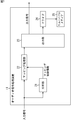
- FIG. 1 is a diagram showing a configuration example of an embodiment of an audio signal processing apparatus to which the present invention is applied.
- the audio signal processing apparatus 11 is provided in a portable reproduction apparatus that reproduces content including, for example, a video signal and an audio signal, and performs amplitude conversion so that the reproduction level is emphasized with respect to the input audio signal.
- the audio signal after amplitude conversion is output.
- an audio signal input to the audio signal processing device 11 is particularly referred to as an input signal, and an audio signal obtained by performing amplitude conversion on the input signal is referred to as an output signal.
- the audio signal processing device 11 includes an analysis unit 21, a mapping processing unit 22, an output unit 23, and a drive 24.
- the analysis unit 21 analyzes the characteristics of the supplied input signal and supplies mapping control information indicating the analysis result to the mapping processing unit 22.
- the mapping processing unit 22 performs mapping processing on the supplied input signal using the mapping control information supplied from the analyzing unit 21, and emphasizes the reproduction level of the input signal. In the mapping process, linear or nonlinear amplitude conversion is performed on the input signal. The mapping processing unit 22 supplies the output signal obtained by the mapping process to the output unit 23.
- the output unit 23 outputs the output signal supplied from the mapping processing unit 22 to a subsequent audio output unit or the like, or supplies it to the drive 24.
- the drive 24 records the output signal supplied from the output unit 23 on a removable medium 25 that is a recording medium detachably attached to the drive 24.
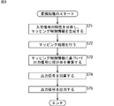
- the audio signal processing device 11 performs a conversion process when an input signal is supplied, and generates and outputs an output signal.
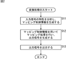
- the conversion process by the audio signal processing apparatus 11 will be described with reference to the flowchart of FIG.
- step S11 the analysis unit 21 analyzes the characteristics of the supplied input signal and generates mapping control information.
- the analysis unit 21 calculates the following equation (1) to calculate the root mean square RMS (n) for the nth sample of the input signal as mapping control information of the nth sample. .
- x (m) represents the sample value (input signal value) of the m-th sample of the input signal.
- the value of the input signal that is, the sample value of each sample of the input signal is normalized so that ⁇ 1 ⁇ x (m) ⁇ 1.
- the root mean square RMS (n) is the logarithm of the root mean square of the sample values of the samples included in the section of N consecutive samples centered on the nth sample. Is obtained by multiplying the value obtained by the constant “20”.
- the value of the root mean square RMS (n) obtained in this way is such that the smaller the absolute value of the sample value of each sample in the specific section centered on the nth sample of the input signal being processed, Get smaller. That is, the root mean square RMS (n) decreases as the sound volume of the entire specific section including the sample to be processed of the input signal decreases.
- the analysis unit 21 analyzes the input signal and obtains the mapping control information, and supplies the mapping control information to the mapping processing unit 22.
- step S12 the mapping processing unit 22 performs mapping processing on the supplied input signal using the mapping control information supplied from the analysis unit 21, and generates an output signal.
- the mapping processing unit 22 performs amplitude conversion by substituting the sample value x of the nth sample of the input signal into a non-linear mapping function f (x) represented by the following equation (2). That is, the value obtained by substituting the sample value x into the mapping function f (x) is the sample value of the nth sample of the output signal.
- the sample value x of the input signal is normalized so as to be a value from ⁇ 1 to 1.
- ⁇ represents a control factor
- this control factor ⁇ is a numerical value determined by the value of the mapping control information.
- mapping function f (x) when the sample value x is greater than or equal to ⁇ 1 and less than ⁇ 0.5, the mapping function f (x) becomes (2- ⁇ ) x ⁇ ( ⁇ 1), and the sample value x Is ⁇ 0.5 or more and 0.5 or less, the mapping function f (x) is ⁇ x. If the sample value x is greater than 0.5 and less than or equal to 1, the mapping function f (x) is (2- ⁇ ) x + ( ⁇ -1).
- control factor ⁇ is a value determined by the following equation (3).
- root mean square RMS (n) which is mapping control information
- the value of control factor ⁇ is set to (RMS (n) / ⁇ 30) +1.
- the range of values that the control factor ⁇ can take is 1 ⁇ ⁇ ⁇ 2, and the larger the root mean square RMS (n), the smaller the value of the control factor ⁇ .
- the root mean square RMS (n) value is ⁇ 30 or less, the value of the control factor ⁇ is “2”.
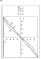
- control factor ⁇ increases as the sound volume based on the input signal decreases as a whole, that is, the root mean square RMS (n) decreases, and as a result, the mapping function f (x) as shown in FIG. The slope of becomes larger.
- the horizontal axis indicates the sample value x of the input signal
- the vertical axis indicates the value of the mapping function f (x).
- a straight line f11, a curve f12, and a curve f13 represent the mapping function f (x) when the control factor ⁇ is “1.0”, “1.4”, and “1.8”, respectively.
- mapping function f (x) which changes more steeply as the volume of the sound based on the input signal is reduced as a whole, is used to perform amplitude conversion of the input signal. That is, the smaller the volume of the sound is, the larger the change amount of f (x) with respect to the change of the sample value x in the mapping function f (x).
- the control factor ⁇ is “1.0”, and in the mapping function f (x) indicated by the straight line f11, the sample value of the input signal is directly used as the sample value of the output signal.
- the mapping function f (x) indicated by the curve f13 with the control factor ⁇ being “1.8” the mapping function f (x) is the mapping function in the interval where the sample value x of the input signal is ⁇ 0.5 or more and 0.5 or less. Is larger than the slope of the mapping function indicated by the straight line f11.
- the amplitude conversion of the input signal is performed.
- the amplitude of the input signal is converted so that the sound of low sound is converted into sound having a higher sound volume, and the playback level of the input signal is emphasized.
- content such as a movie with a large volume dynamic range is played back on a portable device incorporating a small speaker, a small sound that was difficult to hear in the past can be easily heard by mapping the input signal. Can do.
- mapping function f (x) having a moderately steep characteristic is used for a signal having a small sample value x, and the amplitude of the input signal Conversion is performed.
- the amplitude of the input signal is converted so that the low volume of the sound is converted into a high volume, and the reproduction level of the input signal is emphasized.
- the sound that has been reproduced relatively large conventionally can be heard even louder.
- the audio signal processing device 11 performs an analysis on the input signal in advance and adds additional information for amplitude conversion to the input signal, or pre-reads the input signal for a long period, and reads the input signal. There is no need to perform amplitude conversion after analysis.
- mapping function f (x) by the control factor ⁇ , it is possible to realize amplitude conversion with a higher degree of freedom.
- the mapping function is the most effective nonlinear function, so that not only the characteristics of the section containing the sample to be processed but also the sample value of that sample. Amplitude conversion in consideration of the size can be performed.
- the audio signal is multiplied by a constant determined by the average value of the absolute value of the audio signal, regardless of the value of the audio signal. That is, the sample of the audio signal is always multiplied by a constant regardless of the amplitude of the sample.
- the audio signal is multiplied by a constant for a sound with a high volume.
- the volume may not be appropriate.
- the mapping function is a non-linear function
- the amplitude is not changed greatly when the amplitude (sample value) of the sample is large, and the amplitude is changed when the amplitude of the sample is small.
- Amplitude conversion with a high degree of freedom is possible, such as a large increase. This makes it possible to effectively enhance the playback level of the audio signal, such as converting a sound with a low volume into a sound with a high volume and preventing the volume of a sound with a high volume from changing so much. .
- the dynamic range of the sound volume can be further expanded or left as it is, or the dynamic range can be narrowed by amplitude conversion.
- the audio signal processing device 11 can easily and effectively enhance the reproduction level of the audio signal.
- mapping processing unit 22 supplies the obtained output signal to the output unit 23 when the output signal is generated by the mapping process.
- step S13 the output unit 23 outputs the output signal supplied from the mapping processing unit 22 to the subsequent stage, and the conversion process ends.
- the output unit 23 supplies an output signal to the drive 24 as necessary, and the drive 24 records the supplied output signal on the removable medium 25.
- the audio signal processing device 11 analyzes the characteristics of the input signal, performs the mapping process on the input signal using the mapping function that changes according to the analysis result, and generates the output signal.
- the root mean square RMS (n) as mapping control information obtained by analyzing the input signal indicates the size of the average sample value in a predetermined section of the input signal, that is, the distribution of the amplitude of each sample in the predetermined section. .
- the input signal contains many samples with small amplitudes.
- the root mean square RMS (n) is large, the input signal contains many samples with large amplitudes. It is.
- a mapping function having a more effective characteristic is generated using the root mean square RMS (n), and the mapping process is performed, whereby the input signal easily has an ideal amplitude distribution. It can be converted into an output signal.
- mapping function the function in which each section is a straight line has been described as the mapping function.
- a smoother curve function may be used as the mapping function.
- a nonlinear function represented by the following equation (4) is used as the mapping function.
- x represents the sample value of the sample of the input signal, and the sample value x of the input signal is normalized so as to be a value from ⁇ 1 to 1. Further, the control factor ⁇ in the equation (4) is determined by the following equation (5).
- root mean square RMS (n) which is mapping control information
- the value of control factor ⁇ is (RMS (n) / ⁇ 30) ⁇ 5 + 5 Is done.
- the range of values that the control factor ⁇ can take is 5 ⁇ ⁇ ⁇ 10, and the larger the root mean square RMS (n), the smaller the value of the control factor ⁇ .
- the control factor ⁇ is set to 10.
- the horizontal axis indicates the sample value x of the input signal
- the vertical axis indicates the value of the mapping function f (x).
- Curves f21 to f23 represent the mapping function f (x) when the control factor ⁇ is “5”, “7”, and “10”, respectively.
- mapping function shown in Expression (4) and the control factor ⁇ shown in Expression (5) are used, the mapping function shown in Expression (2) and the control factor ⁇ shown in Expression (3) are used.
- mapping function of the above-described equation (4) is an exponential function
- the amount of calculation increases when the calculation of the mapping process is performed by a computer, DSP (Digital Signal Processor), or the like. Therefore, for example, if a cubic function represented by the following equation (6) is adopted as the mapping function, the amount of calculation can be reduced and the mapping process can be performed more quickly.
- x represents the sample value of the sample of the input signal, and the sample value x of the input signal is normalized to be a value from ⁇ 1 to 1. Further, the control factor ⁇ in the equation (6) is determined by the following equation (7).
- root mean square RMS (n) which is mapping control information
- the control factor ⁇ is set to “100”
- the value of root mean square RMS (n) is ⁇
- the value of the control factor ⁇ is set to ⁇ 30 / RMS (n) ⁇ 3.
- the range of values that the control factor ⁇ can take is 3 ⁇ ⁇ 100, and the value of the control factor ⁇ increases as the root mean square RMS (n) increases.
- the control factor ⁇ is set to “3.0”.
- the horizontal axis indicates the sample value x of the input signal
- the vertical axis indicates the value of the mapping function f (x).
- Curves f31 to f33 represent mapping functions f (x) when the control factor ⁇ is “100”, “5”, and “3”, respectively.
- mapping function f (x) having a larger change amount of f (x) with respect to the change of the sample value x is used as the volume of the sound based on the input signal is lower as a whole. Amplitude conversion of the input signal is performed.
- mapping function shown in Expression (6) and the control factor ⁇ shown in Expression (7) are used, the mapping function shown in Expression (2) and the control factor ⁇ shown in Expression (3) are used.
- the mapping function f (x) may be any function as long as ⁇ 1 ⁇ f (x) ⁇ 1 with respect to the sample value x satisfying ⁇ 1 ⁇ x ⁇ 1. .
- mapping control information may be other elements, Elements may be combined into mapping control information.
- a moving average value of sample values of samples in a predetermined section of the input signal, the number of zero crossings of samples in the predetermined section, a value indicating the tonality of the input signal, and the like may be used as the mapping control information.
- the mapping function, the control factor, and the mapping control information may be used as long as the processing effect is high and sound suitable for hearing can be obtained by the mapping processing.
- mapping control information and the control factor ⁇ of the mapping function are calculated for each sample of the input signal and the mapping process is performed.
- the mapping control information and the control factor are calculated for every two or more consecutive samples. ⁇ may be calculated and the mapping process may be performed. For example, in such a case, mapping control information and control factors calculated for one sample are continuously used for a predetermined number of consecutive samples.
- the enhancement method of the audio signal reproduction level may be adjusted by changing the mapping control information and the control factor calculation method according to the output destination device of the output signal.
- the relationship between the control factor ⁇ and the mapping control information may be changed, for example, by using a different expression to calculate the control factor ⁇ .
- the audio signal processing apparatus is configured as shown in FIG. 6, for example.
- FIG. 6 includes an analysis unit 21, a mapping processing unit 22, a mapping processing unit 61, an output unit 23, and a drive 24.
- FIG. 6 parts corresponding to those in FIG. 1 are denoted by the same reference numerals, and description thereof is omitted as appropriate.
- the audio signal processing device 51 is supplied with, for example, a left channel audio signal and a right channel audio signal constituting a content such as a movie as input signals. That is, the left channel input signal is supplied to the analysis unit 21 and the mapping processing unit 22, and the right channel input signal is supplied to the analysis unit 21 and the mapping processing unit 61.
- the analysis unit 21 analyzes characteristics of the supplied left and right channel input signals, generates mapping control information based on the obtained two analysis results, and performs mapping processing unit 22 and mapping processing. Supplied to the unit 61.
- the mapping processing unit 61 performs mapping processing on the supplied right channel input signal using the mapping control information supplied from the analysis unit 21, and generates a right channel output signal.
- the mapping processing unit 61 performs the same processing as the mapping processing unit 22.
- the mapping processing unit 61 supplies the output signal of the right channel obtained by the mapping processing to the output unit 23.
- mapping processing unit 22 and the mapping processing unit 61 use the common mapping control information to perform the mapping processing.
- the output unit 23 outputs the output signals of the left and right channels supplied from the mapping processing unit 22 and the mapping processing unit 61 to the subsequent stage, or supplies them to the drive 24 so as to be recorded on the removable medium 25.
- step S41 the analysis unit 21 analyzes the characteristics of the input signals of the supplied left and right channels. For example, the analysis unit 21 calculates the above-described equation (1) to calculate the root mean square RMS (n) of the left channel and the root mean square RMS (n) of the right channel.
- step S42 the analysis unit 21 generates mapping control information based on the analysis result of the characteristics of the input signal, and supplies the mapping control information to the mapping processing unit 22 and the mapping processing unit 61.
- the analysis unit 21 obtains an average value of the root mean square RMS (n) of the left channel and the root mean square RMS (n) of the right channel, and uses the obtained average value as mapping control information.
- mapping control information the larger value of the root mean square RMS (n) of the left channel and the root mean square RMS (n) of the right channel may be used as mapping control information as it is.
- a sample of the left channel input signal and a sample of the right channel input signal may be used to calculate one root mean square RMS (n) or the like as mapping control information.
- step S42 When the processing of step S42 is performed and the mapping control information is generated, then the processing of step S43 and step S44 is performed and the conversion processing is terminated, but these processing are the steps S12 and S13 of FIG. Since this is the same as the above process, the description thereof is omitted.
- mapping control information is used in the mapping processing unit 22 and the mapping processing unit 61, and a left channel output signal and a right channel output signal are generated by the same mapping function and control factor, respectively. .
- the audio signal processing device 51 analyzes the characteristics of the input signals of the left and right channels, generates common mapping control information for the left and right channels, and uses the obtained mapping control information for each channel. Execute the same mapping process. In this way, by using the same mapping control information for the left and right channels, the same mapping process is performed on the input signal of each channel, so that the playback level of the audio signal can be achieved without changing the volume balance between channels. Can be emphasized.
- the input signals of the two left and right channels are input has been described.
- the input signal may be composed of three or more channels. Even in such a case, mapping control information common to all channels is generated.
- the output signal is generated using one mapping function.
- a plurality of linear or non-linear mapping functions are prepared, and these mapping functions are selectively used according to the mapping control information.
- An output signal may be generated.
- the output of a plurality of mapping functions is weighted and added according to the mapping control information to obtain an output signal, thereby smoothly changing the output caused by switching the mapping function used for generating the output signal. can do.
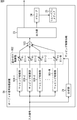
- the audio signal processing device when an output signal is generated using a plurality of mapping functions, the audio signal processing device has a configuration shown in FIG. 8, for example.
- the audio signal processing device 91 includes an analysis unit 21, mapping processing units 101-1 to 101 -M, a weighting control unit 102, an addition unit 103, an output unit 23, and a drive 24.
- an analysis unit 21 mapping processing units 101-1 to 101 -M, a weighting control unit 102, an addition unit 103, an output unit 23, and a drive 24.
- mapping processing unit 101-1 through mapping processing unit 101-M perform mapping processing on the supplied input signal using different mapping functions, and supply the resulting output signal to the weighting control unit 102. To do.
- mapping processing unit 101-1 to the mapping processing unit 101-M are also simply referred to as the mapping processing unit 101 when it is not necessary to distinguish them individually.
- the weighting control unit 102 multiplies the output signal supplied from the mapping processing unit 101 by a proration rate that is a weight determined by the mapping control information supplied from the analysis unit 21, and supplies the result to the addition unit 103. That is, the weight control unit 102 includes multiplication units 111-1 to 111-M. The multipliers 111-1 through 111 -M multiply the output signals supplied from the mapping processors 101-1 through 101 -M by proportional distribution ratios ⁇ 1 through ⁇ M determined by the mapping control information. Then, it is supplied to the adding unit 103.
- multipliers 111-1 to 111-M when it is not necessary to individually distinguish the multipliers 111-1 to 111-M, they are also simply referred to as multipliers 111.
- the adder 103 adds the M output signals supplied from the multiplier 111 and supplies the final output signal obtained as a result to the output unit 23.
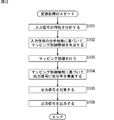
- step S71 the analysis unit 21 analyzes the characteristics of the supplied input signal and generates mapping control information.
- the analysis unit 21 performs the calculation of the above-described equation (1), calculates the root mean square RMS (n) for the n-th sample of the input signal as mapping control information, and supplies it to the weighting control unit 102 To do.
- step S72 the mapping processing unit 101 performs mapping processing on the supplied input signal, and supplies the obtained output signal to the multiplication unit 111.
- the audio signal processing device 91 is provided with four mapping processing units 101-1 to 101-4.
- the mapping processing units 101-1 to 101-4 supply the mapping functions f 1 (x) to f 4 (x) represented by the following equations (8) to (11). Mapping processing is performed on the input signal. That is, the value obtained by substituting the sample value x of the nth sample of the input signal into the mapping function is the sample value of the nth sample of the output signal.
- x indicates the sample value of the input signal sample.
- the input signal sample value x is from ⁇ 1 to 1. It is assumed that the value is normalized so that
- mapping functions f 1 (x) to f 4 (x) change more steeply in the order of the mapping functions f 4 (x) to f 1 (x), as shown in FIG. It is a function of characteristics.
- mapping functions f 1 (x) to f 4 (x) are shown in the upper left, upper right, lower left, and lower right, respectively.
- the horizontal axis indicates the sample value x of the input signal
- the vertical axis indicates the value of the mapping function.
- step S ⁇ b> 73 the weighting control unit 102 sets a distribution ratio as a weight to the output signal supplied from the mapping processing unit 101 based on the mapping control information supplied from the analysis unit 21. Multiply.
- the audio signal processing device 91 is provided with four mapping processing units 101-1 to 101-4.
- the weighting control unit 102 performs the calculation shown in the following equation (12) based on the root mean square RMS (n) as the mapping control information, and performs the mapping function f 1 (x) to the mapping function f 4 (x ) To the distribution ratio ⁇ 1 to the distribution ratio ⁇ 4 .
- ⁇ 1 at the proration rate ⁇ 2 indicates the value of the proration rate ⁇ 1 .
- 2 alpha in the distribution ratios alpha 3 shows the values of the distribution ratios alpha 2.
- ⁇ 3 in the proration rate ⁇ 4 indicates the value of the proration rate ⁇ 3 .
- the weighting control unit 102 increases the weight of the mapping function that changes more rapidly as the root mean square RMS (n) is smaller, that is, as the sound volume based on the input signal is smaller as a whole. Then, a proration rate ⁇ 1 to an apportion rate ⁇ 4 are calculated. Conversely, in a section where the root mean square RMS (n) is large and the volume of the sound based on the input signal is large, the distribution ratio is determined so that the weight of the mapping function having a more gradually changing characteristic becomes large.
- the mapping function that changes more rapidly is emphasized and the amplitude conversion of the input signal is performed.
- the multipliers 111-1 to 111-4 output the output signals supplied from the mapping processors 101-1 to 101-4. Multiplication is performed by the proration rate ⁇ 1 to the proration rate ⁇ 4, and the result is supplied to the adding unit 103.
- the proration rate to be multiplied by the output signals is calculated.
- the mapping processing is performed after the proration rate is calculated. You may do it.
- a proration rate ⁇ 1 to an apportion rate ⁇ M are obtained, and only an output signal multiplied by an apportion rate other than “0” among these apportionment rates is obtained by the mapping process. Generated. That is, the mapping processing unit 101 that uses the mapping function corresponding to the proration rate with the value “0” does not perform the mapping process for the input signal. In this way, if only the output signal multiplied by the proration rate whose value is not “0” is generated, the amount of calculation can be reduced and the final output signal can be obtained quickly.
- each distribution ratio is calculated by calculation
- a table in which the value of the mapping control information and the distribution ratio ⁇ 1 to the distribution ratio ⁇ M determined by the value are recorded in association with each other is prepared in advance.
- each distribution ratio may be obtained by table lookup.
- step S74 the adder 103 adds the output signals supplied from the multipliers 111-1 to 111-M to generate one final output signal.
- the output signal obtained using a plurality of different mapping functions is weighted and added using a proration rate, so that the amplitude conversion of the input signal using one mapping function is realized approximately. be able to. For example, if the distribution ratio ⁇ 1 and the distribution ratio ⁇ 2 are “0” and the distribution ratio ⁇ 3 and the distribution ratio ⁇ 4 are predetermined values other than “0”, the mapping function f 3 (x) and the mapping function f 4 are set. Amplitude conversion using a mapping function having characteristics between (x) can be realized.
- the audio signal processing device 91 can realize amplitude conversion with a higher degree of freedom by dynamically changing the mapping function that is approximately generated according to the characteristics of each section of the input signal. That is, by generating a mapping function approximately for each section of the input signal according to the characteristics of each section, as in the case of the audio signal processing apparatus 11, not only the characteristics of the section but also the sample to be processed is processed. Amplitude conversion can be performed in consideration of the sample value.
- mapping function it is possible to further increase the dynamic range of the sound volume by the amplitude conversion, leave it as it is, or narrow the dynamic range.
- step S74 When the process of step S74 is performed, the process of step S75 is performed thereafter, and the conversion process ends. However, the process of step S75 is the same as the process of step S13 of FIG.
- the audio signal processing device 91 performs the mapping process on the input signal using a plurality of different mapping functions, and the obtained output signals are divided into proportions obtained from the analysis results of the characteristics of the input signals. The weighted addition is performed to obtain the final output signal.
- the mapping function is selectively used to perform the mapping process, and the output signal is generated.
- the reproduction level of the audio signal can be effectively enhanced. Further, it is possible to make it easier to hear a small sound that has been difficult to hear conventionally, and to make it easier to hear a sound that has been relatively loud conventionally.
- the audio signal processing apparatus 91 also adjusts the enhancement level of the audio signal reproduction level by changing the mapping control information and the distribution ratio calculation method in accordance with the output destination device of the output signal. Good.
- mapping control information and the distribution ratio are calculated for each sample of the input signal and the output signal is generated.
- mapping control information and the distribution ratio are calculated for every two or more consecutive samples. You may do it.
- FIG. 8 illustrates the case where the input signal as the audio signal is one channel, the input signal may be a plurality of channels.
- the audio signal processing device is configured as shown in FIG.
- the audio signal processing device 141 in FIG. 11 includes an analysis unit 21, a mapping processing unit 101-1 to a mapping processing unit 101-M, a weighting control unit 102, an adding unit 103, a mapping processing unit 151-1 to a mapping processing unit 151-M. , A weighting control unit 152, an adding unit 153, an output unit 23, and a drive 24.
- FIG. 11 parts corresponding to those in FIG. 8 are denoted by the same reference numerals, and description thereof will be omitted as appropriate.
- a left channel audio signal and a right channel audio signal constituting content such as a movie are supplied to the audio signal processing device 141 as input signals. That is, the input signal of the left channel is supplied to the analysis unit 21 and the mapping processing unit 101-1 to the mapping processing unit 101-M, and the input signal of the right channel is supplied to the analysis unit 21, the mapping processing unit 151-1 to the mapping processing unit 151. -Supplied to M.
- the analysis unit 21 analyzes characteristics of the supplied left and right channel input signals, generates mapping control information based on the obtained two analysis results, and performs weighting control unit 102 and weighting control. To the unit 152.
- the mapping processing unit 151-1 to the mapping processing unit 151-M perform mapping on the supplied input signal using the same mapping function as that used by the mapping processing unit 101-1 to the mapping processing unit 101-M, respectively. Process. Also, the mapping processing unit 151-1 to the mapping processing unit 151-M supply the output signal obtained by the mapping processing to the weighting control unit 152. Hereinafter, the mapping processing unit 151-1 to the mapping processing unit 151-M are also simply referred to as the mapping processing unit 151 when it is not necessary to distinguish them individually.
- the weight control unit 152 performs the same operation as the weight control unit 102. That is, the multiplication units 161-1 to 161 -M constituting the weighting control unit 152 correspond to the multiplication units 111-1 to 111 -M, and the mapping processing unit 151-1 to the mapping processing unit 151.
- the output signal supplied from ⁇ M is multiplied by a proration rate ⁇ 1 to an apportion rate ⁇ M and supplied to the adder 153.
- multipliers 161 when it is not necessary to individually distinguish the multipliers 161-1 to 161-M, they are also simply referred to as multipliers 161.
- the addition unit 153 adds the M output signals supplied from the multiplication unit 161, and supplies the final output signal obtained as a result to the output unit 23.
- step S101 the analysis unit 21 analyzes the characteristics of the input signals of the supplied left and right channels. For example, the analysis unit 21 calculates the above-described equation (1) to calculate the root mean square RMS (n) of the left channel and the root mean square RMS (n) of the right channel.
- step S102 the analysis unit 21 generates mapping control information based on the analysis result of the characteristics of the input signal, and supplies the mapping control information to the weighting control unit 102 and the weighting control unit 152.
- the analysis unit 21 obtains an average value of the root mean square RMS (n) of the left channel and the root mean square RMS (n) of the right channel, and uses the obtained average value as mapping control information.
- step S102 When the processing of step S102 is performed and the mapping control information is generated, the processing of step S103 to step S106 is performed thereafter, and the conversion processing is terminated.
- step S103 to step S106 These processing are the steps S72 to S75 of FIG. Since this is the same as the above process, the description thereof is omitted.
- mapping processing is performed by the mapping processing unit 101, and the obtained output signal is multiplied by the proration rate by the multiplication unit 111, and the output obtained by multiplying the apportion rate by the addition unit 103 is obtained.
- the signals are added to obtain the final output signal of the left channel.
- mapping processing is performed by the mapping processing unit 151, and the obtained output signal is multiplied by the proportional division rate by the multiplication unit 161, and the output signal multiplied by the proportional distribution rate is added by the addition unit 153. This is the final output signal of the right channel.
- the audio signal processing device 141 analyzes the characteristics of the input signals of the left and right channels, generates common mapping control information for the left and right channels, and uses the obtained mapping control information for each mapping function. Calculate the distribution ratio common to the left and right channels. In this way, by using the common mapping control information for the left and right channels, and calculating the common distribution ratio for the left and right channels for each mapping function, the audio signal level can be changed without changing the volume balance between the channels. The playback level can be emphasized.
- the series of processes described above can be executed by hardware or software.
- a program constituting the software may execute various functions by installing a computer incorporated in dedicated hardware or various programs. For example, it is installed from a program recording medium in a general-purpose personal computer or the like.
- FIG. 13 is a block diagram illustrating a configuration example of hardware of a computer that executes the above-described series of processes by a program.
- a CPU Central Processing Unit
- ROM Read Only Memory
- RAM Random Access Memory
- An input / output interface 205 is further connected to the bus 204.
- the input / output interface 205 includes an input unit 206 including a keyboard, a mouse, and a microphone, an output unit 207 including a display and a speaker, a recording unit 208 including a hard disk and nonvolatile memory, and a communication unit 209 including a network interface.
- a drive 210 for driving a removable medium 211 such as a magnetic disk, an optical disk, a magneto-optical disk, or a semiconductor memory is connected.
- the CPU 201 loads, for example, the program recorded in the recording unit 208 to the RAM 203 via the input / output interface 205 and the bus 204, and executes the program. Is performed.
- Programs executed by the computer (CPU 201) are, for example, a magnetic disk (including a flexible disk), an optical disk (CD-ROM (Compact Disc-Read Only Memory), DVD (Digital Versatile Disc), etc.), a magneto-optical disk, or a semiconductor.
- the program is recorded on a removable medium 211 that is a package medium including a memory or the like, or provided via a wired or wireless transmission medium such as a local area network, the Internet, or digital satellite broadcasting.
- the program can be installed in the recording unit 208 via the input / output interface 205 by attaching the removable medium 211 to the drive 210.
- the program can be received by the communication unit 209 via a wired or wireless transmission medium and installed in the recording unit 208.
- the program can be installed in the ROM 202 or the recording unit 208 in advance.
- the program executed by the computer may be a program that is processed in time series in the order described in this specification, or in parallel or at a necessary timing such as when a call is made. It may be a program for processing.
- 11 Audio signal processing device 21 analysis unit, 22 mapping processing unit, 61 mapping processing unit, 101-1 to 101-M, 101 mapping processing unit, 102 weighting control unit, 103 addition unit, 151-1 to 151-M, 151 Mapping processing unit, 152 weighting control unit, 153 addition unit
Landscapes
- Engineering & Computer Science (AREA)
- Multimedia (AREA)
- Stereophonic System (AREA)
- Signal Processing For Digital Recording And Reproducing (AREA)
- Tone Control, Compression And Expansion, Limiting Amplitude (AREA)
- Complex Calculations (AREA)
Abstract
Description
[オーディオ信号処理装置の構成]
図1は、本発明を適用したオーディオ信号処理装置の一実施の形態の構成例を示す図である。
次に、図1のオーディオ信号処理装置11の動作について説明する。



なお、以上においては、各区間が直線となる関数をマッピング関数として用いると説明したが、より滑らかな曲線の関数がマッピング関数として用いられてもよい。そのような場合、例えば、次式(4)に示される非線形関数がマッピング関数とされる。


また、上述した式(4)のマッピング関数は指数関数であるため、コンピュータやDSP(Digital Signal Processor)等でマッピング処理の演算を行なうと、一般的に演算量が大きくなってしまう。そこで、例えば次式(6)に示す3次関数をマッピング関数として採用すれば、演算量を少なくし、より迅速にマッピング処理を行うことができるようになる。


[オーディオ信号処理装置の構成]
ところで、オーディオ信号である入力信号のチャンネル数が2以上である場合、チャンネルごとに独立して入力信号の特性の分析やマッピング処理を行うと、出力信号に基づく音声のチャンネル間の音量のバランスが変化してしまうことがある。
次に、図7のフローチャートを参照して、オーディオ信号処理装置51による変換処理について説明する。
[オーディオ信号処理装置の構成]
また、以上においては、1つのマッピング関数を用いて出力信号を生成すると説明したが、線形または非線形のマッピング関数を複数用意し、マッピング制御情報に応じて、それらのマッピング関数を選択的に用いて出力信号を生成するようにしてもよい。そのような場合、例えば、マッピング制御情報に応じて、複数のマッピング関数の出力を重み付け加算して出力信号とすることで、出力信号の生成に用いるマッピング関数の切り替えにより生じる出力の変化を滑らかにすることができる。
次に、図9のフローチャートを参照して、オーディオ信号処理装置91による変換処理について説明する。


[オーディオ信号処理装置の構成]
また、図8では、オーディオ信号としての入力信号が1チャンネルの場合について説明したが、入力信号が複数チャンネルとされてもよい。例えば、2つのチャンネルの入力信号が入力される場合、オーディオ信号処理装置は、図11に示す構成とされる。
次に、図12のフローチャートを参照して、オーディオ信号処理装置141による変換処理について説明する。
Claims (18)
- 入力信号の特性を分析する分析手段と、
予め定められた線形関数または非線形関数に基づいて、前記入力信号を振幅変換するマッピング処理手段と、
複数の前記マッピング処理手段のそれぞれにより、互いに異なる関数に基づいて振幅変換された複数の前記入力信号のそれぞれに対して、前記入力信号の特性の分析結果により定まる重みを乗算する重み付け制御手段と、
前記重みが乗算された複数の前記入力信号を加算して出力信号を生成する加算手段と
を備える信号処理装置。 - 前記分析手段は、前記入力信号の所定区間に含まれるサンプルの平均的なサンプル値を示す値を前記分析結果として算出する
請求項1に記載の信号処理装置。 - 前記分析結果は、前記所定区間に含まれるサンプルのサンプル値の二乗平均平方根または移動平均値である
請求項2に記載の信号処理装置。 - 前記分析手段は、複数のチャンネルごとに前記入力信号に対する振幅変換が行なわれて、各チャンネルの前記出力信号が生成される場合、前記複数のチャンネルの前記入力信号に基づいて、全チャンネルで共通する1つの前記分析結果を算出する
請求項1に記載の信号処理装置。 - 前記重みは、前記入力信号の1サンプルごとに前記分析結果により定められる
請求項1に記載の信号処理装置。 - 前記重みは、前記入力信号の2以上である所定数の連続するサンプルごとに前記分析結果により定められる
請求項1に記載の信号処理装置。 - 入力信号の特性を分析する分析手段と、
予め定められた線形関数または非線形関数に基づいて、前記入力信号を振幅変換するマッピング処理手段と、
複数の前記マッピング処理手段のそれぞれにより、互いに異なる関数に基づいて振幅変換された複数の前記入力信号のそれぞれに対して、前記入力信号の特性の分析結果により定まる重みを乗算する重み付け制御手段と、
前記重みが乗算された複数の前記入力信号を加算して出力信号を生成する加算手段と
を備える信号処理装置の信号処理方法であって、
前記分析手段が、前記入力信号の特性を分析し、
複数の前記マッピング処理手段が、前記入力信号を振幅変換し、
前記重み付け制御手段が、前記分析結果により定まる前記重みを、振幅変換された前記入力信号に乗算し、
前記加算手段が、前記重みが乗算された前記入力信号を加算して前記出力信号を生成する
ステップを含む信号処理方法。 - 入力信号の特性を分析し、
予め定められた線形関数または非線形関数に基づいて、前記入力信号を振幅変換し、
互いに異なる複数の関数に基づいて振幅変換された複数の前記入力信号のそれぞれに対して、前記入力信号の特性の分析結果により定まる重みを乗算し、
前記重みが乗算された複数の前記入力信号を加算して出力信号を生成する
ステップを含む処理をコンピュータに実行させるプログラム。 - 入力信号の特性を分析し、
予め定められた線形関数または非線形関数に基づいて、前記入力信号を振幅変換し、
互いに異なる複数の関数に基づいて振幅変換された複数の前記入力信号のそれぞれに対して、前記入力信号の特性の分析結果により定まる重みを乗算し、
前記重みが乗算された複数の前記入力信号を加算する
ことで得られた出力信号が記録されたデータ記録媒体。 - 入力信号の特性を分析する分析手段と、
前記入力信号の特性の分析結果により定まる非線形関数に基づいて、前記入力信号を振幅変換し、出力信号を生成するマッピング処理手段と
を備える信号処理装置。 - 前記分析手段は、前記入力信号の所定区間に含まれるサンプルの平均的なサンプル値を示す値を前記分析結果として算出する
請求項10に記載の信号処理装置。 - 前記分析結果は、前記所定区間に含まれるサンプルのサンプル値の二乗平均平方根または移動平均値である
請求項11に記載の信号処理装置。 - 前記分析手段は、複数のチャンネルごとに前記入力信号に対する振幅変換が行なわれて、各チャンネルの前記出力信号が生成される場合、前記複数のチャンネルの前記入力信号に基づいて、全チャンネルで共通する1つの前記分析結果を算出する
請求項10に記載の信号処理装置。 - 前記非線形関数は、前記入力信号の1サンプルごとに前記分析結果により定められる
請求項10に記載の信号処理装置。 - 前記非線形関数は、前記入力信号の2以上である所定数の連続するサンプルごとに前記分析結果により定められる
請求項10に記載の信号処理装置。 - 入力信号の特性を分析する分析手段と、
前記入力信号の特性の分析結果により定まる非線形関数に基づいて、前記入力信号を振幅変換し、出力信号を生成するマッピング処理手段と
を備える信号処理装置の信号処理方法であって、
前記分析手段が、前記入力信号の特性を分析し、
前記マッピング処理手段が、前記非線形関数に基づいて、前記入力信号を振幅変換する ステップを含む信号処理方法。 - 入力信号の特性を分析し、
前記入力信号の特性の分析結果により定まる非線形関数に基づいて、前記入力信号を振幅変換し、出力信号を生成する
ステップを含む処理をコンピュータに実行させるプログラム。 - 入力信号の特性を分析し、
前記入力信号の特性の分析結果により定まる非線形関数に基づいて、前記入力信号を振幅変換する
ことで得られた出力信号が記録されたデータ記録媒体。
Priority Applications (9)
| Application Number | Priority Date | Filing Date | Title |
|---|---|---|---|
| US13/505,443 US8903098B2 (en) | 2010-09-08 | 2011-09-06 | Signal processing apparatus and method, program, and data recording medium |
| AU2011299934A AU2011299934A1 (en) | 2010-09-08 | 2011-09-06 | Signal processing device and method, program, and data recording medium |
| BR112012010517A BR112012010517A2 (pt) | 2010-09-08 | 2011-09-06 | aparelho e método de processamento de sinal, programa. e, meio de gravação de dados |
| CN2011800044042A CN102598505A (zh) | 2010-09-08 | 2011-09-06 | 信号处理装置和方法、程序以及数据记录介质 |
| RU2012117806/08A RU2012117806A (ru) | 2010-09-08 | 2011-09-06 | Устройство и способ обработки сигналов, программа и носитель информации |
| MX2012005074A MX2012005074A (es) | 2010-09-08 | 2011-09-06 | Dispositivo y metodo de procesamiento de señal, programa y medio de grabacion de datos. |
| EP11823574.6A EP2615736B1 (en) | 2010-09-08 | 2011-09-06 | Signal processing device and method, program, and data recording medium |
| CA2778776A CA2778776A1 (en) | 2010-09-08 | 2011-09-06 | Signal processing apparatus and method, program, and data recording medium |
| US14/528,205 US9584081B2 (en) | 2010-09-08 | 2014-10-30 | Signal processing apparatus and method, program, and data recording medium |
Applications Claiming Priority (2)
| Application Number | Priority Date | Filing Date | Title |
|---|---|---|---|
| JP2010-201078 | 2010-09-08 | ||
| JP2010201078A JP5903758B2 (ja) | 2010-09-08 | 2010-09-08 | 信号処理装置および方法、プログラム、並びにデータ記録媒体 |
Related Child Applications (2)
| Application Number | Title | Priority Date | Filing Date |
|---|---|---|---|
| US13/505,443 A-371-Of-International US8903098B2 (en) | 2010-09-08 | 2011-09-06 | Signal processing apparatus and method, program, and data recording medium |
| US14/528,205 Continuation US9584081B2 (en) | 2010-09-08 | 2014-10-30 | Signal processing apparatus and method, program, and data recording medium |
Publications (1)
| Publication Number | Publication Date |
|---|---|
| WO2012033099A1 true WO2012033099A1 (ja) | 2012-03-15 |
Family
ID=45810697
Family Applications (1)
| Application Number | Title | Priority Date | Filing Date |
|---|---|---|---|
| PCT/JP2011/070283 Ceased WO2012033099A1 (ja) | 2010-09-08 | 2011-09-06 | 信号処理装置および方法、プログラム、並びにデータ記録媒体 |
Country Status (10)
| Country | Link |
|---|---|
| US (2) | US8903098B2 (ja) |
| EP (1) | EP2615736B1 (ja) |
| JP (1) | JP5903758B2 (ja) |
| CN (1) | CN102598505A (ja) |
| AU (1) | AU2011299934A1 (ja) |
| BR (1) | BR112012010517A2 (ja) |
| CA (1) | CA2778776A1 (ja) |
| MX (1) | MX2012005074A (ja) |
| RU (1) | RU2012117806A (ja) |
| WO (1) | WO2012033099A1 (ja) |
Families Citing this family (22)
| Publication number | Priority date | Publication date | Assignee | Title |
|---|---|---|---|---|
| CA2581810C (en) | 2004-10-26 | 2013-12-17 | Dolby Laboratories Licensing Corporation | Calculating and adjusting the perceived loudness and/or the perceived spectral balance of an audio signal |
| TWI529703B (zh) | 2010-02-11 | 2016-04-11 | 杜比實驗室特許公司 | 用以非破壞地正常化可攜式裝置中音訊訊號響度之系統及方法 |
| JP5903758B2 (ja) * | 2010-09-08 | 2016-04-13 | ソニー株式会社 | 信号処理装置および方法、プログラム、並びにデータ記録媒体 |
| TWI581250B (zh) | 2010-12-03 | 2017-05-01 | 杜比實驗室特許公司 | 利用多媒體處理節點之適應性處理技術 |
| CN103325380B (zh) | 2012-03-23 | 2017-09-12 | 杜比实验室特许公司 | 用于信号增强的增益后处理 |
| US9588134B2 (en) * | 2012-05-10 | 2017-03-07 | Infineon Technologies Ag | Increased dynamic range sensor |
| ES3064789T3 (en) | 2012-05-18 | 2026-04-29 | Dolby Laboratories Licensing Corp | System and method for dynamic range control of an audio signal |
| US10844689B1 (en) | 2019-12-19 | 2020-11-24 | Saudi Arabian Oil Company | Downhole ultrasonic actuator system for mitigating lost circulation |
| ITTO20120530A1 (it) * | 2012-06-19 | 2013-12-20 | Inst Rundfunktechnik Gmbh | Dynamikkompressor |
| MX343571B (es) | 2013-01-21 | 2016-11-09 | Dolby Laboratories Licensing Corp | Codificador y decodificador de audio con metadatos de limite y sonoridad de programa. |
| BR112015017064B1 (pt) | 2013-01-21 | 2022-03-22 | Dolby Laboratories Licensing Corporation | Método, meio legível em computador e aparelho para otimizar o nível de intensidade do som e a faixa dinâmica através de dispositivos de reprodução diferentes |
| US9715880B2 (en) | 2013-02-21 | 2017-07-25 | Dolby International Ab | Methods for parametric multi-channel encoding |
| CN107093991B (zh) | 2013-03-26 | 2020-10-09 | 杜比实验室特许公司 | 基于目标响度的响度归一化方法和设备 |
| EP2981910A1 (en) | 2013-04-05 | 2016-02-10 | Dolby Laboratories Licensing Corporation | Acquisition, recovery, and matching of unique information from file-based media for automated file detection |
| TWM487509U (zh) | 2013-06-19 | 2014-10-01 | 杜比實驗室特許公司 | 音訊處理設備及電子裝置 |
| JP2015050685A (ja) * | 2013-09-03 | 2015-03-16 | ソニー株式会社 | オーディオ信号処理装置および方法、並びにプログラム |
| WO2015038522A1 (en) | 2013-09-12 | 2015-03-19 | Dolby Laboratories Licensing Corporation | Loudness adjustment for downmixed audio content |
| EP4683219A3 (en) | 2013-09-12 | 2026-03-25 | Dolby Laboratories Licensing Corporation | Dynamic range control for a wide variety of playback environments |
| CN105142067B (zh) | 2014-05-26 | 2020-01-07 | 杜比实验室特许公司 | 音频信号响度控制 |
| JP6314662B2 (ja) * | 2014-05-29 | 2018-04-25 | オンキヨー株式会社 | 音声信号処理装置およびそのプログラム |
| CN118553253A (zh) | 2014-10-10 | 2024-08-27 | 杜比实验室特许公司 | 基于发送无关的表示的节目响度 |
| US10461712B1 (en) * | 2017-09-25 | 2019-10-29 | Amazon Technologies, Inc. | Automatic volume leveling |
Citations (4)
| Publication number | Priority date | Publication date | Assignee | Title |
|---|---|---|---|---|
| JPH05234249A (ja) * | 1992-02-26 | 1993-09-10 | Pioneer Electron Corp | オーディオ信号処理装置 |
| JPH05275950A (ja) | 1992-03-27 | 1993-10-22 | Matsushita Electric Ind Co Ltd | 音響信号ダイナミックレンジ圧縮装置 |
| JP2002504279A (ja) * | 1997-06-06 | 2002-02-05 | オーディオロジック ヒアリング システムズ エル.ピー. | 連続周波数ダイナミックレンジ・オーディオ・コンプレッサ |
| JP2007067868A (ja) * | 2005-08-31 | 2007-03-15 | Victor Co Of Japan Ltd | 低音増幅デジタル信号処理装置 |
Family Cites Families (52)
| Publication number | Priority date | Publication date | Assignee | Title |
|---|---|---|---|---|
| JPS5839422B2 (ja) * | 1978-07-27 | 1983-08-30 | ケイディディ株式会社 | 標本化関数形等化器 |
| US4991218A (en) * | 1988-01-07 | 1991-02-05 | Yield Securities, Inc. | Digital signal processor for providing timbral change in arbitrary audio and dynamically controlled stored digital audio signals |
| EP0345365B1 (de) * | 1988-06-07 | 1993-12-29 | Deutsche ITT Industries GmbH | Digitale Deemphasisschaltung |
| JP3227743B2 (ja) * | 1991-10-30 | 2001-11-12 | ヤマハ株式会社 | 倍音付与回路 |
| JPH07131270A (ja) * | 1993-11-05 | 1995-05-19 | Tamura Seisakusho Co Ltd | 音声制御装置 |
| JPH07288899A (ja) * | 1994-04-15 | 1995-10-31 | Matsushita Electric Ind Co Ltd | 音場再生装置 |
| US5727068A (en) * | 1996-03-01 | 1998-03-10 | Cinema Group, Ltd. | Matrix decoding method and apparatus |
| GB9616755D0 (en) * | 1996-08-09 | 1996-09-25 | Kemp Michael J | Audio effects synthesizer with or without analyser |
| US5898340A (en) * | 1996-11-20 | 1999-04-27 | Chatterjee; Manjirnath A. | High power efficiency audio amplifier with digital audio and volume inputs |
| US6044341A (en) * | 1997-07-16 | 2000-03-28 | Olympus Optical Co., Ltd. | Noise suppression apparatus and recording medium recording processing program for performing noise removal from voice |
| FR2766992B1 (fr) * | 1997-08-01 | 2000-12-29 | France Telecom | Procede de simulation d'amplificateur non lineaire a memoire d'enveloppe |
| US6058076A (en) * | 1997-12-08 | 2000-05-02 | Komninos; Nikolaos I. | Signal detector and method for detecting signals having selected frequency characteristics |
| ATE358872T1 (de) * | 1999-01-07 | 2007-04-15 | Tellabs Operations Inc | Verfahren und vorrichtung zur adaptiven rauschunterdrückung |
| US6965676B1 (en) * | 1999-10-19 | 2005-11-15 | Texas Instruments Incorporated | Volume-responsive loudness compensation circuits, systems, and methods |
| US20020131611A1 (en) * | 2001-03-13 | 2002-09-19 | Hoover Alan Anderson | `Audio surround sound power management switching |
| CA2341834C (en) * | 2001-03-21 | 2010-10-26 | Unitron Industries Ltd. | Apparatus and method for adaptive signal characterization and noise reduction in hearing aids and other audio devices |
| DE60209161T2 (de) * | 2001-04-18 | 2006-10-05 | Gennum Corp., Burlington | Mehrkanal Hörgerät mit Übertragungsmöglichkeiten zwischen den Kanälen |
| JP3457293B2 (ja) * | 2001-06-06 | 2003-10-14 | 三菱電機株式会社 | 雑音抑圧装置及び雑音抑圧方法 |
| TW200303001A (en) * | 2001-11-09 | 2003-08-16 | Sharp Kk | Liquid crystal display device |
| WO2003063346A2 (en) * | 2002-01-24 | 2003-07-31 | Koninklijke Philips Electronics N.V. | A method for decreasing the dynamic range of a signal and electronic circuit |
| JP4024557B2 (ja) * | 2002-02-28 | 2007-12-19 | 株式会社半導体エネルギー研究所 | 発光装置、電子機器 |
| JP4296753B2 (ja) * | 2002-05-20 | 2009-07-15 | ソニー株式会社 | 音響信号符号化方法及び装置、音響信号復号方法及び装置、並びにプログラム及び記録媒体 |
| DE60326484D1 (de) * | 2002-11-12 | 2009-04-16 | Koninkl Philips Electronics Nv | Verfahren und vorrichtung zur generierung von audiokomponenten |
| JP2004288046A (ja) * | 2003-03-24 | 2004-10-14 | Fuji Photo Film Co Ltd | 画像処理方法および装置並びにプログラム |
| JP4216107B2 (ja) * | 2003-03-31 | 2009-01-28 | Kddi株式会社 | アダプティブアレーアンテナシステムおよび重み係数算出制御方法 |
| US7336732B1 (en) * | 2004-07-28 | 2008-02-26 | L-3 Communications Titan Corporation | Carrier frequency detection for signal acquisition |
| JP2005129221A (ja) * | 2004-11-29 | 2005-05-19 | Fujitsu Ten Ltd | 出力レベル調整装置 |
| JP4896449B2 (ja) * | 2005-06-29 | 2012-03-14 | 株式会社東芝 | 音響信号処理方法、装置及びプログラム |
| JP2009500657A (ja) * | 2005-06-30 | 2009-01-08 | エルジー エレクトロニクス インコーポレイティド | オーディオ信号をエンコーディング及びデコーディングするための装置とその方法 |
| CN101258773A (zh) * | 2005-09-01 | 2008-09-03 | 唯听助听器公司 | 控制助听器中带分离压缩器的方法和设备 |
| TWI344751B (en) * | 2006-07-07 | 2011-07-01 | Yamaha Corp | Automatic gain control circuit |
| WO2008032828A1 (en) * | 2006-09-15 | 2008-03-20 | Panasonic Corporation | Audio encoding device and audio encoding method |
| EP2080419A1 (en) * | 2006-10-31 | 2009-07-22 | Koninklijke Philips Electronics N.V. | Control of light in response to an audio signal |
| CN101553867B (zh) * | 2006-12-07 | 2013-04-17 | Lg电子株式会社 | 用于处理音频信号的方法和装置 |
| US8335685B2 (en) * | 2006-12-22 | 2012-12-18 | Qnx Software Systems Limited | Ambient noise compensation system robust to high excitation noise |
| JP5455647B2 (ja) * | 2007-01-10 | 2014-03-26 | コーニンクレッカ フィリップス エヌ ヴェ | オーディオデコーダ |
| EP1968205A1 (en) * | 2007-02-28 | 2008-09-10 | Nederlandse Organisatie voor toegepast- natuurwetenschappelijk onderzoek TNO | Signal quality determination in cable networks |
| DE102007033877B3 (de) * | 2007-07-20 | 2009-02-05 | Siemens Audiologische Technik Gmbh | Verfahren zur Signalverarbeitung in einer Hörhilfe |
| CN101355829B (zh) * | 2007-07-25 | 2013-08-21 | 鹏智科技(深圳)有限公司 | 减小噪音影响的发声设备测试装置及测试方法 |
| JP5345067B2 (ja) * | 2007-10-30 | 2013-11-20 | クラリオン株式会社 | 聴覚感度補正装置 |
| GB2455742B (en) * | 2007-12-19 | 2011-11-02 | Wolfson Microelectronics Plc | Dynamic range controller |
| WO2009086174A1 (en) * | 2007-12-21 | 2009-07-09 | Srs Labs, Inc. | System for adjusting perceived loudness of audio signals |
| CN102077609B (zh) * | 2008-07-11 | 2015-11-25 | 歌乐株式会社 | 声学处理装置 |
| US8085952B2 (en) * | 2008-11-22 | 2011-12-27 | Mao-Liang Liu | Combination equalizer and calibrator circuit assembly for audio system |
| TWI503816B (zh) * | 2009-05-06 | 2015-10-11 | Dolby Lab Licensing Corp | 調整音訊信號響度並使其具有感知頻譜平衡保持效果之技術 |
| JP5365363B2 (ja) * | 2009-06-23 | 2013-12-11 | ソニー株式会社 | 音響信号処理システム、音響信号復号装置、これらにおける処理方法およびプログラム |
| US8660676B2 (en) * | 2009-10-16 | 2014-02-25 | Microsoft Corporation | Mitigating the impact of nonlinear echos by dynamic range compression |
| US8699720B2 (en) * | 2010-02-18 | 2014-04-15 | Walter Ka Wai Chu | Headphones with distortion-free loudness limiting and dynamic equalization device |
| US9167339B2 (en) * | 2010-07-07 | 2015-10-20 | Iii Holdings 4, Llc | Hearing damage limiting headphones |
| JP5903758B2 (ja) * | 2010-09-08 | 2016-04-13 | ソニー株式会社 | 信号処理装置および方法、プログラム、並びにデータ記録媒体 |
| JP2012235310A (ja) * | 2011-04-28 | 2012-11-29 | Sony Corp | 信号処理装置および方法、プログラム、並びにデータ記録媒体 |
| JP2013102411A (ja) * | 2011-10-14 | 2013-05-23 | Sony Corp | 音声信号処理装置、および音声信号処理方法、並びにプログラム |
-
2010
- 2010-09-08 JP JP2010201078A patent/JP5903758B2/ja not_active Expired - Fee Related
-
2011
- 2011-09-06 CA CA2778776A patent/CA2778776A1/en not_active Abandoned
- 2011-09-06 BR BR112012010517A patent/BR112012010517A2/pt not_active IP Right Cessation
- 2011-09-06 EP EP11823574.6A patent/EP2615736B1/en not_active Not-in-force
- 2011-09-06 WO PCT/JP2011/070283 patent/WO2012033099A1/ja not_active Ceased
- 2011-09-06 US US13/505,443 patent/US8903098B2/en not_active Expired - Fee Related
- 2011-09-06 RU RU2012117806/08A patent/RU2012117806A/ru not_active Application Discontinuation
- 2011-09-06 MX MX2012005074A patent/MX2012005074A/es active IP Right Grant
- 2011-09-06 CN CN2011800044042A patent/CN102598505A/zh active Pending
- 2011-09-06 AU AU2011299934A patent/AU2011299934A1/en not_active Abandoned
-
2014
- 2014-10-30 US US14/528,205 patent/US9584081B2/en not_active Expired - Fee Related
Patent Citations (4)
| Publication number | Priority date | Publication date | Assignee | Title |
|---|---|---|---|---|
| JPH05234249A (ja) * | 1992-02-26 | 1993-09-10 | Pioneer Electron Corp | オーディオ信号処理装置 |
| JPH05275950A (ja) | 1992-03-27 | 1993-10-22 | Matsushita Electric Ind Co Ltd | 音響信号ダイナミックレンジ圧縮装置 |
| JP2002504279A (ja) * | 1997-06-06 | 2002-02-05 | オーディオロジック ヒアリング システムズ エル.ピー. | 連続周波数ダイナミックレンジ・オーディオ・コンプレッサ |
| JP2007067868A (ja) * | 2005-08-31 | 2007-03-15 | Victor Co Of Japan Ltd | 低音増幅デジタル信号処理装置 |
Also Published As
| Publication number | Publication date |
|---|---|
| CA2778776A1 (en) | 2012-03-15 |
| RU2012117806A (ru) | 2013-11-10 |
| JP2012060379A (ja) | 2012-03-22 |
| CN102598505A (zh) | 2012-07-18 |
| JP5903758B2 (ja) | 2016-04-13 |
| MX2012005074A (es) | 2012-06-12 |
| US20150049874A1 (en) | 2015-02-19 |
| US20130156206A1 (en) | 2013-06-20 |
| EP2615736A1 (en) | 2013-07-17 |
| EP2615736B1 (en) | 2018-08-08 |
| BR112012010517A2 (pt) | 2017-12-05 |
| US9584081B2 (en) | 2017-02-28 |
| US8903098B2 (en) | 2014-12-02 |
| EP2615736A4 (en) | 2016-02-10 |
| AU2011299934A1 (en) | 2012-05-10 |
Similar Documents
| Publication | Publication Date | Title |
|---|---|---|
| JP5903758B2 (ja) | 信号処理装置および方法、プログラム、並びにデータ記録媒体 | |
| JP2012235310A (ja) | 信号処理装置および方法、プログラム、並びにデータ記録媒体 | |
| CN104012001B (zh) | 低音增强系统 | |
| CN102149034B (zh) | 声音增强设备及方法 | |
| CN102668374B (zh) | 音频录音的自适应动态范围增强 | |
| US20110002467A1 (en) | Dynamic enhancement of audio signals | |
| JP5012995B2 (ja) | オーディオ信号処理装置及びオーディオ信号処理方法 | |
| US9413316B2 (en) | Asymmetric polynomial psychoacoustic bass enhancement | |
| JP2015050685A (ja) | オーディオ信号処理装置および方法、並びにプログラム | |
| KR20120052999A (ko) | 스피커의 인지성 소리 강도를 증가시키는 시스템 | |
| JP2013102411A (ja) | 音声信号処理装置、および音声信号処理方法、並びにプログラム | |
| JP4747835B2 (ja) | オーディオ再生の効果付加方法およびその装置 | |
| JP5459556B2 (ja) | 音響特性調整装置、音響特性調整方法およびコンピュータプログラム | |
| JP5911852B2 (ja) | 可変指数平均検出器およびダイナミックレンジ制御器 | |
| US20050147262A1 (en) | Method for decreasing the dynamic range of a signal and electronic circuit | |
| JP5375861B2 (ja) | オーディオ再生の効果付加方法およびその装置 | |
| JP4706666B2 (ja) | 音量制御装置及びコンピュータプログラム | |
| WO2020157888A1 (ja) | 周波数帯域拡張装置、周波数帯域拡張方法、及び周波数帯域拡張プログラム | |
| JP4739887B2 (ja) | オーディオ再生装置 | |
| US20090232321A1 (en) | Acoustic signal processing apparatus, acoustic signal processing method, acoustic signal processing program, and computer readable recording medium | |
| CN122054048A (zh) | 一种音频处理方法及相关装置 | |
| CN120148544A (zh) | 一种音频信号的处理方法以及处理装置 |
Legal Events
| Date | Code | Title | Description |
|---|---|---|---|
| WWE | Wipo information: entry into national phase |
Ref document number: 201180004404.2 Country of ref document: CN |
|
| WWE | Wipo information: entry into national phase |
Ref document number: 2011299934 Country of ref document: AU |
|
| WWE | Wipo information: entry into national phase |
Ref document number: 2778776 Country of ref document: CA |
|
| WWE | Wipo information: entry into national phase |
Ref document number: 2012117806 Country of ref document: RU |
|
| WWE | Wipo information: entry into national phase |
Ref document number: MX/A/2012/005074 Country of ref document: MX |
|
| WWE | Wipo information: entry into national phase |
Ref document number: 13505443 Country of ref document: US Ref document number: 2011823574 Country of ref document: EP |
|
| 121 | Ep: the epo has been informed by wipo that ep was designated in this application |
Ref document number: 11823574 Country of ref document: EP Kind code of ref document: A1 |
|
| ENP | Entry into the national phase |
Ref document number: 2011299934 Country of ref document: AU Date of ref document: 20110906 Kind code of ref document: A |
|
| NENP | Non-entry into the national phase |
Ref country code: DE |
|
| REG | Reference to national code |
Ref country code: BR Ref legal event code: B01A Ref document number: 112012010517 Country of ref document: BR |
|
| ENP | Entry into the national phase |
Ref document number: 112012010517 Country of ref document: BR Kind code of ref document: A2 Effective date: 20120503 |