WO2012033341A2 - Microréfractomètre utilisant l'imagerie défocalisante - Google Patents
Microréfractomètre utilisant l'imagerie défocalisante Download PDFInfo
- Publication number
- WO2012033341A2 WO2012033341A2 PCT/KR2011/006620 KR2011006620W WO2012033341A2 WO 2012033341 A2 WO2012033341 A2 WO 2012033341A2 KR 2011006620 W KR2011006620 W KR 2011006620W WO 2012033341 A2 WO2012033341 A2 WO 2012033341A2
- Authority
- WO
- WIPO (PCT)
- Prior art keywords
- microfluid
- refractometer
- refractive index
- target
- measured
- Prior art date
- Legal status (The legal status is an assumption and is not a legal conclusion. Google has not performed a legal analysis and makes no representation as to the accuracy of the status listed.)
- Ceased
Links
Images




Classifications
-
- G—PHYSICS
- G01—MEASURING; TESTING
- G01N—INVESTIGATING OR ANALYSING MATERIALS BY DETERMINING THEIR CHEMICAL OR PHYSICAL PROPERTIES
- G01N21/00—Investigating or analysing materials by the use of optical means, i.e. using sub-millimetre waves, infrared, visible or ultraviolet light
- G01N21/17—Systems in which incident light is modified in accordance with the properties of the material investigated
- G01N21/41—Refractivity; Phase-affecting properties, e.g. optical path length
- G01N21/4133—Refractometers, e.g. differential
-
- G—PHYSICS
- G01—MEASURING; TESTING
- G01N—INVESTIGATING OR ANALYSING MATERIALS BY DETERMINING THEIR CHEMICAL OR PHYSICAL PROPERTIES
- G01N21/00—Investigating or analysing materials by the use of optical means, i.e. using sub-millimetre waves, infrared, visible or ultraviolet light
- G01N21/17—Systems in which incident light is modified in accordance with the properties of the material investigated
- G01N21/25—Colour; Spectral properties, i.e. comparison of effect of material on the light at two or more different wavelengths or wavelength bands
- G01N21/27—Colour; Spectral properties, i.e. comparison of effect of material on the light at two or more different wavelengths or wavelength bands using photo-electric detection ; circuits for computing concentration
- G01N21/274—Calibration, base line adjustment, drift correction
Definitions
- the present invention relates to a microrefractometer using out of focus imaging. More specifically, the present invention uses the size of the diameter of the circumscribed circle connecting the multiple out-of-focus images by forming multiple images out of focus in the image plane by using an aperture for separating the optical path of the light source.
- a technique for measuring the refractive index of a fluid micro-fluidic).
- the refractive index is the inherent property of a material measured in an optical manner.
- the refractive index is mainly used to infer the properties of the fluid in biochemistry and biomedicine because the refractive index is greatly influenced by the content of the solute in the solvent.
- Refractometers for measuring the refractive index of such microfluidics have been variously studied. However, these microrefractometers have limitations in measuring accurate refractive indices for a small amount of the fluid to be measured.
- microfluidic refractometer capable of self-correction, simple system structure, and easy and accurate refractive index measurement.
- the present invention provides a microrefractometer capable of measuring the refractive index of a microfluid from the size of a circumscribed circle connected to out-of-focused images using out-of-focus imaging.
- the present invention can accurately measure the refractive index of the microfluid by simultaneously imaging the out-of-focus image of the measurement target microfluid and the reference fluid known in advance in order to achieve self-correction when measuring the refractive index of the microfluid It is a second technical problem to provide a fine refractometer.
- a refractometer for measuring a refractive index of a microfluid includes a target in which the microfluid to be measured is positioned, an objective lens receiving light emitted from a light source and passing through the target, and the And an aperture having a plurality of pinholes for splitting an optical path of light incident on the objective lens to form an out-of-focus image on the image plane of the refractometer.
- the target may preferably include a measurement region in which the microfluid to be measured is positioned, and a correction region in which a reference fluid having a known refractive index is positioned to measure the refractive index of the microfluid.
- At least two reference fluids positioned in the correction region may be provided, and the refractive indices of the reference fluids may be different from each other.
- the measurement region may include a sample channel in which the microfluid is positioned and the correction region are formed of a plurality of reference channels such that the reference fluid does not interfere with each other.
- the sample channel and the reference channel may include a plurality of opaque patterns arranged in a line at equal intervals, but the opaque pattern may include a transparent spot through which the light is transmitted at a central portion thereof.
- the opaque pattern may be produced by chrome sputtering.
- the aperture may form two or more pinholes, and the intervals between the pinholes may be formed at equal intervals, and most preferably, three pinholes are formed.
- microfluid to be measured and the image corresponding to the reference fluid may be simultaneously formed on the image plane.
- the refractive index of the microfluid to be measured may be determined by the size of the diameter of the circumscribed circle connecting the defocused phase.
- the target microfluid to be measured and the reference fluid knowing the refractive index in advance is radiated from a light source and the target
- the refractometer may be provided with an optical filter between the aperture and the camera to filter the wavelength of the light emitted from the light source.
- the target may further include a measurement region in which the microfluid to be measured is positioned and a correction region in which a reference fluid having a known refractive index is positioned to measure the refractive index of the microfluid.
- At least two reference fluids positioned in the correction region may be provided, and the refractive indices of the reference fluids may be different from each other.
- the measurement region may include a sample channel in which the microfluid is positioned and the correction region are formed of a plurality of reference channels such that the reference fluid does not interfere with each other.
- the sample channel and the reference channel may include a plurality of opaque patterns arranged in a line at equal intervals, but the opaque pattern may have a transparent spot through which the light is transmitted at the central portion.
- the aperture may form three pinholes, but the spacing between the pinholes may be formed at equal intervals, but the at least two pinholes of the aperture may be provided, and the spacing between the pinholes may be arbitrarily varied. It is also possible.
- the microfluid to be measured and the image corresponding to the reference fluid may be simultaneously formed on the image plane.
- the refractive index of the micromaterial can be easily measured by the size of the diameter of the circumscribed circle connecting the respective phases by forming a plurality of defocused images.
- the out-of-focus image of the microfluid to be measured and the out-of-focus image of the reference fluid can be simultaneously formed on the image plane, and thus there is an advantage in that self-correction is possible when measuring the refractive index of the microfluid.
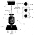
- FIG. 1 is a view showing a schematic view of a fine refractometer according to an embodiment of the present invention
- FIG. 2 is a view illustrating a correlation between a refractive index of a microfluid and an out of focus image in a microrefractometer according to an embodiment of the present invention
- FIG. 3 is a view illustrating a structure of a target of a fine refractometer according to an embodiment of the present invention
- FIG. 4 is a view illustrating in more detail the structure of the target shown in FIG.
- FIG. 5 is a view illustrating an image (field of view) formed on an image plane in a micro refractometer according to an embodiment of the present invention
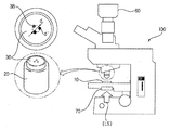
- FIG. 6 is a view illustrating an overall appearance of a fine refractometer according to an embodiment of the present invention.
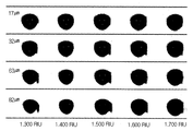
- FIG. 7 is a diagram illustrating a defocused image photographed using a microrefractometer according to an embodiment of the present invention.
- FIG. 8 is a diagram showing a simulation result of measuring the image sensitivity according to the distance between the pinhole of the aperture of the microrefractometer according to the present invention.
- 9A is a measurement simulation graph for the separation of the defocused image according to the channel depth of the target of the microrefractometer according to the present invention.
- FIG. 9B is a measurement simulation graph of a degree of separation of an out-of-focus image according to the refractive index of the microfluid of the target of the microrefractometer according to the present invention.
- FIG. 1 is a view showing a schematic view of a fine refractometer according to an embodiment of the present invention.
- the microrefractometer 100 includes a target 10, an objective lens 20, and an aperture 30.
- the target 10 is a device in which the microfluid to be measured is positioned, and the objective lens 20 is provided to receive light emitted from the light source LS through the target 10.
- the diaphragm 30 positioned at the rear end of the objective lens 20 splits the light emitted from the objective lens 20 and projects the image by the split light OP onto the image plane 40. Since the objective lens 20 may use a well-known thing, the detailed description about the objective lens is abbreviate
- the stop 30 may be provided to have a plurality of pin-holes, but a description will be given of a case in which the microrefractometer 100 according to the present invention described below includes three pinholes. .
- the fine refractometer 100 includes an aperture 30 having three pinholes, and when the light emitted from the light source passes through the target 10, the microfluid is positioned in the target 10, so that the microfluidic refraction index has a refractive index of the microfluid. This results in out-of-focus images 41 and 42 when the light finally reaches the image plane 40. Detailed description of this phenomenon will be described by referring to FIG. 2.
- FIG 2 is a view illustrating a correlation between the refractive index of the microfluid and the out of focus image in the microrefractometer according to the exemplary embodiment of the present invention.
- the refractive index of the light is only affected by the refractive index of the microfluidic fluid when the other factors except the refractive index of the microfluidic fluid itself are kept constant, such as air or glass surfaces.
- the light from the light source passes through the lens plane Lp and the diaphragm plane Ap and finally forms the image plane Ip by varying the degree of refraction (light path) according to the refractive index of the microfluid.
- the degree of out-of-focus that is, the degree of separation of spot images
- the refractive index is n 1 ⁇ n 2
- the degree of defocus is D 1 > D 2 in the image formed on the image plane Ip. That is, in the case of microfluids having a larger refractive index, the degree of out of focus is smaller.
- the refractive index (RI) of the microfluid can be measured using the degree of separation in the out of focus image.
- the present invention provides a microrefractometer capable of self-calibration by imaging a reference fluid having a known refractive index together with the microfluid to be measured in measuring the refractive index of the microfluid. This is specifically realized by improving the structure of the target of the fine refractometer, which will be described below in detail with respect to the structure of the target used in the present invention.
- FIG. 3 is a diagram illustrating a structure of a target of a microrefractometer according to an embodiment of the present invention
- FIG. 4 is a diagram illustrating the structure of the target shown in FIG. 3 in more detail. Is a diagram illustrating an image (field of view) formed in the image plane in the micro refractometer according to an embodiment of the present invention.
- the target microfluidics Sf and the reference fluids 31, 32, 33, and 34 are positioned on the target 10.
- a portion in which the microfluidic Sf is positioned in the target 10 may be a measurement region, and a portion in which the reference fluids 31, 32, 33, and 34 are positioned may be referred to as a correction region.
- the target 10 may be configured through five channels.
- one channel sample channel
- reference may be provided in the measurement region 51 in which the microfluidics S f are positioned.
- Four channels reference channels are provided in the correction region 52 in which the fluids 31, 32, 33, and 34 are positioned.
- Reference fluids having different refractive indices are positioned in the reference channels.
- their refractive indices have a known value.
- the target 10 includes a sample channel and a reference channel, and an opaque pattern 15 is included at the bottom of each channel.
- the opaque pattern 15 is opaque except that the transparent spot 13 is formed so that the light of the light source can be transmitted to the central portion thereof.
- it is usually formed by sputtering chromium, but a variety of known metal materials other than chromium may be used as the material for forming the opaque pattern.
- a transparent pattern may be included in the bottom portion of the channel, and in contrast to the opaque pattern, the center portion thereof may be transparent except that an opaque spot is formed.
- the depths h of the channels formed in the target 10 are all the same. Therefore, the parameter regarding the depth h of the channel can be ignored.
- out-of-focus images of the measurement area 51 and the correction area 52 are imaged in the same image plane to achieve self-calibration in the measurement of the refractive index through the microrefractometer.
- Another parameter is the distance between the target 10 and the objective lens because the microfluidic object S f and the reference fluids 31, 32, 33, 34 are all on the same plane. It is also possible to ignore it.
- FIG. 6 is a view illustrating the overall appearance of a fine refractometer according to an embodiment of the present invention.
- the micro refractometer 100 includes a target 10, an objective lens 20, an aperture 30, a camera 60, and an optical filter 70.
- the description of the target 10, the objective lens 20, and the optical filter 70 will be replaced with the above description, and the camera 60 and the aperture 30 will be described.
- the camera 60 captures an image formed on the image plane (see 40 in FIG. 1) by the light passing through the aperture 30, and a CCD camera may be generally used.
- the diaphragm 30 has three pinholes 38, where d is the diameter size of the imaginary circumscribed circle connecting the pinholes, and d ⁇ means the diameter size of each pinhole.
- the d is preferably formed in the range 1.0 ⁇ 5.0 mm.
- FIG. 7 is a diagram illustrating a defocused image photographed using a microrefractometer according to an embodiment of the present invention.
- the out-of-focus image has a greater degree of separation than the microfluid having a high refractive index in the case of the microfluid having a low refractive index.
- the separation of the defocused image means the interval between spots of the image, and the high separation means that the distance between the spot images is far, and that the sensitivity of the image is high.
- FIG. 8 is a diagram illustrating a simulation result of measuring image sensitivity according to a diameter (d) of a virtual circumscribed circle connecting a pinhole of an aperture of a microrefractometer according to the present invention.
- 9A is a measurement simulation graph of a degree of separation of an out of focus image according to a channel depth of a target of the microrefractometer according to the present invention.
- ⁇ D / ⁇ h was measured as 0.25, 0.17, 0.10, and 0.04 pixel / ⁇ m for microfluids having refractive indexes of 1.3, 1.4, 1.5, and 1.6 Refractive Index Units (RIUs), respectively.
- FIG. 9B is a measurement simulation graph of a degree of separation of an out-of-focus image according to the refractive index of the microfluid of the target of the microrefractometer according to the present invention.
- the graph shown in FIG. 9B shows the relationship of ⁇ D according to the refractive index (RI) of the microfluid.
- the separation ⁇ D of the defocused image has a large separation when the refractive index RI is small, and the deeper the channel depth h of the target, the larger the separation.
- the separation (sensitivity, sensitivity) is 13.21, 20.61, 39.95, and 53.66 pixel / RIU, respectively, when the channel depth (h) is 17, 32, 63, and 82 ⁇ m. Therefore, the deeper the channel depth, the greater the separation of images.
- Table 1 Reference fluid RI for calibration sample RI Measured RI mean Standard deviation 1.3, 1.5, 1.6, 1.7 1.400 1.4002 ⁇ 0.0013 1.3, 1.4, 1.6, 1.7 1.500 1.4998 ⁇ 0.0009 1.3, 1.4, 1.5, 1.7 1.600 1.6002 ⁇ 0.0010
- the measurement is performed when the microfluid (sample RI) having a known refractive index is measured.
- Measured RI mean in the results was measured as 1.4002 for a sample having a refractive index of 1.400, 1.4998 for a sample having a refractive index of 1.500 and 1.6002 for a sample having a refractive index of 1.600.
Landscapes
- Physics & Mathematics (AREA)
- Health & Medical Sciences (AREA)
- Life Sciences & Earth Sciences (AREA)
- Chemical & Material Sciences (AREA)
- Analytical Chemistry (AREA)
- Biochemistry (AREA)
- General Health & Medical Sciences (AREA)
- General Physics & Mathematics (AREA)
- Immunology (AREA)
- Pathology (AREA)
- Engineering & Computer Science (AREA)
- Mathematical Physics (AREA)
- Theoretical Computer Science (AREA)
- Spectroscopy & Molecular Physics (AREA)
- Investigating Or Analysing Materials By Optical Means (AREA)
Abstract
La présente invention concerne un microréfractomètre utilisant l'imagerie défocalisante. Plus particulièrement, le microréfractomètre selon la présente invention comprend : une cible sur laquelle un microfluide cible et un fluide étalon dont l'indice de réfraction est déjà connu sont positionnés; une lentille d'objet recevant de la lumière incidente qui a été produire par une source de lumière et a traversé la cible; un orifice comprenant une pluralité de trous d'épingle qui divergent un trajet lumineux de la lumière incidente sur la lentille d'objet; et une caméra recevant une image défocalisante formée sur un plan d'image d'un réfractomètre par la lumière qui a traversé l'orifice.
Priority Applications (1)
| Application Number | Priority Date | Filing Date | Title |
|---|---|---|---|
| US13/703,805 US8649003B2 (en) | 2010-09-08 | 2011-09-07 | Microrefractometer using defocusing imaging |
Applications Claiming Priority (2)
| Application Number | Priority Date | Filing Date | Title |
|---|---|---|---|
| KR10-2010-0087744 | 2010-09-08 | ||
| KR1020100087744A KR101141099B1 (ko) | 2010-09-08 | 2010-09-08 | 초점 이탈 이미징을 이용한 미세 굴절계 |
Publications (2)
| Publication Number | Publication Date |
|---|---|
| WO2012033341A2 true WO2012033341A2 (fr) | 2012-03-15 |
| WO2012033341A3 WO2012033341A3 (fr) | 2012-05-03 |
Family
ID=45811077
Family Applications (1)
| Application Number | Title | Priority Date | Filing Date |
|---|---|---|---|
| PCT/KR2011/006620 Ceased WO2012033341A2 (fr) | 2010-09-08 | 2011-09-07 | Microréfractomètre utilisant l'imagerie défocalisante |
Country Status (3)
| Country | Link |
|---|---|
| US (1) | US8649003B2 (fr) |
| KR (1) | KR101141099B1 (fr) |
| WO (1) | WO2012033341A2 (fr) |
Families Citing this family (3)
| Publication number | Priority date | Publication date | Assignee | Title |
|---|---|---|---|---|
| KR101159696B1 (ko) | 2010-10-25 | 2012-06-25 | 광주과학기술원 | 다중 핀홀과 스팟 패턴 타겟을 이용한 굴절계 |
| JP6217748B2 (ja) * | 2013-06-24 | 2017-10-25 | 株式会社島津製作所 | 屈折率測定装置 |
| KR101712429B1 (ko) * | 2015-09-24 | 2017-03-08 | 대한민국(관리부서 질병관리본부장) | 표면-증강 라만 산란 기반의 탄저균 검출용 미세유체칩 및 이를 이용한 탄저균 검출 방법 |
Family Cites Families (8)
| Publication number | Priority date | Publication date | Assignee | Title |
|---|---|---|---|---|
| EP0023577B1 (fr) * | 1979-07-06 | 1985-11-21 | Kabushiki Kaisha Toshiba | Mesure de la tension superficielle |
| JPH0718791B2 (ja) * | 1989-11-30 | 1995-03-06 | 大塚電子株式会社 | 示差屈折率計 |
| JPH0518893A (ja) * | 1991-07-12 | 1993-01-26 | Matsushita Electric Ind Co Ltd | 屈折率測定装置 |
| US5309214A (en) * | 1991-09-17 | 1994-05-03 | Olympus Optical Co., Ltd. | Method for measuring distributed dispersion of gradient-index optical elements and optical system to be used for carrying out the method |
| US5355211A (en) * | 1993-04-02 | 1994-10-11 | Leica Inc. | Refractometer subassembly method and apparatus |
| JP2004150923A (ja) * | 2002-10-30 | 2004-05-27 | Atago:Kk | 屈折計 |
| JP4384463B2 (ja) | 2003-09-22 | 2009-12-16 | オリンパス株式会社 | 焦点検出ユニット並びにそれを用いた屈折率測定装置及び非接触温度計 |
| US7365835B2 (en) | 2003-12-02 | 2008-04-29 | California Institute Of Technology | Dark-field laser-scattering microscope for analyzing single macromolecules |
-
2010
- 2010-09-08 KR KR1020100087744A patent/KR101141099B1/ko not_active Expired - Fee Related
-
2011
- 2011-09-07 US US13/703,805 patent/US8649003B2/en not_active Expired - Fee Related
- 2011-09-07 WO PCT/KR2011/006620 patent/WO2012033341A2/fr not_active Ceased
Also Published As
| Publication number | Publication date |
|---|---|
| US20130208266A1 (en) | 2013-08-15 |
| KR101141099B1 (ko) | 2012-05-02 |
| KR20120025694A (ko) | 2012-03-16 |
| US8649003B2 (en) | 2014-02-11 |
| WO2012033341A3 (fr) | 2012-05-03 |
Similar Documents
| Publication | Publication Date | Title |
|---|---|---|
| US10302924B2 (en) | Optical microscope | |
| WO2015088102A1 (fr) | Procédé de mesure de propriété de pénétration d'un milieu de transmission de lumière et appareil d'acquisition d'image l'utilisant | |
| JP6546990B2 (ja) | 標本形状測定方法及び標本形状測定装置 | |
| CN113260846B (zh) | 表面颜色和液体接触角成像 | |
| WO2012033341A2 (fr) | Microréfractomètre utilisant l'imagerie défocalisante | |
| CN111656251A (zh) | 功能模块和配备有该功能模块的显微镜 | |
| WO2013036049A2 (fr) | Microscope confocal à fluorescence | |
| TW202232074A (zh) | 用於測定遠焦光學系統的調制轉換函數的量測設備與方法 | |
| KR102690597B1 (ko) | 마이크로렌즈 어레이 기반 초박형 현미경 | |
| WO2022260327A1 (fr) | Système et procédé de mesure précise de turbidité, au moyen d'une figure de speckle | |
| WO2019235908A1 (fr) | Dispositif d'imagerie thermique multi-modes et son procédé de fonctionnement | |
| TWI908298B (zh) | 用於測試光子積體電路的設備、測試卡及方法,以及光子積體電路 | |
| GB2520541A (en) | Optical arrangement for imaging a sample | |
| WO2016068504A1 (fr) | Dispositif spectroscopique multi-fonction | |
| JPWO2018092247A1 (ja) | 標本形状測定方法及び標本形状測定装置 | |
| WO2011059232A2 (fr) | Système optique destiné à un microscope à image thermique | |
| CN222733538U (zh) | 高分辨率光谱共焦测量装置 | |
| KR102010136B1 (ko) | 다중모드 영상의 획득이 가능한 영상 획득 시스템 | |
| US10539411B2 (en) | Sample shape measuring apparatus | |
| CN103592264A (zh) | 在线毛细管电泳及检测装置 | |
| KR101159696B1 (ko) | 다중 핀홀과 스팟 패턴 타겟을 이용한 굴절계 | |
| WO2023146085A1 (fr) | Appareil d'inspection optique | |
| CN117572625B (zh) | 多路显微成像装置与方法 | |
| CN217846791U (zh) | 双视野镜头结构及检测装置 | |
| CN108802992A (zh) | 基于智能手机的样品均匀透射照明拍照装置 |
Legal Events
| Date | Code | Title | Description |
|---|---|---|---|
| 121 | Ep: the epo has been informed by wipo that ep was designated in this application |
Ref document number: 11823774 Country of ref document: EP Kind code of ref document: A2 |
|
| WWE | Wipo information: entry into national phase |
Ref document number: 13703805 Country of ref document: US |
|
| NENP | Non-entry into the national phase |
Ref country code: DE |
|
| 122 | Ep: pct application non-entry in european phase |
Ref document number: 11823774 Country of ref document: EP Kind code of ref document: A2 |