WO2012035726A1 - 生体試料測定システム - Google Patents
生体試料測定システム Download PDFInfo
- Publication number
- WO2012035726A1 WO2012035726A1 PCT/JP2011/005047 JP2011005047W WO2012035726A1 WO 2012035726 A1 WO2012035726 A1 WO 2012035726A1 JP 2011005047 W JP2011005047 W JP 2011005047W WO 2012035726 A1 WO2012035726 A1 WO 2012035726A1
- Authority
- WO
- WIPO (PCT)
- Prior art keywords
- biological sample
- unit
- cradle
- sample measurement
- sample measuring
- Prior art date
- Legal status (The legal status is an assumption and is not a legal conclusion. Google has not performed a legal analysis and makes no representation as to the accuracy of the status listed.)
- Ceased
Links
Images






Classifications
-
- A—HUMAN NECESSITIES
- A61—MEDICAL OR VETERINARY SCIENCE; HYGIENE
- A61B—DIAGNOSIS; SURGERY; IDENTIFICATION
- A61B5/00—Measuring for diagnostic purposes; Identification of persons
- A61B5/74—Details of notification to user or communication with user or patient; User input means
- A61B5/7405—Details of notification to user or communication with user or patient; User input means using sound
-
- G—PHYSICS
- G01—MEASURING; TESTING
- G01N—INVESTIGATING OR ANALYSING MATERIALS BY DETERMINING THEIR CHEMICAL OR PHYSICAL PROPERTIES
- G01N33/00—Investigating or analysing materials by specific methods not covered by groups G01N1/00 - G01N31/00
- G01N33/48—Biological material, e.g. blood, urine; Haemocytometers
- G01N33/50—Chemical analysis of biological material, e.g. blood, urine; Testing involving biospecific ligand binding methods; Immunological testing
- G01N33/66—Chemical analysis of biological material, e.g. blood, urine; Testing involving biospecific ligand binding methods; Immunological testing involving blood sugars, e.g. galactose
-
- A—HUMAN NECESSITIES
- A61—MEDICAL OR VETERINARY SCIENCE; HYGIENE
- A61B—DIAGNOSIS; SURGERY; IDENTIFICATION
- A61B5/00—Measuring for diagnostic purposes; Identification of persons
- A61B5/0002—Remote monitoring of patients using telemetry, e.g. transmission of vital signals via a communication network
-
- A—HUMAN NECESSITIES
- A61—MEDICAL OR VETERINARY SCIENCE; HYGIENE
- A61B—DIAGNOSIS; SURGERY; IDENTIFICATION
- A61B5/00—Measuring for diagnostic purposes; Identification of persons
- A61B5/145—Measuring characteristics of blood in vivo, e.g. gas concentration or pH-value ; Measuring characteristics of body fluids or tissues, e.g. interstitial fluid or cerebral tissue
- A61B5/14532—Measuring characteristics of blood in vivo, e.g. gas concentration or pH-value ; Measuring characteristics of body fluids or tissues, e.g. interstitial fluid or cerebral tissue for measuring glucose, e.g. by tissue impedance measurement
-
- A—HUMAN NECESSITIES
- A61—MEDICAL OR VETERINARY SCIENCE; HYGIENE
- A61B—DIAGNOSIS; SURGERY; IDENTIFICATION
- A61B5/00—Measuring for diagnostic purposes; Identification of persons
- A61B5/74—Details of notification to user or communication with user or patient; User input means
- A61B5/742—Details of notification to user or communication with user or patient; User input means using visual displays
-
- G—PHYSICS
- G01—MEASURING; TESTING
- G01N—INVESTIGATING OR ANALYSING MATERIALS BY DETERMINING THEIR CHEMICAL OR PHYSICAL PROPERTIES
- G01N33/00—Investigating or analysing materials by specific methods not covered by groups G01N1/00 - G01N31/00
- G01N33/48—Biological material, e.g. blood, urine; Haemocytometers
- G01N33/483—Physical analysis of biological material
- G01N33/487—Physical analysis of biological material of liquid biological material
- G01N33/48785—Electrical and electronic details of measuring devices for physical analysis of liquid biological material not specific to a particular test method, e.g. user interface or power supply
- G01N33/48792—Data management, e.g. communication with processing unit
-
- G—PHYSICS
- G16—INFORMATION AND COMMUNICATION TECHNOLOGY [ICT] SPECIALLY ADAPTED FOR SPECIFIC APPLICATION FIELDS
- G16H—HEALTHCARE INFORMATICS, i.e. INFORMATION AND COMMUNICATION TECHNOLOGY [ICT] SPECIALLY ADAPTED FOR THE HANDLING OR PROCESSING OF MEDICAL OR HEALTHCARE DATA
- G16H40/00—ICT specially adapted for the management or administration of healthcare resources or facilities; ICT specially adapted for the management or operation of medical equipment or devices
- G16H40/60—ICT specially adapted for the management or administration of healthcare resources or facilities; ICT specially adapted for the management or operation of medical equipment or devices for the operation of medical equipment or devices
- G16H40/63—ICT specially adapted for the management or administration of healthcare resources or facilities; ICT specially adapted for the management or operation of medical equipment or devices for the operation of medical equipment or devices for local operation
-
- A—HUMAN NECESSITIES
- A61—MEDICAL OR VETERINARY SCIENCE; HYGIENE
- A61B—DIAGNOSIS; SURGERY; IDENTIFICATION
- A61B2560/00—Constructional details of operational features of apparatus; Accessories for medical measuring apparatus
- A61B2560/04—Constructional details of apparatus
- A61B2560/0456—Apparatus provided with a docking unit
Definitions
- the present invention relates to a biological sample measurement system including a biological sample measurement device that measures biological samples such as blood glucose level and lactic acid level.
- Conventional biological sample measuring devices are widely used in medical institutions such as hospitals, for example.
- a plurality of biological sample measuring devices are arranged in the nurse center.
- Each nurse brings a biological sample measuring device to a hospital room, for example, and measures blood glucose level there. And then, it returns to a nurse center and transmits a measured value from each biological sample measuring device to a biological sample data management device (for example, refer to patent documents 1).
- the conventional biological sample measuring device has the following problems. That is, in the hospital, for example, when measuring the blood glucose level of a patient, 3:1 am after waking up, 8 am before breakfast, 9:30 after breakfast, 11:30 before lunch It is necessary to measure at least 8 times, 13:00 after lunch, 17:30 before dinner, 19:00 after dinner, and 20:30 before going to bed.
- the biological sample measurement device used to measure the blood glucose level includes a measurement unit, a first control unit connected to the measurement unit, a first display unit connected to the first control unit, A first recording unit, a first input unit, an operation sound generation unit, an operation setting memory, and a first data transmission / reception unit are provided, and for example, a beep sound is emitted from the operation sound generation unit every time the measurement operation is advanced. It is done. Therefore, patients other than the subject to be measured may wake up or feel uncomfortable with this beep sound.
- the volume of the beep sound generated from the operation sound generating unit is reduced and the brightness of the first display unit is lowered so as not to wake up other patients who are already sleeping. It is required to make it. That is, in the conventional biological sample measuring device, it is necessary to perform measurement by changing the setting of the biological sample measuring device many times during one day. Moreover, since a plurality of biological sample measurement devices are used in medical institutions such as hospitals, the setting is extremely complicated and unusable.
- an object of the present invention is to provide a biological sample measurement system capable of efficiently setting a biological sample measurement device even when a plurality of biological sample measurement devices are used in a medical institution such as a hospital.
- the present invention includes first and second biological sample measuring devices for measuring a biological sample.
- Each of the first and second biological sample measuring apparatuses includes a measuring unit, a control unit, a display unit, a recording unit, an input unit, and a data transmitting / receiving unit.
- the measurement unit measures a biological sample.
- the control unit is connected to the measurement unit.
- the display unit is connected to the control unit and displays measurement results and set values in the measurement unit.
- the recording unit stores measurement results and set values.
- the input unit inputs a set value.
- the data transmission / reception unit transmits / receives information regarding the set value.
- the control unit transmits the information related to the setting value changed through the input unit to the second biological sample measuring device through the data transmitting / receiving unit, and the second biological sample measuring device.
- the control unit changes the setting value based on the information regarding the setting value transmitted from the first biological sample measuring device.
- the setting of one first biological sample measuring device is set to the first setting value
- the set first setting value is transmitted to the second biological sample measuring device
- the setting of the second biological sample measuring device is automatically set to the first set value.
- FIG. 2 is an electrical block diagram of the biological sample measurement system of FIG. 1.
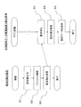
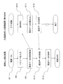
- movement flowchart of the biological sample measuring system of FIG. The figure which shows the structure of the biological sample measuring system containing the biological sample measuring device which concerns on other embodiment of this invention.
- FIG. 6 is an electrical block diagram of the biological sample measurement system of FIG. 5.
- movement flowchart of the biological sample measuring system of FIG. The figure which shows the structure of the biological sample measuring system containing the biological sample measuring device which concerns on further another embodiment of this invention.
- FIG. 9 is an electrical block diagram of the biological sample measurement system of FIG. 8.
- FIG. 9 is an electrical block diagram of the biological sample measurement device of FIG. 8.
- movement flowchart of the biological sample measuring apparatus of FIG. The figure which shows the structure of the biological sample measuring system containing the biological sample measuring device which concerns on further another embodiment of this invention.
- FIG. 16 is an electrical block diagram of the biological sample measurement device of FIG. 15. The operation
- the biological sample measurement system of the present embodiment includes a biological sample data management device 1 installed in a nurse center of a hospital and a biological sample measurement device electrically connected to the biological sample data management device 1. 2, 3, 4.
- the biological sample measuring devices 2, 3, and 4 are connected to the biological sample data management device 1 as shown in FIGS. Since the biological sample measurement devices 2, 3, and 4 basically have the same configuration, FIG. 2 will be described by taking the configuration of the biological sample measurement device 2 as an example.
- the biological sample measurement device 2 includes a measurement unit 5 that measures blood glucose levels, a control unit 6 connected to the measurement unit 5, a display unit 7, a recording unit 8, an input unit 9, and a battery connected to the control unit 6. 10, a bar code reader 11, an operation sound generation unit 12, an operation setting memory (recording unit) 13, and a data transmission / reception unit 14.
- the measurement unit 5 is connected to a detection unit 15 that detects that a blood glucose level sensor (not shown) is attached to the biological sample measurement device 2.
- a blood glucose level sensor not shown
- the recording unit 8 and the operation setting memory 13 are provided separately.
- the recording unit 8 mainly stores measurement-related data such as a blood glucose level, and the operation setting memory 13 sets the operation setting memory 13. Data such as values, judgment values, and various parameters are stored.
- the recording unit 8 and the operation setting memory 13 are not necessarily provided separately.
- the input unit 9 includes operation buttons (for example, a power button (start button), a determination button, a menu button, a cross key for selecting / setting, or the like provided on the outer surface of the biological sample measuring device 2, 3, 4).
- operation buttons for example, a power button (start button), a determination button, a menu button, a cross key for selecting / setting, or the like provided on the outer surface of the biological sample measuring device 2, 3, 4.
- the input unit 9 selects the power ON or measurement mode, and the barcode reader 11 selects the nurse. ID, patient ID, and blood glucose sensor ID are read.
- the biological sample measuring devices 2, 3, and 4 of the present embodiment are measuring instruments for medical institutions.
- the biological sample measurement devices 2, 3, and 4 of the present embodiment are intended for a plurality of patients and are used by a plurality of measurers (such as nurses), such an operation is performed on measurement data. It is indispensable for accurate management, and this completes preparation for measurement.
- a blood glucose level sensor is loaded into a sensor mounting part (not shown) of the biological sample measuring device 2
- the blood of the target patient is punctured to exude blood, and the blood is spotted on the blood glucose level sensor.
- the blood glucose level is measured in the measurement unit 5 and displayed on the display unit 7. Further, the measured value and the ID are associated and recorded in the recording unit 8.
- the detection unit 15 provided in the sensor mounting unit, whether or not the blood glucose level sensor is correctly mounted (for example, whether the front and back of the blood glucose level sensor are reversed or the type of the blood glucose level sensor is incorrect). Detection).
- information on the measured time is also recorded in the recording unit 8 in association with the measured value, patient ID, nurse ID, and the like.
- Such an operation mode is executed in accordance with the set value recorded in the operation setting memory 13.
- the set value of the biological sample measuring device 2 is set / changed by an input from the input unit 9.
- the operation setting memory 13 is configured by an EEPROM (Electrically Erasable Programmable Read-Only Memory) which is a kind of nonvolatile memory so that such setting values can be set and thereafter changed.
- EEPROM Electrically Erasable Programmable Read-Only Memory
- the operation setting memory 13 is fixedly provided inside the biological sample measuring apparatus 2, but a replaceable memory (for example, an SD memory or the like) may be used instead. it can. Similarly, a replaceable memory (for example, an SD memory) can also be used for the recording unit 8.
- a replaceable memory for example, an SD memory
- the setting values set in the operation setting memory 13 of the biological sample measuring device 2 are input and changed to the operation setting memory 13 of the biological sample measuring devices 3 and 4.
- the data is transmitted to the biological sample measuring devices 3 and 4 via the sample data management device 1 and written to the operation setting memory 13 of the biological sample measuring devices 3 and 4.
- the biological sample measuring devices 2, 3, and 4 are set to the same set value and operate.
- the biological sample data management device 1 includes a data transmission / reception unit 16 that performs data transmission / reception with the data transmission / reception unit 14 of the biological sample measurement device 2 via wireless (wired), and data transmission / reception.
- the control unit 17 connected to the unit 16, the display unit 18, the recording unit 19, and the input unit 20 connected to the control unit 17 are included.
- the blood glucose measurement value associated with each ID information transmitted from the recording unit 8 of the biological sample measurement device 2 to the biological sample data management device 1 via the data transmission / reception units 14 and 16 is displayed on the display unit 18. And is recorded in the recording unit 19.
- biological sample measuring devices 3 and 4 are also connected to the biological sample data management device 1. For this reason, the blood glucose measurement value associated with each ID information obtained by the biological sample measuring devices 3 and 4 is displayed on the display unit 18 and recorded in the recording unit 19.
- the input unit 20 is operated when data transmission / reception is performed between the biological sample measurement devices 2, 3, 4 and the biological sample data management device 1.
- the biological sample measuring devices 2, 3, and 4 included in the biological sample measuring system of the present embodiment measure the blood glucose level of the patient in the hospital. And the measurement of a blood glucose level is implemented 8 times a day, for example in the case of many patients.
- blood glucose level measurement is required at least 8 times. As described above, since the blood glucose level is measured eight times a day, it is necessary to give consideration to patients other than the measurement subject at the time of measurement immediately after the wake-up time, for example.
- the setting is changed so that the volume of the beep sound generated from the operation sound generation unit 12 is reduced during measurement immediately after the wake-up time. That is, before the measurement immediately after the wake-up time, specifically, after the final measurement on the previous day, a nurse who is a measurer enters the operation setting memory 13 via the input unit 9 of the biological sample measurement device 2 at the nurse station.
- the setting of the biological sample measuring device 2 is changed so that the volume of the beep sound from the operation sound generating unit 12 is reduced (S1).
- the biological sample measurement device 2 whose settings have been changed is connected to the biological sample data management device 1 (S2).
- the input unit 9 of the biological sample measurement device 2 is operated to transmit the changed set value to the biological sample data management device 1 (S3).
- the biological sample data management apparatus 1 is in a request waiting state (S4).
- the changed set value is received from the biological sample measurement device 2 (S5), and then this set value is stored in the recording unit 19 of the biological sample data management device 1 (S6).
- the biological sample measuring devices 3 and 4 returning to the nurse station are turned on (S7).
- the passwords of the respective biological sample measuring devices 3 and 4 are input (S8).
- a setting value reception request is transmitted to the biological sample data management apparatus 1 (S9).
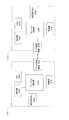
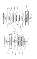
- the biological sample data management device 1 is in a request waiting state (S10). Therefore, when there is a request for receiving a set value, the set value stored in the recording unit 19 is read (S11), and transmitted to the requested biological sample measuring devices 3 and 4 (S12). . Next, the biological sample measurement devices 3 and 4 receive the changed set value of the biological sample measurement device 2 from the biological sample data management device 1 (S13), and store it in its own operation setting memory 13 (S14). ).
- the biological sample data management device 1 when changing the operation settings of the biological sample measurement devices 2, 3, and 4, only the set value of the biological sample measurement device 2 is changed by the input unit 9, and thereafter, the biological sample data management device 1. By receiving the above set value via communication with, the operation settings of the biological sample measuring devices 3 and 4 can be easily changed. As a result, it is possible to provide a biological sample measurement system that is extremely easy to use. And, as described above, by measuring the blood glucose level of the patient after getting up using the biological sample measuring devices 2, 3, and 4 set so that the volume of the beep sound is reduced, The patient can be prevented from waking up or feeling uncomfortable with a beep.
- the biological sample measurement system of the present embodiment measurement of the blood glucose level after waking up is completed, and the measurement value is transmitted to the recording unit 19 of the biological sample data management device 1, and then the input unit 9 of the biological sample measurement device 2.
- the setting is changed to increase the volume of the beep again.
- the setting value after the change of the biological sample measuring device 2 is transmitted to the biological sample measuring devices 3 and 4 by the procedure shown in FIGS. .
- the measurer can surely confirm the operation by the beep sound whose volume is increased.
- the volume of the beep sound generated from the operation sound generating unit 12 is reduced so as not to wake up other patients who are already sleeping, and the brightness of the display unit 7 is reduced. Consideration is required. Therefore, in this embodiment, after the measurement of the blood glucose level after supper is finished and the measurement value is transmitted to the recording unit 19 of the biological sample data management device 1, the input unit 9 of the biological sample measurement device 2 is operated. The setting is changed so that the volume of the beep sound is reduced and the luminance of the display unit 7 is decreased.
- the setting value after the change of the biological sample measuring device 2 is transmitted to the biological sample measuring devices 3 and 4 by the procedure shown in FIGS. .
- the setting value after the change of the biological sample measuring device 2 is transmitted to the biological sample measuring devices 3 and 4 by the procedure shown in FIGS. .
- in order to measure a biological sample in a hospital it may be necessary to change the settings of the plurality of biological sample measuring devices 2, 3, and 4 many times during a day.
- the biological sample measurement system of the present embodiment in practice, it is possible to automatically change the settings of the other biological sample measurement devices 3 and 4 simply by changing one biological sample measurement device 2. Therefore, it is possible to improve the convenience of the measurer. Furthermore, in the above description, the example in which the setting data of the biological information measuring device 2 is transmitted to the other biological information measuring devices 3 and 4 and changed is shown. Need not be based on For example, the setting data of the biological information measuring device (terminal) 3 or the biological information measuring device (terminal) 4 may be used as a reference.
- the data link related to the setting change is performed only by the biological sample measurement devices 2, 3, and 4 without using the biological sample data management device 1. .
- the description will be divided into two patterns.
- (I) Master Fixation Method In the biological sample measurement system of the present embodiment, for example, the biological sample measurement device 2 is fixed to the master terminal, and information related to various setting changes is transmitted and received between the biological sample measurement devices 2, 3, and 4. It is possible to adopt a method to
- each of the biological sample measuring devices 2, 3, and 4 includes a data transmitting / receiving unit 14 having a wired or wireless communication function.
- communication methods using a wired system include USB, LAN, and RS-232C.
- communication means using a wireless system there are a wireless LAN, Bluetooth, an infrared communication system, and the like.
- setting values are transmitted / received between the biological sample measuring device 2 on the master side and the other biological sample measuring device 3 via the mutual data transmitting / receiving unit 14.
- the master-side biological sample measuring device 2 first inputs (changes) set values such as the volume of the beep sound and the brightness of the display unit 7 as necessary (S21). ).
- the biological sample measuring device 2 on the master side is set to the transmission state (S22).
- information on the set value is transmitted from the biological sample measuring device 2 on the master side to the other biological sample measuring devices 3 and 4.
- the other terminal biological sample measuring device 3, 4
- the other terminal receives information on the set value from the biological sample measuring device 2 on the master side (S 24). S25).
- each of the biological sample measuring devices 3 and 4 the data of the set value in the operation setting memory 13 in each of the biological sample measuring devices 3 and 4 is updated and stored (S26). The same applies when a new biological sample measuring device is added or replaced.
- the biological sample measuring devices 3 and 4 can also set a common setting value with the biological sample measuring device 2.
- the biological sample measurement device whose setting has been changed first may be recognized as the master device, and the other biological sample measurement device may be recognized as the sleeve side.
- the biological sample measuring device 3 serves as a master terminal and changes the setting data. Get ready for transmission.
- the “master terminal” flag indicating that it is a master terminal is turned on, and itself shifts to a transmission state and enters transmission preparation.
- the other biological sample measuring devices 2 and 4 are connected to the master biological sample measuring device 3 for communication, they are ready to receive from the biological sample measuring device 3 on the master side. As a result, a transition is made to a state waiting for a “transmission request” from the biological information measuring device 3 on the master side.
- the biological sample measuring device 3 on the master side confirms the reception state of the other biological information measuring devices 2 and 4 (after transmitting the transmission request and confirming the response), and then transmits the setting data to the other biological sample. Transmit to the measuring devices 2 and 4.
- the other biological sample measuring devices 2 and 4 receive setting data and the like from the biological sample measuring device 3 on the master side, and store them in the internal operation setting memory 13 mounted on each of the biological sample measuring devices 2 and 4. Store and update.
- the biological sample is simply set manually in the biological sample measuring device 2 on the master side.
- a set value common to the biological sample measuring device 2 can be set. Further, by not fixing to the master machine, even if the biological sample measuring device serving as the master machine fails or is lost, it is possible to respond to the occasional circumstances and configure this biological sample measuring system.
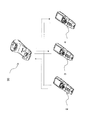
- FIG. 8 A biological sample measurement system according to still another embodiment of the present invention will be described below.
- the set value is changed between the biological sample measurement devices 2, 3, 4 via the cradle 30 instead of the biological sample data management device 1. It differs from the first embodiment in that information is transmitted and received.
- components having the same functions as those in the first embodiment are denoted by the same reference numerals and description thereof is omitted.
- the change information of the setting value is shared between 3 and 4.
- setting data of a predetermined terminal biological sample measurement device 2 is transmitted to the cradle 30.
- a method for transmitting the setting data three methods can be employed: a wired method, a wireless method, and a method of directly transmitting via the connector when the biological sample measuring device 2 is loaded in the cradle 30.
- the timing at which the cradle 30 receives the setting data of the predetermined biological sample measuring device 2 can be the following three types.
- a method of starting by pressing an operation button of a predetermined biological sample measuring device 2 (in this case, the biological sample measuring device 2 may or may not be loaded in the cradle 30).
- a method of receiving setting data of a predetermined terminal biological information measuring device 2 by the cradle 30 and storing it in its internal memory by pressing the “send / receive button”
- a method of starting by pressing an operation button of the biological sample measuring devices 3 and 4 (in this case, the biological sample measuring devices 3 and 4 may or may not be loaded in the cradle 30).
- the predetermined terminal may employ either a fixed method or a random method as in the second embodiment.
- the cradle 30 included in the biological sample measurement system of the present embodiment includes a charging unit 31, a cradle control unit 32, a memory 33, a data transmission / reception unit 34, and a display unit 35, as shown in FIG. And a transmission / reception button 36.
- the charging unit 31 charges the battery 10 mounted on the biological sample measuring devices 2, 3, 4 when the cradle 30 is loaded with the biological information measuring device.
- the cradle control unit 32 performs control on the cradle 30 side, and performs charging control / setting data transmission / reception / transmission / reception button 36 and other input unit scan / data recording / reproduction to / from the memory 33, and display command to the display unit 35. Do.
- the memory 33 stores setting data and the like.
- the data transmission / reception unit 34 transmits / receives setting data and the like to / from the data transmission / reception unit 14 of each biological sample measurement device 2, 3, 4.
- the display unit 35 may have a display such as an LCD (Liquid Crystal Display). Further, the display unit 35 displays a charging state, a communication state, presence / absence / update of setting data, and the like. Further, the charging state, the communication state, and the update state of the setting data are displayed by lighting / flashing the LED (s).
- the transmission / reception button 36 is used when starting data communication between each biological sample measuring device 2, 3, 4 and the cradle 30.
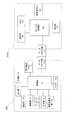
- FIG. 10 is a flowchart showing a flow until the setting data of the biological sample measurement device 2 is transmitted to the cradle 30 and stored in the system activated by operating the transmission / reception button 36 of the cradle 30.
- the set value is input / changed via the input unit 9 (S31).
- the biological sample measurement device 2 is connected for communication with the cradle 30 (S32).
- the biological sample measurement device 2 is not necessarily loaded in the cradle 30.
- the communication connection is activated by operating the activation button of the input unit 9, and the communication connection is established by automatically shifting to the transmission state when the set value input operation is completed. But you can.
- the biological sample measurement device 2 becomes in a state where communication connection with the cradle 30 is possible, and is in a transmission state with respect to the cradle 30 (S33).
- data related to the changed set value is transmitted from the biological sample measuring device 2 to the cradle 30 (S34).
- the cradle 30 side stands by until the transmission / reception button 36 (or the reception button 36a) is operated.
- the cradle 30 is connected to the biological sample measuring apparatus 2 (S36).
- the cradle 30 is in a state where communication connection is possible with the biological sample measuring device 2, and receives information on the set value from the biological sample measuring device 2 (S38).
- the cradle 30 stores information on the set value received from the biological sample measurement device 2 in the internal memory 33 (S39).
- FIG. 11 shows that the information regarding the changed setting value transmitted from the cradle 30 that has received the information regarding the setting value from the biological sample measuring device 2 is received and stored in the other terminals (biological sample measuring devices 3 and 4). It is a flowchart which shows the flow until it is performed.
- the biological sample measuring devices 3 and 4 transmit a reception request for information on the changed set value to the cradle 30 (S43).
- the biological sample measuring devices 3 and 4 are in a state where communication connection with the cradle 30 is possible, and receive information on the changed set value from the cradle 30 (S44).
- the biological sample measuring devices 3 and 4 store the received information regarding the set values in the operation setting memory 13 (S45).
- the changed set value is read from the memory 33 (S49) and transmitted to the biological sample measuring devices 3 and 4 (S50).
- information on the set value after the change in the biological sample measurement device 2 is obtained via the cradle 30 that charges each biological sample measurement device 2, 3, 4. Sharing between the devices 3 and 4.
- the other biological sample measuring device 3 can be simply set by the biological sample measuring device 2 on the master side.
- 4 can also set a common setting value with the biological sample measuring apparatus 2.
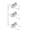
- the biological sample measurement system of the present embodiment communication is performed between the cradles 131, 132, and 133, and updated setting data stored in the memory of the cradle serving as the master machine is transmitted to the other cradles.
- a terminal (biological sample measuring device) corresponding to each cradle is set.
- the setting data is transmitted and received only by the terminal (biological sample measuring device), whereas in the present embodiment, each terminal (biological sample measuring device 2, 3, 4). ) Is different in that setting data is transmitted / received between the cradles 131, 132, and 133 loaded with the.
- each cradle 131, 132, 133 includes data transmission / reception units 34A, 34B as communication units having a wired or wireless communication function.
- the wired system includes USB, LAN, RS-232C, and the like.
- the wireless system includes a wireless LAN, Bluetooth, an infrared communication system, and the like.
- each cradle 131, 132, 133 is provided corresponding to each terminal (biological sample measuring device 2, 3, 4).
- a system in which a predetermined cradle is fixed as a master cradle may be used, or a system in which a master cradle is selected at random may be used.
- 15 shows a state in which the biological sample measuring devices 2, 3, and 4 are loaded in the cradles 131, 132, and 133, respectively, but all the biological sample measuring devices 2, 3, and 4 are not necessarily included.
- the cradle 131, 132, 133 need not be loaded. Therefore, the set values can be updated by loading each biological sample measuring device 2, 3, 4 in the corresponding cradle 131, 132, 133 as necessary.
- FIG. 16 is a block diagram showing the configuration of the cradle 131, 132 included in the biological sample measurement system of the present embodiment.
- the hardware configuration of the cradles 131 and 132 (the same applies to the cradle 133) is the same. However, in this embodiment, since setting values are transmitted and received between the cradles 131, 132, and 133, as shown in FIG. 16, the data transmitting and receiving units 34A and 34B provided in each cradle 131, 132 and the like are used. To do.
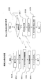
- FIG. 17 is a flowchart showing a procedure for changing the setting in each of the biological sample measuring devices 2, 3, and 4 by the biological sample measuring system of the present embodiment.
- the set value of the terminal (biological sample measuring device 2) stored in the cradle 131 (master cradle) of the present embodiment is transmitted to the cradle 132 will be described.
- the set value of the biological sample measuring device 2 is stored in the memory 33A of the cradle 131 (S71) (Note that the method of fetching the set value into the memory 33A is the flowchart of the third embodiment (FIG. 10). ).
- the communication connection between the cradle 131 and the cradle 132 is confirmed (S74).
- the communication connection is confirmed, information on the set value is transmitted from the cradle 131 to the cradle 132 (S75).
- S76 when it is confirmed on the cradle 132 side that there is a “transmission request” from the cradle 131 (S76), a communication connection is established and a reception state is established (S77).
- the cradle 132 receives information related to the setting value from the cradle 131 (S78). Next, the cradle 132 stores the received information regarding the set value in the internal memory 33B (S79). Next, it is confirmed whether or not the biological sample measuring device 3 is loaded in the cradle 132 (S80). If it is not loaded, an end process is performed (S80).
- the setting value of another biological sample measuring device may be automatically changed with reference to the biological sample measuring device whose setting value is manually changed first, and any biological sample measuring device is used as a reference master machine. It is also possible. Further, the number of biological sample measuring devices included in the biological sample measuring system of the present invention is not limited to the above-described three units, and may be any number as long as it is two or more.
- the volume of the beep sound and the luminance of the display unit 7 have been described as examples of parameters that are changed in settings in the biological sample measurement devices 2, 3, and 4.
- the present invention is not limited to this.
- the types of beep sound described above include a sound upon completion of measurement, a warning sound indicating a measurement error, and an alarm sound indicating a scheduled time of measurement, but of course not limited thereto. It may be a melody sound or a voice notification.
- determination value related to measurement In addition to setting data related to control of beep sound, melody sound, voice, and brightness of display unit, determination value related to measurement, change / registration of patient ID (identification) data of target patient accompanying patient change, or patient ID input Selection of permission / inhibition of setting (whether or not to input), selection / registration of nurse ID data change / registration or change of nurse ID input setting according to change of nurse in charge as a measurer,
- the present invention can be applied in the same manner even when changing the setting values of other parameters, such as changing the measurement execution schedule (common part) data.
- the hospital it is necessary to measure blood glucose levels of many patients simultaneously (almost simultaneously) after waking up. That is, during this time period, many nurses use many blood glucose measuring devices.
- the input setting of the nurse ID and the patient ID is selected as “input”, and the ID information is obtained at the same time before the measurement, and the Used for secure management.
- (C) In the third embodiment, an example in which data transmission / reception between the biological sample measurement device 2 and the cradle 30 is performed via a wireless or wired communication unit has been described.
- the present invention is not limited to this.
- data connector units 14a and 37 are provided instead of the data transmitting and receiving units 14 and 34, as shown in FIG.
- the biological sample measurement system may perform data transmission / reception between the biological sample measurement device 2A and the cradle 30A via the units 14a and 37.
- the other biological sample measuring devices 3A and 4A are assumed to have the same configuration as the biological sample measuring device 2A.
- the data connector units 14a and 37a are included in a type of the data transmitting / receiving unit of the present invention.
- the data connector unit 14a and the data connector unit 37 are electrically connected, and data such as setting data can be transmitted and received. Further, in this configuration, the data connector unit 37 detects that the biological sample measuring device 2A has been loaded in the cradle 30A, thereby automatically transmitting / receiving setting data from the biological sample measuring device 2 to the cradle 30A. Can do. Therefore, the “transmission / reception button 36” described in the third embodiment is not necessarily required.
- FIG. 13 and FIG. 14 are flowcharts showing the procedure for changing the setting of each biological sample measuring device by the biological sample measuring system shown in FIG.
- the flow in the case of adopting a method of automatically starting by loading the biological sample measuring device 2A into the cradle 30A is shown.
- the set value is input / changed via the input unit 9 (S51).
- the biological sample measuring device 2A is loaded into the cradle 30A (S52)
- the connection between the data connector portion 37 of the cradle 30A and the data connector portion 14a of the biological sample measuring device 2A is completed (S53).
- the set value of the biological sample measuring device 2A is transmitted to the cradle 30A (S54).
- the biological sample measuring device 2A is removed from the cradle 30A (S55), and the process is terminated.
- connection confirmation in the data connector unit 37 detection that the biological sample measuring device 2A is loaded is performed (S56).
- the cradle 30A receives the set value of the biological sample measuring device 2A (S57).
- the cradle 30A stores the received setting value in the internal memory 33 (S58).
- disconnection confirmation detection that the biological sample measuring device 2A has been removed from the cradle 30A is performed in the data connector unit 37 (S59), and the process is terminated.
- the biological sample measuring devices 3A and 4A when loaded into the cradle 30A (S61), the connection of the data connector unit 14a is confirmed (S62). Next, the biological sample measuring devices 3A and 4A receive information about the set value via the data connector unit 14a (S63).
- the biological sample measuring devices 3A and 4A store the received information regarding the set values in the operation setting memory 13 (S64).
- the biological sample measuring devices 3A and 4A are removed from the cradle 30A (S65), and the processing is completed.
- the data connector unit 37 confirms the connection with the biological sample measuring devices 3A and 4A (S66).
- the cradle 30A transmits information regarding the set value received from the biological sample measuring device 2A to the biological sample measuring devices 3A and 4A (S67).
- the process ends.
- the first set value is transmitted to the second biological sample measuring device, and the second biological sample measuring device is also the first. Since the setting value is set to 1, there is no need to individually operate and set the settings of the plurality of biological sample measuring devices, and the setting of the plurality of biological sample measuring devices can be performed efficiently. Therefore, for example, it is expected to be utilized as a biological sample measurement system including a plurality of biological sample measurement devices used in hospitals.
Landscapes
- Health & Medical Sciences (AREA)
- Life Sciences & Earth Sciences (AREA)
- Engineering & Computer Science (AREA)
- Biomedical Technology (AREA)
- Physics & Mathematics (AREA)
- General Health & Medical Sciences (AREA)
- Molecular Biology (AREA)
- Medical Informatics (AREA)
- Biophysics (AREA)
- Pathology (AREA)
- Public Health (AREA)
- Veterinary Medicine (AREA)
- Surgery (AREA)
- Animal Behavior & Ethology (AREA)
- Heart & Thoracic Surgery (AREA)
- Chemical & Material Sciences (AREA)
- Hematology (AREA)
- Urology & Nephrology (AREA)
- Immunology (AREA)
- Optics & Photonics (AREA)
- General Physics & Mathematics (AREA)
- Biochemistry (AREA)
- Analytical Chemistry (AREA)
- Medicinal Chemistry (AREA)
- Food Science & Technology (AREA)
- Epidemiology (AREA)
- Computer Networks & Wireless Communication (AREA)
- Emergency Medicine (AREA)
- Business, Economics & Management (AREA)
- General Business, Economics & Management (AREA)
- Human Computer Interaction (AREA)
- Primary Health Care (AREA)
- Databases & Information Systems (AREA)
- Biotechnology (AREA)
- Microbiology (AREA)
- Cell Biology (AREA)
- Diabetes (AREA)
- Investigating Or Analysing Biological Materials (AREA)
- Medical Treatment And Welfare Office Work (AREA)
Abstract
Description
看護師はそれぞれが生体試料測定装置を、例えば、病室まで持参し、そこで血糖値の測定を行う。そして、その後、ナースセンターに戻って、各生体試料測定装置から測定値を生体試料データ管理装置に送信する(例えば、特許文献1参照)。
すなわち、病院内において、例えば、患者の血糖値を測定する場合には、起床後の午前6時30分、朝食前の午前8時、朝食後の9時30分、昼食前の11時30分、昼食後の13時、夕食前の17時30分、夕食後の19時、就寝前の20時30分と少なくとも8回の測定が必要になる。
具体的には、血糖値を測定するのに用いられる生体試料測定装置は、測定部、測定部に接続された第1の制御部、第1の制御部に接続された第1の表示部、第1の記録部、第1の入力部、動作音発生部、動作設定メモリおよび第1のデータ送受信部を備えており、測定動作を進める度に動作音発生部から、例えば、ビープ音が発せられる。よって、上述した被測定者以外の患者がこのビープ音で目を覚ましたり、不快感を感じたりすることがある。
また、その後の朝食前や朝食後の測定時は、患者全員が起床しており、被測定者の周囲が若干騒がしい状況となっている。このため、上記とは反対に、ビープ音の音量を大きくして確実に動作確認できるようにすることが求められる。
つまり、従来の生体試料測定装置では、1日の間に生体試料測定装置の設定を何度も変更して測定を行なう必要がある。しかも、病院等の医療機関においては、複数の生体試料測定装置が使用されるため、結果として、その設定が極めて煩雑で使い勝手が悪いものであった。
上記目的を達成するために、本発明は、生体試料の測定を行なう第1・第2の生体試料測定装置を、備えている。第1・第2の生体試料測定装置は、それぞれ、測定部と、制御部と、表示部と、記録部と、入力部と、データ送受信部と、を有している。測定部は、生体試料の測定を行なう。制御部は、測定部に接続されている。表示部は、制御部に接続されており、測定部における測定結果および設定値を表示する。記録部は、測定結果および設定値を保存する。入力部は、設定値を入力する。データ送受信部は、設定値に関する情報を送受信する。そして、第1の生体試料測定装置では、制御部が、入力部を介して設定変更された設定値に関する情報を、データ送受信部を介して第2の生体試料測定装置に伝達するとともに、第2の生体試料測定装置では、第1の生体試料測定装置から伝達された設定値に関する情報に基づいて、制御部が設定値の変更を行なう。
本発明によれば、1つの第1の生体試料測定装置の設定を第1の設定値に設定すれば、この設定された第1の設定値が、第2の生体試料測定装置に伝達され、第2の生体試料測定装置の設定が自動的に第1の設定値に設定される。この結果、複数の生体試料測定装置の設定を揃えて使用したい場合でも、それぞれの生体試料測定装置を個別に操作・設定する必要がなく、測定者の使い勝手を向上させることができる。
(実施形態1)
本実施形態の生体試料測定システムは、図1に示すように、病院のナースセンターに設置された生体試料データ管理装置1と、生体試料データ管理装置1に電気的に接続された生体試料測定装置2,3,4とを備えている。
なお、生体試料測定装置2,3,4は、基本的に同じ構成を有しているため、図2では、生体試料測定装置2の構成を例として挙げて説明する。
生体試料測定装置2は、血糖値の測定を行なう測定部5と、測定部5に接続された制御部6と、制御部6に接続された表示部7、記録部8、入力部9、バッテリ10、バーコードリーダ11、動作音発生部12、動作設定メモリ(記録部)13、データ送受信部14、とを有している。
なお、図2では、記録部8と動作設定メモリ13とが別々に設けられており、記録部8には、主に、血糖値などの測定関連データを格納し、動作設定メモリ13には設定値、判定値、及び各種パラメータなどのデータを格納している。しかし、記録部8と動作設定メモリ13とは、必ずしも別々に設けられている必要はない。
また、入力部9は、生体試料測定装置2,3,4の外表面に設けられた操作ボタン(例えば、電源ボタン(起動ボタン)、決定ボタン、メニューボタン、選択・設定するための十字キーあるいはテンキー(数値キー)などである)に相当する構成であり、設定値の変更・参照、測定値の参照、モード切替などを行なう。
この操作を行なうのは、本実施形態の生体試料測定装置2,3,4は、医療機関向けの測定機器であるためである。具体的には、本実施形態の生体試料測定装置2,3,4は、複数の患者を対象とし、複数の測定者(看護師等)によって使用されるため、このような操作は測定データの正確な管理上不可欠なものであって、これにより測定の準備が完了する。
このとき、センサ装着部に設けられた検出部15において、上記血糖値センサが正しく装着されているか否か(例えば、血糖値センサの表裏が逆であるか否か、血糖値センサの種類が間違っていないかなどの判別)を検出する。また、測定後は、測定した時刻の情報も一緒に測定値、患者ID,看護師ID等と関連付けられて記録部8に記録される。
そして、このような設定値の設定およびその後の変更が行なえるように、動作設定メモリ13は、不揮発性メモリの一種であるEEPROM(Electrically Erasable Programmable Read-Only Memory)によって構成されている。
なお、後段において詳細に説明するが、生体試料測定装置3,4の動作設定メモリ13への設定値の入力および変更は、生体試料測定装置2の動作設定メモリ13に設定された設定値が生体試料データ管理装置1を介して、生体試料測定装置3,4に伝達され、生体試料測定装置3,4の動作設定メモリ13に書き込まれる。
さて、生体試料データ管理装置1は、図2に示すように、生体試料測定装置2のデータ送受信部14と無線(有線でも可)を介してデータの送受信を行なうデータ送受信部16と、データ送受信部16に接続された制御部17と、制御部17に接続された表示部18、記録部19および入力部20とを有している。
なお、生体試料データ管理装置1には、図1に示すように、生体試料測定装置3,4も連結されている。このため、生体試料測定装置3,4によって得られた各ID情報と関連付けされた血糖測定値が表示部18に表示されるとともに、記録部19に記録される。
入力部20は、生体試料測定装置2,3,4と生体試料データ管理装置1との間において、データの送受信などを行なわせる時に操作される。
本実施形態の生体試料測定システムに含まれる生体試料測定装置2,3,4は、病院内において、患者の血糖値の測定を行なう。そして、血糖値の測定は、例えば、多い患者の場合には、1日8回実施される。
このように、1日に8回も血糖値を測定することになるため、例えば、起床時間直後の測定時には、被測定者以外の患者に対して配慮する必要がある。
なお、以下の説明では、生体試料測定装置(第1の生体試料測定装置)2の設定変更を手動で入力し、他の生体試料測定装置(第2の生体試料測定装置)3,4の設定変更を自動的に行なう例について説明する。
すなわち、血糖値を測定する時には、生体試料測定装置2等の測定動作の進行を知らしめるために、動作音発生部12からビープ音が発せられる。よって、被測定者以外の患者がこのビープ音で目を覚ましたり、他の患者が不快感を感じたりすることの無いように、使用する生体試料測定装置2等の設定を変更する必要がある。
つまり、この起床時間直後の測定前、具体的には、前日の最終測定後にナースステーションにおいて、測定者である看護師等が、生体試料測定装置2の入力部9を介して動作設定メモリ13に記録された設定を変更することにより、動作音発生部12からのビープ音の音量が小さくなるように、生体試料測定装置2の設定を変更する(S1)。
次に、生体試料測定装置2の入力部9を操作して、変更後の設定値を生体試料データ管理装置1に送信する(S3)。
このとき、生体試料データ管理装置1は、要求待ち状態となっている(S4)。
次に、ナースステーションに戻っている生体試料測定装置3,4の電源が入れられる(S7)。
次に、それぞれの生体試料測定装置3,4のパスワードが入力される(S8)
次に、生体試料データ管理装置1に対して、設定値の受信要求を送信する(S9)。
よって、設定値の受信要求があった場合には、記録部19に保存されている設定値を読み出して(S11)、それを要求のあった生体試料測定装置3,4に送信する(S12)。
次に、生体試料測定装置3,4は、生体試料データ管理装置1から生体試料測定装置2の変更後の設定値を受信し(S13)、それを自らの動作設定メモリ13に保存する(S14)。
そして、以上のように、ビープ音の音量が小さくなるように設定された生体試料測定装置2,3,4を用いて、起床後の患者の血糖値を測定することで、被測定者以外の患者がビープ音で目を覚ましたり、不快感を感じたりすることを防止することができる。
次に、その後の朝食前や朝食後、昼食前や昼食後、夕食前や夕食後の測定時においては、患者全員が起床していると想定されるため、被測定者の周囲が若干騒がしい状況となっていることが予想される。よって、この時には、ビープ音の音量が大きくなるように設定を変更し、確実に動作確認できるようにすることが求められる。
このときの設定変更についても、上記と同様に、図3および図4で示した手順により、生体試料測定装置3,4に対して、生体試料測定装置2の変更後の設定値が伝達される。
これにより、音量が大きくなったビープ音によって、測定者は確実に動作確認を行なうことができる。
また、就寝前の測定時には、既に就寝している他の患者を起こさないようにするために動作音発生部12から発せられるビープ音の音量を小さくし、かつ表示部7の輝度を低下させる等の配慮が求められる。
そこで、本実施形態では、夕食後の血糖値の測定が終わり、その測定値を生体試料データ管理装置1の記録部19に送信した後、生体試料測定装置2の入力部9を操作することで、ビープ音の音量を小さくし、かつ表示部7の輝度を低下させるように、設定の変更を行なう。
これにより、静かなビープ音で、表示部7の輝度を低下させた状態で測定を行なうことができる。この結果、就寝している他の患者を起こしてしまうことを回避することができる。
以上のように、病院内における生体試料の測定を行なうためには、1日の間に、複数の生体試料測定装置2,3,4の設定を何度も変更する必要が生じる場合がある。
さらに、上述した説明では、生体情報測定装置2の設定データを他の生体情報測定装置3,4に送信して変更する例を示したが、これに関しても、必ずしも生体情報測定装置2の設定データを基準にする必要はない。例えば、生体情報測定装置(端末)3または生体情報測定装置(端末)4の設定データを基準にしてもよい。
本発明の他の実施形態に係る生体試料測定システムについて、以下で説明する。
ここで、本実施形態の生体試料測定システムでは、図5に示すように、生体試料データ管理装置1を介さず、生体試料測定装置2,3,4間において設定値の変更情報を送受信する点で、上記実施形態1とは異なっている。
なお、本実施形態において、上記実施形態1と同様の機能を有する構成については、同じ符号を付し、その説明を省略する。
以下、2つのパターンに分けて説明する。
(i)マスター固定方式
本実施形態の生体試料測定システムでは、例えば、生体試料測定装置2をマスター端末に固定した上で、各種設定変更に関する情報を生体試料測定装置2,3,4間において送受信する方式を採用可能である。
なお、有線方式による通信手段としては、USB、LAN、RS-232Cなどがある。また、無線方式による通信手段としては、無線LAN、Bluetooth、赤外線通信方式などがある。
具体的には、図7に示すように、まず、マスター側の生体試料測定装置2では、ビープ音の音量や表示部7の輝度等の設定値を必要に応じて入力(変更)する(S21)。
次に、設定値に関する情報をマスター側の生体試料測定装置2から、その他の生体試料測定装置3,4に対して送信する。
一方、他の端末(生体試料測定装置3,4)側では、受信状態(要求待ち状態)にセットされると(S24)、マスター側の生体試料測定装置2から設定値に関する情報を受信する(S25)。
なお、新たに生体試料測定装置を増設または交換する場合も同様である。
これにより、マスター側の生体試料測定装置2とその他の生体試料測定装置3,4間において設定値のデータを共有化することで、マスター側の生体試料測定装置2において手動で設定するだけで、生体試料測定装置3,4においても生体試料測定装置2と共通の設定値を設定することができる。
本実施形態の生体試料測定システムでは、マスター端末となる生体試料測定装置を固定することなく、最初に設定値のデータを変更した生体試料測定装置をマスター端末として使用する方式も採用可能である。
具体的には、いずれかの生体試料測定装置の1台(例えば、生体試料測定装置3)の設定データが変更されると、それに伴って、その生体試料測定装置3がマスター端末として設定データの送信準備に入る。この場合、処理としては、設定データが変更されたことを受けて、マスター端末であることを示す「マスター端末」フラグをオンし、自身は送信状態に移行し送信準備に入る。
次に、マスター側の生体試料測定装置3は、他の生体情報測定装置2,4の受信状態を確認後(送信要求を送信し、その応答を確認後)、設定データなどを他の生体試料測定装置2,4に対して送信する。
これにより、上記マスター固定方式の場合と同様に、複数の生体試料測定装置2,3,4を含む生体試料測定システムにおいて、マスター側の生体試料測定装置2において手動で設定するだけで、生体試料測定装置3,4においても生体試料測定装置2と共通の設定値を設定することができる。
また、マスター機と固定しないことで、マスター機となる生体試料測定装置が故障、紛失した場合でも、臨機応変に対応でき、本生体試料測定システムを構成することができる。
本発明のさらに他の実施形態に係る生体試料測定システムについて、以下で説明する。
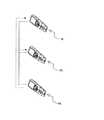
ここで、本実施形態の生体試料測定システムでは、図8に示すように、生体試料データ管理装置1の代わりにクレードル30を介して、生体試料測定装置2,3,4間において設定値の変更情報を送受信する点で、上記実施形態1とは異なっている。
なお、本実施形態において、上記実施形態1と同様の機能を有する構成については、同じ符号を付し、その説明を省略する。
具体的には、本実施形態の生体試料測定システムでは、まず、所定の端末(生体試料測定装置2)の設定データなどをクレードル30に送信する。
また、 クレードル30が所定の生体試料測定装置2の設定データなどを受信するタイミングとしては、以下の3通りが可能である。
・所定の生体試料測定装置2の操作ボタンを押すことにより起動する方法(なお、この場合は、生体試料測定装置2をクレードル30に装填していても、装填していなくてもよい。)
・生体試料測定装置2をクレードル30に装填した時点で、自動的にクレードル30に搭載されている端末設定データなどを格納するメモリに送る方法
・クレードル30に「送受信ボタン」を設けて、その「送受信ボタン」を押すことにより、所定の端末(生体情報測定装置2)の設定データなどをクレードル30に受信し、その内部のメモリに格納する方法
・生体試料測定装置3,4の操作ボタンを押すことにより起動する方法(なお、この場合は、生体試料測定装置3,4をクレードル30に装填していても装填していなくてもよい。)
・生体試料測定装置3,4をクレードル30に装填した時点で自動的にクレードル30のメモリに格納されている設定データなどを生体試料測定装置3,4に送る方法
・クレードル30に「送受信ボタン」を設けて、その「送受信ボタン」を押すことにより、クレードル30のメモリ内の設定データなどを生体試料測定装置3,4へ送信する方法(なお、上記クレードル30に設けられた「送受信ボタン」は、「送信ボタン」と「受信ボタン」とに分離されていてもよい。)
また、クレードル30側では、通信接続された端末がどの端末(生体試料測定装置2,3,4)であるかどうかの確認も各端末の固有の識別コードである「端末ID」/「端末番号」などを使って判断すればよい。
ここで、本実施形態の生体試料測定システムに含まれるクレードル30は、図9に示すように、充電部31と、クレードル制御部32と、メモリ33と、データ送受信部34と、表示部35と、送受信ボタン36と、を有している。
クレードル制御部32は、クレードル30側の制御を行ない、充電制御・設定データの送受信・送受信ボタン36など入力部のスキャン・メモリ33へのデータ記録・再生、および表示部35への表示指令などを行なう。
データ送受信部34は、各生体試料測定装置2,3,4のデータ送受信部14との間において、設定データ等の送受信を行なう。
表示部35は、LCD(Liquid Crystal Display)等のディスプレイを有していてもよい。また、表示部35は、充電状態、通信状態、および設定データの有無・更新等を表示する。また、充電状態、通信状態、設定データの更新状態を、LED(複数)の点灯/点滅などにより表示する。
送受信ボタン36は、各生体試料測定装置2,3,4とクレードル30との間におけるデータ通信を起動する際に使用される。
本実施形態の生体試料測定システムでは、図10および図11に示す手順に従って、生体試料測定装置2,3,4の設定値を共有化する。
すなわち、図10は、クレードル30の送受信ボタン36を操作することで起動する方式において、生体試料測定装置2の設定データをクレードル30に送信して保存されるまでの流れを示すフローチャートである。
まず、測定者によって手動で設定変更される生体試料測定装置2では、入力部9を介して設定値の入力・変更が行なわれる(S31)。
この場合、生体試料測定装置2は、必ずしもクレードル30に装填しておく必要はない。また、生体試料測定装置2側の起動も、入力部9の起動ボタンを操作して通信接続を起動する方法でも、設定値入力操作完了時に自動的に送信状態に移行して通信接続を行なう方法でもよい。
次に、生体試料測定装置2からクレードル30に対して、変更後の設定値に関するデータを送信する(S34)。
一方、クレードル30側では、送受信ボタン36(または受信ボタン36a)が操作されるまで待機し、操作されると(S35)、生体試料測定装置2と接続される(S36)。
次に、クレードル30は、生体試料測定装置2から受信した設定値に関する情報を内部のメモリ33へ保存する(S39)。
そして、図11は、生体試料測定装置2から設定値に関する情報を受信したクレードル30から送信された変更後の設定値に関する情報が、他の端末(生体試料測定装置3,4)において受信、保存されるまでの流れを示すフローチャートである。
まず、生体試料測定装置3,4の電源がONされると(S41)、パスワードが入力される(S42)。なお、パスワード入力の代わりに、バーコードリーダ11によってID等を読み取ってもよい。
次に、生体試料測定装置3,4は、クレードル30との通信接続が可能な状態となり、クレードル30から変更後の設定値に関する情報を受信する(S44)。
次に、生体試料測定装置3,4では、受信した設定値に関する情報を、動作設定メモリ13に保存する(S45)。
次に、クレードル30側では、送受信ボタン36(または、送信ボタン36b)が押下されるまで待機し、実際に押下されると(S47)、生体試料測定装置3,4からの受信要求待ちの状態となる(S48)。
本実施形態の生体試料測定システムでは、各生体試料測定装置2,3,4の充電を行なうクレードル30を介して、生体試料測定装置2における変更後の設定値に関する情報を、他の生体試料測定装置3,4間において共有化する。
これにより、上記と同様に、複数の生体試料測定装置2,3,4を含む生体試料測定システムにおいて、マスター側の生体試料測定装置2において手動で設定するだけで、他の生体試料測定装置3,4においても生体試料測定装置2と共通の設定値を設定することができる。
本発明のさらに他の実施形態に係る生体試料測定システムについて、以下で説明する。
ここで、本実施形態の生体試料測定システムでは、図15に示すように、各生体試料測定装置2,3,4がセットされるクレードル131,132,133間において設定値の変更情報を送受信する点で、上記実施形態1とは異なっている。
なお、本実施形態において、上記実施形態1と同様の機能を有する構成については、同じ符号を付し、その説明を省略する。
なお、上述した実施形態2では、端末(生体試料測定装置)のみで設定データの送受信を実施していたのに対して、本実施形態では、それぞれの端末(生体試料測定装置2,3,4)が装填されているクレードル131,132,133間において設定データの送受信を行なう点で異なっている。
本実施形態では、各クレードル131,132,133は、各端末(生体試料測定装置2,3,4)に対応して設けられている。
また、図15では、各クレードル131,132,133に、それぞれ生体試料測定装置2,3,4が装填されている状態を示しているが、必ずしも全部の生体試料測定装置2,3,4がクレードル131,132,133に装填されている必要は無い。よって、必要に応じて、各生体試料測定装置2,3,4を対応するクレードル131,132,133に装填して、設定値を更新することができる。
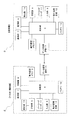
図16は、本実施形態の生体試料測定システムに含まれるクレードル131,132の構成を示すブロック図である。
ただし、本実施形態では、クレードル131,132,133同士の間で設定値の送受信を行なうため、図16に示すように、各クレードル131,132等に設けられたデータ送受信部34Aと34Bを介して行なう。
ここでは、本実施形態のクレードル131(マスタークレードル)に格納されている端末(生体試料測定装置2) の設定値をクレードル132に送信する場合について説明する。
まず、クレードル131側では、生体試料測定装置2の設定値をクレードル131のメモリ33Aに保存する(S71)(なお、設定値をメモリ33Aに取り込む方法としては、上記実施形態3のフローチャート(図10)を参照。)。
なお、クレードル131に生体試料測定装置2が装填されている場合は、クレードル131の送受信ボタン36Aを押下する代わりに、生体試料測定装置2の操作ボタンを押下すればよい。
ここで、通信接続を確認すると、クレードル131からクレードル132に対して設定値に関する情報を送信する(S75)。
一方、クレードル132側では、クレードル131の「送信要求」があったことを確認すると(S76)、通信接続確立して、受信状態となる(S77)。
次に、クレードル132では、受信した設定値に関する情報を内部のメモリ33Bに保存する(S79)。
次に、クレードル132に生体試料測定装置3が装填されているか否かを確認し(S80)、装填されていない場合は終了処理を行う(S80)。
以上、本発明の一実施形態について説明したが、本発明は上記実施形態に限定されるものではなく、発明の要旨を逸脱しない範囲で種々の変更が可能である。
(A)
上記実施形態では、生体試料測定装置2の設定値を手動で変更し、他の生体試料測定装置3,4の設定値を自動的に行なう例を挙げて説明した。しかし、本発明はこれに限定されるものではない。
また、本発明の生体試料測定システムに含まれる生体試料測定装置の台数としては、上述した3台に限らず、2台以上であれば何台であってもよい。
上記実施形態では、生体試料測定装置2,3,4において設定変更されるパラメータとして、ビープ音の音量と表示部7の輝度とを例として挙げて説明した。しかし、本発明はこれに限定されるものではない。
例えば、上述のビープ音の種類には、測定完了時の音、測定エラーを示す警告音、予めスケジュールされている測定実施の時刻を示すアラーム音などがあるが、もちろんこれに限られることは無く、メロディー音でも、音声による通知でもよい。
つまり、この時間帯は、多くの看護師が多くの血糖測定装置を使用することになる。また、その際には看護師IDや患者IDも同時に管理するために、看護師IDおよび患者IDの入力設定は「入力する」に選択され、測定前にそれらのID情報を同時に取得し、正確な管理に用いられる。
このような状況に対応するため、1日のうちに患者IDや看護師IDの入力設定を選択・変更する必要が出てくる場合があり、そのような場合にも、本発明の生体試料測定装置を活用することができる。これにより、看護師への負担も軽減して、設定ミスなどの問題も解消することができるため、信頼性を向上させることができる。
上記実施形態3では、生体試料測定装置2とクレードル30との間におけるデータの送受信を、無線あるいは有線等の通信手段を介して行なう例を挙げて説明した。しかし、本発明はこれに限定されるものではない。
例えば、生体試料測定装置2とクレードル30との間のデータの送受信を行なう手段として、データ送受信部14,34の代わりに、図12に示すように、データコネクタ部14a,37を設け、データコネクタ部14a,37を介して、生体試料測定装置2Aとクレードル30Aとの間においてデータの送受信を行なう生体試料測定システムであってもよい。なお、他の生体試料測定装置3A,4Aについても、生体試料測定装置2Aと同様の構成を備えているものとする。また、データコネクタ部14a,37aは、本発明のデータ送受信部の一種に含まれるものとする。
また、この構成では、生体試料測定装置2Aがクレードル30Aに装填されたことをデータコネクタ部37で検知することで、生体試料測定装置2からクレードル30Aに対して設定データを自動的に送受信することができる。よって、上記実施形態3で説明した「送受信ボタン36」は必ずしも必要ではない。
ここで、図13および図14は、図12に示す生体試料測定システムによる各生体試料測定装置の設定変更の手順を示すフローチャートである。
なお、ここでは、クレードル30Aに生体試料測定装置2Aを装填することにより、自動で起動する方式を採用した場合の流れを示している。
次に、生体試料測定装置2Aをクレードル30Aに装填すると(S52)、クレードル30Aのデータコネクタ部37と生体試料測定装置2Aのデータコネクタ部14aとの接続が完了する(S53)。
次に、生体試料測定装置2Aをクレードル30Aから取り外し(S55)、処理を終了する。
一方、クレードル30A側では、まず、データコネクタ部37における接続確認(生体試料測定装置2Aが装填されたことの検知)を行なう(S56)。
次に、クレードル30Aは、受信した設定値を内部のメモリ33に保存する(S58)。
次に、データコネクタ部37における切離し確認(生体試料測定装置2Aがクレードル30Aから取り外されたことの検知)を行ない(S59)、処理を終了する。
次に、生体試料測定装置3A,4Aは、データコネクタ部14a経由で、設定値に関する情報を受信する(S63)。
次に、生体試料測定装置3A,4Aをクレードル30Aから取り外し(S65)、処理が終了する。
一方、クレードル30A側では、データコネクタ部37において、生体試料測定装置3A,4Aとの接続確認を行なう(S66)。
次に、データコネクタ部37において、生体試料測定装置3A,4Aがクレードル30Aから取り外されたことを確認すると(S68)、処理が終了する。
2,2A 生体試料測定装置(第1の生体試料測定装置)
3,3A,4、4A 生体試料測定装置(第2の生体試料測定装置)
5 測定部
6 制御部
7 表示部
8 記録部(記録部)
9 入力部
10 バッテリ
11 バーコードリーダ
12 動作音発生部
13 動作設定メモリ(記録部)
14 データ送受信部
14a データコネクタ部
15 検出部
16 データ送受信部
17 制御部
18 表示部
19 記録部
20 入力部
30、30A クレードル
31 充電部
32 クレードル制御部
33 メモリ
34 データ送受信部
34A,34B データ送受信部
35 表示部
36 送受信ボタン
36a 受信ボタン
36b 送信ボタン
37 データコネクタ部
131,132,133 クレードル
Claims (12)
- 生体試料の測定を行なう第1・第2の生体試料測定装置を、
備えており、
前記第1・第2の生体試料測定装置は、それぞれ、
前記生体試料の測定を行なう測定部と、
前記測定部に接続された制御部と、
前記制御部に接続されており、前記測定部における測定結果および設定値を表示する表示部と、
前記測定結果および前記設定値を保存する記録部と、
前記設定値を入力する入力部と、
前記設定値に関する情報を送受信するデータ送受信部と、
を有し、
前記第1の生体試料測定装置では、前記制御部が、前記入力部を介して設定変更された設定値に関する情報を、前記データ送受信部を介して前記第2の生体試料測定装置に伝達するとともに、
前記第2の生体試料測定装置では、前記第1の生体試料測定装置から伝達された設定値に関する情報に基づいて、前記制御部が設定値の変更を行なう、
生体試料測定システム。 - 前記設定値には、前記表示部の輝度が含まれる、
請求項1に記載の生体試料測定システム。 - 前記入力部を操作した際にビープ音を発生させる動作音発生部を、さらに備えており、
前記設定値には、前記ビープ音の音量が含まれる、
請求項1に記載の生体試料測定システム。 - 前記第1・第2の生体試料測定装置の前記データ送受信部との間で前記設定値に関する情報を送受信する生体試料データ管理装置を、さらに備えており、
前記第1の生体試料測定装置から前記第2の生体試料測定装置に対して送信される前記設定値に関する情報は、前記生体試料データ管理装置を介して送受信される、
請求項1から3のいずれか1つに記載の生体試料測定システム。 - 前記第1・第2の生体試料測定装置がそれぞれセットされ、前記第1・第2の生体試料測定装置の充電を行なうとともに、前記第1・第2の生体試料測定装置との間で前記設定値に関する情報の送受信を行なう送受信部を有するクレードルを、さらに備えており、
前記クレードルは、前記送受信部を介して、前記第1の生体試料測定装置から前記第2の生体試料測定装置に対して、前記設定値に関する情報を送信する、
請求項1から3のいずれか1項に記載の生体試料測定システム。 - 前記設定値を保存する前記記録部は、EEPROM(Electrically Erasable Programmable Read-Only Memory)によって構成されている、
請求項1に記載の生体試料測定システム。 - 前記クレードルは、設定値データを格納するメモリを有する、
請求項5に記載の生体試料測定システム。 - 前記クレードルは、通信状態、充電状態および設定値更新状態を示す表示部を有する、
請求項5に記載の生体試料測定システム。 - 前記クレードルは、通信を開始する送受信ボタンを有する、
請求項5に記載の生体試料測定システム。 - 前記クレードルは、前記生体試料測定装置と直接データの授受を行なうデータコネクタ部を有する、
請求項5に記載の生体試料測定システム。 - 前記生体試料測定装置は、前記クレードルと直接データの授受を行なうデータコネクタ部を有する、
請求項5に記載の生体試料測定システム。 - 前記生体試料測定装置は、機器の識別コードを内部に有する、
請求項1または5に記載の生体試料測定システム。
Priority Applications (3)
| Application Number | Priority Date | Filing Date | Title |
|---|---|---|---|
| US13/822,096 US20130173176A1 (en) | 2010-09-16 | 2011-09-08 | Biological sample measurement system |
| JP2012533852A JP5809151B2 (ja) | 2010-09-16 | 2011-09-08 | 生体試料測定システム |
| EP11824745.1A EP2618155A4 (en) | 2010-09-16 | 2011-09-08 | SYSTEM FOR MEASURING BIOLOGICAL SAMPLES |
Applications Claiming Priority (2)
| Application Number | Priority Date | Filing Date | Title |
|---|---|---|---|
| JP2010207497 | 2010-09-16 | ||
| JP2010-207497 | 2010-09-16 |
Publications (1)
| Publication Number | Publication Date |
|---|---|
| WO2012035726A1 true WO2012035726A1 (ja) | 2012-03-22 |
Family
ID=45831220
Family Applications (1)
| Application Number | Title | Priority Date | Filing Date |
|---|---|---|---|
| PCT/JP2011/005047 Ceased WO2012035726A1 (ja) | 2010-09-16 | 2011-09-08 | 生体試料測定システム |
Country Status (4)
| Country | Link |
|---|---|
| US (1) | US20130173176A1 (ja) |
| EP (1) | EP2618155A4 (ja) |
| JP (2) | JP5809151B2 (ja) |
| WO (1) | WO2012035726A1 (ja) |
Cited By (1)
| Publication number | Priority date | Publication date | Assignee | Title |
|---|---|---|---|---|
| EP2645101A3 (en) * | 2012-03-30 | 2013-11-06 | Arkray, Inc. | Test strip reader |
Families Citing this family (3)
| Publication number | Priority date | Publication date | Assignee | Title |
|---|---|---|---|---|
| US20080177154A1 (en) * | 2001-08-13 | 2008-07-24 | Novo Nordisk A/S | Portable Device and Method Of Communicating Medical Data Information |
| JPWO2012127870A1 (ja) * | 2011-03-23 | 2014-07-24 | パナソニックヘルスケア株式会社 | 生体情報測定装置 |
| CN109543961A (zh) * | 2018-11-02 | 2019-03-29 | 中国电力科学研究院有限公司 | 一种基于标识信息的绝缘子样品管理方法 |
Citations (7)
| Publication number | Priority date | Publication date | Assignee | Title |
|---|---|---|---|---|
| JPH03111449U (ja) * | 1990-02-26 | 1991-11-14 | ||
| JP2002002913A (ja) | 2000-06-16 | 2002-01-09 | Yamato Transport Co Ltd | 物品配送情報管理システム |
| JP2004113805A (ja) * | 2003-10-07 | 2004-04-15 | Olympus Corp | 手術システムの制御方法 |
| JP2004345840A (ja) * | 2003-05-26 | 2004-12-09 | Murata Mach Ltd | 繊維機械の糸処理条件設定システム |
| JP2005099061A (ja) * | 2005-01-13 | 2005-04-14 | Arkray Inc | 検体検査方法、および検体検査システム |
| WO2008075635A1 (ja) * | 2006-12-19 | 2008-06-26 | Panasonic Corporation | 撮像装置および撮像システム |
| WO2009081790A1 (ja) * | 2007-12-20 | 2009-07-02 | Terumo Kabushiki Kaisha | 血糖測定値管理システム及び血糖値測定装置 |
Family Cites Families (11)
| Publication number | Priority date | Publication date | Assignee | Title |
|---|---|---|---|---|
| US5719761A (en) * | 1993-01-15 | 1998-02-17 | Alaris Medical Systems, Inc. | Configuration control system for configuring multiple biomedical devices |
| CN1289028C (zh) * | 2001-06-29 | 2006-12-13 | 伊西康公司 | 用于评估泌尿功能的系统 |
| US20030093503A1 (en) * | 2001-09-05 | 2003-05-15 | Olympus Optical Co., Ltd. | System for controling medical instruments |
| US7972279B2 (en) * | 2005-01-27 | 2011-07-05 | Instrumentation Laboratory Company | Method and system for managing patient data |
| US20070093786A1 (en) * | 2005-08-16 | 2007-04-26 | Medtronic Minimed, Inc. | Watch controller for a medical device |
| JP2007099061A (ja) * | 2005-10-04 | 2007-04-19 | Bridgestone Corp | 空気入りラジアルタイヤ |
| EP2529784B1 (en) * | 2006-03-23 | 2019-05-01 | Becton, Dickinson and Company | Method for improved diabetes data management and use employing wireless connectivity between patients and healthcare providers and repository of diabetes management information |
| US8770482B2 (en) * | 2006-04-26 | 2014-07-08 | Roche Diagnostics Operations, Inc. | Apparatus and method to administer and manage an intelligent base unit for a handheld medical device |
| JP2007322325A (ja) * | 2006-06-02 | 2007-12-13 | Olympus Corp | 自動分析装置、自動分析装置の分析パラメータ入力方法、および分析パラメータ入力用プログラム |
| CN102519945A (zh) * | 2007-11-19 | 2012-06-27 | 泰尔茂株式会社 | 血糖值测量系统 |
| JP5043810B2 (ja) * | 2007-12-26 | 2012-10-10 | パナソニック株式会社 | 生体試料測定装置およびこれを備えた生体試料測定システム |
-
2011
- 2011-09-08 EP EP11824745.1A patent/EP2618155A4/en not_active Withdrawn
- 2011-09-08 US US13/822,096 patent/US20130173176A1/en not_active Abandoned
- 2011-09-08 WO PCT/JP2011/005047 patent/WO2012035726A1/ja not_active Ceased
- 2011-09-08 JP JP2012533852A patent/JP5809151B2/ja active Active
-
2015
- 2015-09-10 JP JP2015178467A patent/JP5968512B2/ja active Active
Patent Citations (7)
| Publication number | Priority date | Publication date | Assignee | Title |
|---|---|---|---|---|
| JPH03111449U (ja) * | 1990-02-26 | 1991-11-14 | ||
| JP2002002913A (ja) | 2000-06-16 | 2002-01-09 | Yamato Transport Co Ltd | 物品配送情報管理システム |
| JP2004345840A (ja) * | 2003-05-26 | 2004-12-09 | Murata Mach Ltd | 繊維機械の糸処理条件設定システム |
| JP2004113805A (ja) * | 2003-10-07 | 2004-04-15 | Olympus Corp | 手術システムの制御方法 |
| JP2005099061A (ja) * | 2005-01-13 | 2005-04-14 | Arkray Inc | 検体検査方法、および検体検査システム |
| WO2008075635A1 (ja) * | 2006-12-19 | 2008-06-26 | Panasonic Corporation | 撮像装置および撮像システム |
| WO2009081790A1 (ja) * | 2007-12-20 | 2009-07-02 | Terumo Kabushiki Kaisha | 血糖測定値管理システム及び血糖値測定装置 |
Non-Patent Citations (1)
| Title |
|---|
| See also references of EP2618155A4 |
Cited By (1)
| Publication number | Priority date | Publication date | Assignee | Title |
|---|---|---|---|---|
| EP2645101A3 (en) * | 2012-03-30 | 2013-11-06 | Arkray, Inc. | Test strip reader |
Also Published As
| Publication number | Publication date |
|---|---|
| JP5968512B2 (ja) | 2016-08-10 |
| JPWO2012035726A1 (ja) | 2014-01-20 |
| EP2618155A4 (en) | 2016-01-27 |
| EP2618155A1 (en) | 2013-07-24 |
| JP2016026349A (ja) | 2016-02-12 |
| US20130173176A1 (en) | 2013-07-04 |
| JP5809151B2 (ja) | 2015-11-10 |
Similar Documents
| Publication | Publication Date | Title |
|---|---|---|
| US20140343967A1 (en) | Methods to Improve Workflow by Automatically Adding Patient Identification | |
| EP2590385B1 (en) | Wireless obtaining method for external data, electronic apparatus and application program | |
| JP5968512B2 (ja) | 生体試料測定システム | |
| JP2008545512A (ja) | データ収集システムおよびインタフェース | |
| CN102369031A (zh) | 用于血糖控制的医疗设备和方法 | |
| CN102369032A (zh) | 用于提供用于血糖控制的信息的医疗系统和方法 | |
| EP3189774B1 (en) | Medical sensor as well as using method therefor and operating device thereof | |
| US20170231496A1 (en) | Wireless blood pressure measuring techniques | |
| JP2016122426A (ja) | 情報処理装置、および情報処理装置の制御方法 | |
| JP2018005338A (ja) | センサ | |
| JP6891956B2 (ja) | テレメトリシステム | |
| JP5048434B2 (ja) | 看護業務管理システム | |
| US20130082821A1 (en) | Proximity-based glucose meter function activation | |
| JP2014179973A (ja) | 医療用の測定装置、および測定システム | |
| JP2018000316A (ja) | 中継装置 | |
| US20250160643A1 (en) | Measurement device, information terminal, and operation recording medium of information terminal | |
| JP6249640B2 (ja) | 医療用外出通知システム、受信機および医療用外出通知プログラム | |
| JP2020534097A (ja) | 植え込み型医療機器のための遠隔測定通信システム | |
| WO2024057610A1 (ja) | 測定装置、及び制御プログラム | |
| JP2024044701A (ja) | 測定装置、情報端末、及び情報端末の作動プログラム | |
| EP2645101A2 (en) | Test strip reader | |
| JP2016182249A (ja) | 情報管理装置及び情報管理システム | |
| JP2001321344A (ja) | 体調データ記録装置 | |
| EP4550343A1 (en) | Medical device data interconnectivity in a healthcare network | |
| JP2015018461A (ja) | 設定端末および病院内情報表示システム |
Legal Events
| Date | Code | Title | Description |
|---|---|---|---|
| 121 | Ep: the epo has been informed by wipo that ep was designated in this application |
Ref document number: 11824745 Country of ref document: EP Kind code of ref document: A1 |
|
| ENP | Entry into the national phase |
Ref document number: 2012533852 Country of ref document: JP Kind code of ref document: A |
|
| REEP | Request for entry into the european phase |
Ref document number: 2011824745 Country of ref document: EP |
|
| WWE | Wipo information: entry into national phase |
Ref document number: 2011824745 Country of ref document: EP |
|
| WWE | Wipo information: entry into national phase |
Ref document number: 13822096 Country of ref document: US |
|
| NENP | Non-entry into the national phase |
Ref country code: DE |