WO2012036141A1 - ロータリ型圧縮機 - Google Patents
ロータリ型圧縮機 Download PDFInfo
- Publication number
- WO2012036141A1 WO2012036141A1 PCT/JP2011/070787 JP2011070787W WO2012036141A1 WO 2012036141 A1 WO2012036141 A1 WO 2012036141A1 JP 2011070787 W JP2011070787 W JP 2011070787W WO 2012036141 A1 WO2012036141 A1 WO 2012036141A1
- Authority
- WO
- WIPO (PCT)
- Prior art keywords
- synthetic resin
- resin coating
- cylinder
- rotor
- rotary compressor
- Prior art date
- Legal status (The legal status is an assumption and is not a legal conclusion. Google has not performed a legal analysis and makes no representation as to the accuracy of the status listed.)
- Ceased
Links
Images







Classifications
-
- F—MECHANICAL ENGINEERING; LIGHTING; HEATING; WEAPONS; BLASTING
- F04—POSITIVE - DISPLACEMENT MACHINES FOR LIQUIDS; PUMPS FOR LIQUIDS OR ELASTIC FLUIDS
- F04C—ROTARY-PISTON, OR OSCILLATING-PISTON, POSITIVE-DISPLACEMENT MACHINES FOR LIQUIDS; ROTARY-PISTON, OR OSCILLATING-PISTON, POSITIVE-DISPLACEMENT PUMPS
- F04C29/00—Component parts, details or accessories of pumps or pumping installations, not provided for in groups F04C18/00 - F04C28/00
-
- F—MECHANICAL ENGINEERING; LIGHTING; HEATING; WEAPONS; BLASTING
- F04—POSITIVE - DISPLACEMENT MACHINES FOR LIQUIDS; PUMPS FOR LIQUIDS OR ELASTIC FLUIDS
- F04C—ROTARY-PISTON, OR OSCILLATING-PISTON, POSITIVE-DISPLACEMENT MACHINES FOR LIQUIDS; ROTARY-PISTON, OR OSCILLATING-PISTON, POSITIVE-DISPLACEMENT PUMPS
- F04C18/00—Rotary-piston pumps specially adapted for elastic fluids
-
- F—MECHANICAL ENGINEERING; LIGHTING; HEATING; WEAPONS; BLASTING
- F01—MACHINES OR ENGINES IN GENERAL; ENGINE PLANTS IN GENERAL; STEAM ENGINES
- F01C—ROTARY-PISTON OR OSCILLATING-PISTON MACHINES OR ENGINES
- F01C21/00—Component parts, details or accessories not provided for in groups F01C1/00 - F01C20/00
- F01C21/10—Outer members for co-operation with rotary pistons; Casings
- F01C21/104—Stators; Members defining the outer boundaries of the working chamber
- F01C21/108—Stators; Members defining the outer boundaries of the working chamber with an axial surface, e.g. side plates
-
- F—MECHANICAL ENGINEERING; LIGHTING; HEATING; WEAPONS; BLASTING
- F04—POSITIVE - DISPLACEMENT MACHINES FOR LIQUIDS; PUMPS FOR LIQUIDS OR ELASTIC FLUIDS
- F04C—ROTARY-PISTON, OR OSCILLATING-PISTON, POSITIVE-DISPLACEMENT MACHINES FOR LIQUIDS; ROTARY-PISTON, OR OSCILLATING-PISTON, POSITIVE-DISPLACEMENT PUMPS
- F04C18/00—Rotary-piston pumps specially adapted for elastic fluids
- F04C18/30—Rotary-piston pumps specially adapted for elastic fluids having the characteristics covered by two or more of groups F04C18/02, F04C18/08, F04C18/22, F04C18/24, F04C18/48, or having the characteristics covered by one of these groups together with some other type of movement between co-operating members
- F04C18/34—Rotary-piston pumps specially adapted for elastic fluids having the characteristics covered by two or more of groups F04C18/02, F04C18/08, F04C18/22, F04C18/24, F04C18/48, or having the characteristics covered by one of these groups together with some other type of movement between co-operating members having the movement defined in group F04C18/08 or F04C18/22 and relative reciprocation between the co-operating members
- F04C18/344—Rotary-piston pumps specially adapted for elastic fluids having the characteristics covered by two or more of groups F04C18/02, F04C18/08, F04C18/22, F04C18/24, F04C18/48, or having the characteristics covered by one of these groups together with some other type of movement between co-operating members having the movement defined in group F04C18/08 or F04C18/22 and relative reciprocation between the co-operating members with vanes reciprocating with respect to the inner member
-
- F—MECHANICAL ENGINEERING; LIGHTING; HEATING; WEAPONS; BLASTING
- F04—POSITIVE - DISPLACEMENT MACHINES FOR LIQUIDS; PUMPS FOR LIQUIDS OR ELASTIC FLUIDS
- F04C—ROTARY-PISTON, OR OSCILLATING-PISTON, POSITIVE-DISPLACEMENT MACHINES FOR LIQUIDS; ROTARY-PISTON, OR OSCILLATING-PISTON, POSITIVE-DISPLACEMENT PUMPS
- F04C18/00—Rotary-piston pumps specially adapted for elastic fluids
- F04C18/30—Rotary-piston pumps specially adapted for elastic fluids having the characteristics covered by two or more of groups F04C18/02, F04C18/08, F04C18/22, F04C18/24, F04C18/48, or having the characteristics covered by one of these groups together with some other type of movement between co-operating members
- F04C18/34—Rotary-piston pumps specially adapted for elastic fluids having the characteristics covered by two or more of groups F04C18/02, F04C18/08, F04C18/22, F04C18/24, F04C18/48, or having the characteristics covered by one of these groups together with some other type of movement between co-operating members having the movement defined in group F04C18/08 or F04C18/22 and relative reciprocation between the co-operating members
- F04C18/344—Rotary-piston pumps specially adapted for elastic fluids having the characteristics covered by two or more of groups F04C18/02, F04C18/08, F04C18/22, F04C18/24, F04C18/48, or having the characteristics covered by one of these groups together with some other type of movement between co-operating members having the movement defined in group F04C18/08 or F04C18/22 and relative reciprocation between the co-operating members with vanes reciprocating with respect to the inner member
- F04C18/3441—Rotary-piston pumps specially adapted for elastic fluids having the characteristics covered by two or more of groups F04C18/02, F04C18/08, F04C18/22, F04C18/24, F04C18/48, or having the characteristics covered by one of these groups together with some other type of movement between co-operating members having the movement defined in group F04C18/08 or F04C18/22 and relative reciprocation between the co-operating members with vanes reciprocating with respect to the inner member the inner and outer member being in contact along one line or continuous surface substantially parallel to the axis of rotation
-
- F—MECHANICAL ENGINEERING; LIGHTING; HEATING; WEAPONS; BLASTING
- F04—POSITIVE - DISPLACEMENT MACHINES FOR LIQUIDS; PUMPS FOR LIQUIDS OR ELASTIC FLUIDS
- F04C—ROTARY-PISTON, OR OSCILLATING-PISTON, POSITIVE-DISPLACEMENT MACHINES FOR LIQUIDS; ROTARY-PISTON, OR OSCILLATING-PISTON, POSITIVE-DISPLACEMENT PUMPS
- F04C18/00—Rotary-piston pumps specially adapted for elastic fluids
- F04C18/30—Rotary-piston pumps specially adapted for elastic fluids having the characteristics covered by two or more of groups F04C18/02, F04C18/08, F04C18/22, F04C18/24, F04C18/48, or having the characteristics covered by one of these groups together with some other type of movement between co-operating members
- F04C18/34—Rotary-piston pumps specially adapted for elastic fluids having the characteristics covered by two or more of groups F04C18/02, F04C18/08, F04C18/22, F04C18/24, F04C18/48, or having the characteristics covered by one of these groups together with some other type of movement between co-operating members having the movement defined in group F04C18/08 or F04C18/22 and relative reciprocation between the co-operating members
- F04C18/356—Rotary-piston pumps specially adapted for elastic fluids having the characteristics covered by two or more of groups F04C18/02, F04C18/08, F04C18/22, F04C18/24, F04C18/48, or having the characteristics covered by one of these groups together with some other type of movement between co-operating members having the movement defined in group F04C18/08 or F04C18/22 and relative reciprocation between the co-operating members with vanes reciprocating with respect to the outer member
- F04C18/3562—Rotary-piston pumps specially adapted for elastic fluids having the characteristics covered by two or more of groups F04C18/02, F04C18/08, F04C18/22, F04C18/24, F04C18/48, or having the characteristics covered by one of these groups together with some other type of movement between co-operating members having the movement defined in group F04C18/08 or F04C18/22 and relative reciprocation between the co-operating members with vanes reciprocating with respect to the outer member the inner and outer member being in contact along one line or continuous surfaces substantially parallel to the axis of rotation
- F04C18/3564—Rotary-piston pumps specially adapted for elastic fluids having the characteristics covered by two or more of groups F04C18/02, F04C18/08, F04C18/22, F04C18/24, F04C18/48, or having the characteristics covered by one of these groups together with some other type of movement between co-operating members having the movement defined in group F04C18/08 or F04C18/22 and relative reciprocation between the co-operating members with vanes reciprocating with respect to the outer member the inner and outer member being in contact along one line or continuous surfaces substantially parallel to the axis of rotation the surfaces of the inner and outer member, forming the working space, being surfaces of revolution
-
- F—MECHANICAL ENGINEERING; LIGHTING; HEATING; WEAPONS; BLASTING
- F04—POSITIVE - DISPLACEMENT MACHINES FOR LIQUIDS; PUMPS FOR LIQUIDS OR ELASTIC FLUIDS
- F04C—ROTARY-PISTON, OR OSCILLATING-PISTON, POSITIVE-DISPLACEMENT MACHINES FOR LIQUIDS; ROTARY-PISTON, OR OSCILLATING-PISTON, POSITIVE-DISPLACEMENT PUMPS
- F04C23/00—Combinations of two or more pumps, each being of rotary-piston or oscillating-piston type, specially adapted for elastic fluids; Pumping installations specially adapted for elastic fluids; Multi-stage pumps specially adapted for elastic fluids
- F04C23/001—Combinations of two or more pumps, each being of rotary-piston or oscillating-piston type, specially adapted for elastic fluids; Pumping installations specially adapted for elastic fluids; Multi-stage pumps specially adapted for elastic fluids of similar working principle
-
- F—MECHANICAL ENGINEERING; LIGHTING; HEATING; WEAPONS; BLASTING
- F04—POSITIVE - DISPLACEMENT MACHINES FOR LIQUIDS; PUMPS FOR LIQUIDS OR ELASTIC FLUIDS
- F04C—ROTARY-PISTON, OR OSCILLATING-PISTON, POSITIVE-DISPLACEMENT MACHINES FOR LIQUIDS; ROTARY-PISTON, OR OSCILLATING-PISTON, POSITIVE-DISPLACEMENT PUMPS
- F04C23/00—Combinations of two or more pumps, each being of rotary-piston or oscillating-piston type, specially adapted for elastic fluids; Pumping installations specially adapted for elastic fluids; Multi-stage pumps specially adapted for elastic fluids
- F04C23/008—Hermetic pumps
-
- F—MECHANICAL ENGINEERING; LIGHTING; HEATING; WEAPONS; BLASTING
- F04—POSITIVE - DISPLACEMENT MACHINES FOR LIQUIDS; PUMPS FOR LIQUIDS OR ELASTIC FLUIDS
- F04C—ROTARY-PISTON, OR OSCILLATING-PISTON, POSITIVE-DISPLACEMENT MACHINES FOR LIQUIDS; ROTARY-PISTON, OR OSCILLATING-PISTON, POSITIVE-DISPLACEMENT PUMPS
- F04C27/00—Sealing arrangements in rotary-piston pumps specially adapted for elastic fluids
- F04C27/008—Sealing arrangements in rotary-piston pumps specially adapted for elastic fluids for other than working fluid, i.e. the sealing arrangements are not between working chambers of the machine
-
- F—MECHANICAL ENGINEERING; LIGHTING; HEATING; WEAPONS; BLASTING
- F04—POSITIVE - DISPLACEMENT MACHINES FOR LIQUIDS; PUMPS FOR LIQUIDS OR ELASTIC FLUIDS
- F04C—ROTARY-PISTON, OR OSCILLATING-PISTON, POSITIVE-DISPLACEMENT MACHINES FOR LIQUIDS; ROTARY-PISTON, OR OSCILLATING-PISTON, POSITIVE-DISPLACEMENT PUMPS
- F04C2230/00—Manufacture
- F04C2230/90—Improving properties of machine parts
- F04C2230/91—Coating
-
- F—MECHANICAL ENGINEERING; LIGHTING; HEATING; WEAPONS; BLASTING
- F04—POSITIVE - DISPLACEMENT MACHINES FOR LIQUIDS; PUMPS FOR LIQUIDS OR ELASTIC FLUIDS
- F04C—ROTARY-PISTON, OR OSCILLATING-PISTON, POSITIVE-DISPLACEMENT MACHINES FOR LIQUIDS; ROTARY-PISTON, OR OSCILLATING-PISTON, POSITIVE-DISPLACEMENT PUMPS
- F04C2240/00—Components
- F04C2240/80—Other components
- F04C2240/802—Liners
-
- F—MECHANICAL ENGINEERING; LIGHTING; HEATING; WEAPONS; BLASTING
- F05—INDEXING SCHEMES RELATING TO ENGINES OR PUMPS IN VARIOUS SUBCLASSES OF CLASSES F01-F04
- F05C—INDEXING SCHEME RELATING TO MATERIALS, MATERIAL PROPERTIES OR MATERIAL CHARACTERISTICS FOR MACHINES, ENGINES OR PUMPS OTHER THAN NON-POSITIVE-DISPLACEMENT MACHINES OR ENGINES
- F05C2253/00—Other material characteristics; Treatment of material
- F05C2253/20—Resin
Definitions
- the present invention relates to a rotary compressor, and more particularly, to a cylindrical cylinder for accommodating a rotatable or swingable rotor, and a pair of closing members for closing the openings at both axial ends of the cylinder.
- the present invention relates to a rotary compressor.
- a cylinder formed in a substantially cylindrical shape, a pair of closing members for closing openings at both axial ends of the cylinder, and a cylinder housed and accommodated in the cylinder and rotated or rocked in conjunction with the drive shaft
- a rotary compressor provided with a rotor is known (for example, Patent Documents 1 to 3).
- the axial dimension of the rotor is set to be slightly smaller than the axial dimension of the cylinder, and when the components of the rotary compressor are completely assembled, the axial direction of the rotor is set. It is intended that a slight gap be secured between the end faces of the and the inner wall surface (thrust surface) of the above-mentioned closing member adjacent to these points.
- Patent No. 3742848 gazette JP-A-57-49084 JP, 2010-133346, A
- the annular notch is formed to have a depth and an outer diameter capable of receiving the outer peripheral edge of the synthetic resin coating, the annular notch and the outer peripheral edge of the synthetic resin coating accommodated therein are provided.
- this has the disadvantage that the compression efficiency when the compressor is activated is poor.
- the outer peripheral edge of the synthetic resin coating is raised more than the inner wall surface (end surface) of the original closing member, and a step is generated. Therefore, in the process of assembling the cylinder and the both closing members, it is first necessary to align the cylinder and the both closing members. At that time, the step which is the outer peripheral edge of the synthetic resin coating may be caught in the annular notch on the cylinder side, which makes the axial alignment operation of the cylinder and the both closing members complicated. Then, the entire area of the outer peripheral edge of the synthetic resin coating is not completely accommodated in the annular notch portion, and a part of the outer peripheral edge of the synthetic resin coating is assembled while being displaced outward from the annular notch portion. May be completed.
- the present invention described in claim 1 comprises a cylindrical cylinder disposed in a casing, a pair of closing members for closing axial front and rear openings in the cylinder, and the cylinder
- a rotary compressor comprising: a compression space formed by a pair of closing members; and a rotor accommodated in the compression space and movable in conjunction with a drive shaft,
- a recess is formed in a region facing the compression space on the inner wall surface of each of the closing members, and a synthetic resin coating is embedded in the recess to form the surface of the synthetic resin coating and the radially outward direction of the closing member. And the original inner wall surface of the same.
- reference numeral 1 denotes a rotary compressor
- this rotary compressor 1 is mainly used for a home or business air conditioner
- FIG. 6 and FIG. 8 are mainly used for a car air conditioner.
- the rotary compressor 1 is disposed at a lower portion in the closed casing 2 and a motor 3 as a drive source stored at the upper portion in the closed casing 2 and rotated by the motor 3 to suck and discharge the refrigerant gas.
- a compression mechanism 4 4
- the compression mechanism 4 has a cylindrical cylinder 5 fitted to the inner surface of the hermetic casing 2 and a cylindrical shape housed in the cylinder 5 such that a part of the outer peripheral surface 6C always contacts the inner peripheral surface 5A of the cylinder 5
- the vane 6 is slidably fitted in the rotor 6 and the guide groove 5B in the radial direction of the cylinder 5, and the tip end portion always contacts the outer peripheral surface 6C of the rotor 6 by the spring 7
- the pair of closing members 11 and 12 are disposed in a state in which the upper and lower end surfaces 5C and 5D of the cylinder 5 are sandwiched from the upper and lower sides, and these cylinders 5 and the both closing members 11 and 12 Airtightness is maintained by the fastening bolts 13 and they are integrally connected.
- the space surrounded by the cylinder 5 and the both closing members 11 and 12 is the compression space 14, and the inner wall surfaces 11A and 12A (thrust surfaces) of the both closing members 11 and 12 facing the compression space 14 are It is in the state close to end faces 6A and 6B of the rotor 6.
- the compression space 14 of the cylinder 5 is divided into two adjacent space portions by the vane 8 and the outer peripheral surface 6C of the rotor 6, one space portion becomes the suction chamber 15, and the other space portion is the compression chamber. It is sixteen.
- Through holes 11B and 12B are bored in the central portions of the upper and lower closing members 11 and 12, and the drive shaft 3A of the motor 3 is penetrated by keeping airtight the through holes 11B and 12B of both closing members 11 and 12 At the same time, the rotor 6 is also penetrated.
- the drive shaft 3A is rotatably supported by the through holes 11B and 12B of the both closing members 11 and 12.
- the drive shaft 3A located in the rotor 6 is a large diameter eccentric portion 3B offset in the radial direction from the axial center of the original drive shaft 3A, and this large diameter eccentric portion 3B corresponds to the rotor 6 It slides in the circumferential direction with the inner circumferential surface of the.
- the large diameter eccentric portion 3B is also rotated, so the rotor 6 is along the inner peripheral surface 5A of the cylinder 5 in conjunction with the rotation of the large diameter eccentric portion 3B. It is supposed to be rotated.
- the lubricating oil 21 is stored in the lower part of the sealed casing 2, and when the rotor 6 is rotated, the rotor 6 is rotated via an oil passage (not shown) formed in the lower end portion of the drive shaft 3A.
- the lubricating oil 21 is supplied to the sliding portion between the inner peripheral surface 6D and the outer peripheral surface 6C.
- the configuration of such a rotary compressor 1 is known, for example, from Patent Document 1.
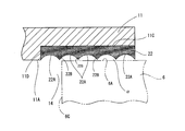
- both the end surfaces 6A and 6B of the rotor 6 and the inner wall surface 11A which is a thrust surface are obtained. It is characterized in that it is configured to suppress the burn-in of 12A. That is, as shown in an enlarged manner in FIGS. 3 to 4, the inner wall surfaces 11A and 12A of both closing members 11 and 12 have an outer peripheral side closer to the fastening bolt 13 from the through holes 11B and 12B on the central side thereof. Circular recesses 11C and 12C with a shallow depth are formed over the area.
- the outer diameters of the recesses 11C and 12C are set to be the same, and the depths of the recesses 11C and 12C are set to the same dimension. Specifically, the depths of the recesses 11C and 12C are set to, for example, 1 ⁇ m to 100 ⁇ m, preferably 5 ⁇ m to 50 ⁇ m.
- the outer peripheral edges 11 D and 12 D of the recessed portions 11 C and 12 C are located radially outward of the inner peripheral surface 5 A of the cylinder 5 And polymerize with the end faces 5C and 5D of the cylinder 5.
- synthetic resin coatings 22 and 22 are applied to the entire area in the recessed portions 11C and 12C of both closing members 11 and 12 with a thickness corresponding to the depth of the recessed portions 11C and 12C.
- the surfaces of the synthetic resin coatings 22 and 22 are flush with the inner wall surfaces 11A and 12A of the original closing members 11 and 12 which are adjacent to the concave portions 11C and 12C.
- annular grooves 22A of the same depth and width are formed concentrically at a predetermined pitch in the radial direction on the surface of the synthetic resin coating 22.
- the width of the annular groove 22A is set to 20 ⁇ m to 500 ⁇ m, preferably 50 ⁇ m to 300 ⁇ m.
- the depth of the annular groove 22A is set to 1 to 20 ⁇ m, preferably to 2 to 10 ⁇ m.
- the material of the synthetic resin coating 22, the thermosetting synthetic resin, is used graphite, carbon, PTFE, a plus at least one of MoS 2.
- a material is used as a synthetic resin coating material, you may add hard substances, such as an alumina, to the material mentioned above further in order to raise the intensity
- the annular groove 22A may be formed not only on the surface of the synthetic resin coating 22 but also on a part or the whole of the inner wall surfaces 11A and 12A on the outer periphery in the radial direction of the synthetic resin coating 22.
- the recessed portions 11C and 12C having shallow depths are formed in the inner wall surfaces 11A and 12A of the closing members 11 and 12, and the insides of the recessed portions 11C and 12C are covered with the synthetic resin coat 22. Filled and coated.
- the synthetic resin coatings 22 and 22 are formed on the recesses 11C and 12C.
- the synthetic resin coating 22 can be embedded in the concave portions 11C and 12C without complicated dimensional control regarding the dimension of the concave portion and the thickness of the synthetic resin coating. .
- the thrust surface is often exposed to the liquid refrigerant due to the liquefaction phenomenon of the refrigerant gas particularly due to the difference in temperature between day and night. Since the liquid refrigerant has the function of cleaning the lubricating oil, when the thrust surface is exposed to the liquid refrigerant, the dry environment becomes lacking in the lubricating oil, and conventionally there is no lubricating oil at the start of the compressor in such a case. The phenomenon of sticking on the thrust surface sometimes occurred.
- the thrust surface is covered with the synthetic resin coating 22, even in the dry environment where the lubricating oil is insufficient, the seizure of the thrust surface, that is, the portion of the synthetic resin coating 22 is prevented. Can. Furthermore, by adding PTFE to the above-described material as the synthetic resin coating 22, it is possible to improve the sliding characteristics of the thrust surface (synthetic resin coating 22) under the above-described dry environment, and under the above-described dry environment. Even higher sliding characteristics can be ensured. In addition, it is possible to use a hard additive such as graphite in the above-mentioned material as the synthetic resin coating 22, thereby making the rigidity of the annular groove 22A of the synthetic resin coating 22 and the annular projection adjacent thereto.
- a hard additive such as graphite
- FIGS. 5 to 6 show the main part of a rotary compressor 1 according to a second embodiment to which the present invention is applied.
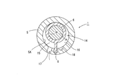
- a vane type rotary compressor 1 is used.
- the present invention is applied. That is, the vane-type rotary compressor 1 includes a cylindrical cylinder 5, a cylindrical rotor 6 accommodated therein and rotated by the drive shaft 3 A of the motor, and an outer peripheral portion of the rotor 6 in the radial direction.
- the three vanes 8 provided and a pair of closing members 11 and 12 for closing the end faces 5C and 5D which are the front and rear openings of the cylinder 5 are provided.
- the cylinder 5 and the both closing members 11 and 12 are airtightly connected by a plurality of fastening bolts 13, and the compression space 14 in the cylinder 5 is formed by the outer peripheral surface of the rotor 6 and the three vanes 8.
- the working chamber 15 is divided.
- the drive shaft 3A disposed coaxially with the rotor 6 is rotated, the rotor 6 is rotated, so that the tips of the three vanes 8 are moved while being in contact with the inner circumferential surface 5A of the cylinder 5,
- One working chamber 15 is to be expanded and contracted.
- the refrigerant gas sucked into the working chamber 15 from the suction port 17 is compressed and then discharged to the outside of the cylinder 5 through the discharge port 18.
- the basic configuration of such a second embodiment is, for example, the same as that of Patent Document 3 described above.
- the recessed parts 11C and 12C similar to 1st Example mentioned above are formed in both the closing members 11 and 12, and these recessed parts 11C,
- a synthetic resin coating 22 is provided in 12C as in the first embodiment described above.
- a large number of annular grooves are formed on the surface of the synthetic resin coating 22 of the second embodiment as in the first embodiment shown in FIG.
- members corresponding to those in the first embodiment are given the same reference numerals. Even with the rotary compressor 1 of the second embodiment configured as described above, the same operation and effect as those of the first embodiment can be obtained.
- the present invention is applied to the rotary compressor 1 in which the cylindrical rotor 6 and the flat plate vane 8 are separated.
- the rotary compressor 1 is provided with a rotor 6 in which the vanes 8 are integrally fixed, and the rotor 6 is oscillated in the cylinder 5 by the drive shaft 3A of the motor and its eccentric large diameter portion 3B.
- the present invention can also be applied.
- the rotary compressor 1 having such a configuration is known from the above-mentioned Patent Document 2, and thus the detailed description is omitted.
- the configuration shown in FIG. 3 can be adopted as a pair of closing members for closing the cylinder 5 of the rotary compressor 1 shown in FIG. 7 and the end surfaces in the axial direction.
- the members corresponding to the first embodiment are given the same reference numerals.
- the inner peripheral surface 5A of the cylinder 5 has a cylindrical shape, and a rotary type in which three vanes 8 are arranged on the outer peripheral surface 6C of the rotor 6
- the present invention is applied to the compressor 1, as shown in FIG. 8, the present invention is applied to the rotary compressor 1 having five vanes 8 on the outer peripheral portion of the rotor 6 and an elliptical cross section of the cylinder 5.
- the invention can be applied.
- the configuration shown in FIG. 3 can be applied as a pair of closing members for closing the cylinder 5 of the rotary compressor 1 shown in FIG. 8 and the end face which is the opening in the axial direction.
- FIG. 3 can be applied as a pair of closing members for closing the cylinder 5 of the rotary compressor 1 shown in FIG. 8 and the end face which is the opening in the axial direction.
- FIG. 9 shows still another embodiment of the present invention.
- the embodiment shown in FIG. 9 is an application of the present invention to a rotary type compression 101 provided with the two stages of the configuration of FIG. 7 above and below. That is, the compression mechanism 104 of the rotary compressor 101 has a first cylinder 105 whose upper opening is closed by the upper closing member 111 fitted in the hermetic casing 102 and the inner wall surface 111A (lower surface) of the closing member 111.
- a disc-like intermediate closing member 120 closing the lower opening of the first cylinder 105, a second cylinder 105 'closing the upper opening by the lower surface of the intermediate closing member 120, and the second cylinder 105
- a lower closure member 112 closing the lower opening of the '.
- a space portion surrounded by the first cylinder 105, the closing member 111 and the intermediate closing member 120 is a first compression space 114, and the first rotor 106 is accommodated therein.
- a first large-diameter eccentric portion 103B of a drive shaft 103A of the motor 103 is slidably fitted in the circumferential direction.
- a space portion surrounded by the intermediate closing member 120, the second cylinder 105 'and the lower closing member 112 is a second compression space 114', and the second rotor 106 'is accommodated therein.
- a second large-diameter eccentric portion 103B 'of the drive shaft 103A is slidably fitted in the second rotor 106'.
- the configuration of such a multistage rotary compressor 101 is known in, for example, Japanese Patent Application Laid-Open No. 2008-280485 and the like, and thus the detailed description thereof will be omitted.
- the structure similar to the said FIG.3 and FIG.4 is employ
- the inner wall surface (lower surface) 111A of the upper closing member 111 and the upper surface 120A (inner wall surface) of the intermediate closing member 120 are provided with the same concave portion as in FIG. 4 and a resin coating filling the same.
- the lower surface 120B (inner wall surface) of the intermediate closing member 120 and the inner wall surface 112A (upper) of the lower closing member 112 are provided with the same recess as in FIG. 4 and a resin coating for filling the same.
- member numbers corresponding to 100 in FIG. 1 and FIG. thus, the configurations of the present invention shown in FIGS. 3 to 4 can be applied to both the closing members 111 and 112 and the middle closing member 120 in the multistage rotary compressor 1.
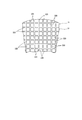
- a large number of recesses are formed by providing a plurality of annular grooves 22A on the surface of the synthetic resin coating 22, but as shown in the front view of the main part in FIG.
- regular rectangular recesses 22D may be formed at positions adjacent to the grid-like protrusions 22C.
- each lattice-like projection 22C is a substantial thrust surface.
- the plurality of annular grooves 22A may be formed concentrically with different pitches, or spiral grooves may be formed instead of the annular grooves.
- the synthetic resin The large number of annular grooves 22A in the surface of the coating 22 may be omitted to make the entire surface of the synthetic resin coating 22 flat.
Landscapes
- Engineering & Computer Science (AREA)
- Mechanical Engineering (AREA)
- General Engineering & Computer Science (AREA)
- Applications Or Details Of Rotary Compressors (AREA)
- Rotary Pumps (AREA)
Abstract
Description
こうした従来のロータリ型圧縮機においては、ローターの軸方向寸法はシリンダの軸方向寸法よりも僅かに短く設定されており、ロータリ型圧縮機の構成部材の組み付け完了時においては、上記ローターの軸方向の両端面と、それらの箇所に近接する上記各閉鎖部材の内壁面(スラスト面)との間に僅かな隙間が確保されるように意図されている。
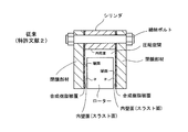
そして、従来のロータリ型圧縮機においては、シリンダ内の圧縮空間に冷媒ガスが吸入・吐出される際に、冷媒ガスとシリンダや閉鎖部材等との間で受熱放熱作用が行われるが、その受熱放熱作用によってロータリ型圧縮機の体積効率が低下するという欠点があった。そこで、例えば特許文献2においては、シリンダ内の圧縮空間に臨む箇所、すなわち、一対の閉鎖部材の内壁面(スラスト面)を合成樹脂によって被覆することが提案されている(図11参照)。そのような構成を採用することで、特許文献2の圧縮機においては、圧縮空間内に給排される冷媒ガスと一対の閉鎖部材の内壁面と間の受熱放熱作用を抑制して、圧縮機の体積効率を向上させるように意図されている。
ところで、上記特許文献2の圧縮機においては、前後一対の閉鎖部材の内壁面である端面全域にわたって合成樹脂被覆が施されているために、次のような問題があった。すなわち、図11に示すように、シリンダにおける軸方向前後の開口部を一対の閉鎖部材で閉鎖して、シリンダと両閉鎖部材を締結ボルトで一体に組み付けた際に、両閉鎖部材の内壁面の合成樹脂被覆が軸方向に圧縮されるので、ローターにおける軸方向の両端面とそれに近接する内壁面(合成樹脂被覆)との間の隙間αが当初意図した程度に確保されない場合がある。このように、組み付け完了後において、ローターの両端面とそれに近接する内壁面(合成樹脂被覆)との隙間が意図した程度に確保されない状態では、その後、ローターが回転された際に、ローターの軸方向の両端面とそれに摺接する内壁面(合成樹脂被覆)に焼付きが生じるという問題がある。
そこで、特許文献3の圧縮機においては、ローターの両端面と両閉鎖部材の内壁面との焼付きを防止するために、シリンダの軸方向の両端面と当接する箇所では、両閉鎖部材の内壁面の合成樹脂被覆を省略している(図12参照)。より詳細には、図12に示すように、特許文献3においては、シリンダの内周面における軸方向の前後の縁部(両方の端面の内周縁)に環状の切欠き部を形成するとともに、両閉鎖部材の合成樹脂被覆の半径方向寸法は、上記環状の切欠き部内に収容される寸法に設定されている。そのように構成することで、図12に示すようにシリンダと両閉鎖部材を締結ボルトで組み付けた際に、切欠き部内に両合成樹脂被覆の外周縁が収容されるので、それらの外周縁が軸方向に圧縮されることはない。そのため、特許文献3の圧縮機においては、組み付け完了後において、ローターの軸方向の両端面と、それらに近接する閉鎖部材の内壁面(スラスト面)との間に僅かな隙間αが確保されるようになっている。
また、上記環状の切欠き部は、合成樹脂被覆の外周縁を収容可能な深さと外径を備えるように形成されるので、環状の切欠き部とそこに収容される合成樹脂被覆の外周縁との間には、半径方向と軸方向において僅かな間隙Xが生じる(図12参照)。このような間隙Xが生じると、組み付け完了後にローターが回転されてシリンダ内の圧縮空間が拡縮される際に、上記間隙Xを介して冷媒ガスが高圧空間から低圧空間側へ漏洩することになり、それによって、圧縮機が作動された際の圧縮効率が悪くなるという欠点がある。
さらに、特許文献3の圧縮機においては、本来の閉鎖部材の内壁面(端面)よりも合成樹脂被覆の外周縁は盛り上がって段差が生じている。そのため、シリンダと両閉鎖部材とを組み付ける過程において、先ず、シリンダと両方の閉鎖部材との軸心合せをする必要がある。その際に、合成樹脂被覆の外周縁である段差がシリンダ側の環状の切欠き部に引っ掛かることがあり、そのために、シリンダと両閉鎖部材の軸心合わせ作業が煩雑になっていた。そして、環状の切欠き部内に合成樹脂被覆の外周縁の全域が完全に収容されずに、合成樹脂被覆の外周縁の一部が環状の切欠き部よりも外方に位置ずれしたままで組み付けが完了する場合もある。この場合には、シリンダ内に吸入・吐出される冷媒ガスの漏れが生じることで圧縮機の性能の低下が生じることになり、さらに、合成樹脂被覆とローターの端面とが摺動する際に異常摩耗が生じて、焼付きが発生するという欠点があった。
上記各閉鎖部材の内壁面における上記圧縮空間に臨む領域に凹部を形成するとともに、該凹部内に合成樹脂コーティングを埋設して、この合成樹脂コーティングの表面とその半径方向外方となる上記閉鎖部材の本来の内壁面とが同一面となるように構成したものである。
ロータリ型圧縮機1は、密閉ケーシング2内の上部に収納された駆動源としてのモータ3と、密閉ケーシング2内の下部に配置されるとともに上記モータ3によって回転されて冷媒ガスを吸入・吐出する圧縮機構4とを備えている。
圧縮機構4は、密閉ケーシング2の内面に嵌着された円筒状のシリンダ5と、このシリンダ5内に収容されて外周面6Cの一部がシリンダ5の内周面5Aと常時接触する円筒状のローター6と、シリンダ5の半径方向のガイド溝5Bに摺動自在に嵌合されて、バネ7によって先端部がローター6の外周面6Cに常時接触するベーン8と、上記シリンダ5の軸方向の開口部となる端面5C、5Dを閉鎖する上下一対の閉鎖部材11、12とを備えている。
上下の閉鎖部材11、12の中央部には貫通孔11B、12Bが穿設されており、モータ3の駆動軸3Aを両閉鎖部材11、12の貫通孔11B、12Bに気密を保持して貫通させるとともに、上記ローター6にも貫通させている。この両閉鎖部材11、12の貫通孔11B、12Bによって駆動軸3Aが回転自在に軸支されている。また、ローター6内に位置する駆動軸3Aは、本来の駆動軸3Aの軸心よりも半径方向に軸心をずらした大径偏心部3Bとなっており、この大径偏心部3Bはローター6の内周面と円周方向に摺動するようになっている。
上記モータ3の駆動軸3Aが所定方向に回転されると大径偏心部3Bも回転されるので、この大径偏心部3Bの回転に連動されてローター6はシリンダ5の内周面5Aに沿って回転されるようになっている。その際には、ローター6の外周面6Cの一部はシリンダ5の内周面5Aとの接触状態を維持して摺動されるとともに、バネ7に付勢されたベーン8の先端はローター6の外周面6Cと接触状態を維持して摺動されるようになっている。このようにローター6が回転されることで吸入室15と圧縮室16の容積が拡縮されるので、冷媒ガスが吸入口17を介して吸入室15に吸入されてから圧縮され、その後、圧縮室16から吐出口18を介してシリンダ5の外部(密閉ケーシング2の外部)へ吐出されるようになっている。
なお、密閉ケーシング2内の下部には潤滑油21が貯溜されており、上記ローター6が回転される際には、駆動軸3Aの下端部内に形成された図示しない油通路を介してローター6の内周面6Dと外周面6Cの摺動部分に潤滑油21が供給されるようになっている。このようなロータリ型圧縮機1の構成は、例えば特許文献1により公知である。
すなわち、図3ないし図4に拡大して示すように、両方の閉鎖部材11、12の内壁面11A、12Aには、その中心側の貫通孔11B、12Bから締結ボルト13に近接する外周側の領域にわたって、深さが浅い円形の凹部11C、12Cが形成されている。これらの凹部11C、12Cの外径は同一に設定されており、また、これらの凹部11C、12Cの深さは同一寸法に設定されている。具体的には、凹部11C、12Cの深さは、例えば、1μm~100μmに設定されており、好ましくは5μm~50μmに設定されている。
複数の締結ボルト13によってシリンダ5と両閉鎖部材11、12を連結した際には、凹部11C、12Cの外周縁11D、12Dは、シリンダ5の内周面5Aよりも半径方向外方に位置して、シリンダ5の端面5C、5Dと重合するようになっている。
さらに、本実施例においては、図4に示すように、上記合成樹脂コーティング22の表面に、半径方向において所定ピッチで同じ深さと幅の環状溝22Aを同心状に形成している。つまり、これらの隣り合う環状溝22Aとそれらの隣接位置となる環状突起22Bとによって、合成樹脂コーティング22の表面に規則的な凹凸が形成されている。
そして、各環状溝22Aの隣接位置の環状突起22Bが合成樹脂コーティング22の実質的なスラスト面となり、該スラスト面は本来の内壁面11A、12Aと同一平面となっている。本実施例では、上記環状溝22Aの幅は、20μmから500μmに設定されており、好ましくは50μm~300μmに設定されている。環状溝22Aの深さ(環状突起22Bの高さ)は、1~20μmに設定されており、好ましくは2~10μmに設定されている。
また、合成樹脂コーティング22の材料としては、熱硬化性合成樹脂に、グラファイト、カーボン、PTFE、MoS2のうちの少なくとも1種類を加えたものを用いている。なお、合成樹脂コーティング材料としてはこのような材料を用いるが、材料の強度を高めるために、上述した材料にさらにアルミナ等の硬質物を添加してもよい。また、環状溝22Aは合成樹脂コーティング22の表面だけでなく、合成樹脂コーティング22の半径方向外周の内壁面11A、12Aの一部もしくは全面にも形成してもよい。
このような構成となっているので、閉鎖部材11、12の製造工程において、閉鎖部材11、12に上記凹部11C、12Cを形成する際、およびそれらの凹部11C、12Cに合成樹脂コーティング22、22を埋設する際に、凹部11C、12Cの寸法(深さ、外径)や合成樹脂コーティング22の厚さ等の寸法管理を容易に行うことができる。換言すると、上述した特許文献3の場合のように、凹部の寸法や合成樹脂被覆の厚さに関して煩雑な寸法管理を行うことなく、凹部11C、12C内に合成樹脂コーティング22を埋設することができる。
また、合成樹脂コーティング22は、複数の環状溝22Aによる潤滑油の保持性が高いので、潤滑油の冷却性能より摺動発熱を低減することができる。 このように摺動発熱を低減できることにより、各構成部品の熱膨張差を低減できることになり、上述したローター6の端面6A、6Bとスラスト面としての合成樹脂コーティング22との初期設定の隙間を狭く設定することができる。これにより、圧縮空間14内における高圧側から低圧側への冷媒ガスの圧縮もれを抑制して、圧縮効率を向上させることができ、ひいてはロータリ型圧縮機1の作動効率を向上させることができる。
また、上述したように、合成樹脂コーティング22の潤滑油の保持性によって摺動発熱を低減できるので、冷媒ガスの吸入側(低温)である吸入室15における熱交換を抑制することができ、吸入室15に熱が伝わることによる体積効率の低下を防止することができる。この点においても、ロータリ型圧縮機1の作動効率を向上させることができる。
さらに、上記合成樹脂コーティング22にMoS2を添加した場合には、合成樹脂コーティング22の潤滑油の保持性がさらに向上するので、摺動発熱とMoS2の低摩擦により焼付きを防止することができる。
また、ロータリ型圧縮機1は、特に昼夜の寒暖差による冷媒ガスの液化現象によってスラスト面が液状冷媒に晒されることが多い。液状冷媒は潤滑油を洗浄する作用があるため、スラスト面が液状冷媒に晒されると、潤滑油が欠乏したドライ環境になり、従来では、このような場合に圧縮機の起動時に潤滑油が無いことによるスラスト面の焼付現象が起こることがあった。しかしながら、本実施例においては、スラスト面は合成樹脂コーティング22によって被覆されているので、潤滑油不足のドライ環境下であってもスラスト面、すなわち合成樹脂コーティング22の箇所の焼付きを防止することができる。
さらに、合成樹脂コーティング22として、上述した材料にPTFEを添加することにより、上述したドライ環境下におけるスラスト面(合成樹脂コーティング22)の摺動特性を高めることが可能であり、上述したドライ環境下であってもより高い摺動特性を確保することができる。
また、合成樹脂コーティング22として、上述した材料に例えばグラファイトのような硬質の添加物を使用することが可能であり、それにより、合成樹脂コーティング22の環状溝22Aとその隣接位置の環状突起の剛性を向上することができ、それによって良好な摺動特性を得ることができる。
また、スラスト面として合成樹脂コーティング22がない場合には、金属製のローター6の端面6A、6Bと金属製の閉鎖部材11、12の内壁面11A、12Aとの間に異物が侵入すると、それが原因となってローター6の端面6A、6Bに焼付きが起こるが、本実施例ではスラスト面として合成樹脂コーティング22が存在するので、異物は合成樹脂コーティング22内に埋収される。このように合成樹脂コーティング22は異物の埋収性があるので、この点においても本実施例によればローター6の焼付きを防止することが可能である。
すなわち、ベーン式のロータリ圧縮機1は、円筒状のシリンダ5と、その内部に収容されてモータの駆動軸3Aによって回転される円柱状のローター6と、このローター6の外周部に放射方向に設けられた3枚のベーン8と、シリンダ5の前後の開口となる端面5C、5Dを閉鎖する一対の閉鎖部材11、12とを備えている。シリンダ5と両閉鎖部材11、12は、複数の締結ボルト13によって気密を保持して連結されており、シリンダ5内の圧縮空間14は、ローター6の外周面と3枚のベーン8によって3つの作動室15に区分されている。
ローター6と同軸に配置された駆動軸3Aが回転されると、ローター6が回転されるので、3枚のベーン8の先端がシリンダ5の内周面5Aに接触しながら移動されるので、3つの作動室15が拡縮されるようになっている。それに伴って、吸入口17から作動室15に吸入された冷媒ガスが圧縮されてから吐出口18を介してシリンダ5の外部へ吐出されるようになっている。このような第2実施例の基本構成は、例えば上述した特許文献3のものと変わりはない。
そして、図6に示すように、この第2実施例においても、両閉鎖部材11、12には上述した第1実施例と同様の凹部11C、12Cが形成されており、かつこれらの凹部11C、12C内には上述した第1実施例と同様に合成樹脂コーティング22が設けられている。さらに、図面は省略するが、上記図3に示した第1実施例と同様に、この第2実施例の合成樹脂コーティング22の表面にも多数の環状溝が形成されている。
なお、この第2実施例においては、上記第1実施例と対応する部材には同一の部材番号を付している。このように構成された第2実施例のロータリ圧縮機1であっても、上記第1実施例と同様の作用・効果を得ることができる。
なお、上記図5ないし図8においては、3枚または5枚のベーン8を備えたロータリ圧縮機1に本発明を適用した実施例を開示しているが、ベーン8を1枚以上備えるベーン式のロータリ圧縮機1であれば本発明を適用することができる。
すなわち、ロータリ圧縮機101の圧縮機構104は、密閉ケーシング102内に嵌着された上方の閉鎖部材111と、この閉鎖部材111の内壁面111A(下面)によって上方開口を閉鎖された第1シリンダ105と、この第1シリンダ105の下方開口を閉鎖した円板状の中間閉鎖部材120と、この中間閉鎖部材120の下面によって上方開口を閉鎖された第2シリンダ105’と、さらに該第2シリンダ105’の下方開口を閉鎖する下方の閉鎖部材112とを備えている。
第1シリンダ105と閉鎖部材111および中間閉鎖部材120とによって囲まれる空間部が第1圧縮空間114となっており、その中に第1ロータ106が収容されている。この第1ロータ106内にはモータ103の駆動軸103Aにおける第1大径偏心部103Bが円周方向に摺動自在に嵌合されている。
また、中間閉鎖部材120と第2シリンダ105’および下方の閉鎖部材112とによって囲まれた空間部が第2圧縮空間114’となっており、その中に第2ロータ106’が収容されている。この第2ロータ106’内には上記駆動軸103Aにおける第2大径偏心部103B’が摺動自在に嵌合されている。
上下の両閉鎖部材111、112と中間閉鎖部材120および両シリンダ105、105’は、複数の締結ボルト113によって一体に連結されている。このような多段式のロータリ型圧縮機101の構成は、例えば特開2008-280485号公報等で公知なので、これ以上の詳細な説明は省略する。
そして、このような構成におけるロータリ圧縮機101における、両圧縮空間114、114’に臨む箇所にも上記図3および図4と同様の構成が採用されている。つまり、上方の閉鎖部材111における内壁面(下面)111Aおよび中間閉鎖部材120の上面120A(内壁面)には、上記図4と同様の凹部とそれを埋める樹脂コーティングが設けられている。また、中間閉鎖部材120の下面120B(内壁面)と下方の閉鎖部材112の内壁面112A(上)にも、図4と同様の凹部とそれを埋める樹脂コーティングが設けられている。なお、この図9に示した実施例では、上記図1および図7と対応する各部材には、それぞれ100を加算した部材番号を付している。このように、多段式のロータリ圧縮機1における両閉鎖部材111、112および中間閉鎖部材120にも図3ないし図4に示した本発明の構成を適用することができる。
さらに、上記複数の環状溝22Aはピッチを異ならせた同心円状に形成しても良く、あるいは環状溝の代わりに螺旋状溝を形成しても良い
また、上述した各実施例において、上記合成樹脂コーティング22の表面における多数の環状溝22Aを省略して、合成樹脂コーティング22の表面全域を平坦面としても良い。
5‥シリンダ 6‥ローター
11、12‥閉鎖部材 11C、12C‥凹部
14‥圧縮空間 22‥合成樹脂コーティング
Claims (4)
- ケーシング内に配置された円筒状のシリンダと、該シリンダにおける軸方向の前後の開口部を閉鎖する一対の閉鎖部材と、上記シリンダと一対の閉鎖部材によって形成された圧縮空間と、上記圧縮空間内に収容されるとともに駆動軸に連動して可動されるローターとを備えたロータリ型圧縮機において、
上記各閉鎖部材の内壁面における上記圧縮空間に臨む領域に凹部を形成するとともに、該凹部内に合成樹脂コーティングを埋設して、この合成樹脂コーティングの表面とその半径方向外方となる上記閉鎖部材の本来の内壁面とが同一面となるように構成したことを特徴とするロータリ型圧縮機。 - 締結手段によって上記シリンダと一対の閉鎖部材が連結された時には、上記合成樹脂コーティングの外周縁および上記凹部の外周縁は、上記シリンダの内周面よりも半径方向外方に位置するとともに上記シリンダの軸方向の端面と当接することを特徴とする請求項1に記載のロータリ型圧縮機。
- 上記合成樹脂コーティングの表面には、半径方向において同一ピッチで同心状の多数の環状溝が形成されていることを特徴とする請求項1又は請求項2に記載のロータリ型圧縮機。
- 合成樹脂コーティングの表面には、格子状の突起が形成されており、それによって合成樹脂コーティングの表面に規則的な多数の凹部が形成されていることを特徴とする請求項1又は請求項2に記載のロータリ型圧縮機。
Priority Applications (4)
| Application Number | Priority Date | Filing Date | Title |
|---|---|---|---|
| CN2011800438985A CN103097736A (zh) | 2010-09-14 | 2011-09-13 | 旋转式压缩机 |
| KR1020137003261A KR101356600B1 (ko) | 2010-09-14 | 2011-09-13 | 로터리형 압축기 |
| EP11825143.8A EP2592279A4 (en) | 2010-09-14 | 2011-09-13 | ROTARY COMPRESSOR |
| US13/813,017 US20130129552A1 (en) | 2010-09-14 | 2011-09-13 | Rotary compressor |
Applications Claiming Priority (2)
| Application Number | Priority Date | Filing Date | Title |
|---|---|---|---|
| JP2010-205183 | 2010-09-14 | ||
| JP2010205183A JP2012062763A (ja) | 2010-09-14 | 2010-09-14 | ロータリ型圧縮機 |
Publications (1)
| Publication Number | Publication Date |
|---|---|
| WO2012036141A1 true WO2012036141A1 (ja) | 2012-03-22 |
Family
ID=45831600
Family Applications (1)
| Application Number | Title | Priority Date | Filing Date |
|---|---|---|---|
| PCT/JP2011/070787 Ceased WO2012036141A1 (ja) | 2010-09-14 | 2011-09-13 | ロータリ型圧縮機 |
Country Status (6)
| Country | Link |
|---|---|
| US (1) | US20130129552A1 (ja) |
| EP (1) | EP2592279A4 (ja) |
| JP (1) | JP2012062763A (ja) |
| KR (1) | KR101356600B1 (ja) |
| CN (1) | CN103097736A (ja) |
| WO (1) | WO2012036141A1 (ja) |
Cited By (1)
| Publication number | Priority date | Publication date | Assignee | Title |
|---|---|---|---|---|
| WO2014094731A3 (de) * | 2012-12-18 | 2014-11-27 | Magna Powertrain Bad Homburg GmbH | Axiale gehäuseanlauffläche |
Families Citing this family (10)
| Publication number | Priority date | Publication date | Assignee | Title |
|---|---|---|---|---|
| JP6012574B2 (ja) * | 2013-09-27 | 2016-10-25 | 大豊工業株式会社 | スクロール部材およびスクロール式流体機械 |
| JP5728058B2 (ja) * | 2013-10-02 | 2015-06-03 | 大豊工業株式会社 | ロータリー型流体機械 |
| JP6317932B2 (ja) * | 2014-01-29 | 2018-04-25 | 大豊工業株式会社 | ローリングピストン部材およびロータリー型流体機械 |
| JP2015158144A (ja) * | 2014-02-21 | 2015-09-03 | 大豊工業株式会社 | ローリングピストンおよびロータリー型流体機械 |
| JP6225045B2 (ja) * | 2014-02-21 | 2017-11-01 | 大豊工業株式会社 | ロータおよびロータリー型流体機械 |
| JP6413312B2 (ja) * | 2014-04-16 | 2018-10-31 | 住友ベークライト株式会社 | ポンプ、および樹脂組成物 |
| TWI743157B (zh) * | 2016-09-15 | 2021-10-21 | 瑞士商雀巢製品股份有限公司 | 具有整合式馬達之壓縮機配置 |
| CN110905801B (zh) * | 2019-11-14 | 2021-12-03 | 中国航发西安动力控制科技有限公司 | 一种固定轴向间隙的齿轮泵 |
| US20220403841A1 (en) * | 2019-12-24 | 2022-12-22 | Sumitomo Electric Sintered Alloy, Ltd. | Rotary pump |
| JP7767049B2 (ja) * | 2021-07-30 | 2025-11-11 | 日本キヤリア株式会社 | 圧縮機および冷凍サイクル装置 |
Citations (8)
| Publication number | Priority date | Publication date | Assignee | Title |
|---|---|---|---|---|
| JPS5749084A (en) | 1980-09-08 | 1982-03-20 | Matsushita Electric Ind Co Ltd | Compressor |
| JPS6084788U (ja) * | 1983-11-18 | 1985-06-11 | 日産自動車株式会社 | ロ−タリコンプレツサ |
| JPH01173482U (ja) * | 1988-05-23 | 1989-12-08 | ||
| JP3742848B2 (ja) | 1995-10-16 | 2006-02-08 | ダイキン工業株式会社 | スイング圧縮機 |
| JP2006161801A (ja) * | 2004-11-11 | 2006-06-22 | Taiho Kogyo Co Ltd | 摺動装置 |
| JP2008280485A (ja) | 2007-05-14 | 2008-11-20 | Daikin Ind Ltd | 摺動部被覆用樹脂組成物 |
| WO2009066413A1 (ja) * | 2007-11-21 | 2009-05-28 | Panasonic Corporation | 膨張機一体型圧縮機 |
| JP2010133346A (ja) | 2008-12-05 | 2010-06-17 | Panasonic Corp | ロータリ型圧縮機 |
Family Cites Families (8)
| Publication number | Priority date | Publication date | Assignee | Title |
|---|---|---|---|---|
| US3433166A (en) * | 1967-09-11 | 1969-03-18 | Itt | Rotating vane machine couplings |
| US3552895A (en) * | 1969-05-14 | 1971-01-05 | Lear Siegler Inc | Dry rotary vane pump |
| US3918137A (en) * | 1973-07-05 | 1975-11-11 | Ford Motor Co | Wear-resistant coating for rotary engine side housing and method of making |
| DE2336307A1 (de) * | 1973-07-17 | 1975-01-30 | Bosch Gmbh Robert | Pumpeneinheit |
| JPS5358807A (en) * | 1976-11-09 | 1978-05-27 | Nippon Piston Ring Co Ltd | Rotary fluid pump |
| JPS59153995A (ja) * | 1983-02-21 | 1984-09-01 | Mitsubishi Electric Corp | ポンプ装置 |
| CA2165290C (en) * | 1993-06-17 | 2004-08-31 | Giovanni Aquino | Rotary positive displacement device |
| CN100451332C (zh) * | 2004-11-11 | 2009-01-14 | 大丰工业株式会社 | 滑动装置 |
-
2010
- 2010-09-14 JP JP2010205183A patent/JP2012062763A/ja active Pending
-
2011
- 2011-09-13 KR KR1020137003261A patent/KR101356600B1/ko not_active Expired - Fee Related
- 2011-09-13 CN CN2011800438985A patent/CN103097736A/zh active Pending
- 2011-09-13 EP EP11825143.8A patent/EP2592279A4/en not_active Withdrawn
- 2011-09-13 US US13/813,017 patent/US20130129552A1/en not_active Abandoned
- 2011-09-13 WO PCT/JP2011/070787 patent/WO2012036141A1/ja not_active Ceased
Patent Citations (8)
| Publication number | Priority date | Publication date | Assignee | Title |
|---|---|---|---|---|
| JPS5749084A (en) | 1980-09-08 | 1982-03-20 | Matsushita Electric Ind Co Ltd | Compressor |
| JPS6084788U (ja) * | 1983-11-18 | 1985-06-11 | 日産自動車株式会社 | ロ−タリコンプレツサ |
| JPH01173482U (ja) * | 1988-05-23 | 1989-12-08 | ||
| JP3742848B2 (ja) | 1995-10-16 | 2006-02-08 | ダイキン工業株式会社 | スイング圧縮機 |
| JP2006161801A (ja) * | 2004-11-11 | 2006-06-22 | Taiho Kogyo Co Ltd | 摺動装置 |
| JP2008280485A (ja) | 2007-05-14 | 2008-11-20 | Daikin Ind Ltd | 摺動部被覆用樹脂組成物 |
| WO2009066413A1 (ja) * | 2007-11-21 | 2009-05-28 | Panasonic Corporation | 膨張機一体型圧縮機 |
| JP2010133346A (ja) | 2008-12-05 | 2010-06-17 | Panasonic Corp | ロータリ型圧縮機 |
Non-Patent Citations (1)
| Title |
|---|
| See also references of EP2592279A4 * |
Cited By (1)
| Publication number | Priority date | Publication date | Assignee | Title |
|---|---|---|---|---|
| WO2014094731A3 (de) * | 2012-12-18 | 2014-11-27 | Magna Powertrain Bad Homburg GmbH | Axiale gehäuseanlauffläche |
Also Published As
| Publication number | Publication date |
|---|---|
| EP2592279A4 (en) | 2015-01-14 |
| KR101356600B1 (ko) | 2014-02-03 |
| US20130129552A1 (en) | 2013-05-23 |
| KR20130027565A (ko) | 2013-03-15 |
| JP2012062763A (ja) | 2012-03-29 |
| EP2592279A1 (en) | 2013-05-15 |
| CN103097736A (zh) | 2013-05-08 |
Similar Documents
| Publication | Publication Date | Title |
|---|---|---|
| WO2012036141A1 (ja) | ロータリ型圧縮機 | |
| US9127675B2 (en) | Vane compressor with vane aligners | |
| JP2012017656A (ja) | スクロール型圧縮機 | |
| CN211009900U (zh) | 一种动密封结构及机械密封装置 | |
| EP3744947B1 (en) | Rotary compressor | |
| EP1197687A2 (en) | Seal structure for compressor | |
| US11686393B2 (en) | Double eccentric valve | |
| CN103727037A (zh) | 回转压缩机 | |
| US11428223B2 (en) | Rotary compressor with wear avoiding portion | |
| JP2008151113A (ja) | ベーンポンプ | |
| US6186759B1 (en) | Helical blade type compressor and a refrigeration cycle apparatus using the same | |
| KR101454251B1 (ko) | 고정 스크롤 지지수단을 갖는 스크롤 압축기 | |
| US20250050288A1 (en) | Dynamic mixer head | |
| JP2008169778A (ja) | 圧縮機 | |
| JP4530875B2 (ja) | ベーンポンプ | |
| CN113153740B (zh) | 新型静涡旋盘以及包括其的无油涡旋压缩机 | |
| CN217002269U (zh) | 一种co2涡旋压缩机的动盘柔性结构 | |
| JP2010242656A (ja) | シングルスクリュー圧縮機 | |
| JP2007162801A (ja) | 回転軸シール | |
| KR102855076B1 (ko) | 나선형 압축기 | |
| JP2007120433A (ja) | ベーンポンプ | |
| JP5253445B2 (ja) | ロータリ圧縮機 | |
| JP7014940B2 (ja) | ロータリーポンプ | |
| WO2018087955A1 (ja) | ロータリ圧縮機 | |
| JP2007077813A (ja) | ポンプの組立方法 |
Legal Events
| Date | Code | Title | Description |
|---|---|---|---|
| WWE | Wipo information: entry into national phase |
Ref document number: 201180043898.5 Country of ref document: CN |
|
| 121 | Ep: the epo has been informed by wipo that ep was designated in this application |
Ref document number: 11825143 Country of ref document: EP Kind code of ref document: A1 |
|
| WWE | Wipo information: entry into national phase |
Ref document number: 13813017 Country of ref document: US |
|
| ENP | Entry into the national phase |
Ref document number: 20137003261 Country of ref document: KR Kind code of ref document: A |
|
| WWE | Wipo information: entry into national phase |
Ref document number: 2011825143 Country of ref document: EP |
|
| NENP | Non-entry into the national phase |
Ref country code: DE |