WO2012042845A1 - Unité hydraulique - Google Patents
Unité hydraulique Download PDFInfo
- Publication number
- WO2012042845A1 WO2012042845A1 PCT/JP2011/005424 JP2011005424W WO2012042845A1 WO 2012042845 A1 WO2012042845 A1 WO 2012042845A1 JP 2011005424 W JP2011005424 W JP 2011005424W WO 2012042845 A1 WO2012042845 A1 WO 2012042845A1
- Authority
- WO
- WIPO (PCT)
- Prior art keywords
- fan
- air
- oil tank
- wall surface
- bottom plate
- Prior art date
- Legal status (The legal status is an assumption and is not a legal conclusion. Google has not performed a legal analysis and makes no representation as to the accuracy of the status listed.)
- Ceased
Links
Images



Classifications
-
- F—MECHANICAL ENGINEERING; LIGHTING; HEATING; WEAPONS; BLASTING
- F04—POSITIVE - DISPLACEMENT MACHINES FOR LIQUIDS; PUMPS FOR LIQUIDS OR ELASTIC FLUIDS
- F04D—NON-POSITIVE-DISPLACEMENT PUMPS
- F04D29/00—Details, component parts, or accessories
- F04D29/40—Casings; Connections of working fluid
- F04D29/42—Casings; Connections of working fluid for radial or helico-centrifugal pumps
- F04D29/44—Fluid-guiding means, e.g. diffusers
- F04D29/441—Fluid-guiding means, e.g. diffusers especially adapted for elastic fluid pumps
-
- F—MECHANICAL ENGINEERING; LIGHTING; HEATING; WEAPONS; BLASTING
- F04—POSITIVE - DISPLACEMENT MACHINES FOR LIQUIDS; PUMPS FOR LIQUIDS OR ELASTIC FLUIDS
- F04D—NON-POSITIVE-DISPLACEMENT PUMPS
- F04D29/00—Details, component parts, or accessories
- F04D29/58—Cooling; Heating; Diminishing heat transfer
- F04D29/582—Cooling; Heating; Diminishing heat transfer specially adapted for elastic fluid pumps
-
- F—MECHANICAL ENGINEERING; LIGHTING; HEATING; WEAPONS; BLASTING
- F15—FLUID-PRESSURE ACTUATORS; HYDRAULICS OR PNEUMATICS IN GENERAL
- F15B—SYSTEMS ACTING BY MEANS OF FLUIDS IN GENERAL; FLUID-PRESSURE ACTUATORS, e.g. SERVOMOTORS; DETAILS OF FLUID-PRESSURE SYSTEMS, NOT OTHERWISE PROVIDED FOR
- F15B1/00—Installations or systems with accumulators; Supply reservoir or sump assemblies
- F15B1/26—Supply reservoir or sump assemblies
-
- F—MECHANICAL ENGINEERING; LIGHTING; HEATING; WEAPONS; BLASTING
- F15—FLUID-PRESSURE ACTUATORS; HYDRAULICS OR PNEUMATICS IN GENERAL
- F15B—SYSTEMS ACTING BY MEANS OF FLUIDS IN GENERAL; FLUID-PRESSURE ACTUATORS, e.g. SERVOMOTORS; DETAILS OF FLUID-PRESSURE SYSTEMS, NOT OTHERWISE PROVIDED FOR
- F15B21/00—Common features of fluid actuator systems; Fluid-pressure actuator systems or details thereof, not covered by any other group of this subclass
- F15B21/04—Special measures taken in connection with the properties of the fluid
- F15B21/042—Controlling the temperature of the fluid
- F15B21/0423—Cooling
-
- F—MECHANICAL ENGINEERING; LIGHTING; HEATING; WEAPONS; BLASTING
- F15—FLUID-PRESSURE ACTUATORS; HYDRAULICS OR PNEUMATICS IN GENERAL
- F15B—SYSTEMS ACTING BY MEANS OF FLUIDS IN GENERAL; FLUID-PRESSURE ACTUATORS, e.g. SERVOMOTORS; DETAILS OF FLUID-PRESSURE SYSTEMS, NOT OTHERWISE PROVIDED FOR
- F15B2211/00—Circuits for servomotor systems
- F15B2211/60—Circuit components or control therefor
- F15B2211/62—Cooling or heating means
Definitions
- the present invention relates to a hydraulic unit in which a motor for driving a hydraulic pump is arranged in an oil tank.
- Patent Document 1 a hydraulic unit including an oil tank, a hydraulic pump that supplies hydraulic oil from the oil tank to an actuator, and a motor that drives the hydraulic pump is known. It has been.
- the motor has a self-cooling fan, and the motor and the hydraulic pump are placed on the upper surface of the oil tank. Therefore, the space above the oil tank is occupied by a relatively large motor or the like, and there is a problem that it is difficult to arrange the hydraulic unit.
- the hydraulic unit as in Patent Document 2 has a problem that the temperature of the hydraulic oil is likely to rise due to heat generated by the motor, and the hydraulic oil cannot be sufficiently cooled.
- the present invention has been made in view of this point, and an object of the present invention is to sufficiently cool the hydraulic oil without increasing the size as much as possible in the hydraulic unit in which the motor is disposed in the oil tank. .
- the present invention extends a drive shaft of a motor disposed in an oil tank to the outside of the tank and connects a fan to the end of the shaft to cool the outer wall surface of the oil tank. I made it.
- the first invention is immersed in the oil tank (20), the hydraulic pump (11) for sucking the hydraulic oil in the oil tank (20), and the hydraulic oil in the oil tank (20),
- the hydraulic unit is provided with a motor (12) for driving the hydraulic pump (11).
- One end of the drive shaft (12a) of the motor (12) penetrates to the outside of the oil tank (20), and a fan (30) for cooling the oil tank (20) is connected to the outer end of the drive shaft (12a). It is what.
- the hydraulic pump (11) and the fan (30) are driven by the motor (12). Since the motor (12) is immersed in the hydraulic oil, it is cooled by the hydraulic oil. On the other hand, the air blown out from the fan (30) flows around the outer periphery of the oil tank (20), whereby the oil tank (20) is cooled and the hydraulic oil is cooled. That is, the fan (30) according to the present invention is a cooling fan that cools the oil tank (20) from the outside.
- the fan (30) is connected to a drive shaft (12a) of the motor (12), and an impeller that blows air radially from the center of the drive shaft (12a) ( 31).
- the fan (30) blows air in the radial direction from the center of the drive shaft (12a), the blown air surely circulates along the outer wall surface of the oil tank (20). Thereby, the oil tank (20) is reliably cooled by the air blown from the fan (30).
- a third invention covers the first outer wall surface of the oil tank (20) through which the drive shaft (12a) of the motor (12) penetrates in the first or second invention, and A passage forming cover (35) that forms an air passage for the blown air of the fan (30) is provided therebetween.
- an air passage for blown air (that is, a flow space for the blown air) is formed between the first outer wall surface where the fan (30) is located and the passage forming cover (35).
- the blown air circulates over the entire outer wall surface. Thereby, at least the first outer wall surface is cooled.
- the outer edge portion (37) of the passage forming cover (35) is bent in the surface direction of the second outer wall surface continuous with the first outer wall surface of the oil tank (20). It is what has been.
- the blown air flowing between the first outer wall surface and the passage forming cover (35) is changed in the direction of the surface of the second outer wall surface by the outer edge portion (37).
- the blowing air of the fan (30) circulates not only along the first outer wall surface but also along the second outer wall surface. Therefore, at least the first outer wall surface and the second outer wall surface are cooled.
- the plate-like fins (23a, 24a, 25a) are provided on the second outer wall surface, the contact area of the blown air (that is, the heat radiation area of the second outer wall surface) increases, Cooling efficiency to the outer wall surface is increased.
- the second outer wall surface of the oil tank (20) is formed in a cylindrical shape extending along the bending direction of the outer edge portion (37) of the passage forming cover (35).
- a plurality of air passage portions (23b, 24b, 25b) are provided.
- the cylindrical air passage portion (23b, 24b, 25b) is provided on the second outer wall surface, the blown air surely circulates along the second outer wall surface. Thereby, the cooling efficiency to the 2nd outer wall surface rises. Moreover, since the contact area of the blown air (that is, the heat radiation area of the second outer wall surface) is increased by the air passage portions (23b, 24b, 25b), this also increases the cooling efficiency to the second outer wall surface.
- a seventh invention is the invention according to any one of the fourth to sixth inventions, wherein the oil tank (20) has a plurality of first outer wall surfaces that extend from the vicinity of the blower outlet of the fan (30) to the second outer wall surface.
- the rib (27c) is provided.
- the first outer wall is reinforced by the rib (27c), and the blown air flowing between the first outer wall surface and the passage forming cover (35) is not blown to the unnecessary outer wall surface.
- the rib (27c) are distributed arbitrarily along the rib (27c) and reliably guided to the second outer wall surface.
- the fan (30) is disposed inside the passage forming cover (35), and the passage forming cover (35) A bell mouth-shaped air inlet (36a) corresponding to the fan (30) is formed.
- the intake efficiency at the air suction port (36a) is high.
- the fan (30) is disposed inside the passage formation cover (35), and the passage formation cover (35) An air suction port (36a) corresponding to the fan (30) is formed, and the fan (30) is provided with a shroud (31a) corresponding to the air suction port (36a).
- the intake efficiency of the fan (30) is increased.
- the fan (30) is provided with a shroud (31a) corresponding to the air suction port (36a).
- the fan (30) in addition to the bell mouth shape of the air suction port (36a), the fan (30) is provided with the shroud (31a), so the intake efficiency of the fan (30) is significantly increased. .
- the first outer wall surface of the oil tank (20) through which the drive shaft (12a) of the motor (12) passes is a bottom surface.
- one end of the drive shaft (12a) of the motor (12) has a bottom plate (27) of the oil tank (20) positioned with a gap from the floor surface. And extends vertically in the outer side of the side plate (23, 24, 25) of the oil tank (20) that continues to the bottom plate (27) to form a gap between the floor surface and the bottom plate (27).
- a shielding member (41, 42, 43) for shielding is provided.
- the air blown from the fan (30) flows through the gap between the bottom plate (27) and the floor surface. That is, the gap between the bottom plate (27) and the floor serves as an air passage for the blown air, and the blown air reliably flows along the outer surface of the bottom plate (27).
- the air flowing through the gap flows upward by the shielding members (41, 42, 43) and flows through the outer surfaces of the side plates (23, 24, 25). That is, since the gap is shielded by the shielding member (41, 42, 43), the blown air does not flow out from the gap toward the surface of the bottom plate (27) along the outer surface of the side plate (23, 24, 25). Flowing.
- a plurality of plate-like fins (23c, 24c, 25c) extending in the vertical direction are provided on the outer surface of the side plate (23, 24, 25).
- the plate-like fins (23c, 24c, 25c) are provided on the outer surface of the side plate (23, 24, 25), the blown air flowing through the outer surface of the side plate (23, 24, 25)
- the contact area that is, the heat radiation area of the side plates (23, 24, 25)
- the cooling efficiency to the side plates (23, 24, 25, 26) increases.
- a plurality of outer surfaces of the bottom plate (27) extend from the vicinity of the air outlet of the fan (30) toward the shielding member (41, 42, 43).
- the rib (27c) is provided.
- the bottom plate (27) is reinforced by the rib (27c), and the blown air flowing through the gap between the bottom plate (27) and the floor surface is not blown to the outer surface of the unnecessary side plate. It is distributed arbitrarily along (27c) and reliably guided to the outer surface of the required side plates (23, 24, 25).
- the motor (12) is immersed in the hydraulic oil in the oil tank (20), and the drive shaft (12a) of the motor (12) is penetrated to the outside, and the end thereof
- the fan (30) is connected to the fan. Therefore, the motor (12) can be cooled by the hydraulic oil, and the oil tank (20) and hence the hydraulic oil can be cooled by the air blown from the fan (30). Further, by arranging the hydraulic pump (11) and the motor (12) in the oil tank (20), it is possible to eliminate occupants in the space above the oil tank (20) compared to the conventional case. Thereby, a hydraulic unit (10) can be comprised small and arrangement
- the fan (30) that blows out air in the radial direction with respect to the center of the drive shaft (12a) of the motor (12) is used, the fan (30) is surely provided. Can be circulated along the wall surface of the oil tank (20). Thereby, the oil tank (20) and the hydraulic oil can be sufficiently cooled.
- the passage forming cover (35) that covers the first outer wall surface and forms the air passage of the blown air of the fan (30) is provided, the blown air of the fan (30) is The first outer wall surface can be reliably distributed along the first outer wall surface without moving away from the first outer wall surface. Thereby, the cooling effect of an oil tank (20) and hydraulic fluid can be improved.
- the fan (30) is blown out. Air can also be circulated along the second outer wall surface. Therefore, not only the first outer wall surface but also the second outer wall surface can be cooled. Thereby, the cooling effect of the hydraulic oil is further improved.
- the plate-like fins (23a, 24a, 25a) extending along the bending direction of the outer edge portion (37) are provided on the second outer wall surface. And the cooling effect of the second outer wall surface is improved.
- the air passage portion (23b, 24b, 25b) is formed in a cylindrical shape, the air is surely along the second outer wall surface without moving away from the second outer wall surface in the middle. Circulate. Therefore, the cooling effect of the second outer wall surface can be enhanced. Furthermore, since the air passage portions (23b, 24b, 25b) are formed in a cylindrical shape, the heat radiation area (that is, the contact area of air) increases, which also increases the cooling effect of the second outer wall surface. be able to. *
- the rib (27c) provided on the first outer wall surface can be arbitrarily distributed without causing the blown air of the fan (30) to flow to the unnecessary outer wall surface, thereby reliably Can flow to the wall. Accordingly, a sufficient amount of air can be circulated along the second outer wall surface, and the second outer wall surface can be further cooled. Furthermore, since the first outer wall receives the mass of the hydraulic oil and the weight of the motor (12) and the fan (30) acts on the first outer wall, there is a concern about insufficient strength, but the rib (27c) Sufficient strength can be secured.
- the air suction port (36a) of the passage forming cover (35) has a bell mouth shape, the intake efficiency is improved. Therefore, since a sufficient amount of air can be allowed to flow into the passage forming cover (35), the cooling effect of the first outer wall surface is enhanced.
- the fan (30) is provided with the shroud (31a), the intake efficiency is improved. Therefore, since a sufficient amount of air can be allowed to flow into the passage forming cover (35), the cooling effect of the first outer wall surface is enhanced.
- the air suction port (36a) of the passage forming cover (35) has a bell mouth shape, and the shroud (31a) is provided on the fan (30). Can be further improved. Therefore, the cooling effect of the first outer wall surface can be further enhanced.
- the fan (30) is provided on the bottom plate side of the oil tank (20), it is possible to suppress the draft feeling given to the surroundings.
- the shielding member (41) extends in the vertical direction outside the passage forming cover (35) and the side plates (23, 24, 25) and shields the gap between the bottom plate (27) and the floor surface. 42, 43), the air blown from the fan (30) can be distributed not only along the outer surface of the bottom plate (27) but also along the outer surfaces of the side plates (23, 24, 25). Therefore, not only the bottom plate (27) but also the side plates (23, 24, 25) can be cooled. Thereby, the cooling effect of the hydraulic oil is further improved.
- the plate-like fins (23c, 24c, 25c) extending in the vertical direction are provided on the outer surface of the side plate (23, 24, 25).
- the heat radiation area can be increased, and the cooling effect of the side plates (23, 24, 25) is improved.
- the rib (27c) provided on the bottom plate (27) allows the air blown from the fan (30) to be distributed arbitrarily and reliably without flowing to the outer surface of the unnecessary side plate. Can flow to the outer surface of the side plates (23, 24, 25). Accordingly, a sufficient amount of air can be circulated along the outer surface of the side plate (23, 24, 25), and the side plate (23, 24, 25) can be further cooled.
- the bottom plate (27) not only receives the mass of the hydraulic oil, but also the weight of the motor (12) and fan (30) acts on the bottom plate (27). ) Can be sufficiently secured.
- FIG. 1 is a hydraulic circuit diagram showing a configuration of a hydraulic unit according to the embodiment.
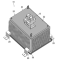
- FIG. 2 is a perspective view showing the hydraulic unit according to the embodiment as viewed from above.
- FIG. 3 is a perspective view showing the hydraulic unit shown in FIG. 1 with the upper plate omitted.
- FIG. 4 is a perspective view showing the hydraulic unit according to the embodiment as viewed from below.
- FIG. 5 is a perspective view showing the main part of the oil tank as viewed from above.
- FIG. 6 is a cross-sectional view showing the main part of the oil tank.
- FIG. 7 is a perspective view showing an air flow in the passage forming cover.
- FIG. 8 is a perspective view showing the hydraulic unit according to Modification 1 of the embodiment with the upper plate omitted.
- FIG. 1 is a hydraulic circuit diagram showing a configuration of a hydraulic unit according to the embodiment.
- FIG. 2 is a perspective view showing the hydraulic unit according to the embodiment as viewed from above.
- FIG. 3 is a perspective view
- FIG. 9 is a perspective view showing a hydraulic unit according to Modification 2 of the embodiment as viewed from below.
- FIG. 10 is a cross-sectional view illustrating a main part of an oil tank according to Modification 2 of the embodiment.
- FIG. 11 is a cross-sectional view illustrating a main part of an oil tank according to Modification 3 of the embodiment.
- FIG. 12 is a cross-sectional view illustrating a main part of an oil tank according to Modification 4 of the embodiment.
- the hydraulic unit (10) of the present embodiment supplies pressure oil to an actuator such as a hydraulic cylinder to operate the actuator.
- the hydraulic unit (10) includes a hydraulic pump (11), a motor (12), a direction switching valve (13), and an oil tank (20).
- the hydraulic pump (11) constitutes a fluid pressure pump that sucks the hydraulic oil stored in the oil tank (20) and discharges it to the actuator.
- the hydraulic pump (11) is a fixed displacement pump such as a gear pump, a trochoid pump, a vane pump, a piston pump, or the like.
- the motor (12) is a variable speed motor that drives the hydraulic pump (11).
- the motor (12) does not have a self-cooling fan.
- the hydraulic pump (11) and the motor (12) are arranged in the oil tank (20). Details of this will be described later.
- the direction switching valve (13) is a 4-port 3-position spring center type electromagnetic switching valve having a first electromagnetic solenoid (13a) and a second electromagnetic solenoid (13b). Of the four ports, the direction switching valve (13) has a P port connected to the discharge side of the hydraulic pump (11) and a T port connected to the oil tank (20). The A port and B port of the direction switching valve (13) are ports connected to the actuator. Note that the type of the direction switching valve (13) described above in this embodiment is merely an example.
- the oil tank (20) includes a rectangular parallelepiped tank body (21), a fan (30), and a passage forming cover (35).
- the shape of the oil tank (20) here is merely an example, and may be a rectangular body such as a cube or a flat rectangular parallelepiped.
- the upper plate (22) of the tank body (21) is fixed by bolt fastening or the like and can be removed.
- a direction switching valve (13) is attached to the upper surface of the upper plate (22).
- the hydraulic pump (11) and the motor (12) are arrange
- the hydraulic pump (11) and the motor (12) are immersed in the hydraulic oil stored in the tank body (21).
- the motor (12) is placed on the bottom plate (27) of the tank body (21) with the drive shaft (12a) extending in the vertical direction.
- the bottom plate (27) is partially bent inward and recessed in a circular shape in plan view.
- the concave portion is a fan storage portion (27a).
- the fan storage section (27a) stores the fan (30) described above.
- the fan storage portion (27a) is a flat circular base that protrudes inward when viewed from the inside of the tank body (21).
- the motor (12) is placed on the circular platform.
- the drive shaft (12a) of the motor (12) has one upper end connected to the hydraulic pump (11) and the other lower end inserted through the through hole (27b) of the fan storage (27a). Projecting into (27a).
- the fan (30) is connected to the end of the drive shaft (12a) protruding into the fan housing (27a).
- the fan (30) of the present embodiment is a turbo fan, and constitutes a cooling fan that cools the tank main body (21) with blown air and cools the hydraulic oil in the tank main body (21).
- the fan (30) may be a sirocco fan having a relatively high static pressure even at a low speed.
- the fan (30) has an impeller (31) that is connected to the drive shaft (12a) of the motor (12) and is rotationally driven.
- the impeller (31) is configured to suck air in the direction of the rotation axis (that is, the axial direction of the drive shaft (12a) of the motor (12)) and blow out air in the radial direction from the center of the rotation axis. That is, the blowing direction of the fan (30) is a direction along the outer surface of the bottom plate (27), and the blown air of the fan (30) flows along the outer surface of the bottom plate (27).
- the passage forming cover (35) described above is provided below the bottom plate (27) of the tank body (21).
- the passage forming cover (35) is disposed at a predetermined distance from the bottom plate (27) of the tank body (21), and has a rectangular substrate (36) that covers the entire outer surface of the bottom plate (27).
- the outer edge portion (37) corresponding to each side of the substrate (36) is bent upward. That is, the outer edge portion (37) of the substrate (36) is bent in the surface direction of the four side plates (23, 24, 25, 26) continuous to the bottom plate (27) in the tank body (21). That is, the passage forming cover (35) is formed in a shallow container shape.
- the fan (30) is disposed inside the passage forming cover (35) and configured to blow air into a space between the bottom plate (27) and the passage forming cover (35). That is, the passage forming cover (35) covers the outer surface of the bottom plate (27) and forms an air passage for the blown air of the fan (30) between the outer surface. As shown in FIGS. 4 and 6, the passage forming cover (35) has an air suction port (36a) at a position corresponding to the suction port of the fan (30). The air inlet (36a) has a bell mouth shape with high intake efficiency. Although not shown, a filter is provided at the air suction port (36a). By providing the filter, it is possible to prevent the fan (30) from sucking dust and releasing it into the air.
- a plurality of fins (23a, 24a, 25a) are provided on the outer surfaces of the side plate (23), the second side plate (24), and the third side plate (25) positioned in the lateral direction.
- the fourth side plate (26) on the side close to the hydraulic pump (11) and the motor (12) is provided with a control panel (not shown) such as the motor (12), so that no fins are provided.
- the fins (23a, 24a, 25a) are formed in a plate shape extending in the vertical direction, and a plurality of the fins (23a, 24, 25) are arranged in a direction perpendicular to the vertical direction in each side plate (23, 24, 25). That is, each fin (23a, 24a, 25a) is extended along the bending direction of the outer edge part (37) of a channel
- the outer edge portion (37) corresponding to the side plate (23, 24, 25) provided with the fins (23a, 24a, 25a) is the fin (23a 24a, 25a) is bent upward at a position slightly outside the protruding end. That is, the outer edge portion (37) corresponding to these three side plates (23, 24, 25) is formed from the fan (30) to the bottom plate (27) of the tank body (21) and the substrate (36) of the passage forming cover (35).
- the guide member is configured to guide the air blown upward between the two to the fins (23a, 24a, 25a).
- the outer edge portion (37) corresponding to the fourth side plate (26) not provided with the fin is bent so as to be in contact with the outer surface of the fourth side plate (26). In this way, the blowout air of the fan (30) is prevented from flowing out to the fourth side plate (26) side by bringing the fourth side plate (26) and the outer edge portion (37) into contact with each other. Thereby, sufficient air can be flowed to the three side plates (23, 24, 25) provided with the fins (23a, 24a, 25a).
- ribs (27c) are provided on the outer surface of the bottom plate (27) of the tank body (21).
- Each rib (27c) is a plate member that is arranged radially in the circumferential direction of the impeller (31) of the fan (30) and extends in the radial direction of the impeller (31).
- Each rib (27c) extends from the vicinity of the outlet of the fan (30) toward the three side plates (23, 24, 25) provided with the fins (23a, 24a, 25a). It is a guide member which guides the blowing air of the fan (30) to the side plate (23, 24, 25) side.
- the rib (27c) also serves as a reinforcing member for reinforcing the bottom plate (27).
- Each rib (27c) does not extend to the fourth side plate (26) side.
- the outer surface of the bottom plate (27) constitutes the first outer wall surface according to the present invention
- three first to third side plates (fins (23a, 24a, 25a)) are provided ( 23, 24, 25) constitute the second outer wall surface according to the present invention.
- the motor (12) generates heat, but since the motor (12) is immersed in the hydraulic oil in the tank body (21), it is cooled by the hydraulic oil. On the other hand, the operating oil is heated by the heat generated by the motor (12). Further, since the hydraulic oil returning from the actuator to the tank main body (21) has a relatively high temperature, the hydraulic oil also increases in temperature.
- the tank body (21) (oil tank (20)) is cooled by the air blown from the fan (30).
- the fan (30) is also driven.
- air suction port (36a) As shown by the arrows in FIG. 7, when the fan (30) is driven, air flows from the air suction port (36a), and the bottom plate (27) of the tank body (21) and the substrate of the passage forming cover (35) ( 36) It flows between.
- the bottom plate (27) of the tank body (21) is cooled.
- the fan (30) blows air in the radial direction, the blown air surely circulates along the outer surface of the bottom plate (27).
- the passage forming cover (35) covers the outer surface of the bottom plate (27) to form an air passage, the blown air of the fan (30) is surely kept away from the outer surface of the bottom plate (27). ) To distribute. By these actions, the bottom plate (27) is sufficiently cooled. The air blown out of the fan (30) and cooled the bottom plate (27) flows to the first to third side plates (23, 24, 25) side, and is moved upward by the outer edge portion (37) of the passage forming cover (35). It flows toward. The air that flows upward flows along the outer surfaces of the first to third side plates (23, 24, 25). Thereby, the first to third side plates (23, 24, 25) are cooled.
- the first to third side plates (23, 24, 25a) are circulated. 24,25) is more cooled. That is, since the fins (23a, 24a, 25a) increase the heat radiation area (that is, the contact area with air), the cooling effect increases. Further, the air blown out from the fan (30) surely flows toward the first to third side plates (23, 24, 25) by the rib (27c) provided on the bottom plate (27). Therefore, a sufficient amount of air flows through the outer surfaces of the first to third side plates (23, 24, 25) and the fins (23a, 24a, 25a).
- the motor (12) is immersed in the hydraulic oil in the oil tank (20), and the drive shaft (12a) of the motor (12) is penetrated from the bottom plate (27).
- a fan (30) is connected to the end. Therefore, the motor (12) can be cooled by the hydraulic oil, and the bottom plate (27) of the tank body (21) and the hydraulic oil can be cooled by the air blown from the fan (30).
- the fan (30) that blows air in the radial direction from the center of the rotating shaft (drive shaft (12a)) is used, the air blown from the fan (30) is reliably supplied to the tank body (21 ) Along the outer surface of the bottom plate (27). Thereby, the bottom plate (27) of the tank body (21) and the hydraulic oil can be sufficiently cooled.
- the passage forming cover (35) that covers the outer surface of the bottom plate (27) and forms the air passage for the blown air of the fan (30) is provided, the blown air of the fan (30) is moved away from the bottom plate (27). And can be reliably distributed along the outer surface of the bottom plate (27). Thereby, the cooling effect of the bottom plate (27) of the tank body (21) and the hydraulic oil can be improved.
- the fan (30) can be circulated along the outer surface of the first to third side plates (23, 24, 25). Therefore, not only the bottom plate (27) but also the first to third side plates (23, 24, 25) can be cooled. Thereby, the cooling effect of the hydraulic oil is further improved.
- the fins (23a, 24a, 25a) are provided on the outer surfaces of the first to third side plates (23, 24, 25) so that air flows through the fins (23a, 24a, 25a), the first to third side plates (23, 24a, 25a)
- the heat radiation area of the third side plate (23, 24, 25) can be increased, and the cooling effect of the first to third side plates (23, 24, 25) is improved.
- the fan (30) is provided on the bottom plate (27) side of the tank body (21). Therefore, even if the air in the passage forming cover (35) flows outside without flowing through the fins (23a, 24a, 25a), it will be blown out to the worker's feet, and the draft received by the worker It can be said that there is almost no feeling. Further, since the air blown out from the fan (30) into the passage forming cover (35) finally flows upward along the outer surfaces of the first to third side plates (23, 24, 25), the hydraulic unit (10) The surrounding workers are hardly affected by the draft.
- the passage formation cover (35) of the present embodiment is formed in a container shape, even if the hydraulic oil leaks from the tank body (21), the leaked hydraulic oil is formed as a passage. Can be stored in the cover (35). That is, in this embodiment, the passage forming cover (35) can also function as a so-called oil pan.
- the first to third side plates (23, 24, 25) are provided with plate-like fins (23a, 24a, 25a), but this modified example is shown in FIG.
- a plurality of air passage portions (23b, 24b, 25b) formed in a cylindrical shape are provided.
- the air passage portions (23b, 24b, 25b) are formed in a cylindrical shape extending along the vertical direction (that is, the bending direction of the outer edge portion (37) of the passage forming cover (35)).
- a plurality of air passage portions (23b, 24b, 25b) are arranged in a direction perpendicular to the vertical direction on the outer surface of the first to third side plates (23, 24, 25).
- the air passage portions (23b, 24b, 25b) extend in the vertical direction of the first to third side plates (23, 24, 25).
- the air passage portion (23b, 24b, 25b) is formed in a cylindrical shape, so that the air is surely prevented from moving away from the first to third side plates (23, 24, 25) in the middle. Circulates along the outer surface of the third side plate (23, 24, 25). Therefore, the cooling effect of the first to third side plates (23, 24, 25) can be enhanced.
- the air passage portions (23b, 24b, 25b) are formed in a cylindrical shape, the heat radiation area (that is, the contact area of air) is increased, and thus the first to third side plates (23, 23, 23) are also increased. 24, 25) can be improved.
- Other configurations, operations, and effects are the same as those of the first embodiment.
- the hydraulic unit (10) of the present modified example omits the passage forming cover (35) in the above-described embodiment, and includes the shielding member (41, 42, 43) and air suction. A member (45) is provided.
- the hydraulic unit (10) of the present modified example includes the first side plate (23), the second side plate (24), and the third side plate (25) among the four side plates (23, 24, 25, 26).
- a shielding member (41, 42, 43) is provided corresponding to each.
- Each shielding member (41, 42, 43) is a plate-like member that is located outside each side plate (23, 24, 25) and extends in the vertical direction.
- Each shielding member (41, 42, 43) is provided so as to protrude downward (to the floor surface) from the bottom plate (27). The protrusion of the shielding member (41, 42, 43) creates a gap between the bottom plate (27) and the floor surface.
- each shielding member (41, 42, 43) extends to the upper end of each side plate (23, 24, 25).
- a plurality of plate-like fins (23c, 24c, 25c) extending in the vertical direction are provided on the outer surface of each side plate (23, 24, 25).
- the fins (23c, 24c, 25c) extend from the upper ends of the side plates (23, 24, 25) to the floor surface, like the shielding members (41, 42, 43). That is, the fins (23c, 24c, 25c) also protrude downward from the bottom plate (27).
- the air suction member (45) is provided on the outer surface of the bottom plate (27).
- the air suction member (45) has a fan communication part (45) and a suction part (47).
- the fan communication part (45) is a cover member that is formed in a flat container shape having a circular shape in plan view and covers the suction part of the fan (30).
- the suction part (47) is a flat cylindrical member having a substantially trapezoidal shape in plan view.
- the suction part (47) communicates with the interior of the fan communication part (45) by connecting the opening end on the side having a smaller opening area to the fan communication part (45).
- the suction portion (47) extends from the fan communication portion (45) toward the fourth side plate (26) on the outer surface of the bottom plate (27). Specifically, the opening end of the suction portion (47) having the larger opening area is flush with the end side of the bottom plate (27) on the fourth side plate (26) side.
- the gap between the bottom plate (27) and the floor serves as an air passage for the blown air, and the blown air reliably flows along the outer surface of the bottom plate (27).
- the blown air flows along the rib (27c) toward the first side plate (23), the second side plate (24), and the third side plate (25).
- the blown air flows in the upward direction by the respective shielding members (41, 42, 43), and flows upward through the fins (23c, 24c, 25c) of the side plates (23, 24, 25). .
- each side plate does not flow out from the gap in the surface direction of the bottom plate (27).
- the hydraulic unit (10) of the present modified example has a convex bell mouth shape in the air suction port (36 a) in the passage forming cover (35) according to the above-described embodiment. . Even in this case, air is sucked in as shown by an arrow in FIG. 11, and the intake efficiency at the air suction port (36a) is increased.
- the rib (27c) is omitted, and the same applies to FIG.
- the hydraulic unit (10) of the present modification is configured such that a shroud (31a) is provided on the impeller (31) of the fan (30) in the above-described embodiment.
- the shroud (31a) is provided at the upstream end (lower end in FIG. 12) of the impeller (31) so as to correspond to the air suction port (36a) of the passage forming cover (35).
- the intake efficiency of the fan (30) is increased. Therefore, in this modification, in combination with the effect of the bell mouth shape of the air suction port (36a) described above, the intake efficiency can be further increased. Therefore, it is possible to further improve the cooling effect on the bottom plate (27) of the tank body (21) and the hydraulic oil.
- the air suction port (36a) does not necessarily have the bell mouth shape described above.
- the present invention may be configured as follows for the above-described embodiment.
- air is circulated along the outer surfaces of the three side plates (23, 24, 25).
- the present invention can be applied to one, two, or four side plates (23, 24, 25).
- 25, 26) may be configured to circulate air along the outer surface.
- the outer edge portion (37) of the passage forming cover (35) is omitted, that is, the passage forming cover (35) is composed of only a flat substrate (36), and air is circulated only on the outer surface of the bottom plate (27). Of course, you may do it.
- the fins (23a, 24a, 25a) are provided only on the outer surfaces of the side plates (23, 24, 25). Fins may be provided not only on the outer surface but also on the inner surface. By doing so, the cooling efficiency for the hydraulic oil can be improved.
- the fins (23a, 24a, 25a) of the side plates (23, 24, 25) and the ribs (27c) of the bottom plate (27) may be omitted.
- the fan (30) is provided on the bottom plate (27) side of the tank body (21).
- the present invention is not limited to this, and other side plates (23, 24, 25,
- the drive shaft (12a) of the motor (12) may be passed through the 26) side, and a fan may be provided at the end.
- it is comprised so that air may distribute
- the fan (30) that blows air radially from the center of the rotating shaft (driving shaft (12a)) is used.
- the present invention is not limited to this.
- the rotating shaft (driving shaft (12a)) A fan that sucks air in the axial direction and blows it out may be used.
- the fan (30) is provided so that the air outlet faces the space between the bottom plate (27) and the passage forming cover (35), and the air is supplied to the air.
- the present invention is useful for a hydraulic unit in which a motor for driving a hydraulic pump is immersed in hydraulic oil in an oil tank.
- Hydraulic unit 11 Hydraulic pump 12 Motor 12a Drive shaft 20 Oil tank 23 First side plate (side plate) 24 Second side plate (side plate) 25 Third side plate (side plate) 23a, 24a, 25a Fin 23b, 24b, 25b Air passage 23c, 24c, 25c Fin 27 Bottom plate 27c rib 30 fans 31 Impeller 31a shroud 35 Passage forming cover 36a Air inlet 37 Outer edge 41,42,43 Shielding member
Landscapes
- Engineering & Computer Science (AREA)
- Mechanical Engineering (AREA)
- General Engineering & Computer Science (AREA)
- Physics & Mathematics (AREA)
- Fluid Mechanics (AREA)
- Chemical & Material Sciences (AREA)
- Analytical Chemistry (AREA)
- Thermal Sciences (AREA)
- Supply Devices, Intensifiers, Converters, And Telemotors (AREA)
Abstract
Un arbre d'entraînement (12a) d'un moteur (12) disposé dans un réservoir d'huile (20) traverse jusqu'à l'extérieur par une plaque de fond (27), et un ventilateur (30) est relié à l'extrémité de l'arbre d'entraînement. Un couvercle formant passage (35) qui recouvre la surface extérieure de la plaque de fond (27), et qui forme un passage d'air pour l'air soufflé hors du ventilateur (30) entre la surface extérieure et le couvercle, est prévu. Le bord extérieur (37) du couvercle formant passage (35) est plié dans la direction de surface de première à troisième plaques latérales (23, 24, 25) qui sont contiguës à la plaque de fond (27).
Applications Claiming Priority (2)
| Application Number | Priority Date | Filing Date | Title |
|---|---|---|---|
| JP2010222584 | 2010-09-30 | ||
| JP2010-222584 | 2010-09-30 |
Publications (1)
| Publication Number | Publication Date |
|---|---|
| WO2012042845A1 true WO2012042845A1 (fr) | 2012-04-05 |
Family
ID=45892335
Family Applications (1)
| Application Number | Title | Priority Date | Filing Date |
|---|---|---|---|
| PCT/JP2011/005424 Ceased WO2012042845A1 (fr) | 2010-09-30 | 2011-09-27 | Unité hydraulique |
Country Status (3)
| Country | Link |
|---|---|
| JP (1) | JP5056975B2 (fr) |
| TW (1) | TW201224294A (fr) |
| WO (1) | WO2012042845A1 (fr) |
Cited By (1)
| Publication number | Priority date | Publication date | Assignee | Title |
|---|---|---|---|---|
| CN105736412A (zh) * | 2016-05-04 | 2016-07-06 | 福州麦辽自动化设备有限公司 | 一种基于液压驱动的多螺旋桨的风扇 |
Families Citing this family (1)
| Publication number | Priority date | Publication date | Assignee | Title |
|---|---|---|---|---|
| KR101901171B1 (ko) * | 2016-12-02 | 2018-11-08 | 김형의 | 유압파워유니트의 소음저감 시스템 |
Citations (6)
| Publication number | Priority date | Publication date | Assignee | Title |
|---|---|---|---|---|
| JPS50103087U (fr) * | 1974-01-30 | 1975-08-25 | ||
| JPH0258107U (fr) * | 1988-10-20 | 1990-04-26 | ||
| JPH02110701U (fr) * | 1989-02-21 | 1990-09-05 | ||
| JPH07127097A (ja) * | 1993-11-04 | 1995-05-16 | Hitachi Constr Mach Co Ltd | 建設機械 |
| JP2006258271A (ja) * | 2005-03-18 | 2006-09-28 | Toyooki Kogyo Co Ltd | 油圧装置 |
| JP2008138536A (ja) * | 2006-11-30 | 2008-06-19 | Matsushita Electric Ind Co Ltd | 遠心送風機 |
-
2011
- 2011-09-27 WO PCT/JP2011/005424 patent/WO2012042845A1/fr not_active Ceased
- 2011-09-27 JP JP2011210430A patent/JP5056975B2/ja not_active Expired - Fee Related
- 2011-09-30 TW TW100135678A patent/TW201224294A/zh unknown
Patent Citations (6)
| Publication number | Priority date | Publication date | Assignee | Title |
|---|---|---|---|---|
| JPS50103087U (fr) * | 1974-01-30 | 1975-08-25 | ||
| JPH0258107U (fr) * | 1988-10-20 | 1990-04-26 | ||
| JPH02110701U (fr) * | 1989-02-21 | 1990-09-05 | ||
| JPH07127097A (ja) * | 1993-11-04 | 1995-05-16 | Hitachi Constr Mach Co Ltd | 建設機械 |
| JP2006258271A (ja) * | 2005-03-18 | 2006-09-28 | Toyooki Kogyo Co Ltd | 油圧装置 |
| JP2008138536A (ja) * | 2006-11-30 | 2008-06-19 | Matsushita Electric Ind Co Ltd | 遠心送風機 |
Cited By (1)
| Publication number | Priority date | Publication date | Assignee | Title |
|---|---|---|---|---|
| CN105736412A (zh) * | 2016-05-04 | 2016-07-06 | 福州麦辽自动化设备有限公司 | 一种基于液压驱动的多螺旋桨的风扇 |
Also Published As
| Publication number | Publication date |
|---|---|
| JP5056975B2 (ja) | 2012-10-24 |
| TW201224294A (en) | 2012-06-16 |
| JP2012092972A (ja) | 2012-05-17 |
Similar Documents
| Publication | Publication Date | Title |
|---|---|---|
| US10156059B2 (en) | Construction machine including engine | |
| WO2013161617A1 (fr) | Boîtier refroidi par air | |
| JP5802967B2 (ja) | パッケージ型の回転ポンプ装置ユニット | |
| EP3103929A1 (fr) | Machine de construction avec moteur | |
| JP2016097802A (ja) | エンジンルーム通風構造 | |
| JP5850024B2 (ja) | 作業機械 | |
| JP2014088757A (ja) | 機械部品を有する建設機械 | |
| JP2007283801A (ja) | 建設機械 | |
| JP6496634B2 (ja) | 建設機械の排風構造 | |
| JP5056975B2 (ja) | 油圧ユニット | |
| CN107709788B (zh) | 封装型空冷式螺旋压缩机 | |
| JP5252052B2 (ja) | 油圧ユニット | |
| CN111121359B (zh) | 冷却系统 | |
| KR20120085618A (ko) | 건설중장비의 엔진룸 냉각장치 | |
| KR101705781B1 (ko) | 터보블로워의 외함 | |
| KR20150071830A (ko) | 팬 쉬라우드 | |
| JP7025247B2 (ja) | 冷却器付き電動機 | |
| JP4735214B2 (ja) | 空気調和機用室外機 | |
| JP7584293B2 (ja) | トランスアクスル | |
| JP4520892B2 (ja) | 作業機械の冷却構造 | |
| JP6660173B2 (ja) | 作業機械 | |
| JP7029320B2 (ja) | 冷却器付き電動機 | |
| JP6733078B2 (ja) | 冷蔵庫 | |
| JP7243232B2 (ja) | 冷却装置 | |
| JP4631038B2 (ja) | パッケージ型コンプレッサ |
Legal Events
| Date | Code | Title | Description |
|---|---|---|---|
| 121 | Ep: the epo has been informed by wipo that ep was designated in this application |
Ref document number: 11828411 Country of ref document: EP Kind code of ref document: A1 |
|
| NENP | Non-entry into the national phase |
Ref country code: DE |
|
| 122 | Ep: pct application non-entry in european phase |
Ref document number: 11828411 Country of ref document: EP Kind code of ref document: A1 |