WO2012042886A1 - Dispositif de détection de biomolécules et procédé de détection de biomolécules - Google Patents
Dispositif de détection de biomolécules et procédé de détection de biomolécules Download PDFInfo
- Publication number
- WO2012042886A1 WO2012042886A1 PCT/JP2011/005498 JP2011005498W WO2012042886A1 WO 2012042886 A1 WO2012042886 A1 WO 2012042886A1 JP 2011005498 W JP2011005498 W JP 2011005498W WO 2012042886 A1 WO2012042886 A1 WO 2012042886A1
- Authority
- WO
- WIPO (PCT)
- Prior art keywords
- light
- external force
- complex
- molecules
- biomolecule detection
- Prior art date
- Legal status (The legal status is an assumption and is not a legal conclusion. Google has not performed a legal analysis and makes no representation as to the accuracy of the status listed.)
- Ceased
Links
Images








Classifications
-
- G—PHYSICS
- G01—MEASURING; TESTING
- G01N—INVESTIGATING OR ANALYSING MATERIALS BY DETERMINING THEIR CHEMICAL OR PHYSICAL PROPERTIES
- G01N21/00—Investigating or analysing materials by the use of optical means, i.e. using sub-millimetre waves, infrared, visible or ultraviolet light
- G01N21/62—Systems in which the material investigated is excited whereby it emits light or causes a change in wavelength of the incident light
- G01N21/63—Systems in which the material investigated is excited whereby it emits light or causes a change in wavelength of the incident light optically excited
- G01N21/64—Fluorescence; Phosphorescence
- G01N21/6486—Measuring fluorescence of biological material, e.g. DNA, RNA, cells
-
- G—PHYSICS
- G01—MEASURING; TESTING
- G01N—INVESTIGATING OR ANALYSING MATERIALS BY DETERMINING THEIR CHEMICAL OR PHYSICAL PROPERTIES
- G01N21/00—Investigating or analysing materials by the use of optical means, i.e. using sub-millimetre waves, infrared, visible or ultraviolet light
- G01N21/62—Systems in which the material investigated is excited whereby it emits light or causes a change in wavelength of the incident light
- G01N21/63—Systems in which the material investigated is excited whereby it emits light or causes a change in wavelength of the incident light optically excited
- G01N21/64—Fluorescence; Phosphorescence
- G01N21/6428—Measuring fluorescence of fluorescent products of reactions or of fluorochrome labelled reactive substances, e.g. measuring quenching effects, using measuring "optrodes"
Definitions
- the present invention relates to a technique for detecting a detection target substance in a solution, and more particularly, to a biomolecule detection apparatus and a biomolecule detection method capable of detecting biomolecules, viruses, nucleic acids, proteins, bacteria, and the like in a specimen.
- the biomolecule detection method is a method that selectively detects only a substance to be detected from a bodily fluid having a plurality of components such as blood, urine, and sweat by high selectivity using a specific reaction such as an antigen-antibody reaction. is there.
- a biomolecule detection method is widely used for detection, inspection, quantification, and analysis of biomolecules such as viruses, nucleic acids, proteins, and bacteria.
- Radioimmunoassay has been put to practical use as a biomolecule detection method.
- an antigen or antibody labeled with an isotope is used to detect the presence or absence of an antibody or antigen that specifically binds to the antigen or antibody.
- the radioimmunoassay quantifies a detection target substance such as an antibody or an antigen by measuring the radiation dose of an isotope, and can perform highly sensitive measurement.
- Fluorescence immunoassay is a biomolecule detection method that does not use radioactive substances.
- an antibody is immobilized on a reaction layer in advance (this is referred to as a solid phase), and a solution to be measured and an antibody labeled with a fluorescent molecule are passed through the reaction layer, and fluorescence near the reaction layer is measured.
- a solution to be measured and an antibody labeled with a fluorescent molecule are passed through the reaction layer, and fluorescence near the reaction layer is measured.
- an apparatus for measuring the concentration of an antigen specifically bound to an antibody is known (for example, see Patent Document 1).
- the fluorescence immunoassay using a solid phase has a problem that it takes a high cost to prepare the solid phase.
- a method for detecting a biomolecule in a liquid without using a solid phase that is, using only the liquid phase
- the fluorescence polarization method is a method for detecting a change in the value of the degree of fluorescence polarization based on a change in Brownian motion, which occurs when another molecule binds to a fluorescently labeled molecule and the size of the molecule changes.
- a biomolecule detection method using a fluorescence polarization method is known as a simple and quick detection method for a substance to be detected in a specimen (see, for example, Patent Document 2).
- Patent Document 2 describes that a third molecule is used in order to sufficiently change the volume of the particle. In this case, it is necessary to prepare the third molecule in advance.
- the present invention has been made in view of the above circumstances, and an object thereof is to provide a biomolecule detection apparatus and a biomolecule detection method capable of highly sensitive measurement with a simple configuration.
- a biomolecule detection apparatus comprises: A first complex in which a substance that specifically binds to the detection target substance and a fluorescent molecule are bound to each other, and a second complex in which the first complex and the detection target substance are bound to each other in the solution; A biomolecule detection apparatus for detecting or quantifying a detection target substance by detecting fluorescence generated from a first complex and a second complex, A light source that emits excitation light toward fluorescent molecules; A light receiving unit for receiving fluorescence generated from fluorescent molecules; An external force applying means for applying an external force to the first composite and the second composite; Computation means for detecting or quantifying the detection target substance based on the Brownian motion speed of the first complex and the Brownian motion speed of the second complex, which are changed by applying external force.
- the light source emits linearly polarized excitation light that excites the fluorescent molecules
- the light receiving unit converts the fluorescence generated from the fluorescent molecules into the vibration direction of the excitation light.
- It has a separating means for separating the first component having a parallel vibration direction and a second component having a vibration direction perpendicular to the vibration direction of the excitation light. It is preferable to detect or quantify the detection target substance using both the first component and the second component. In this case, it is preferable that the calculation means obtains the degree of fluorescence polarization from the first component and the second component to detect or quantify the second complex.
- the separating means is preferably a polarizing beam splitter.
- the light source emits excitation light so as to focus on a specific region in the solution
- the light receiving unit receives fluorescence generated from the fluorescent molecules in the specific region.
- the computing means is based on a parameter representing the frequency with which the first complex enters and exits the specific area and a parameter representing the frequency with which the second complex enters and exits the specific area. It is preferable to perform detection or quantification.
- the computing means includes an autocorrelator, and determines the Brownian motion speeds of the first complex and the second complex by the autocorrelation method, using the above parameters as the speed of the Brownian motion. It is preferable that the detection target substance is detected or quantified by obtaining the average size of the molecules contained in.
- the light receiving unit includes a spectroscopic unit that splits light and a plurality of light receiving units that respectively receive the light dispersed by the spectroscopic unit.
- the spectroscopic unit is a plurality of optical filters having different wavelengths of light to be transmitted, and the light receiving unit further includes a switching unit that switches an optical filter to be used from the plurality of optical filters, according to the wavelength of the fluorescence. It is preferable to switch the optical filter to be used.
- the spectroscopic means is preferably a diffraction grating.
- the external force applying means includes an external force applying light source that irradiates light having a wavelength different from that of the excitation light, and the external force is applied to the first complex and the second complex by irradiating the solution with light having a wavelength different from that of the excitation light. It is preferable to add.
- the external force imparting light source is preferably one that irradiates the solution with the light having a wavelength different from that of the excitation light from a plurality of positions.
- the external force applying means is an external force applying light source that emits light having a wavelength different from that of the excitation light
- the external force applying light source irradiates the light having a wavelength different from that of the excitation light in the direction of exiting the plane through the solution, and the excitation light and the wavelength are at the interface between the solution and the plane. It is preferable to focus on the different light.
- the computing means uses the fact that external forces having different strengths are applied to the first complex and the second complex by the external force applying means, respectively. It is preferable to detect or quantify the complex.
- the biomolecule detection method includes: A first complex in which a substance that specifically binds to the detection target substance and a fluorescent molecule are bound to each other, and a second complex in which the first complex and the detection target substance are bound to each other in the solution; A biomolecule detection method for detecting or quantifying a detection target substance by detecting fluorescence generated from a first complex and a second complex, Irradiating excitation light to excite fluorescent molecules; Applying an external force to the first complex and the second complex; Detecting fluorescence generated from fluorescent molecules by irradiation of excitation light; Detecting or quantifying the detection target substance based on the Brownian motion speed of the first complex and the Brownian motion speed of the second complex, which are changed by applying external force.
- biomolecule detection can be performed.
- FIG. 3 is a schematic diagram for explaining an outline of an antigen-antibody reaction of the biomolecule detection apparatus according to the first embodiment.
- FIG. 3 is a schematic diagram for explaining an outline of an antigen-antibody reaction of the biomolecule detection apparatus according to the first embodiment. It is the model showing the case where the vibration direction of excitation light and the transition moment of a fluorescent molecule are mutually parallel. It is a schematic diagram showing the case where the vibration direction of excitation light and the transition moment of fluorescent molecules are perpendicular to each other. It is the schematic diagram showing the free molecule
- FIG. 1 is an external perspective view of a biomolecule detection apparatus according to Embodiment 1.
- FIG. It is an external appearance perspective view at the time of opening the opening-closing part of the biomolecule detection apparatus which concerns on Embodiment 1.
- FIG. It is a block diagram which shows the main structures of a biomolecule detection apparatus. It is the schematic diagram which looked at the irradiation direction of the external force provision light irradiated from an external force provision light source part from the upper surface. It is a graph showing the relationship between the speed of Brownian motion and the number of molecules when no external force imparting light is irradiated. It is a graph showing the relationship between the speed of Brownian motion and the number of molecules when irradiated with external force imparting light.
- FIG. 4 is a schematic diagram illustrating a detailed configuration of a light receiving unit in the biomolecule detection apparatus according to Embodiment 1.
- FIG. It is an example of a calibration curve showing the relationship between the concentration of the detection target substance and the degree of fluorescence polarization. It is the figure which represented typically the flow from sample preparation to disposal.
- FIG. 6 is a block diagram illustrating a main configuration of a biomolecule detection apparatus according to Embodiment 2. 6 is a schematic diagram illustrating a detailed configuration of a light receiving unit in a biomolecule detection apparatus according to Embodiment 2.
- FIG. It is an example of the graph showing the relationship between a diffusion time and a correlation function. It is an example of a calibration curve representing the relationship between antigen concentration and average diffusion time.
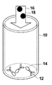
- FIGS. 1A and 1B are schematic diagrams showing an outline of an antigen-antibody reaction in the biomolecule detection apparatus according to Embodiment 1 of the present invention.
- the antigen-antibody reaction in the liquid will be described with reference to FIGS. 1A and 1B.
- a dried antibody 12 is placed in a cylindrical reagent cup 10.
- the antibody 12 is labeled with a fluorescent molecule 14.
- the specimen is plasma 16 separated from whole blood.
- the plasma 16 is dispensed into the reagent cup 10 and stirred, if an antigen 18 that specifically binds to the antibody 12 is present in the plasma 16, an antigen-antibody reaction occurs between the antibody 12 and the antigen 18. As shown in FIG. 1B, antigen 12 and antibody 18 are specifically bound and present in plasma 16.
- binding molecule the complex of the antibody 12 and the antigen 18 and the fluorescent molecule 14 bound by the antigen-antibody reaction
- the complex of the antibody 12 and the fluorescent molecule 14 floating in the liquid without the antigen-antibody reaction is called a free molecule.
- Binding molecules and free molecules are mixed in the plasma solution.
- components other than the antigen 18 exist in the plasma 16, components other than the antigen 18 are omitted in FIGS. 1A and 1B for the sake of simplicity.
- the biomolecule detection apparatus irradiates excitation light to a solution in which free molecules and binding molecules are mixed due to the liquid phase, and receives fluorescence generated from the fluorescent molecules 14.
- the antigen 18 is detected and quantified. Therefore, it is desirable to detect only the fluorescence generated from the binding molecule containing the antigen 18.
- fluorescence is also generated from the fluorescent molecules 14 associated with the free molecules. This fluorescence becomes an unnecessary component in relation to the fluorescence generated from the fluorescent molecule 14 accompanying the binding molecule. Therefore, the biomolecule detection apparatus according to Embodiment 1 of the present invention calculates the contribution of fluorescence generated from the fluorescent molecules 14 associated with the binding molecules from the total fluorescence data.
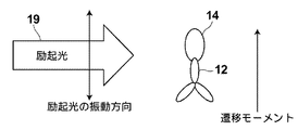
- FIG. 2A is a schematic diagram showing a case where the vibration direction of the excitation light 19 and the transition moment of the fluorescent molecule 14 are parallel to each other
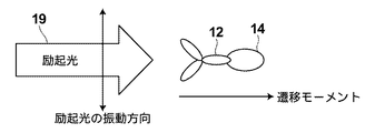
- FIG. 2B is a diagram where the vibration direction of the excitation light 19 and the transition moment of the fluorescent molecule 14 are perpendicular to each other.
- It is a schematic diagram showing a case.
- the orientation of the fluorescent molecules 14 (the major axis direction of the fluorescent molecules 14 indicated by ellipses) and the direction of the transition moment are drawn in a uniform manner.
- the “vibration direction” of light means the vibration direction of an electric field, and has the same meaning as the polarization direction when light is polarized.
- Fluorescent molecules 14 transition to an excited state when absorbing light energy, and emit fluorescence in the process of returning to the ground state.
- a vector in the fluorescent molecule 14 called a transition moment determined by the molecular structure of the fluorescent molecule 14 interacts with the excitation light 19.
- the transition moment has a specific direction in the fluorescent molecule 14, and the relationship between the direction of the transition moment and the vibration direction of the excitation light 19 determines the excitation efficiency of the fluorescent molecule 14.
- the fluorescent molecule 14 selectively absorbs light that vibrates in a direction parallel to the transition moment. Therefore, as shown in FIGS.
- the vibration direction of the linearly polarized excitation light 19 is the fluorescent molecule.
- the excitation efficiency is highest when parallel to the direction of the transition moment of FIG. 14 (FIG. 2A), and the excitation increases as the angle between the vibration direction of the linearly polarized excitation light 19 and the direction of the transition moment of the fluorescent molecule 14 increases. The efficiency decreases, and the excitation efficiency becomes zero when the vibration direction of the linearly polarized excitation light 19 is orthogonal to the transition moment of the fluorescent molecule 14 (FIG. 2B). Since the direction of the transition moment varies depending on the direction of the fluorescent molecule 14, the direction of the fluorescent molecule 14 in the solution affects the excitation efficiency of the fluorescent molecule 14.
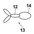
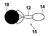
- FIG. 3A is a schematic diagram showing the antibody 12 and the fluorescent molecule 14 constituting the free molecule 13.
- FIG. 3B is a schematic diagram showing the antibody 12, the antigen 18, and the fluorescent molecule 14 constituting the binding molecule.
- the free molecules 13 and the binding molecules 15 move irregularly (Brownian motion) in the solution, and move and rotate in the solution. It is known that the Brownian motion of molecules in a solution is affected by absolute temperature, molecular volume, molecular mass, solvent viscosity, and the like.
- the binding molecule 15 has a volume larger than that of the free molecule 13 by the amount of the antigen 18, and does not easily perform Brownian motion in the solution.
- a method of detecting a detection target substance by detecting a change in Brownian motion caused by a change in the size of the molecule due to binding of a fluorescently labeled molecule to the detection target substance (change in the degree of polarization of fluorescence) ( Fluorescence polarization method) is known.
- the degree of polarization is a scale representing the polarization state of light, and takes a value from 0 to 1, with 1 representing completely polarized light (for example, linearly polarized light) and 0 representing non-polarized light.
- the fluorescent molecule 14 when the fluorescent molecule 14 is excited with linearly polarized excitation light, the fluorescent molecule 14 emits fluorescence polarized in a direction parallel to the vibration direction of the excitation light.
- the degree of polarization of fluorescence emitted by the fluorescent molecules 14 depends on the speed of Brownian movement of the fluorescent molecules 14. If the fluorescent molecule 14 does not perform Brownian motion, the fluorescent molecule 14 emits fluorescence polarized in a direction parallel to the vibration direction of the excitation light, and the faster the Brownian motion of the fluorescent molecule 14 is, the more the fluorescence generated from the fluorescent molecule 14 becomes. The degree of polarization is low.
- the free molecules 13 and the binding molecules 15 have different rotational speeds in the solution due to factors such as mass and volume. Therefore, the polarization degree of the fluorescence generated from the fluorescent molecule 14 associated with the free molecule 13 and the polarization degree of the fluorescence generated from the fluorescent molecule 14 associated with the binding molecule 15 are different from each other, and the fluorescent molecule 14 associated with the binding molecule 15 is different. The degree of polarization of the fluorescence generated from is larger.
- the degree of fluorescence polarization P is defined by the following formula (1), and indicates the degree to which the fluorescent molecule rotates between excitation and fluorescence emission.
- I1 represents fluorescence polarized in a direction parallel to the vibration direction of linearly polarized excitation light
- I2 represents fluorescence polarized in a direction perpendicular to the vibration direction of linearly polarized excitation light.
- P (I1-I2) / (I1 + I2) (1)
- the relationship between the free molecules 13 and the binding molecules 15 and the degree of fluorescence polarization shown in the present embodiment is that there are many binding molecules 15 in the solution that are larger in volume and mass and have a slower Brownian motion than the free molecules 13 by the amount of the antigen 18. That is, there is a relationship that the degree of fluorescence polarization increases as the number of fluorescent molecules that generate fluorescence polarized in a direction parallel to the vibration direction of linearly polarized excitation light increases.
- the fluorescence polarization method has a limit in detection sensitivity because it detects a change in the degree of fluorescence polarization due to a random motion change called Brownian motion.
- Brownian motion a random motion change
- the biomolecule detection apparatus applies an external force to the free molecules 13 and the binding molecules 15 in the solution using a laser, and the speed of the Brownian motion of the free molecules 13 and the binding molecules 15 are increased. A significant difference is made in the speed of Brownian motion, and the degree of fluorescence polarization is measured with high accuracy.
- the free molecules 13 and the binding molecules 15 in the solution When the free molecules 13 and the binding molecules 15 in the solution are irradiated with laser, the free molecules 13 and the binding molecules 15 in the solution receive an external force and inhibit the Brownian motion.
- the external force received by the binding molecule 15 by the laser is Fb and the external force Ff received by the free molecule 13, the free molecule 13 and the binding molecule 15 have different volumes and masses depending on the presence or absence of the antigen 18. The magnitudes of the external forces received are different from each other, and Fb> Ff.
- the biomolecule detection apparatus inhibits the Brownian motion of the free molecules 13 and the binding molecules 15 by applying external forces having different strengths to the free molecules 13 and the binding molecules 15 by the laser. , Causing a significant difference in the degree of fluorescence polarization.
- FIG. 4A is an external perspective view of the biomolecule detection apparatus 100.
- a display unit 102 On the side surface of the biomolecule detection apparatus 100, there are a display unit 102, a user input unit 104, and an opening / closing unit 106.
- the display unit 102 displays measurement results and the like.
- the user input unit 104 is a part where the user sets a mode and inputs sample information.
- the opening / closing unit 106 is configured to be able to open and close the upper lid. The upper lid is opened when the specimen is set, and the upper lid is closed during measurement. With this configuration, external light is prevented from affecting the measurement.
- FIG. 4B is an external perspective view of the biomolecule detection apparatus 100 when the opening / closing part 106 is opened.
- the opening / closing part 106 When the opening / closing part 106 is opened, the reagent cup 108 and the holding table 110 are exposed to the outside.
- the reagent cup 108 is held on the holding table 110 and is detachable from the holding table 110.
- the reagent cup 108 is a cylindrical container for storing a solution.
- the user dispenses the sample into the reagent cup 108 and closes the upper lid to perform measurement.
- a reagent tank and a dispensing unit are provided in the biomolecule detection apparatus 100. When the measurement is started, the dispensing unit sucks up the reagent from the reagent tank and dispenses it into the reagent cup 108. To do.
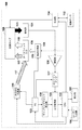
- FIG. 5 is a functional block diagram for explaining the main configuration of the biomolecule detection apparatus 100.
- the biomolecule detection apparatus 100 includes a display unit 102, a user input unit 104, a reagent cup 108, a reagent tank 112, a dispensing unit 114, an external force applying light source unit 116, an excitation light source unit 118, an FG (Function Generator) 122, and a light receiving unit 124. , An amplifier 126, a lock-in amplifier 127, an A / D converter 128, a sampling clock generator 130, a CPU 132, and a dichroic mirror 138.
- the reagent cup 108 is a container for reacting a reagent stored in the reagent tank 112 with a sample collected from a patient or the like.
- the reagent cup 108 is detachable from the biomolecule detection apparatus 100.
- the volume of the reagent cup 108 is about 120 ⁇ L, for example.
- the reagent tank 112 is a tank that stores a plurality of types of reagents.
- the free molecules 13 are stored as reagents in the reagent tank 112.
- the dispensing unit 114 is configured by a detachable pipette or a suction device. In accordance with an instruction from the CPU 132, the dispensing unit 114 sucks up the reagent used for measurement from the reagent tank 112 with a pipette and dispenses it into the reagent cup 108.
- the external force applying light source 116 irradiates the external force applying light 117 toward the dichroic mirror 138 and applies an external force to the free molecules 13 and the binding molecules 15 existing in the solution in the reagent cup 108.
- ON / OFF of the external force applying light source unit 116 is periodically switched by a voltage signal output from the FG 122.
- the external force imparting light 117 for example, a laser having a wavelength of 980 nm and an output of 100 mW is used.
- the external force imparting light 117 has a width that illuminates the entire solution of the reagent cup 108.
- the excitation light source unit 118 excites the fluorescent molecules 14 by irradiating the reagent cup 108 with the excitation light 119 linearly polarized by the polarizer provided therein through the dichroic mirror 138.
- the excitation light for example, light having a wavelength of 532 nm and an output of 1 mW is used.
- the dichroic mirror 138 is a mirror that reflects light of a specific wavelength and transmits light of other wavelengths.
- the dichroic mirror 138 reflects the external force applying light 117 and transmits the excitation light 119.
- the FG 122 is a device capable of generating voltage signals having various frequencies and waveforms.
- the FG 122 receives a command output from the CPU 132, and receives an external force applying light source unit 116, an excitation light source unit 118, a lock-in amplifier 127, and a sampling.
- a voltage signal is output to the clock generator 130.
- the light receiving unit 124 is configured by a filter, a photodiode, or the like.
- the light receiving unit 124 is provided below the reagent cup 108, receives fluorescence 123 generated from the fluorescent molecules 14 in the reagent cup 108 at the lower part of the reagent cup 108, and receives the received light signal as an analog electrical signal (analog fluorescence data). ) And output to the amplifying unit 126.
- the amplifying unit 126 amplifies the analog fluorescence data output from the light receiving unit 124 and outputs the amplified data to the lock-in amplifier 127.
- the lock-in amplifier 127 converts the analog fluorescence data to a direct current.
- the lock-in amplifier 127 receives a square wave as a reference signal from the FG 122. This square wave has the same period as the voltage signal output from the FG 122 to the external force applying light source unit 116.
- the lock-in amplifier 127 detects a frequency component equal to the reference signal from the analog fluorescence data output from the amplification unit 126. Specifically, the lock-in amplifier 127 converts only a frequency component equal to the reference signal into a DC signal by synchronous detection, and passes only the DC signal through a low-pass filter provided therein.
- the lock-in amplifier 127 outputs a DC signal to the A / D conversion unit 128.
- the lock-in amplifier 127 detects, from the analog fluorescence data output from the amplifying unit 126, a component having the same cycle as the cycle in which the external force applying light source unit 116 emits light. By detecting a component having the same period as the period at which the external force imparting light source 116 emits light, the lock-in amplifier 127 reduces the influence of stray light, electric noise, etc. included in the analog fluorescence data.
- the sampling clock generation unit 130 outputs to the A / D conversion unit 128 a sampling clock that specifies the timing at which the A / D conversion unit 128 samples the analog fluorescence data based on the voltage signal output from the FG 122.
- the A / D converter 128 samples the analog fluorescence data output from the lock-in amplifier 127 based on the sampling clock output from the sampling clock generator 130, and converts the sampled analog fluorescence data into digital data. To the CPU 132.
- the CPU 132 calculates the digital data output from the A / D conversion unit 128 and outputs the result to the display unit 102.
- the CPU 132 receives an input from the user input unit 104 and issues an instruction command for operations of the external force applying light source unit 116, the excitation light source unit 118, the dispensing unit 114, and the FG 122.
- the CPU 132 issues an ON / OFF command to the external force applying light source unit 116 and the excitation light source unit 118, and instructs the dispensing unit 114 to specify a reagent to be used and start a dispensing operation.
- An instruction is issued, and an instruction to output a waveform of a voltage signal to be output and an output instruction to the FG 122 are performed.
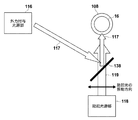
- FIG. 6 is a schematic view of the inside of the biomolecule detection apparatus 100 as viewed from the upper surface side in order to explain the irradiation direction of the external force applying light emitted from the external force applying light source unit 116.
- the external force applying light 117 emitted from the external force applying light source 116 is reflected by the dichroic mirror 138 and applied to the side surface of the reagent cup 108.
- the dichroic mirror 138 reflects light having the wavelength used for the external force imparting light 117 and transmits light having other wavelengths.
- the excitation light 119 emitted from the excitation light source 118 passes through the dichroic mirror 138, travels in the same direction as the external force imparting light 117 reflected by the dichroic mirror 138, and enters the side surface of the reagent cup 108.
- the external force applying light 117 incident on the reagent cup 108 applies an external force to the free molecules 13 and the binding molecules 15 in the reagent cup 108 and inhibits the Brownian motion of each molecule.
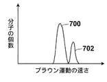
- FIG. 7A is a graph showing the relationship between the speed of Brownian motion and the number of molecules when no external force imparting light is irradiated
- FIG. 7B shows the relationship between the speed of Brownian motion and the number of molecules when irradiated with external force imparting light. It is a represented graph. In FIGS. 7A and 7B, graphs are schematically drawn for easy understanding.
- Curve 700 is a graph showing the relationship between the speed of Brownian motion of binding molecules and the number of molecules.
- a curve 702 is a graph showing the relationship between the speed of Brownian motion of free molecules and the number of molecules.
- the Brownian motion of the binding molecule is slower than the Brownian motion of the free molecule.
- the number of binding molecules is larger than the number of free molecules.
- the Brownian motion of the free molecules 13 and the binding molecules 15 in the reagent cup 108 irradiated with the external force imparting light 117 is inhibited by the external force. Since the external force imparting light 117 exerts a larger force as the volume of the molecule increases, the external force received by the binding molecule 15 is greater than the external force received by the free molecule 13. Therefore, the Brownian motion of the binding molecule 15 is inhibited by a stronger force than the Brownian motion of the free molecule 13, and the Brownian motion of the binding molecule 15 is slower than usual (shown by a curve 704 in FIG. 7B).
- the fluorescence generated from the binding molecule 15 irradiated with the external force imparting light 117 has a high degree of polarization because the speed of the Brownian motion of the binding molecule 15 is slower than when the external force imparting light 117 is not irradiated. It contains many components polarized in a direction parallel to the vibration direction of 119.
- the volume of the free molecule 13 is smaller than the volume of the binding molecule 15, the external force received by the free molecule 13 by the external force applying light 117 is smaller than the external force received by the binding molecule 15. Therefore, the speed of the Brownian motion of the free molecules 13 does not change much depending on the presence / absence of the external force imparting light 117 (shown by a curve 706 in FIG. 7B). Therefore, the change in the degree of polarization of the fluorescence generated from the fluorescent molecules 14 accompanying the free molecules 13 due to the presence or absence of the external force imparting light 117 is small.
- the biomolecule detection apparatus 100 can perform fluorescence polarization degree measurement with high accuracy.
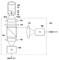
- FIG. 8 is a schematic diagram illustrating a detailed configuration of the light receiving unit 124.
- the light receiving unit 124 includes a lens 142, a filter 144, a polarization beam splitter 146, a lens 147, a lens 148, a PD (photodiode) 149 and a PD 150.
- the light receiving unit 124 receives fluorescence from the bottom side of the reagent cup 108.
- the fluorescence 123a generated from the fluorescent molecules 14 in the reagent cup 108 and incident on the left side portion of the light receiving unit 124 and the fluorescent light 123b incident on the right side portion of the light receiving unit 124 are collected and collimated by the lens 142, and are filtered. It enters the polarization beam splitter 146 through 144.
- fluorescence also exists between the fluorescence 123a and the fluorescence 123b, and the behavior thereof can be predicted by those skilled in the art, and thus the description thereof is omitted.
- the filter 144 is a band-pass filter that cuts light other than fluorescence generated from the fluorescent molecules 14, and prevents light other than fluorescence such as excitation light from entering the PD 149 and the PD 150.
- the polarization beam splitter 146 transmits light that vibrates in a direction parallel to the vibration direction of the excitation light 119 and reflects light that vibrates in a direction perpendicular to the vibration direction of the excitation light 119.
- the fluorescence transmitted through the polarization beam splitter 146 is collected by the lens 148 and enters the PD 149.
- the fluorescence reflected by the polarization beam splitter 146 is collected by the lens 147 and enters the PD 150.
- PD 149 is configured by APD (Avalanche Photodiode), generates a current corresponding to the intensity of the fluorescence collected by lens 148, and outputs the current to amplification unit 126.
- APD Anavalanche Photodiode
- the PD 150 is composed of an APD, generates a current corresponding to the intensity of the fluorescence collected by the lens 147, and outputs the current to the amplifying unit 126.
- the light receiving unit 124 converts the fluorescence generated from the fluorescent molecules 14 into a component having a vibration direction parallel to the vibration direction of the excitation light 119 and a component having a vibration direction perpendicular to the vibration direction of the excitation light 119.
- the current is generated based on the amount of each component.
- the light receiving unit 124 since the light receiving unit 124 receives fluorescence on the bottom surface side of the reagent cup 108, the light receiving unit 124 is not easily affected by the external force applying light 117 and the excitation light 119.
- the CPU 132 obtains the fluorescence polarization degree by performing the same calculation as the calculation for obtaining the fluorescence polarization degree shown in Expression (1) from the current component based on the fluorescence separated by the light receiving unit 124.
- the external force imparting light 117 is irradiated, there is a significant difference between the speed of the Brownian motion of the free molecules 13 and the speed of the Brownian motion of the binding molecules 15, and the ratio of the number of these molecules becomes the fluorescence polarization degree. appear.
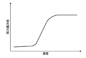
- the CPU 132 stores in advance a calibration curve function that is different for each measurement item, and converts the degree of fluorescence polarization into the concentration of the antigen.
- FIG. 9 shows an example of a calibration curve function.
- the calibration curve function is measured using a sample or the like whose concentration of a specific substance is known in advance.
- the CPU 132 outputs the calculated antigen concentration to the display unit 102.
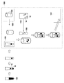
- FIG. 10 is a diagram schematically showing the flow from sample preparation to disposal.
- whole blood 156 collected from a patient is centrifuged at 50 ⁇ L to separate plasma 16.
- the separated plasma 16 is set in the specimen setting unit 152 of the biomolecule detection apparatus 100. The work so far is done by the user.
- the biomolecule detection apparatus 100 dispenses the plasma 16 set in the sample setting unit 152 into an unused reagent cup 108 stocked in the reagent cup stock unit 160. Subsequently, the biomolecule detection apparatus 100 sucks up the anti-PSA antibody in the reagent tank 112 with the pipette 158 and dispenses it into the reagent cup 108.
- the biomolecule detection apparatus 100 in which the plasma and the anti-PSA antibody are placed in the reagent cup 108 causes an antigen-antibody reaction by vibrating the reagent cup 108 with a built-in vortex mixer while controlling the temperature at 37 ° C. Thereafter, the biomolecule detection apparatus 100 performs irradiation with excitation light and fluorescence detection, and discards the reagent cup 108 in the built-in trash box 154 after the fluorescence detection is completed.
- the external force is applied to the free molecules and the binding molecules in the solution by the irradiation of the external force imparting light 117, and the brown of these molecules. It was set as the structure which inhibits an exercise
- the biomolecule detection apparatus 100 applies external forces having different strengths to the free molecule and the binding molecule by irradiating the external force imparting light 117, so that the Brownian motion speed of the free molecule and the Brownian motion speed of the binding molecule are increased. Make a noticeable difference.
- the change in the ratio between the number of free molecules and the number of binding molecules appears more clearly as a change in the degree of fluorescence polarization, so the concentration of the detection target substance can be more accurately calculated by calculating the change in the degree of fluorescence polarization. It can be calculated.
- the calculation means for detecting or quantifying the concentration of the detection target substance corresponds to a CPU.
- the biomolecule detection apparatus 100 applies external forces having different strengths to the free molecule and the binding molecule by the external force due to the external force imparting light 117, and thus uses a random motion called Brownian motion to fluoresce. Compared with the case where the degree of polarization is measured, a highly sensitive measurement can be performed.
- the case of using an antigen-antibody reaction has been described as an example.
- the combination of a detection target substance and a substance that specifically binds to the detection target substance is not limited to the case described here.
- detecting an antibody using an antigen detecting a nucleic acid that hybridizes with the nucleic acid using a specific nucleic acid, binding a nucleic acid-binding protein using a nucleic acid, a ligand is used. It can also be applied to the detection of receptors using, the detection of lectins using sugars, the use of protease detection, the use of higher order structural changes, and the like.
- a laser having a wavelength of 980 nm and an output of 100 mW is used as the external force applying light 117.
- the laser used as the external force applying light 117 is not limited to the laser having this wavelength and output.
- the wavelength and output of the external force imparting light 117 are determined based on the ease of rotation of the free molecule and the binding molecule in the solution due to the volume, mass, solvent viscosity, absolute temperature, etc. of the free molecule and the binding molecule. It is desirable to use light that exhibits a significant difference in the speed of Brownian mobility and the speed of Brownian motion of the binding molecule.
- the excitation light 119 light having a wavelength of 532 nm and an output of 1 mW is used as the excitation light 119, but the light used as the excitation light 119 is not limited to light having this wavelength and output.
- the wavelength of the excitation light is appropriately selected based on the wavelength band that the fluorescent molecule absorbs.
- FIG. 11 is a block diagram showing the main configuration of biomolecule detection apparatus 200 according to Embodiment 2 of the present invention.
- symbol is attached
- the biomolecule detection apparatus 200 is mainly different from the configuration of the biomolecule detection apparatus 100 shown in Embodiment 1 in an excitation light source unit 202, a light receiving unit 204, and an autocorrelator 210.
- the biomolecule detection apparatus 200 detects binding molecules using the principle of fluorescence correlation spectroscopy (FCS method).
- the excitation light source unit 202 includes a laser light source and a high-magnification objective lens.
- the excitation light 206 emitted from the excitation light source unit 202 is focused to an area of about 1 femtoliter in the solution in the reagent cup 108.
- the light receiving unit 204 detects fluorescence generated from the fluorescent molecules in the reagent cup 108.
- the excitation light 206 randomly enters and exits the region where the excitation light 206 is focused. Free molecules and binding molecules entering the region are excited by the excitation light 206.
- a free molecule has a small volume and mass compared to a binding molecule, so that the Brownian motion is fast, and the change in fluorescence intensity is fast because it passes through the region quickly.
- the binding molecule has a large volume and mass compared to the free molecule, so that Brownian motion is slow, and the fluorescence intensity changes slowly because it passes through the region slowly.
- the biomolecule detection apparatus 200 irradiates the free molecules and the binding molecules with the external force imparting light 117, the speed of the Brownian motion of the free molecules and the Brownian motion of the binding molecules are compared with the case where the external force imparted light 117 is not irradiated. There is a noticeable difference in speed. Therefore, the binding molecules pass through the region more slowly than when the external force imparting light 117 is not irradiated. On the other hand, the free molecules pass through the region faster because the speed of Brownian motion does not change much compared to the case where the external force imparting light 117 is not irradiated.
- the autocorrelator 210 obtains the movement speed of the molecule from the fluctuation speed of the fluorescence intensity by the autocorrelation method, and estimates the average size of the molecule. Since the volume of the binding molecule is larger than that of the free molecule by the amount of the antigen, the average size of the molecule increases as the number of binding molecules increases.
- FIG. 12 is a schematic diagram illustrating a detailed configuration of the light receiving unit 204 in the biomolecule detection apparatus 200 according to the second embodiment.
- the light receiving unit 204 includes a lens 214, a filter 144, a lens 148, a pinhole 212, and a PD 150.
- the fluorescence 123a generated from the fluorescent molecules 14 in the reagent cup 108 and incident on the left side portion of the light receiving unit 204 and the fluorescent portion 123b incident on the right side portion of the light receiving unit 204 are collected and collimated by the lens 214, and filtered.
- the light is condensed by the lens 148 through 144, passes through the pinhole 212, and enters the PD 150.
- fluorescence also exists between the fluorescence 123a and the fluorescence 123b, and the behavior thereof can be predicted by those skilled in the art, and thus the description thereof is omitted.
- the lens 214 is a high-magnification objective lens, and condenses and collimates fluorescence generated in a minute region where the excitation light is focused in the reagent cup 108.
- the pinhole 212 removes light returned from other than the focal plane of the excitation light 206 and allows only fluorescence emitted from the focal plane to pass.
- FIG. 13 is a graph showing the relationship between the diffusion time output from the autocorrelator 210 and the correlation function.
- a curve 216 is an example showing the relationship between the diffusion time of light molecules and the correlation function
- a curve 218 is an example showing the relationship between the diffusion time of heavy molecules and the correlation function. The heavier the molecules, the slower the movement due to Brownian motion, so the diffusion time is longer.
- the diffusion time in the correlation function 50% is defined as the average diffusion time.
- the average diffusion time of the curve 216 is T1
- the average diffusion time of the curve 218 is T2.
- the average diffusion time increases as the proportion of heavy molecules contained in the solution increases.
- the CPU 132 calculates the average diffusion time from the expression representing the relationship between the diffusion time output from the autocorrelator 210 and the correlation function, thereby calculating the ratio of the binding molecules in the solution.
- FIG. 14 is an example of a calibration curve representing the relationship between antigen concentration and average diffusion time.
- the CPU 132 converts the calculated average diffusion time into the antigen concentration using a calibration curve as shown in FIG.
- the CPU 132 displays the obtained antigen concentration on the display unit 102.
- the external force is applied to the free molecules and the binding molecules in the solution by the irradiation of the external force imparting light 117, and the brown of these molecules. It was set as the structure which inhibits an exercise
- the biomolecule detection apparatus 200 applies external forces having different strengths to the free molecule and the binding molecule by irradiating the external force imparting light 117, so that the Brownian motion speed of the free molecule and the Brownian motion speed of the binding molecule are increased. Make a noticeable difference. As a result, a significant difference occurs in the speed at which the free molecules and the binding molecules pass through the minute region where the excitation light is focused, and the proportion of the binding molecules can be obtained more accurately by the autocorrelator. Therefore, the concentration of the detection target substance can be calculated more accurately.
- the autocorrelator 210 and the CPU 132 correspond to the calculation means for detecting or quantifying the detection target substance.
- the detection target substance and the substance that specifically binds to the detection target substance is not limited thereto.
- the present invention can be applied to the detection of an antibody using an antigen, a nucleic acid that hybridizes with a specific nucleic acid and the nucleic acid, a nucleic acid and a nucleic acid-binding protein, a ligand and a receptor, a sugar and a lectin, a protease detection, a higher-order structure It can also be applied to changes and the like.
- the application of external force to free molecules and binding molecules in a solution is not limited to using laser as external force applying light, and a magnetic method can be used as long as forces of different magnitudes can be applied to free molecules and binding molecules.
- an electrical method may be used.
- the fluorescent molecule is Alexa Fluor 568, but the fluorescent molecule is not limited to this.
- the number of reagent cups is not necessarily one, and a plurality of reagent cups are provided in the apparatus. It is good also as a structure which can provide and can set a some sample. In that case, if the apparatus is configured to perform the measurement by sequentially moving the reagent cups to the measurement position, a plurality of specimens can be automatically measured.
- an example using an antibody labeled with a fluorescent molecule has been described.
- the antibody and antigen binding and the antibody and fluorescent molecule binding may be performed simultaneously in the reagent cup.
- the user prepares the antibody and the fluorescent molecule in separate reagent tanks, and at the time of measurement, the biomolecule detection apparatus dispenses the antibody, the fluorescent molecule, and the specimen into the reagent cups and causes them to react.
- the external force applying light source unit 116 and the excitation light source unit 118 may be detachable and may be replaced with appropriate ones according to the detection target substance and fluorescent molecules.
- the sample is not limited to plasma separated from whole blood, and the detection target substance is dispersed in the solution. If so, body fluids such as urine and sputum can be used as the specimen.
- the case where there is one type of detection target substance has been described as an example, but the number of detection target substances is not necessarily one.
- two types of detection target substances for example, two types of molecules that adsorb specifically to each of the two types of detection target substances are used, and each of the two types of molecules is labeled with fluorescent molecules having different emission wavelengths.
- two types of filters are provided in the light receiving section, and the filter to be used is switched according to the emission wavelength of the fluorescent molecule labeled on the molecule to be measured, and the fluorescence generated from these molecules is separated and received, the respective fluorescence Fluorescence generated from molecules can be quantified.
- a filter is used as a spectroscopic means for splitting light in the light receiving unit, but it is not always necessary to use a filter.
- light may be dispersed using a diffraction grating or a prism, and only light having a specific wavelength may be received by a photodiode.
- the number of detection target substances may be more than two types. Even in this case, each substance to be detected specifically binds to each detection target substance, each of the substances is labeled with a different fluorescent molecule, and the fluorescence generated from each fluorescent molecule corresponds to each fluorescence. By separating and detecting with a filter, each detection target substance can be separated and detected.
- the types of fluorescent molecules also increase, and fluorescence with different wavelengths generated from multiple fluorescent molecules will coexist, making it difficult to separate the fluorescence only with a filter There is. In that case, separation of fluorescence can be facilitated by increasing the types of excitation light.
- the absorbance of the fluorescent molecule depends on the wavelength of the excitation light, and there is a wavelength band that is easily absorbed for each type of fluorescent molecule. Therefore, by changing the wavelength of the excitation light, only some of the fluorescent molecules generate fluorescence, and the separation of the fluorescence with the filter becomes easy. Further, by using a bandpass filter having a narrower pass band, the fluorescence generated from the target fluorescent molecule can be easily detected.
- measurement can be performed in a liquid phase in which an antigen, an antibody, and a fluorescent molecule are dispersed in a liquid.
- pretreatment is simple.
- the antigen and free molecules are not fixed to the solid phase, the antigen and free molecules can freely move around in the solution, and there is an advantage that the reaction is faster than the measurement in the solid phase.
- the biological molecule detecting apparatus and biomolecules detection method according to the present invention, RICS (Raster Imaging Correlation Spectroscopy) and FRAP (Fluorescence Recovery After Photobleaching) analysis, FIDA (Fluorescence Intensity Distribution Analysis), FIDA-PO (Fluorescence Intensity Distribution Analysis (Polarization system) and the like.
- the number of external force applying light source units is not necessarily one, and a plurality of external force applying light source units may be provided to irradiate a plurality of external force applying light in the same direction. .
- the external force applying light is condensed to apply a larger external force, there is a problem that the range of the solution that can be irradiated with the external force applying light is reduced. Therefore, in order to broaden the irradiation range by the external force applying light, it is preferable that the external force applying light is simultaneously incident on multiple points from a predetermined direction.
- the multi-stage optical system may have a plurality of optical paths at least before the external force imparting light enters the reagent cup. For example, if the same optical system including a light source is stacked in three stages, external force applying light is emitted from three external force applying light source units, and external force applying light can be applied to three points from a certain direction to the reagent cup. .
- the external force applying light can be irradiated at a plurality of points corresponding to the branched portion.
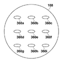
- FIG. 15 top view of the reagent cup 108
- nine external force applying lights respectively corresponding to nine points 360a to 360i are supplied to the reagent cup 108.
- An aspect in which the light is incident may be used. In this way, the range of solutions that can be irradiated with the external force imparting light increases, so the above problem can be avoided.
- the external force applying light is incident on nine points has been shown, but the number of points on which the external force applying light is incident is not limited to nine points, and may be more or less than nine points. It is desirable to make the light incident on more points as the external force imparting light is reduced. As a result, sudden fluctuations in fluorescence intensity can be reduced, and the coefficient of variation (Coefficient of Variation), which is an index representing relative dispersion, can be improved.
- Coefficient of Variation Coefficient of Variation
- FIG. 16 shows the structure of the external force applying light source unit 402 for allowing external force applying light to enter multiple points simultaneously from a predetermined direction.
- the external force imparting light source unit 402 is a 3 ⁇ 3 two-dimensional laser array.
- the external force applying light source unit 402 emits light from nine light emitting points 404a to 404i.
- the size of the light emitting point is 1 ⁇ m in the vertical direction and 100 ⁇ m in the horizontal direction.
- the distance between the light emitting points is about 100 ⁇ m.
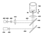
- FIG. 17 shows an example of an optical system using the external force applying light source unit 402 shown in FIG. In FIG. 17, components other than the optical system of the external force applying light and the excitation light are omitted.
- the external force applying light 422 output from the external force applying light source unit 402 passes through the collimator lens 406 and becomes a parallel light beam at the focal point.
- the external force imparting light 422 that has passed through the collimator lens 406 passes through the beam expander 408 and the beam expander 410.
- the external force imparting light 422 that has passed through the beam expander 408 and the beam expander 410 is spread into a parallel light beam having a specific magnification. Thereafter, the external force imparting light 422 is reflected by the dichroic mirror 418, collected by the lens 420, and incident upward from the bottom surface of the reagent cup 108.
- the excitation light 424 output from the light source unit 414 passes through the lens 426 and is reflected by the dichroic mirror 416.
- the excitation light 424 reflected by the dichroic mirror 416 passes through the dichroic mirror 418, is collected by the lens 420, and enters upward from the bottom surface of the reagent cup 108.
- the magnification is 1.29 times. Therefore, on the bottom surface of the reagent cup 108, the magnitude of the external force imparting light 422 is about 1.3 ⁇ m ⁇ 130 ⁇ m, and the pitch is about 129 ⁇ m.
- FIG. 18 As well, the optical system other than the external force applying light and excitation light is omitted. Also, the same components as those in FIG. 17 are denoted by the same reference numerals, and the description thereof is omitted.
- the external force imparting light source unit 116 is the same as that in the first embodiment.
- the external force imparting light 432 passes through the collimator lens 406, the beam expander 408, and the beam expander 410 and enters the microlens array 428.
- the microlens array 428 includes a plurality of microlenses 428a arranged in a lattice pattern.
- the external force imparted light 432 that has passed through the microlens array 428 becomes a plurality of light beams that are focused at different positions like light emitted from a plurality of light sources.
- the external force imparting light 432 is focused by the pinhole array 430, reflected by the dichroic mirror 418, passes through the lens 420, and enters upward from the bottom surface of the reagent cup 108. As described above, even when the microlens array is used, the external force applying light can be incident on multiple points simultaneously from a predetermined direction.
- the reagent cup has a cylindrical shape, but the reagent cup does not necessarily have a cylindrical shape.
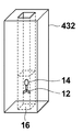
- a reagent cup 432 having a quadrangular prism shape and having a quadrangular prism-shaped solution holding portion inside may be used.
- the reagent cup 432 having such a rectangular column-shaped solution holding portion presses free molecules and binding molecules against the inner side wall surface of the reagent cup 432 using the pressure generated by the external force applying light acting in the traveling direction of the external force applying light. Suitable for cases.
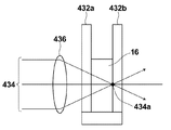
- FIG. 21 is a diagram illustrating an example of the positional relationship between the focal point of the collected external force application light and the reagent cup.
- the external force imparting light 434 enters the lens 436 and forms a focal point 434a at the interface between the plasma 16 and the side wall part 432b of the reagent cup (the inner side wall surface of the side wall part 432b).
- the intensity of the external force applying light 434 is the strongest, so that free molecules and binding molecules can be pressed with a stronger pressure. Therefore, when the external force imparting light 434 is incident as shown in FIG. 21, the Brownian motion of the free molecules and the binding molecules is more efficiently performed while pressing the free molecules and the binding molecules against the inner side wall surface of the side wall portion 432b at the position of the focal point 434a. Can be inhibited.
- the solution holding portion does not necessarily have a quadrangular prism shape, and it is sufficient that the solution holding portion has a flat surface on at least one surface. If the external force imparting light is irradiated so as to focus on the plane, the free molecules and the binding molecules move in a direction parallel to the plane and are pressed against the plane without going out of the external force imparted light irradiation range. However, the Brownian motion of these molecules is inhibited.
- the biomolecule detection apparatus and the biomolecule detection method according to the present invention perform detection or quantification of a detection target substance using, for example, an interaction between a detection target substance and a substance that specifically binds to the detection target substance. It can be used for a device to perform.
Landscapes
- Health & Medical Sciences (AREA)
- Chemical & Material Sciences (AREA)
- Physics & Mathematics (AREA)
- Immunology (AREA)
- Life Sciences & Earth Sciences (AREA)
- Analytical Chemistry (AREA)
- Nuclear Medicine, Radiotherapy & Molecular Imaging (AREA)
- Biochemistry (AREA)
- General Health & Medical Sciences (AREA)
- General Physics & Mathematics (AREA)
- Pathology (AREA)
- Optics & Photonics (AREA)
- Chemical Kinetics & Catalysis (AREA)
- Engineering & Computer Science (AREA)
- Biomedical Technology (AREA)
- Molecular Biology (AREA)
- Investigating, Analyzing Materials By Fluorescence Or Luminescence (AREA)
Abstract
La présente invention concerne un dispositif de détection de biomolécules pouvant effectuer des mesures de sensibilité élevée. En braquant un laser (117) sur une solution, une force extérieure est appliquée sur les molécules libres (13) et les molécules de liaison (15) dans ladite solution, ce qui permet d'inhiber le mouvement brownien desdites molécules libres (13) et molécules de liaison (15). En mesurant le mouvement brownien des molécules libres (13) et des molécules de liaison (15) dans la solution irradiée par un laser, la concentration d'un antigène fixé aux molécules de liaison (15) peut être mesurée précisément.
Priority Applications (1)
| Application Number | Priority Date | Filing Date | Title |
|---|---|---|---|
| US13/854,494 US20130224763A1 (en) | 2010-09-30 | 2013-04-01 | Biological molecule detecting apparatus and biological molecule detecting method |
Applications Claiming Priority (4)
| Application Number | Priority Date | Filing Date | Title |
|---|---|---|---|
| JP2010-223043 | 2010-09-30 | ||
| JP2010223043 | 2010-09-30 | ||
| JP2011123100A JP2012093338A (ja) | 2010-09-30 | 2011-06-01 | 生体分子検出装置および生体分子検出方法 |
| JP2011-123100 | 2011-06-01 |
Related Child Applications (1)
| Application Number | Title | Priority Date | Filing Date |
|---|---|---|---|
| US13/854,494 Continuation US20130224763A1 (en) | 2010-09-30 | 2013-04-01 | Biological molecule detecting apparatus and biological molecule detecting method |
Publications (1)
| Publication Number | Publication Date |
|---|---|
| WO2012042886A1 true WO2012042886A1 (fr) | 2012-04-05 |
Family
ID=45892375
Family Applications (1)
| Application Number | Title | Priority Date | Filing Date |
|---|---|---|---|
| PCT/JP2011/005498 Ceased WO2012042886A1 (fr) | 2010-09-30 | 2011-09-29 | Dispositif de détection de biomolécules et procédé de détection de biomolécules |
Country Status (3)
| Country | Link |
|---|---|
| US (1) | US20130224763A1 (fr) |
| JP (1) | JP2012093338A (fr) |
| WO (1) | WO2012042886A1 (fr) |
Families Citing this family (5)
| Publication number | Priority date | Publication date | Assignee | Title |
|---|---|---|---|---|
| JP5685492B2 (ja) * | 2010-09-30 | 2015-03-18 | 富士フイルム株式会社 | 生体分子検出装置および生体分子検出方法 |
| JP5703098B2 (ja) * | 2011-03-31 | 2015-04-15 | 富士フイルム株式会社 | 生体分子検出装置および生体分子検出方法 |
| JP6339024B2 (ja) | 2012-02-10 | 2018-06-06 | ザ ユニバーシティ オブ ノース カロライナ アット チャペル ヒルThe University Of North Carolina At Chapel Hill | 流体ナノファンネルを有する装置、関連する方法、製造及び解析システム |
| US9255288B2 (en) | 2013-03-13 | 2016-02-09 | The University Of North Carolina At Chapel Hill | Nanofluidic devices for the rapid mapping of whole genomes and related systems and methods of analysis |
| TWI614502B (zh) | 2017-07-26 | 2018-02-11 | 國立成功大學 | 分析物濃度的檢測方法 |
Citations (8)
| Publication number | Priority date | Publication date | Assignee | Title |
|---|---|---|---|---|
| JPS61272637A (ja) * | 1985-05-29 | 1986-12-02 | Hitachi Ltd | けい光偏光測定装置 |
| JPS6238346A (ja) * | 1985-08-14 | 1987-02-19 | Hitachi Ltd | 蛍光偏光測定装置 |
| JP2000019172A (ja) * | 1998-07-03 | 2000-01-21 | Matsushita Electric Ind Co Ltd | 多波長蛍光偏光法 |
| JP2003065930A (ja) * | 2001-08-28 | 2003-03-05 | Japan Science & Technology Corp | 複雑流体の局所粘弾性測定法及びその装置 |
| JP2003315258A (ja) * | 2002-04-23 | 2003-11-06 | Aisin Seiki Co Ltd | 微小物質誘導装置 |
| JP2005017282A (ja) * | 2003-05-30 | 2005-01-20 | Olympus Corp | 受光ユニットおよびそれを含む測定装置 |
| JP2006501860A (ja) * | 2002-05-22 | 2006-01-19 | プラティパス テクノロジーズ エルエルシー | 細胞をアッセイするための基体、装置および方法 |
| JP2010057364A (ja) * | 2006-12-26 | 2010-03-18 | Olympus Corp | 蛍光共鳴エネルギー移動を用いたdnaとdna結合性タンパク質の相互作用の検出方法 |
Family Cites Families (1)
| Publication number | Priority date | Publication date | Assignee | Title |
|---|---|---|---|---|
| US8383369B2 (en) * | 2008-09-24 | 2013-02-26 | Pacific Biosciences Of California, Inc. | Intermittent detection during analytical reactions |
-
2011
- 2011-06-01 JP JP2011123100A patent/JP2012093338A/ja not_active Withdrawn
- 2011-09-29 WO PCT/JP2011/005498 patent/WO2012042886A1/fr not_active Ceased
-
2013
- 2013-04-01 US US13/854,494 patent/US20130224763A1/en not_active Abandoned
Patent Citations (8)
| Publication number | Priority date | Publication date | Assignee | Title |
|---|---|---|---|---|
| JPS61272637A (ja) * | 1985-05-29 | 1986-12-02 | Hitachi Ltd | けい光偏光測定装置 |
| JPS6238346A (ja) * | 1985-08-14 | 1987-02-19 | Hitachi Ltd | 蛍光偏光測定装置 |
| JP2000019172A (ja) * | 1998-07-03 | 2000-01-21 | Matsushita Electric Ind Co Ltd | 多波長蛍光偏光法 |
| JP2003065930A (ja) * | 2001-08-28 | 2003-03-05 | Japan Science & Technology Corp | 複雑流体の局所粘弾性測定法及びその装置 |
| JP2003315258A (ja) * | 2002-04-23 | 2003-11-06 | Aisin Seiki Co Ltd | 微小物質誘導装置 |
| JP2006501860A (ja) * | 2002-05-22 | 2006-01-19 | プラティパス テクノロジーズ エルエルシー | 細胞をアッセイするための基体、装置および方法 |
| JP2005017282A (ja) * | 2003-05-30 | 2005-01-20 | Olympus Corp | 受光ユニットおよびそれを含む測定装置 |
| JP2010057364A (ja) * | 2006-12-26 | 2010-03-18 | Olympus Corp | 蛍光共鳴エネルギー移動を用いたdnaとdna結合性タンパク質の相互作用の検出方法 |
Non-Patent Citations (1)
| Title |
|---|
| MANN T L ET AL.: "Fluorescence polarization spectroscopy in protein analysis", ANALYST, vol. 128, no. 4, April 2003 (2003-04-01), pages 313 - 317 * |
Also Published As
| Publication number | Publication date |
|---|---|
| US20130224763A1 (en) | 2013-08-29 |
| JP2012093338A (ja) | 2012-05-17 |
Similar Documents
| Publication | Publication Date | Title |
|---|---|---|
| JP5734091B2 (ja) | 生体分子検出装置および生体分子検出方法 | |
| JP5703098B2 (ja) | 生体分子検出装置および生体分子検出方法 | |
| US8618508B2 (en) | Detection system and method | |
| CN103033497B (zh) | 一种应用拉曼光谱检测的微流控芯片分析仪 | |
| JP4709947B2 (ja) | Fret測定方法及び装置 | |
| JP5703126B2 (ja) | 生体分子検出装置および生体分子検出方法 | |
| JP5685492B2 (ja) | 生体分子検出装置および生体分子検出方法 | |
| WO2012042886A1 (fr) | Dispositif de détection de biomolécules et procédé de détection de biomolécules | |
| CN103913444A (zh) | 基于蓝光光镊的单光子激发荧光多通道定量检测装置及检测方法 | |
| JP5651061B2 (ja) | 生体分子検出装置および生体分子検出方法 | |
| JP6627778B2 (ja) | 検出装置および検出方法 | |
| JP6414205B2 (ja) | 表面プラズモン増強蛍光測定装置および表面プラズモン増強蛍光測定方法 | |
| WO2013031141A1 (fr) | Appareil et procédé de détection de molécules et cartouche pour détecter des molécules | |
| JP2012173252A (ja) | 蛍光分析装置および蛍光分析方法 | |
| JP2007155603A (ja) | 蛍光偏光解消法による分析方法 | |
| KR20150065149A (ko) | 면역분석 진단 장치 |
Legal Events
| Date | Code | Title | Description |
|---|---|---|---|
| 121 | Ep: the epo has been informed by wipo that ep was designated in this application |
Ref document number: 11828452 Country of ref document: EP Kind code of ref document: A1 |
|
| NENP | Non-entry into the national phase |
Ref country code: DE |
|
| 122 | Ep: pct application non-entry in european phase |
Ref document number: 11828452 Country of ref document: EP Kind code of ref document: A1 |