WO2012042947A1 - 船舶の空気潤滑システム - Google Patents
船舶の空気潤滑システム Download PDFInfo
- Publication number
- WO2012042947A1 WO2012042947A1 PCT/JP2011/057788 JP2011057788W WO2012042947A1 WO 2012042947 A1 WO2012042947 A1 WO 2012042947A1 JP 2011057788 W JP2011057788 W JP 2011057788W WO 2012042947 A1 WO2012042947 A1 WO 2012042947A1
- Authority
- WO
- WIPO (PCT)
- Prior art keywords
- air
- ship
- hole
- recovery
- side chamber
- Prior art date
- Legal status (The legal status is an assumption and is not a legal conclusion. Google has not performed a legal analysis and makes no representation as to the accuracy of the status listed.)
- Ceased
Links
Images


Classifications
-
- B—PERFORMING OPERATIONS; TRANSPORTING
- B63—SHIPS OR OTHER WATERBORNE VESSELS; RELATED EQUIPMENT
- B63B—SHIPS OR OTHER WATERBORNE VESSELS; EQUIPMENT FOR SHIPPING
- B63B1/00—Hydrodynamic or hydrostatic features of hulls or of hydrofoils
- B63B1/32—Other means for varying the inherent hydrodynamic characteristics of hulls
- B63B1/34—Other means for varying the inherent hydrodynamic characteristics of hulls by reducing surface friction
- B63B1/38—Other means for varying the inherent hydrodynamic characteristics of hulls by reducing surface friction using air bubbles or air layers gas filled volumes
-
- B—PERFORMING OPERATIONS; TRANSPORTING
- B63—SHIPS OR OTHER WATERBORNE VESSELS; RELATED EQUIPMENT
- B63B—SHIPS OR OTHER WATERBORNE VESSELS; EQUIPMENT FOR SHIPPING
- B63B1/00—Hydrodynamic or hydrostatic features of hulls or of hydrofoils
- B63B1/32—Other means for varying the inherent hydrodynamic characteristics of hulls
- B63B1/34—Other means for varying the inherent hydrodynamic characteristics of hulls by reducing surface friction
- B63B1/38—Other means for varying the inherent hydrodynamic characteristics of hulls by reducing surface friction using air bubbles or air layers gas filled volumes
- B63B2001/387—Other means for varying the inherent hydrodynamic characteristics of hulls by reducing surface friction using air bubbles or air layers gas filled volumes using means for producing a film of air or air bubbles over at least a significant portion of the hull surface
-
- Y—GENERAL TAGGING OF NEW TECHNOLOGICAL DEVELOPMENTS; GENERAL TAGGING OF CROSS-SECTIONAL TECHNOLOGIES SPANNING OVER SEVERAL SECTIONS OF THE IPC; TECHNICAL SUBJECTS COVERED BY FORMER USPC CROSS-REFERENCE ART COLLECTIONS [XRACs] AND DIGESTS
- Y02—TECHNOLOGIES OR APPLICATIONS FOR MITIGATION OR ADAPTATION AGAINST CLIMATE CHANGE
- Y02T—CLIMATE CHANGE MITIGATION TECHNOLOGIES RELATED TO TRANSPORTATION
- Y02T70/00—Maritime or waterways transport
- Y02T70/10—Measures concerning design or construction of watercraft hulls
-
- Y—GENERAL TAGGING OF NEW TECHNOLOGICAL DEVELOPMENTS; GENERAL TAGGING OF CROSS-SECTIONAL TECHNOLOGIES SPANNING OVER SEVERAL SECTIONS OF THE IPC; TECHNICAL SUBJECTS COVERED BY FORMER USPC CROSS-REFERENCE ART COLLECTIONS [XRACs] AND DIGESTS
- Y10—TECHNICAL SUBJECTS COVERED BY FORMER USPC
- Y10T—TECHNICAL SUBJECTS COVERED BY FORMER US CLASSIFICATION
- Y10T29/00—Metal working
- Y10T29/49—Method of mechanical manufacture
- Y10T29/49716—Converting
Definitions
- the present invention relates to a technique for reducing resistance between a ship and water by supplying air bubbles.
- This application claims priority based on Japanese Patent Application No. 2010-216125 filed on Sep. 27, 2010, the entire disclosure of which is incorporated herein.
- An air lubrication system is known as a technique for improving the efficiency of ship navigation.
- the air lubrication system is a technology that reduces the friction between the ship and water by supplying bubbles to the outer surface below the waterline of the hull, and improves navigation efficiency.
- the technique described in Japanese Patent Laid-Open No. 2009-248831 is an example.
- the inventor of the present invention is developing a technology for improving navigation efficiency by refurbishing an existing ship with an external air lubrication system. In such a technique, it is desired that refurbishment is easy and the effect of reducing frictional resistance is great.
- an air blowing device is attached to the bottom of a ship and has a blow-out side chamber having an air blow-out hole on a surface opposed to the bottom of the ship bottom, and supplies air to the inside of the blow-out side chamber. And a supply unit.
- the supply unit is arranged at a different position in the front-rear direction of the ship with respect to the air blowing hole.
- the supply unit of the air blowing device supplies air to the internal space from an air supply hole formed on the ship bottom side of the ship with respect to the air blowing hole.
- the blow-out side chamber has an air diffusion portion extending in the front-rear direction of the ship for diffusing the air supplied by the supply portion between the air supply hole and the air blow-out hole.
- the air blowing holes of the air blowing device are distributed in a wider area in the lateral direction of the ship than the air supply holes.
- the air blowing device is further installed at a position on the stern side with respect to the air supply hole in the internal space and on the bow side with respect to the air blowing hole, and diffuses air supplied from the air supply hole. And a diffusion member to be supplied to the air blowing hole side.
- a ship in one aspect of the present invention, includes an air blowing device according to the present invention at the bottom of the ship.
- an air lubrication system includes an air blowing device according to the present invention and an air recovery device.
- the air recovery device is attached to the bottom of the stern side of the air blowing device, and collects the air inside the recovery side chamber, the recovery side chamber having an air intake hole on the surface facing the lower side with respect to the ship bottom.
- a recovery unit a recovery unit.
- the recovery unit of the air recovery device recovers the air inside the recovery side chamber from the air recovery hole formed in the bottom of the stern of the ship with respect to the air intake hole.
- the collection-side chamber has an air accumulation part that extends in the front-rear direction of the ship for collecting air collected from the air intake hole and collecting it from the air collection hole.
- the air intake holes of the air recovery device are distributed in a wider area in the lateral direction of the ship than the air recovery holes.
- the air recovery device is further disposed inside the recovery side chamber, and is a guide plate that is inclined from the surface facing the air recovery hole toward the air recovery hole toward the ship bottom. Is provided.
- the recovery side chamber of the air recovery device has a shape symmetrical to that of the blowout side chamber of the air blowing device with respect to a predetermined reference line facing in the lateral direction of the ship.
- a ship in one aspect of the present invention, includes an air lubrication system according to the present invention at the bottom of the ship.
- a method for refurbishing a ship includes a step of attaching a blowout side chamber having an air blowout hole to a bottom surface of a ship, the surface facing the bottom of the ship bottom, and air inside the blowout side chamber. Forming a supply unit to be supplied.
- the supply unit is arranged at a different position in the front-rear direction of the ship with respect to the air blowing hole.
- the ship refurbishment method further includes a step of attaching a recovery side chamber having an air intake hole on a surface facing the lower side with respect to the bottom of the ship, on the bottom of the stern side of the air blowing device. And a step of forming a recovery unit that recovers the air inside the recovery side chamber.
- the present invention provides an air blowing device, an air lubrication system, and a ship refurbishing method that have a great effect of reducing frictional resistance. Furthermore, the present invention provides an air blowing device, an air lubrication system, and a ship refurbishing method that are relatively easy to refurbish in an air lubrication system externally attached to a ship.
- FIG. 1 is a side view of a ship.
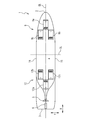
- FIG. 2 is a bottom view of the ship.
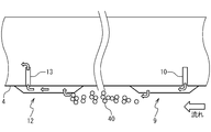
- FIG. 3 schematically illustrates the operation of the air lubrication system.
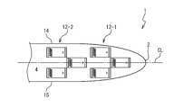
- FIG. 4 shows another configuration example of the blowout side chamber.
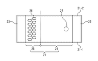
- FIG. 5 is a bottom view of the blowout side chamber.
- FIG. 6 is a cross-sectional view of the blowout side chamber as seen from the side.
- FIG. 7 is a bottom view of the collection side chamber.
- FIG. 8 is a cross-sectional view of the collection-side chamber as viewed from the side.
- FIG. 9 is a bottom view of the collection-side chamber provided with the narrowing portion.
- FIG. 10 is a cross-sectional view of the collection-side chamber provided with the narrowing portion as seen from the side.
- FIG. 1 is a side view of a ship to which an air blowing device, an air lubrication system, and a refurbishing method according to an embodiment of the present invention are applied.
- FIG. 2 is a bottom view of the ship as seen from the bottom side. The bow 2 of the hull 1 is drawn on the right side and the stern 3 is drawn on the left side. A propeller 5 and a rudder 6 are installed below the draft line on the stern 3 side. An air blowing device 7 is installed on the side of the ship bottom 4 close to the bow 2. An air recovery device 8 is installed on the side of the ship bottom 4 close to the stern 3.
- the air blowing device 7 includes a blowing side chamber 9 installed on the ship bottom 4, a pipe 10, and a compressor 11.
- a blower may be used instead of the compressor 11.
- the compressor 11 pushes the air inside the pipe 10 toward the ship bottom 4.
- One end of the pipe 10 is connected to an air supply hole (described later) formed in the outer wall of the ship bottom 4.
- the blowout side chamber 9 is attached to the bottom 4 of the position where the air supply hole opens by welding or bolt fastening. Air inside the pipe 10 is supplied into the chamber 9 by the compressor 11.
- the air recovery device 8 includes a recovery side chamber 12 and a pipe 13. One end of the pipe 13 is connected to an air recovery hole (described later) formed in the outer wall of the ship bottom 4.
- the recovery side chamber 12 is attached to the ship bottom 4 at the position where the air recovery hole is opened by welding or bolt fastening.
- the air inside the collection side chamber 12 is discharged to the outside through the pipe 13 or is resupplied to the pipe 10 on the air blowing device 7 side.
- blowout side chamber 9a on the front row side is mounted on the center line CL of the hull 1 in line symmetry with respect to the center line CL.
- One of the blow-out side chambers 9b on the rear row side is attached in parallel to a position biased toward the starboard 14 side with respect to the blow-out side chamber 9a on the front row side.
- the other is attached in parallel to a position deviated toward the port 15 side with respect to the blowout side chamber 9a on the front row side, and forms a blowout side chamber 9b on the back row side symmetrical with respect to the center line CL.
- a plurality of recovery side chambers 12 are attached corresponding to the blowout side chamber 9.
- the collection-side chambers 12a and 12b on the rear row side and the front row side are attached, respectively.
- Each collection side chamber 12 has the same shape as the blowout side chamber 9 and is installed in the direction reversed in the front-rear direction of the hull 1.
- the blowout side chamber 9 and the recovery side chamber 12 have a line-symmetric configuration with respect to a predetermined reference line SL extending in the lateral direction of the hull 1.
- FIG. 3 schematically shows the operation of the air lubrication system.
- Air is supplied from the pipe 10 to the blowout side chamber 9.
- the blowout side chamber 9 blows the air into the outside water as bubbles 40.
- the bubble 40 flows to the stern 3 side covering the bottom 4. Since the ship bottom 4 is covered with the bubbles 40, friction between the hull 1 and water is reduced.
- the bubble 40 is taken into the collection side chamber 12 and collected from the pipe 13.
- FIG. 4 shows another configuration example of the blowout side chamber 9.
- the bubbles 40 are provided so as to substantially cover the width of the ship bottom 4 by the three outlet side chambers 9.
- FIG. 4 in addition to a group of three outlet side chambers 12-1 that substantially cover the width of the ship bottom 4, three outlets having a similar configuration at a position shifted in the length direction of the hull 1.
- a group of side chambers 12-2 is installed. In this configuration example, a larger number of bubbles 40 can be supplied to the ship bottom 4.
- the bubbles 40 are likely to escape from the left and right direction of the ship bottom 4, when the bubbles 40 supplied from the blowing side chamber 12-1 are insufficient on the stern 3 side, the bubbles 40 are discharged from the blowing side chamber 12-2 at the next stage. Can be supplemented. In such a case, by installing a group of collection side chambers having a configuration symmetrical with respect to the plurality of groups of blowout side chambers 12-1 and 12-2 and a predetermined reference line SL on the stern 3 side, Can be recovered.
- FIG. 5 is a bottom view of the blowout side chamber 9.
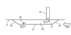
- FIG. 6 is a sectional view of the blowout side chamber 9 as seen from the side. In either case, the right side of the figure is the bow 2 side.
- the blow-out side chamber 9 includes a flat portion 21, a front end portion 22, a rear end portion 23, and side plates 21-1 and 21-2.
- the flat portion 21 is a plate-like member installed below the ship bottom 4.
- the flat portion 21 faces the ship bottom 4 and is arranged so as to be parallel to or close to the ship bottom 4. In the example of FIG. 6, the flat portion 21 is disposed in parallel with the ship bottom 4.
- the front end portion 22 is a plate-like member that connects the end portion of the flat portion 21 on the bow 2 side and the ship bottom 4.
- the front end 22 has an inclination that approaches the ship bottom 4 toward the bow 2 in order to reduce the resistance of water flow when the hull 1 sails forward.
- the rear end portion 23 is a plate-like member that connects the end portion of the flat portion 21 on the stern 3 side and the ship bottom 4.
- the rear end portion 23 has an inclination that approaches the stern 3 toward the stern 3 in order to suppress the generation of vortices that become resistance when the hull 1 navigates forward, and to smoothly introduce the bubbles to the bottom 4.
- the side plate 21-1 closes between the port side ends of the flat portion 21, the front end portion 22, and the rear end portion 23 and the bottom 4 of the ship.
- the side plate 21-2 closes the space between the starboard side ends of the flat portion 21, the front end portion 22, and the rear end portion 23 and the ship bottom 4.
- a bubble chamber 28 is formed by the flat portion 21, the front end portion 22, the rear end portion 23, the side plates 21-1 and 21-2, and the ship bottom 4 covered by them.
- the bubble chamber 28 is a closed space that communicates with water below the surface of the water in which the hull 1 floats in the air blowing hole 26, communicates with the pipe 10 in the air supply hole 27, and is otherwise closed.
- the flat portion 21 is divided into an air diffusing portion 24 that is a region on the bow 2 side and an air blowing portion 25 that is a region on the stern 3 side, with the dotted line in FIG.
- a plurality of air blowing holes 26 are formed in the air blowing portion 25. These air blowing holes 26 are formed side by side in the width direction of the hull 1, for example. In the example of FIG. 5, two rows of air blowing holes 26 are arranged in a staggered manner in the length direction of the hull 1.
- An air supply hole 27 is formed at a position (a position on the bow 2 side in FIGS. 5 and 6) of the ship bottom 4 facing the air diffusion portion 24, which is different from the air blowing hole 26.
- One end of the pipe 10 is connected to the air supply hole 27.
- the air diffusion portion 24 provides a predetermined distance in the front-rear direction of the hull 1 between the air supply hole 27 and the air supply hole 26. Due to this distance, the air supplied from the air supply hole 27 to the bubble chamber 28 is diffused, and the bubbles are blown out into the water in a nearly uniform amount from the plurality of air blowing holes 26 arranged in the width direction of the hull 1. It becomes possible.
- it is desirable that the distance between the center of the air supply hole 27 and the center of the air blowing hole 26 is set to be longer than the width of the bubble chamber 28. .
- the air supplied from the air supply hole 27 to the bubble chamber 28 is impinged on the upper surface (inner wall surface) of the flat portion 21 by the pressure applied by the compressor 11. Due to the pressure of the impingement, the supplied air becomes fine bubbles, and the width of the distribution is easily widened. The bubbles are spread in the width direction while being pushed downstream in the air diffusion section 24.
- the width of the air supply hole 27 can be made smaller than the width of the horizontal distribution of the hull of the air blowing holes 26.
- the air diffusing portion 24 even when the number of the air supply holes 27 is small (one in the example of FIG. 5), the air blowing holes 26 are distributed in a wide area in the lateral direction of the hull 1.
- the bubbles 40 can be blown out with a distribution nearly uniform in the width direction. Therefore, when retrofitting a ship and retrofitting an air lubrication system, the labor for constructing the air supply hole 27 and the pipe 10 in the hull 1 can be reduced.
- a diffusion member for diffusing bubbles can be added to the blowout side chamber 9.
- a perforated plate so that the bubble chamber 28 is partitioned between the air supply hole 27 and the air blowing hole 26 in the front-rear direction of the hull 1, finer bubbles can be supplied to the air blowing hole 26. is there.
- the bubble 40 When a certain amount of air accumulates inside the bubble chamber 28, the bubble 40 is pushed out from the air blowing hole 26 into the water under the ship bottom 4. While the ship is sailing, the hull 1 propels forward against the water. In the ship bottom 4, the water flow has a main direction from the front end portion 22 side to the rear end portion 23 side of the blowout side chamber 9. On the other hand, since the inside of the blowout side chamber 9 is a relatively closed space, the flow of water and air in the bubble chamber 28 is gentle compared to the external water flow. Therefore, when the air in the bubble chamber 28 blows out from the air blowing hole 26, the bubbles are sheared by the shearing force of the water flow and flow into the downstream side as finer bubbles 40.
- the fine bubbles 40 stay on the ship bottom 4 for a long time, a high air lubrication effect can be obtained.
- the air from the air supply hole 27 is not supplied to the ship bottom 4 as it is, but is temporarily retained inside the bubble chamber 28 by the rear end portion 23 and the like, and then supplied to the outside so that a shearing force works. By doing so, the bubble 40 suitable for air lubrication is obtained.
- each air outlet 26 has an oval shape that is long in the main flow direction, that is, in the front-rear direction of the hull 1.
- the bubble 40 blown out from the air blowing hole 26 rises along the rear end 23, flows to the stern 3 side while covering the ship bottom 4, and reaches the air recovery side chamber 12.
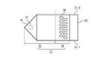
- FIG. 7 is a bottom view of the collection side chamber 12.
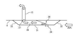
- FIG. 8 is a sectional view of the collection side chamber 12 as seen from the side. In either case, the right side of the figure is the bow 2 side.
- the collection side chamber 9 has the same shape as the blowout side chamber 9 and is attached to the ship bottom 4 in the direction opposite to the front-rear direction of the hull 1.
- the collection side chamber 12 includes a flat portion 31, a front end portion 32, a rear end portion 33, and side plates 31-1, 31-2.
- the flat portion 31 is a plate-like member installed on the lower side of the ship bottom 4 and is disposed in parallel to face the ship bottom 4.
- the front end portion 32 is a plate-like member that connects the end portion of the flat portion 31 on the bow 2 side and the ship bottom 4.
- the front end portion 32 has an inclination that approaches the ship bottom 4 toward the bow 2 side in order to reduce resistance to water flow when the hull 1 sails forward.
- the rear end portion 33 is a plate-like member that connects the end portion of the flat portion 31 on the stern 3 side and the ship bottom 4.
- the rear end portion 33 has an inclination that approaches the stern 3 toward the stern 3 in order to suppress generation of a vortex that becomes resistance when the hull 1 sails forward.
- the side plates 31-1 and 31-2 close the left and right sides of the recovery side chamber 12 and form bubble chambers 38, like the side plates 21-1 and 21-2 of the blowout side chamber.
- the bubble chamber 38 is a space that communicates with water below the water surface where the hull 1 floats in the air intake hole 36, communicates with the pipe 13 in the air recovery hole 37, and is otherwise closed.
- the recovery-side chamber 12 having such a configuration can be realized by installing the member for the blow-out side chamber 9 on the ship bottom 4 so as to be reversed in the front-rear direction of the hull 1.
- the flat part 31 is divided into an air intake part 34 which is an area on the bow 2 side and an extrusion pressure generating part 35 which is an area on the stern 3 side with the dotted line in FIG. It is done.
- a plurality of air intake holes 36 are formed in the air intake portion 34 in the same manner as the air outlet holes 26 of the outlet side chamber 9.
- An air recovery hole 37 is formed in the ship bottom 4 facing the extrusion pressure generator 34.
- One end of the pipe 13 is connected to the air recovery hole 37.
- a bubble chamber 38 having a certain volume can be obtained by the extrusion pressure generator 35. Bubbles taken in from the air intake hole 36 accumulate in the bubble chamber. The air bubbles once accumulate in the extrusion pressure generating unit 35, so that a certain amount of air mass is accumulated in the air bubble chamber 38. As a result, the bubbles can be smoothly recovered from the air recovery hole 37.
- the collection-side chamber 12 is thin.
- the length of the extrusion pressure generating portion 35 large, a sufficient volume of the bubble chamber 38 can be obtained even if the collection side chamber 12 is thin. Therefore, for example, it is desirable to set the center of the air intake hole 36 and the center of the air recovery hole 37 to be longer than the width of the bubble chamber 38 as in the case of the blowout side chamber 9.
- the bubbles 40 can be taken in more smoothly.
- the guide plate 39 is grounded inside the collection side chamber 12 at a position overlapping the air intake hole 36 when viewed in the vertical direction.
- the guide plate 39 is tilted so as to approach the ship bottom 4 from the bow 2 side toward the stern 3 side.
- the air bubbles 40 taken in from the air take-in hole 36 are smoothly fed into the extrusion pressure generator 35.
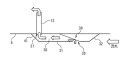
- FIG. 9 and FIG. 10 are a bottom view and a cross-sectional view showing a recovery side chamber in a modification of the present embodiment.
- the collection side chamber includes a narrowing portion 41 at the downstream end thereof.
- the collection side chamber is narrowed so that the width of the collection side chamber gradually decreases toward the downstream side.
- the narrowing portion 41 is preferably formed of a plate material that is closer to the ship bottom 4 toward the downstream side, similarly to the rear end portion 33 of FIG.
- the air recovery hole 37 is located at the upper part of the narrowing portion 41 in the vertical direction. With such a configuration, the air bubbles taken into the air bubble chamber 38 are easily collected in the narrowing portion 41, and the air bubbles can be recovered from the air recovery holes 37 more efficiently.
- an air supply hole 27 and an air recovery hole 37 are formed in the ship bottom 4.
- the pipe 10, the pipe 13, and the compressor 11 are installed in the ship.
- a blowout side chamber 9 and a recovery side chamber 12 are installed on the ship bottom 4. In this way, the efficiency of navigation of existing ships can be improved. Also when installing the air lubrication system in this embodiment with respect to a new ship, an air lubrication system can be installed with few design changes by the same procedure.
- the configuration of the air lubrication system in this embodiment is effective even if only the air blowing device 7 side is used.
- it is an internal type in which a chamber for air bubble recovery is formed inside the hull 1, and the blowout side chamber 9 is externally attached. The same effect as this embodiment can be acquired.
Landscapes
- Physics & Mathematics (AREA)
- Fluid Mechanics (AREA)
- Chemical & Material Sciences (AREA)
- Engineering & Computer Science (AREA)
- Combustion & Propulsion (AREA)
- Mechanical Engineering (AREA)
- Ocean & Marine Engineering (AREA)
- Cleaning Or Clearing Of The Surface Of Open Water (AREA)
- Aeration Devices For Treatment Of Activated Polluted Sludge (AREA)
Abstract
Description
更に本発明により、船舶に外付けされる空気潤滑システムにおいて、改装が比較的容易な空気吹き出し装置、空気潤滑システム及び船舶の改装方法が提供される。
Claims (15)
- 船舶の船底に取り付けられ、前記船底に対して下側に対向する面に空気吹出孔を有する吹出側チャンバーと、
前記吹出側チャンバーの内部に空気を供給する供給部と
を具備する空気吹き出し装置。 - 請求項1に記載された空気吹き出し装置であって、
前記供給部は、前記空気吹出孔に対して前記船舶の前後方向に異なる位置に配置される
空気吹き出し装置。 - 請求項1又は2に記載された空気吹き出し装置であって、
前記供給部は、前記空気吹出孔よりも前記船舶の船首側の前記船底に形成された空気供給孔から前記内部空間に空気を供給し、
前記吹出側チャンバーは、前記空気供給孔と前記空気吹出孔との間に、前記供給部が供給する空気を拡散するための前記船舶の前後方向に延長する空気拡散部を有する
空気吹き出し装置。 - 請求項3に記載された空気吹き出し装置であって、
前記空気吹出孔は、前記空気供給孔よりも前記船舶の横方向に広い領域に分布する
空気吹き出し装置。 - 請求項3又は4に記載された空気吹き出し装置であって、
更に、前記内部空間の前記空気供給孔よりも船尾側で且つ前記空気吹出孔よりも船首側の位置に設置され、前記空気供給孔から供給される空気を拡散して前記空気吹出孔側に供給する拡散部材
を具備する空気吹き出し装置。 - 請求項1から5のいずれか1項に記載された空気吹き出し装置を船底に備えた船舶。
- 請求項1から5のいずれか1項に記載された空気吹き出し装置と、
空気回収装置とを具備する空気潤滑システムであって、
前記空気回収装置は、
前記空気吹き出し装置よりも船尾側の前記船底に取り付けられ、前記船底に対して下側に対向する面に空気取込孔を有する回収側チャンバーと、
前記回収側チャンバーの内部の空気を回収する回収部とを具備する
空気潤滑システム。 - 請求項7に記載された空気潤滑システムであって、
前記回収部は、前記空気取込孔よりも前記船舶の船尾側の前記船底に形成された空気回収孔から前記回収側チャンバーの内部の空気を回収し、
前記回収側チャンバーは、前記空気取込孔から取り込まれた空気を集めて前記空気回収孔から回収するための前記船舶の前後方向に延長する空気蓄積部を有する
空気潤滑システム。 - 請求項8に記載された空気潤滑システムであって、
前記空気取入孔は、前記空気回収孔よりも前記船舶の横方向に広い領域に分布する
空気潤滑システム。 - 請求項8又は9に記載された空気潤滑システムであって、
更に、前記回収側チャンバーの内部に配置され、前記空気取込孔から前記空気回収孔の方に向って前記対向する面から前記船底に向うように傾斜する案内板
を具備する空気潤滑システム。 - 請求項8から10のいずれか1項に記載された空気潤滑システムであって、
前記回収側チャンバーは、船舶の横方向を向く所定の基準線について、前記空気吹き出し装置の前記吹出側チャンバーと対称的な形状を有する
空気潤滑システム。 - 請求項8から11のいずれか1項に記載された空気潤滑システムを船底に備えた船舶。
- 船舶の船底に、前記船底に対して下側に対向する面に空気吹出孔を有する吹出側チャンバーを取り付ける工程と、
前記吹出側チャンバーの内部に空気を供給する供給部を形成する工程と
を具備する船舶の改装方法。 - 請求項13に記載された船舶の改装方法であって、
前記供給部は、前記空気吹出孔に対して前記船舶の前後方向に異なる位置に配置される
船舶の改装方法。 - 請求項13又は14に記載された船舶の改装方法であって、
更に、前記空気吹き出し装置よりも船尾側の前記船底に、前記船底に対して下側に対向する面に空気取込孔を有する回収側チャンバーを取り付ける工程と、
前記回収側チャンバーの内部の空気を回収する回収部を形成する工程と
を具備する船舶の改装方法。
Priority Applications (4)
| Application Number | Priority Date | Filing Date | Title |
|---|---|---|---|
| CN201180032233.4A CN102958793B (zh) | 2010-09-27 | 2011-03-29 | 船舶的空气润滑系统 |
| KR1020127034014A KR101508048B1 (ko) | 2010-09-27 | 2011-03-29 | 선박의 공기 윤활 시스템 |
| EP11828509.7A EP2623410B1 (en) | 2010-09-27 | 2011-03-29 | Air lubrication system for ship |
| US13/806,410 US9102383B2 (en) | 2010-09-27 | 2011-03-29 | Air lubrication system of ship |
Applications Claiming Priority (2)
| Application Number | Priority Date | Filing Date | Title |
|---|---|---|---|
| JP2010216125A JP2012071632A (ja) | 2010-09-27 | 2010-09-27 | 船舶の空気潤滑システム |
| JP2010-216125 | 2010-09-27 |
Publications (1)
| Publication Number | Publication Date |
|---|---|
| WO2012042947A1 true WO2012042947A1 (ja) | 2012-04-05 |
Family
ID=45892430
Family Applications (1)
| Application Number | Title | Priority Date | Filing Date |
|---|---|---|---|
| PCT/JP2011/057788 Ceased WO2012042947A1 (ja) | 2010-09-27 | 2011-03-29 | 船舶の空気潤滑システム |
Country Status (6)
| Country | Link |
|---|---|
| US (1) | US9102383B2 (ja) |
| EP (1) | EP2623410B1 (ja) |
| JP (1) | JP2012071632A (ja) |
| KR (1) | KR101508048B1 (ja) |
| CN (1) | CN102958793B (ja) |
| WO (1) | WO2012042947A1 (ja) |
Cited By (1)
| Publication number | Priority date | Publication date | Assignee | Title |
|---|---|---|---|---|
| JP2017043134A (ja) * | 2015-08-24 | 2017-03-02 | 住友重機械マリンエンジニアリング株式会社 | 空気潤滑システムの空気発生装置 |
Families Citing this family (12)
| Publication number | Priority date | Publication date | Assignee | Title |
|---|---|---|---|---|
| PL2915735T3 (pl) * | 2014-03-05 | 2017-01-31 | Silverstream Technologies B.V. | System smarowania powietrznego i jednostka pływająca zawierająca taki system |
| JP2017507072A (ja) * | 2014-03-05 | 2017-03-16 | シルバーストリーム・テクノロジーズ・ビー.ブイ. | 船上の海洋生成物付着を低減するための空気潤滑システムの使用 |
| KR101630574B1 (ko) | 2014-04-02 | 2016-06-15 | 현대중공업 주식회사 | 선박의 바닥판에서 해수에 돌출되는 공기분사장치 |
| CN106335597B (zh) * | 2015-07-06 | 2019-03-29 | 现代重工业株式会社 | 船舶空气润滑装置 |
| JP2018535144A (ja) * | 2015-12-04 | 2018-11-29 | サムスン・ヘヴィー・インダストリーズ・カンパニー・リミテッド | 摩擦抵抗低減装置及びこれを含む船舶 |
| DE102016207977A1 (de) | 2016-05-10 | 2017-05-11 | Voith Patent Gmbh | Laufrad für eine hydraulische Maschine |
| PL3290325T3 (pl) * | 2016-08-30 | 2019-11-29 | Silverstream Tech Bv | Układ smarowania powietrznego z deflektorem fal dla statku wodnego |
| KR101893508B1 (ko) * | 2017-02-10 | 2018-08-30 | 부산대학교 산학협력단 | 압력구배를 이용한 선박의 공기 윤활 방법 |
| KR102707023B1 (ko) * | 2018-12-28 | 2024-09-13 | 한화오션 주식회사 | 공기챔버 및 공기챔버를 포함하는 선박의 공기 윤활 시스템 |
| USD919544S1 (en) * | 2019-05-29 | 2021-05-18 | Silverstream Technologies B.V. | Air release unit |
| KR20230097040A (ko) * | 2020-10-01 | 2023-06-30 | 메르스크 에이/에스 | 선박의 선체를 위한 공기 공급 시스템, 및 공기 공급 시스템을 포함하는 선박 |
| USD1091803S1 (en) * | 2021-12-27 | 2025-09-02 | Parker Maritime Technologies, LLC | Compressor-free air lubrication system |
Citations (4)
| Publication number | Priority date | Publication date | Assignee | Title |
|---|---|---|---|---|
| JP2001524421A (ja) * | 1997-12-02 | 2001-12-04 | ダニエル・ジェイ・ウイッパー | 船舶の船体に生じる水摩擦を低減するためのエネルギ効率化装置 |
| JP2009248611A (ja) * | 2008-04-01 | 2009-10-29 | National Maritime Research Institute | 船舶の摩擦抵抗低減装置 |
| JP2009248831A (ja) | 2008-04-08 | 2009-10-29 | National Maritime Research Institute | 船舶の気泡巻き込み防止装置 |
| JP2010120607A (ja) * | 2008-11-21 | 2010-06-03 | Mitsubishi Heavy Ind Ltd | 船体摩擦抵抗低減装置 |
Family Cites Families (8)
| Publication number | Priority date | Publication date | Assignee | Title |
|---|---|---|---|---|
| US1697257A (en) * | 1928-01-10 | 1929-01-01 | Anissimoff Boris | Device for reducing the skin and wave resistance of moving boats |
| US3084651A (en) * | 1950-05-23 | 1963-04-09 | Parmenter Richard | Silencer for ships |
| US3289623A (en) * | 1965-03-09 | 1966-12-06 | Exxon Research Engineering Co | Frictional resistance reduction using non-newtonian fluid |
| US3650235A (en) * | 1969-07-31 | 1972-03-21 | Veritas International | Hull construction |
| JP2000296795A (ja) * | 1999-04-13 | 2000-10-24 | Ishikawajima Harima Heavy Ind Co Ltd | 摩擦抵抗低減船 |
| DE10307795B4 (de) * | 2003-02-24 | 2005-10-06 | New-Logistics Gmbh | Verdrängungskörper, insbesondere Wasserfahrzeug oder Schiff, und Verfahren zur Reibungsverminderung bei Verdrängungskörpern |
| CN105501388A (zh) | 2008-04-01 | 2016-04-20 | 国立研究开发法人海上技术安全研究所 | 船舶的摩擦阻力减小装置 |
| JP2009274713A (ja) | 2008-04-15 | 2009-11-26 | Ouchi Ocean Consultant Inc | 気泡潤滑船 |
-
2010
- 2010-09-27 JP JP2010216125A patent/JP2012071632A/ja not_active Withdrawn
-
2011
- 2011-03-29 EP EP11828509.7A patent/EP2623410B1/en not_active Not-in-force
- 2011-03-29 WO PCT/JP2011/057788 patent/WO2012042947A1/ja not_active Ceased
- 2011-03-29 KR KR1020127034014A patent/KR101508048B1/ko not_active Expired - Fee Related
- 2011-03-29 CN CN201180032233.4A patent/CN102958793B/zh not_active Expired - Fee Related
- 2011-03-29 US US13/806,410 patent/US9102383B2/en not_active Expired - Fee Related
Patent Citations (4)
| Publication number | Priority date | Publication date | Assignee | Title |
|---|---|---|---|---|
| JP2001524421A (ja) * | 1997-12-02 | 2001-12-04 | ダニエル・ジェイ・ウイッパー | 船舶の船体に生じる水摩擦を低減するためのエネルギ効率化装置 |
| JP2009248611A (ja) * | 2008-04-01 | 2009-10-29 | National Maritime Research Institute | 船舶の摩擦抵抗低減装置 |
| JP2009248831A (ja) | 2008-04-08 | 2009-10-29 | National Maritime Research Institute | 船舶の気泡巻き込み防止装置 |
| JP2010120607A (ja) * | 2008-11-21 | 2010-06-03 | Mitsubishi Heavy Ind Ltd | 船体摩擦抵抗低減装置 |
Non-Patent Citations (1)
| Title |
|---|
| See also references of EP2623410A4 * |
Cited By (1)
| Publication number | Priority date | Publication date | Assignee | Title |
|---|---|---|---|---|
| JP2017043134A (ja) * | 2015-08-24 | 2017-03-02 | 住友重機械マリンエンジニアリング株式会社 | 空気潤滑システムの空気発生装置 |
Also Published As
| Publication number | Publication date |
|---|---|
| CN102958793B (zh) | 2016-02-17 |
| CN102958793A (zh) | 2013-03-06 |
| US9102383B2 (en) | 2015-08-11 |
| EP2623410A4 (en) | 2014-11-05 |
| EP2623410B1 (en) | 2016-10-19 |
| US20130139746A1 (en) | 2013-06-06 |
| KR20130019439A (ko) | 2013-02-26 |
| EP2623410A1 (en) | 2013-08-07 |
| KR101508048B1 (ko) | 2015-04-07 |
| JP2012071632A (ja) | 2012-04-12 |
Similar Documents
| Publication | Publication Date | Title |
|---|---|---|
| JP5705486B2 (ja) | 船舶の空気潤滑システム | |
| WO2012042947A1 (ja) | 船舶の空気潤滑システム | |
| US8011310B2 (en) | Ship with reduced frictional resistance and its operation method | |
| US5967071A (en) | Energy efficient system and method for reducing water friction on the hull of a marine vessel | |
| EP2554469B1 (en) | Ship encountering less frictional resistance | |
| JP5022344B2 (ja) | 船体摩擦抵抗低減装置 | |
| CN102448807B (zh) | 船舶的降低阻力装置 | |
| CN103459245B (zh) | 摩擦阻力减少型船舶及船舶的摩擦阻力减少装置 | |
| US20120042820A1 (en) | Stepped boat hull | |
| US20110056425A1 (en) | Watercraft with hull ventilation | |
| JP6044930B2 (ja) | 空気潤滑用空気吹出装置及び船舶 | |
| RU2456196C1 (ru) | Корпус судна туннельного типа | |
| JP5843920B2 (ja) | 船舶の気泡回収装置 | |
| KR102596134B1 (ko) | 공기 윤활 장치 | |
| HK40066194A (zh) | 具有发散侧壁的空气释放单元 | |
| HK40066194B (zh) | 具有发散侧壁的空气释放单元 | |
| JP2009274464A (ja) | 摩擦抵抗低減船およびその運転方法 | |
| HK1205074B (en) | Air lubrication system |
Legal Events
| Date | Code | Title | Description |
|---|---|---|---|
| WWE | Wipo information: entry into national phase |
Ref document number: 201180032233.4 Country of ref document: CN |
|
| 121 | Ep: the epo has been informed by wipo that ep was designated in this application |
Ref document number: 11828509 Country of ref document: EP Kind code of ref document: A1 |
|
| WWE | Wipo information: entry into national phase |
Ref document number: 13806410 Country of ref document: US |
|
| ENP | Entry into the national phase |
Ref document number: 20127034014 Country of ref document: KR Kind code of ref document: A |
|
| REEP | Request for entry into the european phase |
Ref document number: 2011828509 Country of ref document: EP |
|
| WWE | Wipo information: entry into national phase |
Ref document number: 2011828509 Country of ref document: EP |
|
| NENP | Non-entry into the national phase |
Ref country code: DE |