WO2012043718A1 - 積層多孔性フィルム、電池用セパレータ及び電池 - Google Patents
積層多孔性フィルム、電池用セパレータ及び電池 Download PDFInfo
- Publication number
- WO2012043718A1 WO2012043718A1 PCT/JP2011/072367 JP2011072367W WO2012043718A1 WO 2012043718 A1 WO2012043718 A1 WO 2012043718A1 JP 2011072367 W JP2011072367 W JP 2011072367W WO 2012043718 A1 WO2012043718 A1 WO 2012043718A1
- Authority
- WO
- WIPO (PCT)
- Prior art keywords
- layer
- porous film
- laminated porous
- resin composition
- temperature
- Prior art date
- Legal status (The legal status is an assumption and is not a legal conclusion. Google has not performed a legal analysis and makes no representation as to the accuracy of the status listed.)
- Ceased
Links
Images


Classifications
-
- B—PERFORMING OPERATIONS; TRANSPORTING
- B32—LAYERED PRODUCTS
- B32B—LAYERED PRODUCTS, i.e. PRODUCTS BUILT-UP OF STRATA OF FLAT OR NON-FLAT, e.g. CELLULAR OR HONEYCOMB, FORM
- B32B5/00—Layered products characterised by the non- homogeneity or physical structure, i.e. comprising a fibrous, filamentary, particulate or foam layer; Layered products characterised by having a layer differing constitutionally or physically in different parts
- B32B5/22—Layered products characterised by the non- homogeneity or physical structure, i.e. comprising a fibrous, filamentary, particulate or foam layer; Layered products characterised by having a layer differing constitutionally or physically in different parts characterised by the presence of two or more layers which are next to each other and are fibrous, filamentary, formed of particles or foamed
- B32B5/24—Layered products characterised by the non- homogeneity or physical structure, i.e. comprising a fibrous, filamentary, particulate or foam layer; Layered products characterised by having a layer differing constitutionally or physically in different parts characterised by the presence of two or more layers which are next to each other and are fibrous, filamentary, formed of particles or foamed one layer being a fibrous or filamentary layer
-
- H—ELECTRICITY
- H01—ELECTRIC ELEMENTS
- H01M—PROCESSES OR MEANS, e.g. BATTERIES, FOR THE DIRECT CONVERSION OF CHEMICAL ENERGY INTO ELECTRICAL ENERGY
- H01M50/00—Constructional details or processes of manufacture of the non-active parts of electrochemical cells other than fuel cells, e.g. hybrid cells
- H01M50/40—Separators; Membranes; Diaphragms; Spacing elements inside cells
- H01M50/409—Separators, membranes or diaphragms characterised by the material
- H01M50/446—Composite material consisting of a mixture of organic and inorganic materials
-
- B—PERFORMING OPERATIONS; TRANSPORTING
- B32—LAYERED PRODUCTS
- B32B—LAYERED PRODUCTS, i.e. PRODUCTS BUILT-UP OF STRATA OF FLAT OR NON-FLAT, e.g. CELLULAR OR HONEYCOMB, FORM
- B32B27/00—Layered products comprising a layer of synthetic resin
- B32B27/32—Layered products comprising a layer of synthetic resin comprising polyolefins
-
- H—ELECTRICITY
- H01—ELECTRIC ELEMENTS
- H01M—PROCESSES OR MEANS, e.g. BATTERIES, FOR THE DIRECT CONVERSION OF CHEMICAL ENERGY INTO ELECTRICAL ENERGY
- H01M50/00—Constructional details or processes of manufacture of the non-active parts of electrochemical cells other than fuel cells, e.g. hybrid cells
- H01M50/40—Separators; Membranes; Diaphragms; Spacing elements inside cells
- H01M50/403—Manufacturing processes of separators, membranes or diaphragms
-
- H—ELECTRICITY
- H01—ELECTRIC ELEMENTS
- H01M—PROCESSES OR MEANS, e.g. BATTERIES, FOR THE DIRECT CONVERSION OF CHEMICAL ENERGY INTO ELECTRICAL ENERGY
- H01M50/00—Constructional details or processes of manufacture of the non-active parts of electrochemical cells other than fuel cells, e.g. hybrid cells
- H01M50/40—Separators; Membranes; Diaphragms; Spacing elements inside cells
- H01M50/409—Separators, membranes or diaphragms characterised by the material
- H01M50/411—Organic material
- H01M50/414—Synthetic resins, e.g. thermoplastics or thermosetting resins
- H01M50/417—Polyolefins
-
- H—ELECTRICITY
- H01—ELECTRIC ELEMENTS
- H01M—PROCESSES OR MEANS, e.g. BATTERIES, FOR THE DIRECT CONVERSION OF CHEMICAL ENERGY INTO ELECTRICAL ENERGY
- H01M50/00—Constructional details or processes of manufacture of the non-active parts of electrochemical cells other than fuel cells, e.g. hybrid cells
- H01M50/40—Separators; Membranes; Diaphragms; Spacing elements inside cells
- H01M50/409—Separators, membranes or diaphragms characterised by the material
- H01M50/44—Fibrous material
-
- H—ELECTRICITY
- H01—ELECTRIC ELEMENTS
- H01M—PROCESSES OR MEANS, e.g. BATTERIES, FOR THE DIRECT CONVERSION OF CHEMICAL ENERGY INTO ELECTRICAL ENERGY
- H01M50/00—Constructional details or processes of manufacture of the non-active parts of electrochemical cells other than fuel cells, e.g. hybrid cells
- H01M50/40—Separators; Membranes; Diaphragms; Spacing elements inside cells
- H01M50/409—Separators, membranes or diaphragms characterised by the material
- H01M50/449—Separators, membranes or diaphragms characterised by the material having a layered structure
- H01M50/451—Separators, membranes or diaphragms characterised by the material having a layered structure comprising layers of only organic material and layers containing inorganic material
-
- H—ELECTRICITY
- H01—ELECTRIC ELEMENTS
- H01M—PROCESSES OR MEANS, e.g. BATTERIES, FOR THE DIRECT CONVERSION OF CHEMICAL ENERGY INTO ELECTRICAL ENERGY
- H01M50/00—Constructional details or processes of manufacture of the non-active parts of electrochemical cells other than fuel cells, e.g. hybrid cells
- H01M50/40—Separators; Membranes; Diaphragms; Spacing elements inside cells
- H01M50/489—Separators, membranes, diaphragms or spacing elements inside the cells, characterised by their physical properties, e.g. swelling degree, hydrophilicity or shut down properties
- H01M50/491—Porosity
-
- Y—GENERAL TAGGING OF NEW TECHNOLOGICAL DEVELOPMENTS; GENERAL TAGGING OF CROSS-SECTIONAL TECHNOLOGIES SPANNING OVER SEVERAL SECTIONS OF THE IPC; TECHNICAL SUBJECTS COVERED BY FORMER USPC CROSS-REFERENCE ART COLLECTIONS [XRACs] AND DIGESTS
- Y02—TECHNOLOGIES OR APPLICATIONS FOR MITIGATION OR ADAPTATION AGAINST CLIMATE CHANGE
- Y02E—REDUCTION OF GREENHOUSE GAS [GHG] EMISSIONS, RELATED TO ENERGY GENERATION, TRANSMISSION OR DISTRIBUTION
- Y02E60/00—Enabling technologies; Technologies with a potential or indirect contribution to GHG emissions mitigation
- Y02E60/10—Energy storage using batteries
Definitions
- the present invention relates to a laminated porous film, and can be used as a packaging product, sanitary product, livestock product, agricultural product, building product, medical product, separation membrane, battery separator, and particularly suitably used as a nonaqueous electrolyte battery separator. Is.
- the polymer porous film with many fine communication holes is used for separation membranes used for the production of ultrapure water, purification of chemicals, water treatment, waterproof and moisture permeable films used for clothing and sanitary materials, and batteries. It is used in various fields such as battery separators.
- Secondary batteries are widely used as power sources for portable devices such as OA, FA, household electric appliances and communication devices.
- portable devices using lithium ion secondary batteries are increasing because they have good volumetric efficiency when mounted on devices, leading to miniaturization and weight reduction of the devices.
- large-sized secondary batteries are being researched and developed in many fields related to energy / environmental issues, including road leveling, UPS, and electric vehicles, and are excellent in large capacity, high output, high voltage, and long-term storage. Therefore, the use of lithium ion batteries, which are a type of non-aqueous electrolyte secondary battery, is expanding.
- the working voltage of a lithium ion secondary battery is usually designed with 4.1V to 4.2V as the upper limit. This is because the aqueous solution causes electrolysis at such a high voltage and cannot be used as an electrolytic solution. Therefore, so-called non-aqueous electrolytes using organic solvents are used as electrolytes that can withstand high voltages.
- the solvent for the non-aqueous electrolyte a high dielectric constant organic solvent capable of making more lithium ions exist is used, and organic carbonates such as polypropylene carbonate and ethylene carbonate are mainly used as the high dielectric constant organic solvent. Have been trying.
- a highly reactive electrolyte such as lithium hexafluorophosphate is dissolved in a solvent and used.
- a separator is interposed between the positive electrode and the negative electrode from the viewpoint of preventing an internal short circuit.
- the separator is required to have insulating properties due to its role.
- a porous film is used as a separator to satisfy these requirements.
- the shutdown characteristic is a function that closes the micropores of the battery separator in a high temperature state (generally about 100 to 140 ° C.), and the lowest temperature among the temperatures at which the micropores are closed is called a shutdown temperature. .
- the shutdown characteristic is an important characteristic that contributes to safety when a battery separator is incorporated in a lithium ion secondary battery. For example, in a battery separator having a shutdown characteristic when the battery becomes abnormal due to an abnormal temperature, the micropores are blocked and ion conduction inside the battery is blocked, thereby preventing a subsequent increase in temperature inside the battery. In particular, with the recent increase in capacity of batteries, the importance for battery safety has increased, and the need for this characteristic has further increased.
- Patent Document 1 discloses two stages by changing the temperature of a laminated film of polyethylene and polypropylene in a uniaxial direction. There has been proposed a method for producing a separator for a battery, characterized in that a porous film is formed by stretching the film.
- Patent Document 2 proposes a composite sheet obtained by laminating two or more layers of a thermoplastic polymer porous membrane sheet having a melting point of 200 ° C. or higher and a non-woven sheet having substantially no stable melting point.
- Patent Document 3 discloses that a fine fibrous polymer web (nonwoven fabric) produced by accumulating fibers spun by an electrospinning method on a collector is used as a separator for a lithium secondary battery.
- Patent Document 4 proposes that a nonwoven fabric made of a polyimide resin and manufactured by an electrospinning method with a fiber diameter of 1 ⁇ m or less is used as a battery separator.
- Patent Document 5 proposes a separator for a lithium ion secondary battery in which nonwoven fabrics obtained by electrospinning are laminated on both surfaces of a mesh sheet surface.
- SD characteristic As a function that contributes to the safety of the battery separator, there is a shutdown characteristic (hereinafter also referred to as “SD characteristic”).
- This SD characteristic is a characteristic that when the high temperature (130 to 150 ° C.) state is reached, the micropores of the separator are blocked, and as a result, the ionic conduction inside the battery is cut off and the subsequent temperature rise inside the battery is prevented.
- the porous film When a porous film is used as a battery separator, the porous film must have this SD characteristic.
- the present invention comprises a porous film layer (A layer) having a crystal melting peak temperature of 150 ° C. or more and 250 ° C. or less as a main component and a thickness of 10 ⁇ m or more, and a crystal melting peak temperature of It has a non-woven fabric layer (B layer) having a thermoplastic resin composition (b) of 100 ° C. or more and less than 150 ° C. as a main component and a fiber diameter of 1 ⁇ m or less, and has an air permeability of 10 to 10,000 seconds / 100 ml. It is a laminated porous film characterized by being.
- thermoplastic resin composition (b) is a polyethylene resin.
- thermoplastic resin composition (a) is a polypropylene resin composition.
- the present invention preferably has ⁇ activity.
- thermoplastic resin composition (a) it is preferable that a ⁇ crystal nucleating agent is blended in the thermoplastic resin composition (a).
- the nonwoven fabric layer (B layer) preferably has a thickness of less than 10 ⁇ m and a shutdown temperature of 100 ° C. or more and 150 ° C. or less.
- the present invention provides a method for producing a nonwoven fabric by dissolving the thermoplastic resin composition (b) in a solvent to form a polymer solution, and applying a voltage to the polymer solution for spinning (electrospinning method).
- a voltage to the polymer solution for spinning electrospinning method.
- the present invention provides a battery separator using the laminated porous film. Furthermore, the present invention provides a battery incorporating the battery separator.
- FIG. 1 It is a partially broken perspective view of the nonaqueous electrolyte battery which has stored the lamination porous film of the present invention as a battery separator. It is a figure explaining the fixing method of the lamination
- nonwoven fabric refers to a fibrous structure made by bonding, entanglement between fibers, or both by mechanical, chemical or solvent or a combination thereof.
- porous membrane refers to a porous membrane film obtained by making the sheet porous by stretching or the like, or a sheet made of a foam using physical foaming or chemical foaming.
- a “film” is a thin flat product whose thickness is extremely small compared to the length and width and whose maximum thickness is arbitrarily limited, and is usually supplied in the form of a roll ( Japanese Industrial Standard JIS K6900), and in general, “sheet” is a product that is thin by definition in JIS and generally has a thickness that is small and flat for its length and width.
- sheet is a product that is thin by definition in JIS and generally has a thickness that is small and flat for its length and width.
- the boundary between the sheet and the film is not clear, and it is not necessary to distinguish between the two in terms of the present invention. Therefore, in the present invention, even when the term “film” is used, it includes “sheet” and is referred to as “sheet”. In some cases, “film” is included.
- main component in the present invention includes the intention to allow other components to be contained within a range that does not interfere with the function of the main component, unless otherwise specified. Is not specified, but the main component (when two or more components are main components, the total amount thereof) is 50% by mass or more, preferably 70% by mass or more, particularly preferably 80% by mass. The intention to occupy the above (including 100% by mass) is included.
- X to Y (X and Y are arbitrary numbers) is described, it means “X or more and Y or less” unless otherwise specified, and “It is preferably larger than X and smaller than Y”. Includes intentions. Furthermore, when “X or more” (X is an arbitrary number) or “Y or less” (Y is an arbitrary number) is described, it is “preferably larger than X” or “preferably smaller than Y”. Includes intent.
- porous membrane layer (A layer) First, the porous membrane layer (A layer) will be described.
- the porous membrane layer (A layer) is a layer containing the thermoplastic resin composition (a) as a main component.
- the porous membrane layer (A layer) can be formed from a resin composition containing the thermoplastic resin composition (a) as a main component.
- the thermal properties of the thermoplastic resin composition (a), which is the main component of the porous membrane layer (A layer), are important. Specifically, it is important to have a peak value of the crystal melting temperature (also referred to as “crystal melting peak temperature”) within a temperature range of 150 ° C. to 250 ° C., and the peak value is 160 to 250 ° C. It is preferably within the range, and more preferably within the temperature range of 165 to 250 ° C.
- the peak value of the crystal melting temperature is the DSC crystal melting sampled at a heating rate of 10 ° C./min using a differential scanning calorimeter (DSC-7) manufactured by PerkinElmer in accordance with JIS K7121 (ISO 3146). It is the peak value of temperature.
- thermoplastic resin composition (a) which is the main component of the porous membrane layer (A layer) is not particularly limited as long as it satisfies the above-mentioned peak value of the crystal melting temperature.
- polyolefin resins such as polypropylene and polymethylpentene, polyvinylidene fluoride, polyacrylonitrile, aramid , Polyimide, polyamideimide, polyacrylonitrile, polyarylate, cellulose, polyazomethine, polyacetylene, polypyrrole, etc.
- a polypropylene resin is particularly preferable from the viewpoint of chemical resistance of the porous membrane layer (A layer), and polymethylpentene is particularly preferable from the viewpoint of heat resistance.
- Polypropylene resins include homopolypropylene (propylene homopolymer), or ⁇ such as propylene and ethylene, 1-butene, 1-pentene, 1-hexene, 1-heptene, 1-octene, 1-nonene, 1-decene, etc. Examples thereof include a block copolymer with olefin. Among these, when used for a battery separator, homopolypropylene is more preferably used from the viewpoint of mechanical strength.
- those having an isotactic pentad fraction exhibiting stereoregularity is preferably 80 to 99%, more preferably 83 to 98%, and still more preferably 85 to 97%. It is preferable to do this. If the isotactic pendant fraction is too low, the mechanical strength of the laminated porous film may be reduced.
- the upper limit of the isotactic pendant fraction is defined by the upper limit that can be obtained industrially at present, but this is not the case when more regular resins are developed at the industrial level in the future. is not.
- the isotactic pendant fraction is a three-dimensional structure in which all five methyl groups as side chains are located in the same direction with respect to the main chain of carbon-carbon bonds composed of any five consecutive propylene units. Or the ratio is meant.
- Signal assignment of the methyl group region is as follows. Zambelli et at al. (Macromol. 8, 687 (1975)).
- the polypropylene resin preferably has a Mw / Mn, which is a parameter indicating a molecular weight distribution, of 1.5 to 10.0. More preferred is 2.0 to 8.0, and still more preferred is 2.0 to 6.0.
- Mw / Mn is less than 1.5, problems such as deterioration of extrusion moldability occur, and it is often difficult to produce industrially.
- Mw / Mn exceeds 10.0, low molecular weight components increase, and the mechanical strength of the resulting laminated porous film tends to decrease.
- Mw / Mn is obtained by GPC (gel per emission chromatography) method.
- the melt flow rate (MFR) of the polypropylene resin is usually preferably from 0.5 to 15 g / 10 minutes, and more preferably from 1.0 to 10 g / 10 minutes.
- MFR melt flow rate
- the melt viscosity of the resin during the molding process is high, and the productivity may be lowered.
- it exceeds 15 g / 10 minutes practical problems such as insufficient strength of the obtained laminated porous film are likely to occur.
- MFR is measured under the conditions of a temperature of 230 ° C. and a load of 2.16 kg in accordance with JIS K7210.
- polypropylene resin examples include trade names “Novatech PP”, “WINTEC” (manufactured by Nippon Polypro), “Notio”, “Toughmer XR” (manufactured by Mitsui Chemicals), “Zelas”, “Thermo Run” (Mitsubishi Chemical) ), “Sumitomo Noblen”, “Tough Selenium” (manufactured by Sumitomo Chemical), “Prime TPO” (manufactured by Prime Polymer), “Adflex”, “Adsyl”, “HMS-PP (PF814)” (manufactured by Sun Aroma) , “Versify”, “Inspire” (manufactured by Dow Chemical Co., Ltd.), and other commercially available products can be used.
- the laminated porous film of the present invention preferably has ⁇ activity.
- the ⁇ activity can be regarded as one index indicating that ⁇ crystals are generated in the film-like material before stretching. If the polypropylene-based resin in the film-like material before stretching produces ⁇ crystals, fine pores are formed by subsequent stretching, and thus a laminated porous film having air permeability characteristics can be obtained.
- the presence or absence of the ⁇ activity is determined by performing differential thermal analysis of the laminated porous film using a differential scanning calorimeter and determining whether or not a crystal melting peak temperature derived from ⁇ crystals of the polypropylene resin is detected. ing. Specifically, the laminated porous sheet is held for 1 minute after being heated at a scanning temperature of 10 ° C./min from 25 ° C. to 240 ° C. with a differential scanning calorimeter, and then at a scanning speed of 10 ° C./240° C. to 25 ° C. When the temperature is lowered for 1 minute and held for 1 minute, and when the temperature is raised again from 25 ° C. to 240 ° C. at a scanning rate of 10 ° C./min, the crystal melting peak temperature (Tm ⁇ ) derived from the ⁇ crystal of the polypropylene resin is detected. In that case, it is determined to have ⁇ activity.
- Tm ⁇ crystal melting peak temperature
- the ⁇ activity is calculated by the following formula using the crystal heat of fusion ( ⁇ Hm ⁇ ) derived from the ⁇ crystal and the crystal heat of fusion ( ⁇ Hm ⁇ ) derived from the ⁇ crystal of the polypropylene resin to be detected.
- ⁇ activity (%) [ ⁇ Hm ⁇ / ( ⁇ Hm ⁇ + ⁇ Hm ⁇ )] ⁇ 100
- the heat of crystal melting derived from ⁇ crystal ( ⁇ Hm ⁇ ) mainly detected in the range of 145 to 160 ° C.
- the ⁇ activity is preferably larger. Specifically, the ⁇ activity is preferably 20% or more, more preferably 40% or more, and particularly preferably 60% or more. If the ⁇ activity is 20% or more, it indicates that a lot of ⁇ crystals of the polypropylene resin composition can be generated even in the film-like material before stretching, and many fine and uniform holes are formed by stretching, As a result, a laminated porous film having high mechanical strength and excellent air permeability can be obtained.
- the upper limit value of ⁇ activity is not particularly limited, but the higher the ⁇ activity, the more effective it is obtained from the above effects, so the closer it is to 100%, the better.
- a method for obtaining the above ⁇ activity a method of molding a molten polypropylene resin with a high draft, a method of not adding a substance that promotes the formation of ⁇ crystals of the polypropylene resin, and a method described in Japanese Patent No. 3739481
- Examples thereof include a method of adding a polypropylene-based resin that has been subjected to a treatment for generating peroxide radicals, and a method of adding a ⁇ crystal nucleating agent to the resin composition.
- By adding the ⁇ crystal nucleating agent it is possible to more uniformly and efficiently promote the generation of ⁇ crystals of the polypropylene resin, and to obtain a laminated porous film having a layer having ⁇ activity.
- the ⁇ crystal nucleating agent is not particularly limited as long as it increases the formation and growth of ⁇ crystals of polypropylene resin, and two or more types can be mixed and used.
- Examples of the ⁇ crystal nucleating agent include amide compounds; tetraoxaspiro compounds; quinacridones; iron oxides having a nanoscale size; potassium 1,2-hydroxystearate, magnesium benzoate or magnesium succinate, magnesium phthalate, etc.
- Alkali or alkaline earth metal salts of carboxylic acids represented by: aromatic sulfonic acid compounds represented by sodium benzene sulfonate or sodium naphthalene sulfonate; diesters or triesters of dibasic or tribasic carboxylic acids; Phthalocyanine pigments typified by phthalocyanine blue; a two-component compound comprising component a which is an organic dibasic acid and component b which is an oxide, hydroxide or salt of a Group IIA metal of the periodic table; a cyclic phosphorus compound And magnesium compounds Ranaru composition and the like.
- preferable ⁇ crystal nucleating agents include ⁇ crystal nucleating agent “NJESTER NU-100” manufactured by Shin Nippon Rika Co., Ltd., and specific examples of polypropylene resins to which ⁇ crystal nucleating agents are added include polypropylene “ Examples include Bepol B-022SP, Borealis polypropylene “Beta ( ⁇ ) -PP BE60-7032,” Mayzo polypropylene “BNX BETAPP-LN”, and the like. Specific types of other nucleating agents are described in JP-A No. 2003-306585, JP-A Nos. 06-228966, and JP-A No. 09-194650.
- the ⁇ crystal nucleating agent is preferably blended with a polypropylene resin.
- the ratio of the ⁇ -crystal nucleating agent added to the polypropylene resin needs to be appropriately adjusted depending on the type of the ⁇ -crystal nucleating agent or the composition of the polypropylene-based resin.
- the nucleating agent is preferably 0.0001 to 5.0 parts by mass, more preferably 0.01 to 3 parts by mass, and still more preferably 0.1 to 3 parts by mass. If it is 0.0001 part by mass or more, ⁇ crystals of polypropylene resin can be sufficiently produced and grown at the time of production, and desired air permeability can be obtained by stretching. Moreover, if it is 5.0 mass parts or less, it becomes economically advantageous, and since troubles due to bleeding out of the ⁇ crystal nucleating agent are less likely to occur, it is preferable.
- the polypropylene resin composition used in the present embodiment is necessary for the purpose of further adjusting and improving various physical properties such as antistatic properties, heat resistance, slipperiness, and mechanical properties within a range not exceeding the gist of the present invention.
- Various additives can be appropriately blended.
- antioxidants for example, antioxidants, neutralizers, ultraviolet absorbers, antifogging agents and antistatic agents used in ordinary polyolefins, lubricants, antiblocking agents, antibacterial agents, A pigment etc. are mentioned and it will not specifically limit unless the main point of this invention is exceeded.
- the porous membrane layer (A layer) is not particularly limited as long as at least one layer mainly composed of the thermoplastic resin composition (a) having a crystal melting peak temperature of 150 to 250 ° C. is present. .
- another layer can also be laminated
- Specific examples include a structure in which a strength retaining layer, a heat-resistant layer (high melting temperature resin layer), and the like are laminated.
- Nonwoven fabric layer (B layer) Next, the nonwoven fabric layer (B layer) will be described.
- a nonwoven fabric layer (B layer) is a nonwoven fabric layer whose fiber diameter is 1 micrometer or less. It is preferable that the fiber diameter is 1 ⁇ m or less because the thickness of the nonwoven fabric layer (B layer) can be reduced, and a very fine and dense nonwoven fabric can be produced. Accordingly, the present laminated porous film can ensure homogeneity, has a good appearance, and can reduce variations in physical property values. From this viewpoint, the fiber diameter of the non-woven fabric layer (B layer) is more preferably 0.7 ⁇ m or less, and even more preferably 0.5 ⁇ m or less.
- the nonwoven fabric layer (B layer) contains the thermoplastic resin composition (b) as a main component.
- the nonwoven fabric layer (B layer) can be formed from the resin composition containing the thermoplastic resin composition (b) as a main component.
- thermoplastic resin composition (b) which is a main component of a nonwoven fabric layer (B layer)
- a thermal characteristic is important. Specifically, it is important that the peak value of the crystal melting temperature (also referred to as “crystal melting peak temperature”) is within a temperature range of 100 ° C. or higher and lower than 150 ° C., and the peak value is in the range of 100 to 145 ° C. Of these, those within the temperature range of 100 to 140 ° C. are more preferred.
- the nonwoven fabric layer (B layer) is used in a high temperature state when used as a battery separator.
- the micropores to be formed are closed and appropriate shutdown characteristics can be imparted.
- the peak value of the crystal melting temperature is DSC crystal melting collected at a heating rate of 10 ° C./min using a differential scanning calorimeter (DSC-7) manufactured by Perkielmer in accordance with JIS K7121 (ISO 3146). It is the peak value of temperature.
- thermoplastic resin (b) which is the main component of the nonwoven fabric layer (B layer) is not particularly limited as long as the resin satisfies the peak value of the crystal melting temperature.
- this laminated porous film such as low density polyethylene, high density polyethylene, and linear low density polyethylene.
- a mixed resin comprising one or a combination of two or more of polyolefin resins such as polyethylene resin, ethylene vinyl acetate copolymer, polypropylene, and polymethylpentene is preferable.
- polyethylene-based resins are preferable from the viewpoint of chemical resistance of the obtained laminated porous film, high-density polyethylene is more preferable, and high-density polyethylene (ultramolecular weight polyethylene) having a high molecular weight is more preferable from the viewpoint of mechanical properties.
- the porosity of the porous membrane layer (A layer) is preferably 10% or more, particularly 20% or more, and particularly preferably 30% or more. If the porosity is 10% or more, the air permeability can be secured by securing a certain degree of communication (that is, the air permeability can be numerically reduced), for example, used as a battery separator. In this case, the electrical resistance can be reduced, and it is preferable to use as a separator. On the other hand, the upper limit is 90% or less, preferably 80% or less, and more preferably 70% or less. If the porosity is 90% or less, the strength of the resulting laminated porous film can be ensured to some extent. Therefore, for example, when used as a battery separator, there is no problem in practical use.
- the average pore size of the porous membrane layer (A layer) is preferably 0.001 ⁇ m or more, particularly 0.05 ⁇ m or more, and particularly preferably 0.01 ⁇ m or more. If the average pore diameter of the porous membrane layer (A layer) is 0.001 ⁇ m or more, air permeability can be secured by securing a certain degree of communication (that is, the air permeability can be numerically reduced). For example, when it is used as a battery separator, the electrical resistance can be reduced, and it can be suitably used as a separator.
- the upper limit is 1 ⁇ m or less, preferably 0.5 ⁇ m or less, more preferably 0.1 ⁇ m or less.
- the average pore diameter is 1 ⁇ m or less, the strength can be secured to some extent, and at the same time, for example, it can be suitably used as a battery separator.
- the average pore diameter of a porous membrane layer (A layer) can be measured, for example using the apparatus of the polymeter by a Coulter company.
- the upper limit is preferably 5000 seconds / 100 ml or less, more preferably 1000 seconds / 100 ml or less, and even more preferably 500 seconds / 100 ml or less. If the air permeability of the porous membrane layer (A layer) is 5000 seconds / 100 ml or less, the air permeability can be secured by securing a certain degree of connectivity (that is, the air permeability is numerically reduced). Therefore, when used as a battery separator, for example, if the air permeability is 1000 seconds / 100 ml or less, the electrical resistance can be reduced and the battery separator can be suitably used.
- the lower limit is preferably 10 seconds / 100 ml or more, more preferably 15 seconds / 100 ml or more, and further preferably 20 seconds / 100 ml or more. If the air permeability of the porous membrane layer (A layer) is 10 seconds / 100 ml or more, electrical insulation can be ensured.
- the layer structure of the present laminated porous film is not particularly limited as long as the A layer and the B layer which are basic structures exist.
- the A layer and the B layer may be a single layer or a stacked layer as long as they have functions required for each layer.
- a layer / B layer of 2 types and 2 layers is the simplest structure. In the case of two types and three layers, there are A layer / B layer / A layer and B layer / A layer / B layer.
- the nonwoven fabric layer (B layer) is the outer layer from the viewpoint of production.
- any layer configuration may be used as long as each layer performs its function and does not affect other characteristics. Further, the number of layers may be increased to 4 layers, 5 layers, 6 layers, 7 layers, or the like as necessary.
- a configuration in which an adhesive layer is present may be used.
- configurations of A layer / adhesive layer / B layer and B layer / adhesive layer / A layer / adhesive layer / B layer can be mentioned.
- the total thickness of the laminated porous film is preferably 11 ⁇ m or more, more preferably 12 ⁇ m or more, and further preferably 15 ⁇ m or more. Moreover, as an upper limit, 100 micrometers or less are preferable, More preferably, it is 80 micrometers or less, More preferably, it is 50 micrometers or less. Particularly when used as a battery separator, the thickness is preferably 11 ⁇ m to 50 ⁇ m. When the thickness is 11 ⁇ m or more, SD characteristics can be sufficiently imparted, and when the thickness is 50 ⁇ m or less, the energy density of the battery can be improved.
- the thickness of the porous membrane layer (A layer) is 10 ⁇ m or more. By setting the thickness of the porous membrane layer (A layer) to 10 ⁇ m or more, sufficient molding processability can be obtained and sufficient mechanical strength can be obtained. Moreover, when using this laminated porous film as a battery separator, the thickness of the porous membrane layer (A layer) is 10 ⁇ m or more, preferably 15 ⁇ m or more. As an upper limit, the thickness of the porous membrane layer (A layer) is preferably less than 50 ⁇ m, more preferably less than 40 ⁇ m, and still more preferably less than 30 ⁇ m. If the thickness of the porous membrane layer (A layer) is less than 50 ⁇ m, the thickness of the entire laminated porous film can be reduced, so that the energy density of the battery can be improved.
- the thickness of the nonwoven fabric layer (B layer) (when two or more B layers are contained, the thickness of each B layer) is preferably 10 ⁇ m or less, more preferably 7 ⁇ m or less.
- the nonwoven fabric layer (B layer) can particularly contribute to the improvement of SD characteristics. If the thickness of the nonwoven fabric layer (B layer) is small, the thickness of the entire laminated porous film can be reduced, and the energy density of the battery can be improved.
- the lower limit of the thickness of the nonwoven fabric layer (B layer) is not limited as long as SD characteristics are exhibited, but is preferably 1 ⁇ m or more, more preferably 2 ⁇ m or more. By setting the thickness of the nonwoven fabric layer (B layer) to 1 ⁇ m or more, the SD characteristics can be further improved.
- the manufacturing method of this laminated porous film which consists of 2 types and 2 layers of the porous membrane layer (A layer) and nonwoven fabric layer (B layer) which are the simplest is demonstrated.
- the porous membrane layer Examples include a method of directly forming a non-woven fabric layer (B layer) on (A layer) and laminating.
- a method of directly forming and laminating the nonwoven fabric layer (B layer) on the porous membrane layer (A layer) is preferable. Therefore, below, the method of forming and laminating a nonwoven fabric layer (B layer) directly on a porous membrane layer (A layer) is explained.
- the form of the film for forming the porous film layer (A layer), that is, the film before forming the porous film layer (A layer) may be either a flat shape or a tube shape.
- the planar shape is preferable from the viewpoint of productivity (for example, the property that several products can be taken in the width direction of the original fabric sheet) and the ability to coat the inner surface.
- a raw material resin is melted by using an extruder, extruded from a T die, cooled and solidified by a cast roll, roll-stretched in the vertical direction, tenter-stretched in the horizontal direction, and then annealed.
- a method for producing a film stretched in the biaxial direction through steps such as cooling can be exemplified.
- the method of cutting open the film manufactured by the tubular method and manufacturing a planar film is also employable.
- a resin and a plasticizer such as liquid paraffin are mixed and melted to be an original fabric Form a sheet, wet method in which the original sheet is immersed in a solvent to elute the plasticizer from the film.
- (2) Form a crystal part in the film by giving large deformation to the film during film formation (high draft rate)
- a method of producing a porous film by causing interfacial delamination between a crystalline part and an amorphous part by multi-stage stretching at a low temperature to a high temperature, and (3) melting a mixture of a filler and a resin.
- thermoplastic resin composition (a) constituting the porous membrane layer (A layer) using a Henschel mixer, a super Henschel mixer, a tumbler mixer or the like, a single-screw extruder or a twin-screw extruder, Pelletize after melt-kneading with a kneader.
- the obtained pellets of the thermoplastic resin composition (a) are put into an extruder and melt-extruded from a T die.
- a T die to be used a single layer can be mentioned, but when the porous film layer (A layer) has a laminated structure, a two-type three-layer multi-type or a two-type three-layer feed block type can be mentioned.
- the gap of the T die to be used is determined from various conditions such as the finally required thickness of the laminated porous sheet, stretching conditions, draft ratio, etc., but generally about 0.1 to 3.0 mm is preferable. More preferably, the thickness is 0.5 to 1.0 mm. When the gap is 0.1 mm or more, a more sufficient production rate can be ensured. On the other hand, when the thickness is 3.0 mm or less, sufficient production stability can be ensured.
- the extrusion processing temperature is appropriately adjusted depending on the crystal melting peak temperature, flow characteristics, moldability, etc. of the resin composition, and is generally preferably 10 ° C. or more and 150 ° C. or less from the crystal melting peak temperature of the resin composition.
- the crystal melting peak temperature of the composition is more preferably 10 ° C. or higher and 100 ° C. or lower.
- the extrusion processing temperature is 10 ° C. or higher than the crystal melting peak temperature, it is preferable because the viscosity of the molten resin is sufficiently low and the back pressure during melt extrusion does not increase, and the moldability is excellent.
- the cooling and solidification temperature by the cast roll is important when the porous film layer (A layer) is blended with a polypropylene resin composition and a ⁇ crystal nucleating agent and has the ⁇ activity.
- a ⁇ -crystal of a polypropylene-based resin can be generated and grown to adjust the ⁇ -crystal ratio in the A layer.
- the cooling and solidification temperature of the cast roll is preferably 80 to 150 ° C., more preferably Is 90 to 140 ° C, more preferably 100 to 130 ° C. It is preferable to set the cooling and solidification temperature to 80 ° C. or higher because the ratio of ⁇ crystals in the A layer that has been cooled and solidified can be sufficiently increased. Further, it is preferable to set the temperature to 150 ° C. or lower because troubles such as the extruded molten resin sticking to and wrapping around the cast roll hardly occur and film formation can be performed efficiently.
- the ⁇ crystal ratio of the A layer before stretching is preferably adjusted to 30 to 100%, more preferably 40 to 100%, and particularly preferably 60 to 100%.
- the ⁇ crystal ratio of the polypropylene resin of the A layer before stretching is 30% or more, a porous sheet can be easily formed by a subsequent stretching operation, and a sheet having good air permeability can be obtained.
- the ⁇ crystal ratio in the A layer before stretching is detected when the A layer is heated from 25 ° C. to 240 ° C. at a heating rate of 10 ° C./min using a differential scanning calorimeter.
- the uniaxial stretching method may be longitudinal uniaxial or transverse uniaxial stretching.
- Biaxial stretching may be simultaneous biaxial stretching or sequential biaxial stretching. Among these, sequential biaxial stretching is more preferable because the stretching conditions can be selected in each stretching step and the porous structure can be easily controlled.
- the stretching in the sheet take-up (flow) direction is referred to as “longitudinal stretching”, and the stretching in the perpendicular direction is referred to as “lateral stretching”.
- the stretching temperature When using the sequential biaxial stretching method, the stretching temperature must be appropriately selected depending on the composition of the resin used, the crystal melting peak temperature, the crystallization temperature, etc., but the control of the porous structure is relatively easy, This is preferable because it is possible to balance with other physical properties such as shrinkage.
- the stretching temperature in the longitudinal stretching is generally preferably from 10 to 130 ° C, more preferably from 15 to 125 ° C.
- the longitudinal stretching temperature is preferably 2 to 10 times, more preferably 3 to 8 times. By performing longitudinal stretching within the above range, it is possible to develop an appropriate pore starting point while controlling breakage during stretching.
- the stretching temperature in the transverse stretching is generally preferably from 80 to 150 ° C, more preferably from 85 to 140 ° C, still more preferably from 90 to 130 ° C.
- the transverse draw ratio is preferably 1.5 to 10 times, more preferably 1.8 to 8 times, and further preferably 2 to 8 times.
- the stretching speed in the stretching step is preferably 500 to 12000% / min, more preferably 750 to 10000%, and still more preferably 1000 to 10,000% / min.
- ⁇ Method for producing nonwoven fabric layer (B layer)> As an example of a preferable method for producing the nonwoven fabric layer (B layer), a method for producing a nonwoven fabric layer (B layer) using an electrospinning method will be described.
- thermoplastic resin composition (b) dissolving a thermoplastic resin composition (b) in a solvent and spinning by an electrospinning method using a polymer solution
- the method provided with the process of forming a nonwoven fabric layer (B layer) by can be mentioned.
- thermoplastic resin composition (b) In order to produce the non-woven fabric layer (B layer) by the electrospinning method, it is preferable to first produce a polymer solution by dissolving the thermoplastic resin composition (b) in a solvent. As a solvent necessary for preparing this polymer solution, the thermoplastic resin composition (b) is sufficiently dissolved and evaporated at the stage of prevention by electrospinning, and a nonwoven fabric is formed on the collecting electrode. A solvent that can be directly formed is preferred. From this point, it is preferable to select the solvent appropriately from the viewpoints of solubility in the thermoplastic resin composition (b) and handleability.
- thermoplastic resin composition (b) examples include acetone, chloroform, ethanol, propanol, isopropanol, methanol, toluene, tetrahydrofuran, benzene, benzyl alcohol, 1,4-dioxolane, carbon tetrachloride, Cyclohexane, cyclohexanone, methylene chloride, phenol, pyridine, trichloroethane, formic acid, acetic acid, N, N-dimethylformamide, dimethyl sulfoxide, ethylene carbonate, propylene carbonate, diethyl ether, dimethoxyethane, 1,3-dimethyl-2-imidazolidinone, Dioxolane, ethyl methyl carbonate tp, methyl formate, 3-methyloxaziridin-2-one, methyl propionate, methyltetrahydrofuran, sulfolane, -
- solvents may be used alone or as a mixed solvent in which a plurality of solvents are combined.
- the fiber diameter can be controlled by adjusting the solution viscosity and the solvent evaporation rate of the solvent. Therefore, a plurality of solvents are combined for adjusting the solution viscosity and the solvent evaporation rate of the solvent. Is preferred.
- the resin concentration of the thermoplastic resin composition (b) in the polymer solution is preferably 0.01 to 10% by mass. If the concentration is less than 0.01% by mass, spinning may be difficult because the concentration is too low, and it may be difficult to form a nonwoven fabric. On the other hand, if it is larger than 10% by mass, the average diameter of the resulting fiber may be increased, or the viscosity of the polymer solution may be increased, making it difficult to perform electrospinning.
- the concentration is preferably 0.01 to 5% by mass, more preferably 0.025 to 3% by mass.
- any method can be adopted as a method of drawing out the polymer solution thus obtained in an electric field.
- a polymer solution is supplied to a nozzle, an electric field is generated between the nozzle and the collecting electrode, and the polymer solution is extracted from the nozzle by electrolysis and spun.
- the diameter of the nozzle is preferably about 0.1 to 2 mm.
- the nozzle may be made of metal or non-metal. In the case of metal, the nozzle can be used as one electrode.
- one electrode may be grounded, and a high voltage may be applied between the other one or more electrodes.
- the standard of the voltage to be applied is preferably 0.2 to 5 kV / cm per electrode distance.
- the solution temperature at the time of spinning is preferably within a temperature range of 0 ° C. to the thermal decomposition temperature of the thermoplastic resin composition (b), and may be appropriately adjusted within a temperature range in which the polymer solution does not undergo phase separation.
- the relative humidity at the time of spinning is not particularly limited, for example, 10 to 70% is preferable because electrospinning becomes possible. More preferably, the relative humidity is 20 to 60%, and more preferably, the relative humidity is 30% or less.
- the fabric weight and thickness of the obtained nonwoven fabric can be controlled by controlling the discharge time at the time of spinning.
- the upper limit is preferably 160 ° C. or lower, more preferably 150 ° C. or lower, still more preferably 130 ° C. or lower.
- the nonwoven fabric layer (B layer) can be controlled.
- the nonwoven fabric layer (B layer) can be controlled.
- the polymer solution obtained in the step (1) is put in a bath, a roll serving as an electrode is placed therein, and otherwise, the nonwoven fabric is obtained in the same manner as described above, even in the same manner as in the above method. be able to.
- the merit of this method is that a wide nonwoven fabric can be efficiently produced because a roll is used as an electrode.
- the B layer when the B layer is directly formed on the A layer, if the degree of fixation between the two is insufficient, a layer responsible for adhesion between the A layer and the B layer is provided as necessary. It may be interposed. Further, the A layer may be subjected to pretreatment such as corona treatment in advance. Furthermore, roll press etc. can also be performed from a viewpoint of an adhesive improvement and flatness improvement. For example, in the case of using a metal roll, the linear pressure can be exemplified within the range of 30 to 400 kg / cm, but there is no problem even if heating is performed in a range that does not affect the porous structure, particularly the air permeability. The roll press may be performed several times as long as the porous structure is not impaired.
- Air permeability represents the difficulty of passing air in the film thickness direction, and can be expressed as the number of seconds required for 100 ml of air to pass through the laminated porous film. Therefore, the smaller the value of the air permeability means that the air is more likely to pass through, and the larger value is more difficult to pass through. That is, a smaller value means better communication in the thickness direction of the film, and a larger value means poor communication in the thickness direction of the film. Communication is the degree of connection of holes in the film thickness direction.
- the laminated porous film can be used for various applications.
- a low air permeability means that lithium ions can be easily moved, and is excellent in electrical performance.
- the air permeability of the present laminated porous film is 10 to 10,000 seconds / 100 ml. It is preferably 10 to 3000 seconds / 100 ml, more preferably 10 to 1000 seconds / 100 ml, and still more preferably 100 to 500 seconds / 100 ml. If the air permeability is 10 seconds / 100 ml or more, it can be evaluated that micropores are uniformly formed in the film.
- the air permeability is preferably 10 to 1000 seconds / 100 ml.
- this laminated porous film preferably exhibits SD characteristics at 100 ° C. or higher.
- the micropores are preferably closed at 100 ° C. or higher, more preferably 110 ° C. or higher, and still more preferably 120 ° C. or higher.
- the upper limit temperature at which the SD characteristic is exhibited is preferably 150 ° C. or lower, more preferably 145 ° C. or lower, and further preferably 140 ° C. or lower. If the temperature at which SD characteristics are manifested is 100 ° C.
- the temperature may be close to 100 ° C. depending on the location. Therefore, even in such a state, it is preferable in that the deterioration of the function as a battery can be suppressed. On the other hand, if it is 150 degrees C or less, safety
- security can be ensured as a battery.
- the value of the ratio of the air permeability (AP1) after heating at a specific temperature for 3 minutes and the air permeability (AP2) before heating. Can consider (AP1 / AP2).
- the value of AP1 / AP2 is 10 or more, it can be considered that the SD characteristic is expressed, which is preferable.
- the present laminated porous film when used as a battery separator, it is preferable to maintain the SD characteristics up to a high temperature range above the temperature at which the SD characteristics are manifested.
- the positive and negative electrodes By maintaining the SD characteristics above the temperature at which the SD characteristics are exhibited, the positive and negative electrodes can be isolated and direct contact between the positive and negative electrodes can be prevented even when the temperature in the battery rises. It is valid.
- thermoplastic resin composition (b) which is the main component of the nonwoven layer (B layer) It is important that the peak value of the crystal melting temperature is 100 ° C. or more and less than 150 ° C. By being in the temperature range, when used as a battery separator, the micropores formed by the non-woven layer (B layer) are closed at a high temperature, and appropriate shutdown characteristics can be imparted. Further, as the thermoplastic resin composition (a) which is the main component of the porous membrane layer (A layer), a resin having a peak value of crystal melting temperature within a temperature range of 150 ° C. or more and 250 ° C.
- the peak value 160 It is preferable to use a resin having a temperature range of ⁇ 250 ° C., particularly a resin having a temperature range of 160 to 240 ° C.
- the thermoplastic resin composition (a) that is the main component of the porous membrane layer (A layer) the peak value of the crystal melting temperature is within the above temperature range, so that the shape of the laminated porous film is sufficient in a high temperature state. It is preferable because it can be held in the substrate.
- the maximum pore diameter of the porous membrane layer (A layer) is small. As an upper limit, 1 micrometer or less is preferable and 0.5 micrometer or less is more preferable.
- the porosity of the laminated porous film is preferably 5 to 80%, more preferably 20 to 70%. When the porosity is 5% or more, a porous film having communication properties is obtained. When the porosity is 80% or less, a porous film having sufficient mechanical strength can be obtained.
- the porosity can be calculated based on the following formula from the value obtained by measuring the substantial amount W1 of the film, calculating the mass W0 when the porosity is 0% from the density and thickness of the resin composition. This is a possible value.
- Porosity Pb (%) ⁇ (W0 ⁇ W1) / W0 ⁇ ⁇ 100
- both electrodes of the positive electrode plate 21 and the negative electrode plate 22 are wound in a spiral shape so as to overlap each other via the battery separator 10, and the outside is stopped with a winding tape to form a wound body.
- the battery separator 10 has a thickness of preferably 3 to 100 ⁇ m, particularly preferably 5 to 80 ⁇ m. By making the thickness 3 ⁇ m or more, the battery separator is difficult to break, and by making the thickness 100 ⁇ m or less, it is possible to increase the battery area when wound in a predetermined battery can and thus increase the battery capacity. it can.
- the wound body in which the positive electrode plate 21, the battery separator 10 and the negative electrode plate 22 are integrally wound is accommodated in a bottomed cylindrical battery case and welded to the positive and negative electrode lead bodies 24 and 25.
- the electrolyte is injected into the battery can, and after the electrolyte has sufficiently penetrated into the battery separator 10 or the like, the positive electrode lid 27 is sealed around the opening periphery of the battery can via the gasket 26, and precharging and aging are performed.
- a cylindrical non-aqueous electrolyte battery is manufactured.
- an electrolytic solution in which a lithium salt is used as an electrolytic solution and is dissolved in an organic solvent is used.
- the organic solvent is not particularly limited.
- esters such as propylene carbonate, ethylene carbonate, butylene carbonate, ⁇ -butyrolactone, ⁇ -valerolactone, dimethyl carbonate, methyl propionate or butyl acetate, and nitriles such as acetonitrile.
- ethers such as tetrahydrofuran, 2-methyltetrahydrofuran or 4-methyl-1,3-dioxolane, or sulfolane.
- electrolyte obtained by dissolving lithium hexafluorophosphate in a solvent obtained by mixing 2 parts by mass of methylethyl carbonate (LiPF 6) at a rate of 1.0 mol / L relative to ethylene carbonate 1 part by weight is preferred.
- an alkali metal or a compound containing an alkali metal integrated with a current collecting material such as a stainless steel net is used.
- the alkali metal include lithium, sodium, and potassium.
- the compound containing an alkali metal include an alloy of an alkali metal and aluminum, lead, indium, potassium, cadmium, tin or magnesium, a compound of an alkali metal and a carbon material, a low potential alkali metal and a metal oxide, and the like. Or a compound with a sulfide or the like.
- the carbon material may be any material that can be doped and dedoped with lithium ions, such as graphite, pyrolytic carbons, cokes, glassy carbons, a fired body of an organic polymer compound, Mesocarbon microbeads, carbon fibers, activated carbon and the like can be used.
- a carbon material having an average particle size of 10 ⁇ m is mixed with a solution in which vinylidene fluoride is dissolved in N-methylpyrrolidone to form a slurry, and this negative electrode mixture slurry is passed through a 70-mesh net. After removing the large particles, uniformly apply to both sides of the negative electrode current collector made of a strip-shaped copper foil having a thickness of 18 ⁇ m and dry, and then compression-molded with a roll press machine, cut, strip-shaped negative electrode plate and We use what we did.
- lithium cobalt oxide, lithium nickel oxide, lithium manganese oxide, manganese dioxide, metal oxide such as vanadium pentoxide or chromium oxide, metal sulfide such as molybdenum disulfide, etc. are used as active materials.
- These positive electrode active materials are combined with conductive additives and binders such as polytetrafluoroethylene as appropriate, and finished with a current collector material such as a stainless steel mesh as a core material. It is done.
- a strip-like positive electrode plate produced as follows is used as the positive electrode. That is, lithium graphite oxide (LiCoO 2 ) is added with phosphorous graphite as a conductive additive at a mass ratio of 90: 5 (lithium cobalt oxide: phosphorous graphite) and mixed, and this mixture and polyvinylidene fluoride are mixed with N Mix with a solution in methylpyrrolidone to make a slurry.
- This positive electrode mixture slurry is passed through a 70-mesh net to remove large particles, and then uniformly applied to both sides of a positive electrode current collector made of an aluminum foil having a thickness of 20 ⁇ m, dried, and then compressed by a roll press. After forming, it is cut into a strip-like positive electrode plate.
- the laminated porous film of the present invention will be described in more detail.
- the present invention is not limited at all.
- the various measured value and evaluation about the laminated porous film displayed in this specification were performed as follows.
- the take-up (flow) direction of the laminated porous film from the extruder is referred to as a vertical direction
- the orthogonal direction is referred to as a horizontal direction.
- Air permeability (Gurley value) The air permeability (seconds / 100 ml) was measured according to JIS P8117 (ISO 5636/5).
- the film was taken out from the aluminum plate, and the air permeability after heating of the circular portion of 40 mm ⁇ at the center was measured according to JIS P8117 (ISO 5636/5). Of the temperatures at which the air permeability after the high thermal heat treatment is 10 times or more than the air permeability before heating, the lowest temperature was defined as the shutdown temperature.
- the obtained laminated porous film was evaluated for ⁇ activity as follows.
- DSC Differential scanning calorimetry
- the laminated porous film was heated from 25 ° C. to 240 ° C. at a heating rate of 10 ° C./min for 1 minute using a differential scanning calorimeter (DSC-7) manufactured by PerkinElmer, and then held at 240 ° C.
- the temperature was lowered to 25 ° C. at a cooling rate of 10 ° C./min, held for 1 minute, and further heated from 25 ° C. to 240 ° C. at a heating rate of 10 ° C./min.
- the presence or absence of ⁇ activity was evaluated as follows depending on whether or not a peak was detected at 145 ° C.
- Tm ⁇ crystal melting peak temperature
- the sample may be prepared by adjusting so that the film is placed in a circular hole of ⁇ 40 mm in the center.
- thermoplastic resin composition (a) constituting the A layer as a ⁇ crystal nucleating agent, 3,9 with respect to 100 parts by mass of a polypropylene resin (Prime Polymer Co., Ltd., Prime Polypro F300SV, MFR: 3 g / 10 min) -Add 0.2 parts by mass of bis [4- (N-cyclohexylcarbamoyl) phenyl] -2,4,8,10-tetraoxaspiro [5.5] undecane, and co-axial twin-screw extrusion manufactured by Toshiba Machine Co., Ltd. A resin composition A1 that was melt kneaded at 280 ° C.
- the resin composition A1 was extruded at 200 ° C. with an extruder, extruded from a single layer T die, and cooled and solidified with a casting roll at 123 ° C. to obtain a laminated non-porous film having a thickness of 180 ⁇ m.
- the laminated non-porous film-like material was stretched by a roll stretching machine at 10 ° C. to 85 ° C. so as to be 4.0 times in the longitudinal direction, and then stretched in the transverse direction by 140 ° C. at 5.0 times by a tenter stretching machine.
- the porous membrane layer (A layer) is set on a collecting electrode, and the electrospinning solution is supplied to a nozzle (nozzle inner diameter: ⁇ 1 mm, volume: 50 cc) whose temperature is adjusted to 150 ° C., and an applied voltage is applied to the nozzle. Electrospinning was carried out under the conditions of 40 kV and the distance between the nozzle and the collecting electrode of 7 cm, and the nonwoven fabric layer (B layer) was directly formed on the porous membrane layer (A layer), followed by vacuum drying at room temperature. A laminated porous film was produced by volatilization. The SEM observation image of the surface of the obtained nonwoven fabric layer (B layer) is shown in FIG.
- thermoplastic resin composition (b) constituting the nonwoven fabric layer (B layer) a laminated porous film was prepared in the same manner as in Example 1 except that the concentration of the ultrahigh molecular weight polyethylene solution was 0.001% by mass. .
- Example 3 A laminated porous film was produced in the same manner as in Example 1 except that high-density polyethylene (Hi-Zex 3300F manufactured by Mitsui Chemicals) was selected for the thermoplastic resin composition (b) constituting the nonwoven fabric layer (B layer).
- high-density polyethylene Hi-Zex 3300F manufactured by Mitsui Chemicals
- Example 4 As a thermoplastic resin composition (a) constituting the A layer, a resin composition A1 was obtained in the same manner as in Example 1. Further, 70 parts by mass of poly-4-methyl-1-pentene polymer (TPX) (manufactured by Mitsui Chemicals, TPX RT18, MFR: 21 g / 10 min [260 ° C., 5 kg load]), styrene- Hydrogenated product of butadiene-styrene triblock copolymer (SEBS) (manufactured by Kuraray Co., Ltd., SEPTON 8006, number average molecular weight 200,000, styrene content 33%, hydrogenation rate 95% or more) 30 parts by mass, and microcrystalline 10 parts by weight of wax (manufactured by Nippon Seiwa Co., Ltd., Hi-Mic 1080) was added, and a resin composition A2 processed into a pellet by melt-kneading at 270 ° C.
- the extrusion temperature of the resin composition A1 is 200 ° C.
- the extrusion temperature of the resin composition A2 is 255 ° C.
- the extrusion is performed by a separate extruder.
- the laminated non-porous film-like material was stretched by a roll stretching machine at 10 ° C. to 120 ° C.
- Example 2 a porous membrane layer having a thickness of 47 ⁇ m was obtained by successive biaxial stretching. Next, a laminated porous film was produced in the same manner as in Example 1.
- Example 1 In the same manner as in Example 1, only a porous membrane layer (A layer) having a thickness of 20 ⁇ m was obtained, and the nonwoven fabric layer (B layer) was not formed on the porous membrane layer (A layer). A film was prepared.
- Example 2 In the same manner as in Example 4, only a porous membrane layer (A layer) having a thickness of 47 ⁇ m was obtained, and the nonwoven fabric layer (B layer) was not formed on the porous membrane layer (A layer). A film was prepared.
- the laminated porous film defined in the present invention is a porous film having good air permeability characteristics, and the shutdown temperature is 135 ° C., so that it has excellent shutdown characteristics.
- the shutdown temperature was 165 ° C., and thus practical shutdown characteristics could not be imparted to the film. .
- the laminated porous film of the present invention has excellent air permeability and has shutdown characteristics, it can be suitably used as a battery separator.
Landscapes
- Chemical & Material Sciences (AREA)
- Chemical Kinetics & Catalysis (AREA)
- Electrochemistry (AREA)
- General Chemical & Material Sciences (AREA)
- Engineering & Computer Science (AREA)
- Inorganic Chemistry (AREA)
- Composite Materials (AREA)
- Materials Engineering (AREA)
- Manufacturing & Machinery (AREA)
- Cell Separators (AREA)
- Laminated Bodies (AREA)
Abstract
Description
一方、大型の二次電池はロードレベリング、UPS、電気自動車をはじめ、エネルギー/環境問題に関連する多くの分野において研究開発が進められ、大容量、高出力、高電圧及び長期保存性に優れている点より非水電解液二次電池の一種であるリチウムイオン電池の用途が広がっている。
非水電解液用の溶媒としては、より多くのリチウムイオンを存在させることができる高誘電率有機溶媒が用いられ、該高誘電率有機溶媒としてポリプロピレンカーボネートやエチレンカーボネート等の有機炭酸エステルが主にしようされている。溶媒中でリチウムイオン源となる支持電解質として、6フッ化リン酸リチウム等の反応性の高い電解質を溶媒に溶かして使用している。
また、特許文献5には、電界紡糸法による不織布が、網目状シート表面の両面に積層されたリチウムイオン2次電池用セパレータが提案されている。
さらにまた、本発明は前記電池用セパレータを組み込んでなる電池を提供している。
本発明において、「不織布」とは、繊維状構造物で、機械的、化学的または溶剤又はそれらを組み合わせて、繊維間を接着させたり絡合させたり、あるいは両方で作られたものを指す。
「多孔膜」とは、延伸等を行うことにより該シートを多孔化させた多孔膜フィルムや物理発泡や化学発泡などを用いた発泡体からなるシートを指す。
さらにまた、「X以上」(Xは任意の数字)或いは「Y以下」(Yは任意の数字)と記載した場合、「Xより大きいことが好ましい」或いは「Yより小さいことが好ましい」旨の意図を包含する。
最初に多孔膜層(A層)について説明する。
多孔膜層(A層)は、熱可塑性樹脂組成物(a)を主成分として含有する層である。言い方を変えると、熱可塑性樹脂組成物(a)を主成分とする樹脂組成物から多孔膜層(A層)を形成することができる。
前記結晶融解温度のピーク値は、JIS K7121(ISO3146)に準拠してパーキンエルマー社製の示差走査型熱量計(DSC-7)を用いて、昇温速度10℃/分で採取したDSC結晶融解温度のピーク値である。
アイソタクチックペンダッド分率としては、任意の連続する5つのプロピレン単位で構成される炭素-炭素結合による主鎖に対して側鎖である5つのメチル基がいずれも同方向に位置する立体構造或いはその割合を意味する。メチル基領域のシグナルの帰属は、A.Zambelli et at al.(Macromol.8,687(1975)に準拠している。
本発明の積層多孔性フィルムはβ活性を有することが好ましい。
β活性は、延伸前の膜状物にβ晶を生成したことを示す1指標として捉えることができる。延伸前の膜状物中のポリプロピレン系樹脂がβ晶を生成していれば、その後延伸を施すことで微細孔が形成されるため、透気特性を有する積層多孔性フィルムを得ることができる。
具体的には、示差走査型熱量計で積層多孔性シートを25℃から240℃まで走査温度10℃/分で昇温後1分間保持し、次に240℃から25℃まで走査速度10℃/分で降温後1分間保持し、更に25℃から240℃まで走査速度10℃/分で再昇温させた際に、ポリプロピレン系樹脂のβ晶に由来する結晶融解ピーク温度(Tmβ)が検出された場合、β活性を有すると判断している。
β活性度(%)=〔ΔHmβ/(ΔHmβ+ΔHmα)〕×100
例えば、ホモポリプロピレンの場合は、主に145以上160℃未満の範囲で検出されるβ晶由来の結晶融解熱量(ΔHmβ)と、主に160℃以上175℃以下に検出されるα晶由来の結晶融解熱量(ΔHmα)から計算することができる。また、例えばエチレンが1~4モル%共重合されているランダムポリプロピレンの場合には、主に120℃以上140℃未満で検出されているβ晶由来の結晶融解熱量(ΔHmβ)と、主に140℃以上165℃以下の範囲に検出されるα晶由来の結晶融解熱量(ΔHmα)から計算することができる。
β活性度の上限値は特に限定されないが、β活性度が高いほど前記効果より有効に得られるので100%に近いほど好ましい。
次に本発明で用いるβ晶核剤について説明する。β晶核剤はポリプロピレン系樹脂のβ晶の生成・成長を増加させるものであれば特に制限される訳ではなく、また2種類以上を混合して用いることもできる。
β晶核剤としては、例えば、アミド化合物;テトラオキサスピロ化合物;キナクリドン類;ナノスケールのサイズを有する酸化鉄;1,2-ヒドロキシステアリン酸カリウム、安息香酸マグネシウムもしくはコハク酸マグネシウム、フタル酸マグネシウムなどに代表されるカルボン酸のアルカリもしくはアルカリ土類金属塩;ベンセンスルホン酸ナトリウムもしくはナフラレンスルホン酸ナトリウムなどに代表される芳香族スルホン酸化合物;二もしくは三塩基カルボン酸のジエステル類もしくはトリエステル類;フタロシアニンブルーなどに代表されるフタロシアニン系顔料;有機二塩基酸である成分aと周期律表第IIA族金属の酸化物、水酸化物もしくは塩である成分bとからなる二成分化合物;環状リン化合物とマグネシウム化合物からなる組成物などが挙げられる。
次に不織布層(B層)について説明する。
不織布層(B層)は、繊維径が1μm以下の不織布層である。繊維径が1μm以下であることにより、不織布層(B層)の厚みを薄くすることができ、更に非常に目の細かくて緻密な不織布を作製することができるので好ましい。それに伴い、本積層多孔性フィルムとしては均質性を確保することができ、外観良好となり、物性値のばらつきを小さくすることができる。
かかる観点から、不織布層(B層)の繊維径は、0.7μm以下であるのがより好ましく、特に0.5μm以下であるのが更に好ましい。
不織布層(B層)は、熱可塑性樹脂組成物(b)を主成分として含有するものである。言い方を変えると、熱可塑性樹脂組成物(b)を主成分とする樹脂組成物から不織布層(B層)を形成することができる。
本発明は、前記熱可塑性樹脂組成物(b)の結晶融解温度のピーク値が前記温度範囲内であることによって、電池用セパレータとして使用する場合に、高温状態において、不織布層(B層)が形成する微細孔が閉塞され、適度なシャットダウン特性を付与させることができる。
前記結晶融解温度のピーク値はJIS K7121(ISO3146)に準拠して、パーキエルマー社製の示差走査型熱量計(DSC-7)を用いて、昇温速度10℃/分で採取したDSC結晶融解温度のピーク値である。
この中でも得られる積層多孔性フィルムの耐薬品性の観点からポリエチレン系樹脂が好ましく、高密度ポリエチレンがより好ましく、機械物性の観点では分子量の高い高密度ポリエチレン(超分子量ポリエチレン)が更に好ましい。
多孔膜層(A層)の空孔率は、10%以上、特に20%以上、その中でも特に30%以上であるのが好ましい。空孔率が10%以上であれば、ある程度連通性を確保することで透気性が確保できるため(すなわち、透気度を数値的に小さくすることができるため)、例えば、電池用セパレータとして使用する場合に電気抵抗を小さくすることができ、セパレータとして使用することにより好適となる。一方上限値に関しては、90%以下、好ましくは80%以下、より好ましくは70%以下である。空孔率が90%以下であれば、得られる積層多孔性フィルムの強度がある程度確保できるため、例えば電池用セパレータとして使用する場合に、実使用上問題とならない。
多孔膜層(A層)の平均孔径については、0.001μm以上、特に、0.05μm以上、その中でも特に、0.01μm以上であるのが好ましい。多孔膜層(A層)の平均孔径が0.001μm以上であれば、ある程度の連通性を確保することで透気度が確保できるため(すなわち、透気度を数値的に小さくすることができるため)、例えば電池用セパレータとして使用する場合に電気抵抗を小さくすることができ、セパレータとして好適に使用できる。一方、上限に関しては、1μm以下、好ましくは0.5μm以下、より好ましくは0.1μm以下である。平均孔径が1μm以下であれば、強度がある程度確保できると同時に、例えば電池用セパレータとして好適に使用することができる。なお、多孔膜層(A層)の平均孔径は、例えばコールター社製ポリメータの装置を用いて測定することができる。
多孔膜層(A層)の透気度について、上限に関しては5000秒/100ml以下が好ましく、1000秒/100ml以下がより好ましく、500秒/100ml以下が更に好ましい。多孔膜層(A層)の透気度が、5000秒/100ml以下であれば、ある程度の連通性を確保することで透気度が確保できるため(すなわち、透気度を数値的に小さくすることができるため)、例えば電池用セパレータとして使用する場合には、透気度が1000秒/100ml以下であれば電気抵抗を小さくすることができ好適に使用することができる。
一方、下限に関しては10秒/100ml以上が好ましく、15秒/100ml以上がより好ましく、20秒/100ml以上が更に好ましい。多孔膜層(A層)の透気度が、10秒/100ml以上であれば、電気絶縁性を確保することが可能となる。
本積層多孔性フィルムの層構成については、基本的な構成となる前記A層および前記B層が存在すれば特に限定されるものではない。また、A層及びB層は、各層に求められる機能を備えていれば単層でも積層でも構わない。
本積層多孔性フィルム全体の厚みは、11μm以上であるのが好ましく、より好ましくは12μm以上、更に好ましくは15μm以上である。また上限としては、100μm以下が好ましく、より好ましくは80μm以下、更に好ましくは50μm以下である。
特に電池用セパレータとして使用する場合は、11μm~50μmが好ましい。11μm以上でSD特性を十分に付与することができ、また50μm以下とすることで、電池のエネルギー密度を向上させることが可能となる。
次に、本積層多孔性フィルムの製造方法の一例について説明する。但し、本積層多孔性フィルムの製造方法を、次に説明する製造方法のみに限定するものではない。
この際、多孔膜層(A層)と不織布層(B層)を積層する方法としては、各層を構成するフィルムをラミネートするか或いは接着剤等で接着して積層する方法のほか、多孔膜層(A層)の上に不織布層(B層)を直接形成して積層する方法などが挙げられる。これらの中で製造工程の簡便さや生産性の観点から、多孔膜層(A層)の上に不織布層(B層)を直接形成して積層する方法が好ましい。よって以下では、多孔膜層(A層)の上に不織布層(B層)を直接形成して積層する方法について説明する。
多孔膜層(A層)を形成するためのフィルム、すなわち多孔膜層(A層)を形成する前のフィルムの形態としては、平面状、チューブ状のいずれであってもよい。但し、生産性(例えば原反シートの幅方向に製品を数丁取ることが可能である特性)や、内面にコートなどの処理が可能であるという点などから、平面状であるのが好ましい。
ここでは、多孔膜層(A層)の製造方法の好ましい例として、β晶核剤等を添加したポリプロピレン樹脂組成物をTダイ押出法によって押出してβ活性を有するように原反シートを作製し、次いで原反シートを延伸して多孔膜化する方法について説明する。但し、この方法に限定する趣旨ではない。
使用するTダイのギャップは、最終的に必要な積層多孔性シートの厚み、延伸条件、ドラフト率などの各種条件等から決定されるが、一般的には0.1~3.0mm程度が好ましく、より好ましくは0.5~1.0mmである。ギャップが0.1mm以上とすることで、より十分な生産速度を確保することができる。一方、3.0mm以下とすることで、より十分な生産安定性を確保することができる。
キャストロールによる冷却固化温度は、多孔膜層(A層)がポリプロピレン系樹脂組成物にβ晶核剤を配合して、前記β活性を有している場合においては重要であり、冷却固化温度によりポロプロピレン系樹脂のβ晶を生成・成長させ、A層中にβ晶比率を調整することができる。
多孔膜層(A層)がポリプロピレン系樹脂組成物にβ晶核剤を配合して、前記β活性を有している場合におけるキャストロールの冷却固化温度は、好ましくは80~150℃、より好ましくは90~140℃、更に好ましくは100~130℃である。冷却固化温度を80℃以上とすることで冷却固化させたA層中のβ晶の比率を十分に増加させることができるため好ましい。また、150℃以下とすることで押し出された溶融樹脂がキャストロールへ粘着し巻きついてしまうなどのトラブルが起こり難く、効率よく製膜することが可能であるため好ましい。
延伸前のA層中のβ晶比率は、示差走査型熱量計を用いて、当該A層を25℃~240℃まで加熱速度10℃/分で昇温させた際に、検出されるポリプロピレン系樹脂のα晶由来の結晶融解熱量(△Hmα)とβ晶由来の結晶融解熱量(△Hmβ)を用いて下記式により算出される。
β晶比率(%)=〔ΔHmβ/(ΔHmβ+ΔHmα)〕×100
縦延伸での延伸温度は概ね10~130℃が好ましく、より好ましくは15~125℃である。また、縦延伸温度は好ましくは2~10倍、より好ましくは3~8倍である。前記範囲内で縦延伸を行うことで、延伸時の破断を制御しつつ、適度な空孔起点を発現させることができる。
横延伸での延伸温度は概ね80~150℃が好ましく、より好ましくは85~140℃、更に好ましくは90~130℃である。また、横延伸倍率は好ましくは1.5~10倍、より好ましくは1.8~8倍、さらに好ましくは2倍~8倍である。前記範囲内で横延伸を行うことで、縦延伸により形成された空孔起点を適度に拡大させ、微細な多孔構造を発現させることができる。
また、延伸工程の延伸速度としては、500~12000%/分が好ましく、750~10000%がより好ましく、1000~10000%/分が更に好ましい。前記範囲内の延伸速度で延伸することによって、大きな欠陥構造のような空孔が形成させることなく、微細な多孔構造を発現させることができる。
不織布層(B層)の好ましい作製方法の例として、電解紡糸法を用いて不織布層(B層)を作製する方法について説明する。
電解紡糸法により不織布層(B層)を作製するには、先ず、熱可塑性樹脂組成物(b)を溶媒に溶解させて高分子溶液を作製するのが好ましい。
この高分子溶液を作製するために必要な溶媒としては、前記の熱可塑性樹脂組成物(b)を十分に溶解し、且つ電解紡糸法によって防止する段階で蒸発し、補集電極上で不織布を直接形成させることが可能である溶媒であるのが好ましい。この点から、熱可塑性樹脂組成物(b)への溶解性及び取り扱い性の観点から当該溶媒を適宜選択するのが好ましい。
これらの溶媒は単独で用いてもよく、また、複数の溶媒を組み合わせた混合溶媒として用いても良い。特に、電解紡糸法においては、溶媒の溶液粘度及び溶媒蒸発速度を調整することによって繊維径を制御することができるため、溶媒の溶液粘度及び溶媒蒸発速度の調整のために複数の溶媒を組み合わせるのが好ましい。
補集基板上に多孔膜層(A層)をセットし、工程(1)で得られた高分子溶液を捕集基板に向けて紡糸すると、溶媒が蒸発しながら繊維状物質を形成する。この際、前記捕集基板上の多孔膜層(A層)に捕集された時点では繊維径が少なくとも1μm以下である不織布が形成される。
多孔膜層(A層)に捕集されるまでの間に溶媒の蒸発が不十分な場合、減圧条件下での紡糸や雰囲気温度を溶媒の沸点以上とすることで紡糸しても良い。
紡糸する温度は、溶媒の蒸発挙動や該溶液の粘度に依存するが、通常は0℃以上が好ましく、より好ましくは5℃以上、更に好ましくは10℃以上である。一方上限としては160℃以下が好ましく、より好ましくは150℃以下、更に好ましくは130℃以下である。
さらに、接着性の向上及び平坦性向上の観点から、ロールプレス等を行うこともできる。たとえば金属製ロール使用の場合、線圧30~400kg/cmの範囲内を例示することができるが、多孔構造、特に透気性に影響を与えない範囲で、加熱しても問題ない。なお、前記ロールプレスは多孔構造が損なわれない限り、数回行っても構わない。
次に、積層多孔性フィルムの各種物性について説明する。
透気度は、フィルム厚み方向の空気の通り抜け難さを表し、100mlの空気が該積層多孔性フィルムを通過するのに必要な秒数で表現することができる。そのため、透気度の数値が小さい方は空気が通り抜け易く、数値が大きい方は通り抜け難いことを意味する。すなわち、その数値が小さい方がフィルムの厚み方向の連通性が良いことを意味し、その数値が大きい方がフィルムの厚み方向の連通性が悪いことを意味する。連通性とはフィルム厚み方向の孔のつながり度合いである。
かかる観点から、本積層多孔性フィルムの透気度は、10~10000秒/100mlであるのが重要である。好ましくは10~3000秒/100mlであり、より好ましくは10~1000秒/100mlであり、更に好ましくは100~500秒/100mlである。
透気度が10秒/100ml以上であれば、フィルムに微細孔が均一に形成されていると評価することができる。一方、10000秒/100ml以下であれば連通性がよく、通気性が優れていることを示している。電池用セパレータとして使用する場合、透気度は10~1000秒/100mlであるのが好ましい。
本積層多孔性フィルムを電池用セパレータとして使用する場合、本積層多孔性フィルムは100℃以上でSD特性を発現するのが好ましい。言い換えれば100℃以上で微細孔が閉塞するのが好ましく、より好ましくは110℃以上、更に好ましくは120℃以上で微細孔が閉塞するのが好ましい。この際、SD特性を発現する上限温度としては、150℃以下が好ましく、より好ましくは145℃以下、更に好ましくは140℃以下である。SD特性を発現する温度が100℃以上であれば、例えば、本積層多孔性フィルムをセパレータに使用した電池を、夏場に自動車車内に放置した場合には、場所によっては100℃近くまでなる可能性があるため、このような状態でも電池としての機能低下を抑制することができる点で好ましい。その一方、150℃以下であれば、電池として安全性を確保することができる。
また、多孔膜層(A層)の主成分である熱可塑性樹脂組成物(a)として、結晶融解温度のピーク値が150℃以上250℃以下の温度範囲内である樹脂、特に当該ピーク値160~250℃の温度範囲内に有する樹脂、その中でも特に160~240℃の温度範囲内である樹脂を用いることが好ましい。多孔膜層(A層)の主成分である熱可塑性樹脂組成物(a)として、結晶融解温度のピーク値が前記温度範囲内であることによって、高温状態において、積層多孔性フィルムの形状を十分に保持させることができるために好ましい。
また、多孔構造に関しては、多孔膜層(A層)の最大孔径は小さい方が好ましい。上限としては、1μm以下が好ましく、0.5μm以下がより好ましい。
本積層多孔性フィルムの空孔率は、好ましくは5~80%であり、より好ましくは20~70%である。空孔率が5%以上であれば、連通性のある多孔性フィルムとなり、また80%以下であれば、十分な機械的強度を有する多孔性フィルムを得ることができる。
空孔率Pb(%)={(W0-W1)/W0}×100
次に、本多孔性フィルムを非水電解液電池用セパレータとして収容している非水電解液電池について、図1に参照して説明する。
正極板21、負極板22の両極は電池用セパレータ10を介して互いに重なるようにして渦巻き状に捲回し、巻き止めテープで外側を止めて捲回体としている。この渦巻き状に捲回する際、電池用セパレータ10は厚みが3~100μmであることがなかでも好ましく、5~80μmであることが特に好ましい。厚みを3μm以上にすることにより電池用セパレータが破れにくくなり、100μm以下にすることにより所定の電池缶に捲回して収納する際電池面積を大きくとることができ、ひいては電池容量を大きくすることができる。
負極に炭素材料を用いる場合、炭素材料としてはリチウムイオンをドープ、脱ドープできるものであればよく、例えば黒鉛、熱分解炭素類、コークス類、ガラス状炭素類、有機高分子化合物の焼成体、メソカーボンマイクロビーズ、炭素繊維、活性炭などを用いることができる。
走査型電子顕微鏡(S-4500、日立製作所社製)にて、不織布層(B層)において、無作為に30点観察して繊維径をそれぞれ測定し、そのうちの最大繊維径を不織布層(B層)の繊維径として示した。
1/1000mmのダイアルゲージにて、フィルム面内において不特定に30箇所で厚みを測定し、その平均値を全体の厚みとして示した。
JIS P8117(ISO 5636/5)に準拠して透気度(秒/100ml)を測定した。
得られたフィルムを縦60mm×横60mm角に切り出し、切り出したフィルムの加熱前の透気度を測定した。
次に切り出したフィルムを、中央部に40mmφの孔が空いたアルミ板の間に挟み、周囲をクリップで固定し、アルミ板2枚で拘束した状態のフィルムを100℃、105℃、110℃・・・・というように、100℃~150℃の範囲で5℃刻みの各温度に設定したオーブン(タバイエスペック社製、タバイギヤオーブン「GPH200」、ダンパー閉状態)に入れ、オーブン内部温度が各温度に達してから3分間保持した後、直ちに取り出し、拘束状態のまま25℃の雰囲気下で30分間冷却した。
その後、アルミ板からフィルムを取り出し、中央部の40mmφの円状の部分の加熱後の透気度をJIS P8117(ISO 5636/5)に準拠して測定した。
高熱熱処理後の透気度が加熱前の透気度の10倍以上になった温度のうち、最も低い温度をシャットダウン温度とした。
実施例及び比較例で得られた積層多孔性フィルム(サンプル)について、白色の濃淡の有無を目視で確認した。
積層多孔性フィルムに濃淡が無く均一な場合は「○」と評価し、濃淡が合って不均一の場合は「×」と評価した。
積層多孔性フィルムをパーキンエルマー社製の示差走査型熱量計(DSC-7)を用いて、25℃から240℃まで加熱速度10℃/分で昇温後1分間保持し、次に240℃から25℃まで冷却速度10℃/分で降温後1分間保持し、更に25℃から240℃まで加熱速度10℃/分で再昇温した。再昇温時にポリプロピレンのβ晶に由来する結晶融解ピーク温度(Tmβ)である145℃~160℃にピークが検出されるか否かにより、以下のようにβ活性の有無を評価した。
○:Tmβが145℃~160℃の範囲内に検出された場合(β活性あり)
×:Tmβが145℃~160℃の範囲内に検出されなかった場合(β活性なし)
なお、β活性の測定は、試料量10mgで、窒素雰囲気下にて行った。
積層多孔性フィルムを縦60mm×横60mm角に切り出し、切り出したフィルムを中央部が40mmφの円状に穴の空いたテフロン(登録商標)膜とアルミ板にはさみ、周囲をクリップで固定した。
アルミ板2枚に拘束した状態のフィルムを設定温度180℃、表示温度180℃である送風定温恒温器(ヤマト科学株式会社製、型式DKN602)に入れ3分間保持した後、設定温度を100℃に変更し、10分以上の時間をかけて100℃まで徐冷を行った。表示温度が100℃になった時点でフィルムを取り出し、アルミ板2枚に拘束した状態のまま25℃の雰囲気下で5分間冷却して得られたフィルムについて、以下の測定条件で、中央部がφ40mmの円状の部分について広角X線回折測定を行った。
・広角X線測定装置:マックサイエンス社製
型番XMP18A
・X線源:CuKα線、出力:40kV、200mA
・走査方法:2θ/θスキャン、2θ範囲:5°~25°、走査間隔:0.05°、走査速度:5°/min
得られた回折プロファイルについて、ポリプロピレンのβ晶の(300)面に由来するピークより、β活性の有無を以下のように評価した。
○:ピークが2θ=16.0~16.5°の範囲に検出された場合(β活性あり)
×:ピークが2θ=16.0~16.5°の範囲に検出されなかった場合(β活性なし)
なお、フィルム片が60mm×60mm角に切り出せない場合は、中央部にφ40mmの円状の穴にフィルムが設置されるように調整し、試料を作成しても構わない。
A層を構成する熱可塑性樹脂組成物(a)として、ポリプロピレン系樹脂(プライムポリマー社製、プライムポリプロ F300SV、MFR:3g/10分)100質量部に対し、β晶核剤として、3,9-ビス[4-(N-シクロヘキシルカルバモイル)フェニル]-2,4,8,10-テトラオキサスピロ[5.5]ウンデカン0.2質量部を加え、東芝機械株式会社製の同方向二軸押出機(口径φ40mm、L/D:32)を用いて280℃にて溶融混練してペレット状に加工した樹脂組成物A1を得た。
前記樹脂組成物A1を押出機にて200℃で押出し、単層Tダイより押出し、123℃のキャスティングロールで冷却固化させて、厚み180μmの積層無孔膜状物を得た。
前記積層無孔膜状物をロール延伸機にて10℃~85℃で縦方向に4.0倍となるように延伸した後、テンター延伸機にて横方向に140℃で5.0倍に逐次二軸延伸をして厚みが20μmとなる多孔膜層(A層)を得た。
不織布層(B層)を作製する熱可塑性樹脂組成物(b)として、超高分子量ポリエチレン(三井化学製 ハイゼックスミリオン630M)を選択し、溶媒としてパラキシレンとシクロヘキサノンを用いパラキシレン:シクロヘキサノン=50:50質量%となるように調液した混合溶媒を用いて、0.025質量%の超高分子量ポリエチレン溶液となるように150℃で攪拌して電界紡糸溶液を作製した。
次に前記多孔膜層(A層)を捕集電極にセットし、前記電界紡糸溶液を150℃に温調したノズル(ノズルの内径:φ1mm、容積:50cc)に供給し、ノズルに印加電圧が40kV、ノズルと捕集電極間距離が7cmの条件で電界紡糸を実施し、多孔膜層(A層)上に不織布層(B層)を直接形成し、室温にて真空乾燥させ、残溶媒を揮発させることで積層多孔性フィルムを作製した。得られた不織布層(B層)の表面のSEM観察像を図3に示す。
不織布層(B層)を構成する熱可塑性樹脂組成物(b)について、超高分子量ポリエチレン溶液の濃度を0.001質量%として以外は実施例1と同様の方法で積層多孔性フィルムを作製した。
不織布層(B層)を構成する熱可塑性樹脂組成物(b)について、高密度ポリエチレン(三井化学製 ハイゼックス3300F)を選択した以外は実施例1と同様の方法で積層多孔性フィルムを作製した。
A層を構成する熱可塑性樹脂組成物(a)として、実施例1と同様の方法にて樹脂組成物A1を得た。また、ポリ4-メチル-1-ペンテン系重合体(TPX)(三井化学社製、TPX RT18、MFR:21g/10分[260℃、5kg荷重])70質量部に、軟質成分として、スチレン-ブタジエン-スチレントリブロック共重合体の水素添加物(SEBS)(クラレ社製、SEPTON 8006、数平均分子量200,000、スチレン含有量33%、水素添加率95%以上)30質量部、及びマイクロクリスタリンワックス(日本精蝋社製、Hi-Mic1080)10質量部を加え、同型の同方向二軸押出機を用いて270℃にて溶融混練してペレット状に加工した樹脂組成物A2を得た。
前記樹脂組成物A1の押出温度は200℃、前記樹脂組成物A2の押出温度は255℃で、別々の押出機にて押出を行い、2種3層のフィードブロックを通じて多層成型用のTダイより255℃で押出して、延伸後の厚み比率がA1/A2/A1=3/1/3となるように積層させた後、125℃のキャスティングロールで冷却固化させて、厚み110μmの積層無孔膜状物を得た。
前記積層無孔膜状物をロール延伸機にて10℃~120℃で縦方向に3.8倍となるように延伸した後、テンター延伸機にて横方向に100℃で2.0倍に逐次二軸延伸をして厚みが47μmとなる多孔膜層(A層)を得た。次に実施例1と同様の方法で積層多孔性フィルムを作製した。
実施例1と同様の方法にて、厚みが20μmとなる多孔膜層(A層)を得たのみで、不織布層(B層)を多孔膜層(A層)上に形成せずに多孔性フィルムを作製した。
実施例4と同様の方法にて、厚みが47μmとなる多孔膜層(A層)を得たのみで、不織布層(B層)を多孔膜層(A層)上に形成せずに多孔性フィルムを作製した。
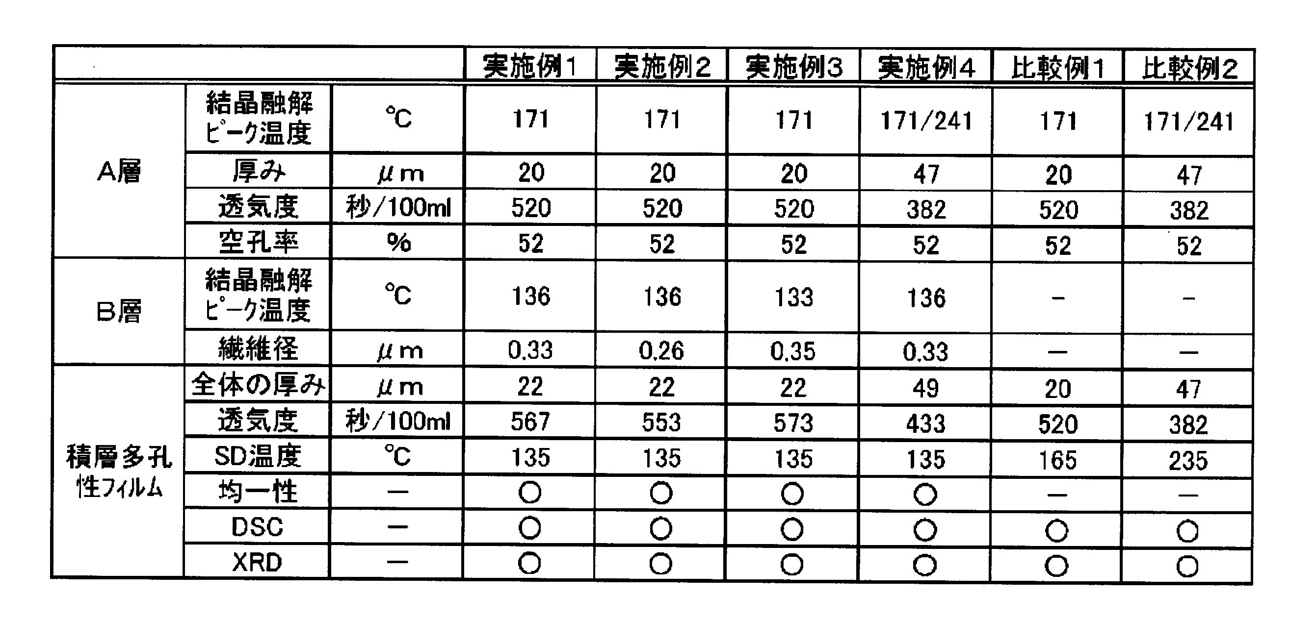
20 非水電解液電池
21 正極板
22 負極板
24 正極リード体
25 負極リード体
26 ガスケット
27 正極蓋
31 アルミ板
32 フィルム
33 クリップ
34 フィルム縦方向
35 フィルム横方向
Claims (9)
- 結晶融解ピーク温度が150℃以上250℃以下である熱可塑性樹脂組成物(a)を主成分とし、厚みが10μm以上である多孔膜層(A層)と、結晶融解ピーク温度が100℃以上150℃未満である熱可塑性樹脂組成物(b)を主成分とし、繊維径が1μm以下である不織布層(B層)とを有し、透気度が10~10000秒/100mlであることを特徴とする積層多孔性フィルム。
- 前記熱可塑性樹脂組成物(b)が、ポリエチレン系樹脂であることを特徴とする請求項1に記載の積層多孔性フィルム。
- 前記熱可塑性樹脂組成物(a)が、ポリプロピレン系樹脂組成物であることを特徴とする請求項1または請求項2に記載の積層多孔性フィルム。
- β活性を有することを特徴とする請求項1乃至請求項3のいずれか1項に記載の積層多孔性フィルム。
- 前記熱可塑性樹脂組成物(a)にβ晶核剤が配合されていることを特徴とする請求項1乃至請求項4のいずれか1項に記載の積層多孔性フィルム。
- 前記不織布層(B層)の厚さは10μm未満、シャットダウン温度が100℃以上150℃以下である請求項1乃至請求項5のいずれか1項に記載の積層多孔性フィルム。
- 前記熱可塑性樹脂組成物(b)を溶媒に溶解させて高分子溶液とし、当該高分子溶液に電圧を印加して紡糸させることで不織布を作成する方法(電界紡糸法)により、前記多孔膜層(A層)上に前記不織布層(B層)を形成させることを特徴とする請求項1乃至請求項6のいずれか1項に記載の積層多孔性フィルムの製造方法。
- 請求項1乃至請求項7のいずれか1項に記載の積層多孔性フィルムを用いてなる電池用セパレータ。
- 請求項8に記載の電池用セパレータを組み込んでなる電池。
Priority Applications (5)
| Application Number | Priority Date | Filing Date | Title |
|---|---|---|---|
| JP2012536545A JP5658758B2 (ja) | 2010-10-01 | 2011-09-29 | 積層多孔性フィルム、電池用セパレータ及び電池 |
| EP11829271.3A EP2623309A4 (en) | 2010-10-01 | 2011-09-29 | LAMINATED POROUS FILM, SEPARATOR FOR ONE BATTERY AND BATTERY |
| CN2011800465427A CN103124634A (zh) | 2010-10-01 | 2011-09-29 | 叠层多孔膜、电池用隔板及电池 |
| US13/876,729 US20130196208A1 (en) | 2010-10-01 | 2011-09-29 | Laminated porous film, separator for battery, and battery |
| KR1020137005463A KR101510972B1 (ko) | 2010-10-01 | 2011-09-29 | 적층 다공성 필름, 전지용 세퍼레이터 및 전지 |
Applications Claiming Priority (2)
| Application Number | Priority Date | Filing Date | Title |
|---|---|---|---|
| JP2010223764 | 2010-10-01 | ||
| JP2010-223764 | 2010-10-01 |
Publications (1)
| Publication Number | Publication Date |
|---|---|
| WO2012043718A1 true WO2012043718A1 (ja) | 2012-04-05 |
Family
ID=45893157
Family Applications (1)
| Application Number | Title | Priority Date | Filing Date |
|---|---|---|---|
| PCT/JP2011/072367 Ceased WO2012043718A1 (ja) | 2010-10-01 | 2011-09-29 | 積層多孔性フィルム、電池用セパレータ及び電池 |
Country Status (6)
| Country | Link |
|---|---|
| US (1) | US20130196208A1 (ja) |
| EP (1) | EP2623309A4 (ja) |
| JP (1) | JP5658758B2 (ja) |
| KR (1) | KR101510972B1 (ja) |
| CN (1) | CN103124634A (ja) |
| WO (1) | WO2012043718A1 (ja) |
Cited By (6)
| Publication number | Priority date | Publication date | Assignee | Title |
|---|---|---|---|---|
| WO2014100213A2 (en) | 2012-12-18 | 2014-06-26 | Sabic Innovative Plastics Ip B.V. | High temperature melt integrity battery separators via spinning |
| JPWO2021153792A1 (ja) * | 2020-01-31 | 2021-08-05 | ||
| JP2021122019A (ja) * | 2015-08-17 | 2021-08-26 | セルガード エルエルシー | 改良されたバッテリーセパレータおよび関連する方法 |
| JP2022051520A (ja) * | 2020-09-18 | 2022-03-31 | 旭化成株式会社 | 蓄電デバイス用セパレータ及び蓄電デバイス |
| JP2022051521A (ja) * | 2020-09-18 | 2022-03-31 | 旭化成株式会社 | 蓄電デバイス用セパレータ |
| JP2025528455A (ja) * | 2023-02-21 | 2025-08-28 | 香港時代新能源科技有限公司 | セパレータ、その製造方法及びそれに関連する二次電池ならびに電力消費装置 |
Families Citing this family (23)
| Publication number | Priority date | Publication date | Assignee | Title |
|---|---|---|---|---|
| US9455447B2 (en) | 2013-09-26 | 2016-09-27 | Eaglepicher Technologies, Llc | Lithium-sulfur battery and methods of preventing insoluble solid lithium-polysulfide deposition |
| US9882243B2 (en) | 2013-09-26 | 2018-01-30 | Eaglepicher Technologies, Llc | Lithium-sulfur battery and methods of reducing insoluble solid lithium-polysulfide depositions |
| US9991493B2 (en) | 2013-10-15 | 2018-06-05 | Eaglepicher Technologies, Llc | High energy density non-aqueous electrochemical cell with extended operating temperature window |
| JP6217974B2 (ja) * | 2013-12-11 | 2017-10-25 | トヨタ自動車株式会社 | 非水電解質二次電池 |
| US10680224B2 (en) | 2014-06-20 | 2020-06-09 | Toray Industries, Inc. | Polyolefin multilayer microporous film, method for producing same, and cell separator |
| US10270075B2 (en) * | 2015-07-09 | 2019-04-23 | E I Du Pont De Nemours And Company | Separator having adhesive layer, manufacturing method of the same, and electrochemical device having the same |
| JP6736375B2 (ja) | 2016-06-21 | 2020-08-05 | 住友化学株式会社 | 積層体 |
| JP7074419B2 (ja) | 2016-06-21 | 2022-05-24 | 住友化学株式会社 | 積層体 |
| JP6758943B2 (ja) | 2016-06-21 | 2020-09-23 | 住友化学株式会社 | 積層体 |
| JP6754628B2 (ja) | 2016-06-21 | 2020-09-16 | 住友化学株式会社 | 積層体 |
| JP6755726B2 (ja) | 2016-06-21 | 2020-09-16 | 住友化学株式会社 | 積層体 |
| JP6657029B2 (ja) | 2016-06-21 | 2020-03-04 | 住友化学株式会社 | 積層体 |
| JP6647973B2 (ja) | 2016-06-21 | 2020-02-14 | 住友化学株式会社 | 積層体 |
| JP2018181650A (ja) * | 2017-04-14 | 2018-11-15 | 住友化学株式会社 | 非水電解液二次電池用絶縁性多孔質層 |
| US11094997B2 (en) | 2017-05-29 | 2021-08-17 | Sumitomo Chemical Company, Limited | Nonaqueous electrolyte secondary battery |
| JP6430623B1 (ja) | 2017-12-19 | 2018-11-28 | 住友化学株式会社 | 非水電解液二次電池 |
| US11205799B2 (en) | 2017-12-19 | 2021-12-21 | Sumitomo Chemical Company, Limited | Nonaqueous electrolyte secondary battery |
| JP6430621B1 (ja) | 2017-12-19 | 2018-11-28 | 住友化学株式会社 | 非水電解液二次電池 |
| US11158907B2 (en) | 2017-12-19 | 2021-10-26 | Sumitomo Chemical Company, Limited | Nonaqueous electrolyte secondary battery |
| JP6430617B1 (ja) | 2017-12-19 | 2018-11-28 | 住友化学株式会社 | 非水電解液二次電池 |
| JP6430618B1 (ja) | 2017-12-19 | 2018-11-28 | 住友化学株式会社 | 非水電解液二次電池 |
| CN108172746A (zh) * | 2017-12-28 | 2018-06-15 | 成都市银隆新能源有限公司 | 一种锂电池隔膜 |
| CN115885359A (zh) * | 2020-09-18 | 2023-03-31 | 旭化成株式会社 | 蓄电设备用分隔件和蓄电设备 |
Citations (3)
| Publication number | Priority date | Publication date | Assignee | Title |
|---|---|---|---|---|
| JP2002170540A (ja) * | 2000-11-30 | 2002-06-14 | Tonen Tapyrus Co Ltd | セパレータ |
| JP2005019026A (ja) * | 2003-06-23 | 2005-01-20 | Japan Vilene Co Ltd | リチウム二次電池用セパレータ及びリチウム二次電池 |
| JP2008311220A (ja) * | 2007-05-11 | 2008-12-25 | Mitsubishi Plastics Inc | 積層多孔性フィルム、電池用セパレータおよび電池 |
Family Cites Families (9)
| Publication number | Priority date | Publication date | Assignee | Title |
|---|---|---|---|---|
| US5922492A (en) * | 1996-06-04 | 1999-07-13 | Tonen Chemical Corporation | Microporous polyolefin battery separator |
| US6730439B2 (en) * | 2000-08-01 | 2004-05-04 | Tonen Tapyrus Co., Ltd. | Heat-resistant separator |
| JP2002343327A (ja) * | 2001-05-11 | 2002-11-29 | Sony Corp | 電池用セパレータ |
| CA2772028C (en) * | 2004-04-22 | 2013-05-28 | Toray Industries, Inc. | Microporous polypropylene film and manufacturing method for same |
| CN101031421B (zh) * | 2004-10-01 | 2011-07-27 | 旭化成电子材料株式会社 | 聚烯烃微孔膜 |
| US10003058B2 (en) * | 2006-11-17 | 2018-06-19 | Celgard, Llc | Method of making a co-extruded, multi-layered battery separator |
| JP4299365B2 (ja) * | 2007-05-07 | 2009-07-22 | 三菱樹脂株式会社 | 積層多孔性フィルム及び電池用セパレータ |
| EP2337114B1 (en) * | 2008-09-03 | 2016-11-02 | Mitsubishi Plastics, Inc. | Laminated porous film for separator |
| JP5189459B2 (ja) * | 2008-10-27 | 2013-04-24 | 株式会社クラレ | リチウム電池用セパレータ及びそれを用いたリチウム電池 |
-
2011
- 2011-09-29 EP EP11829271.3A patent/EP2623309A4/en not_active Withdrawn
- 2011-09-29 WO PCT/JP2011/072367 patent/WO2012043718A1/ja not_active Ceased
- 2011-09-29 US US13/876,729 patent/US20130196208A1/en not_active Abandoned
- 2011-09-29 CN CN2011800465427A patent/CN103124634A/zh active Pending
- 2011-09-29 KR KR1020137005463A patent/KR101510972B1/ko not_active Expired - Fee Related
- 2011-09-29 JP JP2012536545A patent/JP5658758B2/ja not_active Expired - Fee Related
Patent Citations (3)
| Publication number | Priority date | Publication date | Assignee | Title |
|---|---|---|---|---|
| JP2002170540A (ja) * | 2000-11-30 | 2002-06-14 | Tonen Tapyrus Co Ltd | セパレータ |
| JP2005019026A (ja) * | 2003-06-23 | 2005-01-20 | Japan Vilene Co Ltd | リチウム二次電池用セパレータ及びリチウム二次電池 |
| JP2008311220A (ja) * | 2007-05-11 | 2008-12-25 | Mitsubishi Plastics Inc | 積層多孔性フィルム、電池用セパレータおよび電池 |
Non-Patent Citations (1)
| Title |
|---|
| See also references of EP2623309A4 * |
Cited By (14)
| Publication number | Priority date | Publication date | Assignee | Title |
|---|---|---|---|---|
| US9577235B2 (en) | 2012-12-18 | 2017-02-21 | Sabic Global Technologies B.V. | High temperature melt integrity battery separators via spinning |
| US10243187B2 (en) | 2012-12-18 | 2019-03-26 | Sabic Global Technologies B.V. | Process of making battery separators via spinning |
| WO2014100213A2 (en) | 2012-12-18 | 2014-06-26 | Sabic Innovative Plastics Ip B.V. | High temperature melt integrity battery separators via spinning |
| JP2021122019A (ja) * | 2015-08-17 | 2021-08-26 | セルガード エルエルシー | 改良されたバッテリーセパレータおよび関連する方法 |
| CN115023460B (zh) * | 2020-01-31 | 2024-04-05 | 旭化成株式会社 | 微多孔膜及其制造方法 |
| CN115023460A (zh) * | 2020-01-31 | 2022-09-06 | 旭化成株式会社 | 微多孔膜及其制造方法 |
| JP7437421B2 (ja) | 2020-01-31 | 2024-02-22 | 旭化成株式会社 | 微多孔膜及びその製造方法 |
| JPWO2021153792A1 (ja) * | 2020-01-31 | 2021-08-05 | ||
| US12370772B2 (en) | 2020-01-31 | 2025-07-29 | Asahi Kasei Battery Separator Corporation | Microporous film, and method for producing same |
| JP2022051520A (ja) * | 2020-09-18 | 2022-03-31 | 旭化成株式会社 | 蓄電デバイス用セパレータ及び蓄電デバイス |
| JP2022051521A (ja) * | 2020-09-18 | 2022-03-31 | 旭化成株式会社 | 蓄電デバイス用セパレータ |
| JP7822142B2 (ja) | 2020-09-18 | 2026-03-02 | 旭化成株式会社 | 蓄電デバイス用セパレータ及び蓄電デバイス |
| JP7822143B2 (ja) | 2020-09-18 | 2026-03-02 | 旭化成株式会社 | 蓄電デバイス用セパレータ |
| JP2025528455A (ja) * | 2023-02-21 | 2025-08-28 | 香港時代新能源科技有限公司 | セパレータ、その製造方法及びそれに関連する二次電池ならびに電力消費装置 |
Also Published As
| Publication number | Publication date |
|---|---|
| EP2623309A1 (en) | 2013-08-07 |
| JP5658758B2 (ja) | 2015-01-28 |
| US20130196208A1 (en) | 2013-08-01 |
| KR20130042595A (ko) | 2013-04-26 |
| CN103124634A (zh) | 2013-05-29 |
| JPWO2012043718A1 (ja) | 2014-02-24 |
| EP2623309A4 (en) | 2015-01-28 |
| KR101510972B1 (ko) | 2015-04-10 |
Similar Documents
| Publication | Publication Date | Title |
|---|---|---|
| JP5658758B2 (ja) | 積層多孔性フィルム、電池用セパレータ及び電池 | |
| JP5685039B2 (ja) | 積層多孔フィルム、非水電解液二次電池用セパレータ、および非水電解液二次電池 | |
| JP4299365B2 (ja) | 積層多孔性フィルム及び電池用セパレータ | |
| JP5507766B2 (ja) | 積層多孔フィルムの製造方法 | |
| JP5344107B1 (ja) | 積層多孔フィルム、非水電解液二次電池用セパレータ、及び非水電解液二次電池 | |
| JP5930032B2 (ja) | 積層多孔フィルム、非水電解液二次電池用セパレータ、及び非水電解液二次電池 | |
| JP5699212B2 (ja) | 多孔性フィルム、電池用セパレータ、および電池 | |
| JP6154585B2 (ja) | 積層多孔性フィルム | |
| JP6222087B2 (ja) | ポリオレフィン系樹脂多孔性フィルム | |
| JP6093636B2 (ja) | 積層多孔フィルム、非水電解液二次電池用セパレータ、及び非水電解液二次電池 | |
| JP2012092302A (ja) | 多孔性フィルム、電池用セパレータ及び電池 | |
| JP6103921B2 (ja) | 積層多孔性フィルム、電池用セパレータ、および電池 | |
| JP6117493B2 (ja) | 積層多孔フィルム、非水電解液二次電池用セパレータ、及び非水電解液二次電池 | |
| JP6137523B2 (ja) | 積層多孔フィルムの製造方法、積層多孔フィルム、非水電解液二次電池用セパレータ、及び非水電解液二次電池 | |
| JP2016013623A (ja) | 積層多孔フィルム、積層多孔フィルムの製造方法、非水電解液二次電池用セパレータ、及び非水電解液二次電池 | |
| JP5848193B2 (ja) | 積層多孔フィルム、非水電解液二次電池用セパレータ、及び非水電解液二次電池 | |
| JP5750511B2 (ja) | 電池用セパレータおよび電池 | |
| JP5460024B2 (ja) | 多孔性フィルム、それを利用したリチウム電池用セパレータ、および電池 | |
| JP6232771B2 (ja) | 多孔性フィルム、それを利用した電池用セパレータおよび電池 | |
| US20230335860A1 (en) | Separator for electric storage device and electric storage device |
Legal Events
| Date | Code | Title | Description |
|---|---|---|---|
| WWE | Wipo information: entry into national phase |
Ref document number: 201180046542.7 Country of ref document: CN |
|
| 121 | Ep: the epo has been informed by wipo that ep was designated in this application |
Ref document number: 11829271 Country of ref document: EP Kind code of ref document: A1 |
|
| WWE | Wipo information: entry into national phase |
Ref document number: 2012536545 Country of ref document: JP |
|
| ENP | Entry into the national phase |
Ref document number: 20137005463 Country of ref document: KR Kind code of ref document: A |
|
| WWE | Wipo information: entry into national phase |
Ref document number: 2011829271 Country of ref document: EP |
|
| WWE | Wipo information: entry into national phase |
Ref document number: 13876729 Country of ref document: US |
|
| NENP | Non-entry into the national phase |
Ref country code: DE |