WO2012043723A1 - Dispositif d'alimentation électrique - Google Patents
Dispositif d'alimentation électrique Download PDFInfo
- Publication number
- WO2012043723A1 WO2012043723A1 PCT/JP2011/072384 JP2011072384W WO2012043723A1 WO 2012043723 A1 WO2012043723 A1 WO 2012043723A1 JP 2011072384 W JP2011072384 W JP 2011072384W WO 2012043723 A1 WO2012043723 A1 WO 2012043723A1
- Authority
- WO
- WIPO (PCT)
- Prior art keywords
- battery
- storage battery
- voltage
- power supply
- parallel line
- Prior art date
- Legal status (The legal status is an assumption and is not a legal conclusion. Google has not performed a legal analysis and makes no representation as to the accuracy of the status listed.)
- Ceased
Links
Images

Classifications
-
- H—ELECTRICITY
- H02—GENERATION; CONVERSION OR DISTRIBUTION OF ELECTRIC POWER
- H02J—ELECTRIC POWER NETWORKS; CIRCUIT ARRANGEMENTS OR SYSTEMS FOR SUPPLYING OR DISTRIBUTING ELECTRIC POWER; SYSTEMS FOR STORING ELECTRIC ENERGY
- H02J7/00—Circuit arrangements for charging or discharging batteries or for supplying loads from batteries
- H02J7/50—Circuit arrangements for charging or discharging batteries or for supplying loads from batteries acting upon multiple batteries simultaneously or sequentially
- H02J7/52—Circuit arrangements for charging or discharging batteries or for supplying loads from batteries acting upon multiple batteries simultaneously or sequentially for charge balancing, e.g. equalisation of charge between batteries
- H02J7/56—Active balancing, e.g. using capacitor-based, inductor-based or DC-DC converters
-
- H—ELECTRICITY
- H01—ELECTRIC ELEMENTS
- H01M—PROCESSES OR MEANS, e.g. BATTERIES, FOR THE DIRECT CONVERSION OF CHEMICAL ENERGY INTO ELECTRICAL ENERGY
- H01M10/00—Secondary cells; Manufacture thereof
- H01M10/42—Methods or arrangements for servicing or maintenance of secondary cells or secondary half-cells
- H01M10/44—Methods for charging or discharging
- H01M10/441—Methods for charging or discharging for several batteries or cells simultaneously or sequentially
-
- H—ELECTRICITY
- H02—GENERATION; CONVERSION OR DISTRIBUTION OF ELECTRIC POWER
- H02J—ELECTRIC POWER NETWORKS; CIRCUIT ARRANGEMENTS OR SYSTEMS FOR SUPPLYING OR DISTRIBUTING ELECTRIC POWER; SYSTEMS FOR STORING ELECTRIC ENERGY
- H02J3/00—Circuit arrangements for AC mains or AC distribution networks
- H02J3/28—Arrangements for balancing of the load in networks by storage of energy
- H02J3/32—Arrangements for balancing of the load in networks by storage of energy using batteries or super capacitors with converting means
- H02J3/322—Arrangements for balancing of the load in networks by storage of energy using batteries or super capacitors with converting means the battery being on-board an electric or hybrid vehicle, e.g. vehicle to grid arrangements [V2G], power aggregation, use of the battery for network load balancing, coordinated or cooperative battery charging
-
- Y—GENERAL TAGGING OF NEW TECHNOLOGICAL DEVELOPMENTS; GENERAL TAGGING OF CROSS-SECTIONAL TECHNOLOGIES SPANNING OVER SEVERAL SECTIONS OF THE IPC; TECHNICAL SUBJECTS COVERED BY FORMER USPC CROSS-REFERENCE ART COLLECTIONS [XRACs] AND DIGESTS
- Y02—TECHNOLOGIES OR APPLICATIONS FOR MITIGATION OR ADAPTATION AGAINST CLIMATE CHANGE
- Y02E—REDUCTION OF GREENHOUSE GAS [GHG] EMISSIONS, RELATED TO ENERGY GENERATION, TRANSMISSION OR DISTRIBUTION
- Y02E60/00—Enabling technologies; Technologies with a potential or indirect contribution to GHG emissions mitigation
- Y02E60/10—Energy storage using batteries
Definitions
- the present invention relates to a power supply device that charges a battery unit with sunlight generated power or midnight power, and outputs the charged battery unit power as alternating current synchronized with a commercial power source, and in particular, a plurality of solar cells and commercial power sources. It is related with the power supply device which is stored in the battery unit of this and enlarges the output.
- a power supply system that stores and uses electric power generated using natural energy that does not depend on fossil fuels has been proposed (for example, see Patent Document 1).
- a solar battery and a secondary battery are connected via a switch element, and a control circuit controls ON / OFF of the switch element to perform charge control from the solar battery to the secondary battery.
- the electric power obtained by sunlight in the daytime can be stored in the secondary battery, and the secondary battery can be discharged when necessary to use the electric power.
- the secondary battery In such a power supply system, the secondary battery is not charged with electric power that can obtain a stable output like a normal commercial power supply, but is used with unstable electric power whose output largely fluctuates due to sunlight. I have to charge it. With solar cells, it is difficult to obtain stable power generation every day, and the electric power obtained varies depending on the weather, season, etc., and the change from day to day is particularly large. On the other hand, in order to use a secondary battery stably over a long period of time, according to conditions such as an appropriate current value and voltage value according to the type of secondary battery to be used, it is possible to avoid over-discharge and over-charge while It is important to charge and discharge within the range.
- Unstable power generated by solar cells can be eliminated by using midnight power.
- the secondary battery can be charged to a predetermined capacity by charging the secondary battery with late-night power on the day before when the sunshine time is short in the weather forecast.
- solar cells can effectively use natural energy, and late-night power can effectively use power output from a generator that cannot be stopped at night.
- a large-capacity storage battery is realized by connecting a large number of unit cells in series or in parallel.
- the output voltage can be increased by increasing the number of cells connected in series, and the output current can be increased by increasing the number of cells connected in parallel. Since this storage battery is composed of a large number of unit cells having different electrical characteristics and deteriorated characteristics, it can be effectively used as a structure in which a part can be replaced.
- a structure in which a battery unit is constituted by a plurality of unit cells and a plurality of battery units are connected in parallel to form a storage battery can be used even when some battery units are removed or increased. This is because the number of battery units connected in parallel does not change the output voltage of the storage battery. Therefore, the storage battery of this structure has the feature that the capacity can be increased by increasing the number of battery units connected in parallel, and the maintenance can be simplified by replacing the battery unit by removing or connecting it.
- a large inrush current may flow at the moment of connection. This is because the voltage of the battery unit to be connected is different from the voltage of the storage battery. When the voltage of the battery unit is lower than that of the storage battery, a large charging current flows from the storage battery to the battery unit. Conversely, when the voltage of the battery unit is higher than that of the storage battery, a discharge current flows from the battery unit.
- a large inrush current flowing at the time of connection not only adversely affects the cells constituting the battery unit, but also causes a failure of a switch that connects the battery unit to the storage battery. This problem can be solved by connecting the battery unit to the storage battery via a current limiting resistor.
- the current limiting resistor limits the inrush current to a current inversely proportional to the electrical resistance in proportion to the voltage difference between the battery unit and the storage battery. Therefore, the current limiting resistor can increase the electrical resistance and reduce the inrush current. However, the current limiting resistor generates heat due to Joule heat due to the inrush current, and the amount of generated heat increases in proportion to the electrical resistance. Therefore, if the electric resistance of the current limiting resistor is increased, the amount of heat generated by the current limiting resistor is increased until the voltage difference between the battery unit and the storage battery is eliminated, and this has the disadvantage of being heated. The heat generation of the current limiting resistor not only wastes power charged in the battery unit or the storage battery, but also makes it difficult to dissipate the current limiting resistor.
- the present invention has been made in view of such a conventional problem.
- the main object of this invention is to provide the power supply device which can make small the emitted-heat amount of a current limiting resistance, connecting the battery unit with a voltage difference to a storage battery.
- Another important object of the present invention is to charge the storage battery with a solar battery or midnight power, and to effectively use the charged power, and to increase the capacity of the storage battery while simplifying its maintenance. To provide an apparatus.
- the power supply device of the present invention connects a storage battery 1 formed by connecting a plurality of battery units 2 to a parallel line 10, a power supply 9 for charging the battery unit 2 constituting the storage battery 1, and connects the battery unit 2 to the parallel line 10.
- a pre-connection circuit 6 comprising a series circuit of a current limiting resistor 11 and an equalizing switch 12, a main switch 7 for connecting the battery unit 2 whose voltage difference has been eliminated by the pre-connection circuit 6 to the parallel line 10, and a pre-connection circuit 6 and a control circuit 8 for controlling the equalizing switch 12 and the main switch 7 on and off.
- the control circuit 8 is connected to the pre-connection circuit 6 while the voltage difference between the voltage of the parallel line 10 connected to the storage battery 1 and the voltage of the battery unit 2 connected to the parallel line 10 is smaller than the set voltage.
- the equalization switch 12 is switched on, the voltage of the battery unit 2 is equalized to the voltage of the parallel line 10, and the equalized battery unit 2 is switched on by the control circuit 8 via the main switch 7. 10 is connected.
- the above power supply device realizes the feature that the heat generation amount of the current limiting resistor that limits the inrush current and equalizes the voltage can be reduced when a battery unit having a voltage difference is replaced.
- a battery unit in which the voltage difference is equalized by detecting a state where the voltage difference is smaller than the set value in the storage battery whose voltage varies, and connecting the battery unit in parallel with the storage battery via the current limiting resistor. Is connected in parallel with the storage battery.
- the power source 9 includes a solar battery 3 that charges the battery unit 2 that constitutes the storage battery 1, and a charging circuit 4 that charges the battery unit 2 that constitutes the storage battery 1 with the commercial power source 30. Furthermore, the DC / AC inverter 5 which is connected to the parallel line 10 and converts the output of the storage battery 1 into alternating current synchronized with the commercial power supply 30 and outputs the alternating current can be provided.
- the above power supply device can effectively use natural energy and midnight power that is not wasted, and can simplify maintenance while increasing the capacity of the storage battery. There are features.
- the above power supply device is connected to a battery that is charged with a solar battery or midnight power, discharged in the daytime, and the voltage fluctuates every day while detecting a state where the voltage difference is smaller than a set value.
- the amount of heat generated by the current limiting resistor can be reduced.
- the charging circuit 4 includes a timer 16 for storing the charging time of the storage battery 1, and the storage battery 1 can be charged by the commercial power supply 30 in the time zone stored in the timer 16.
- the above power supply device can charge the storage battery by effectively using the midnight power at which the electricity bill is reduced by storing the time zone of the midnight power in the timer.
- the battery unit 2 can connect a plurality of unit cells 21 in series and in parallel.
- the battery unit includes a plurality of unit cells connected in series and in parallel, so that the output voltage and output current of the battery unit can be increased.
- each element constituting the present invention may be configured such that a plurality of elements are constituted by the same member and the plurality of elements are shared by one member, and conversely, the function of one member is constituted by a plurality of members. It can also be realized by sharing.
- the contents described in some examples and embodiments may be used in other examples and embodiments.
- the power supply device shown in FIG. 1 charges the storage battery 1 with a power supply 9 and supplies power to the load 40 from the charged storage battery 1.
- the power supply device of FIG. 1 charges the storage battery 1 with the solar battery 3 as the power supply 9 and the commercial power supply 30 and outputs the charged storage battery 1 to the load 40 of the commercial power supply 30 via the DC / AC inverter 5.
- the load 40 is supplied with power from both the commercial power supply 30 and the storage battery 1. Therefore, the DC / AC inverter 5 that converts the output of the storage battery 1 into alternating current outputs alternating current synchronized with the alternating current of the commercial power supply 30.
- the DC / AC inverter 5 supplies power to the load 40 while controlling the power output from the storage battery 1.
- the power supply device is installed, for example, in a bicycle parking lot and charges the battery of the electric bicycle.
- the power supply device used for this application outputs alternating current synchronized with the commercial power supply from the DC / AC inverter.
- this power supply device is provided with a charger as a load that converts the voltage and current to charge the battery of the electric bicycle with an AC commercial power supply.
- the charger converts both the power output from the DC / AC inverter and the power of the commercial power source into a voltage and a current for charging the battery, and outputs the converted voltage and current.
- the charger charges the battery only with the output of the DC / AC inverter.
- the charger charges the battery with the output of both the DC / AC inverter and the commercial power supply. Further, when the storage battery is completely discharged and the discharge is stopped, the charger charges the battery with only the commercial power source.
- the DC / AC inverter detects the remaining capacity of the storage battery and controls the output. When the remaining capacity of the storage battery becomes smaller than the set value, the DC / AC inverter stops operating and stops discharging the storage battery.
- the power supply device is also used for supplying power together with a commercial power supply to a load that instantaneously consumes a large amount of power.
- a commercial power supply For example, when supplying heat to an air conditioner when it is hot in summer, or when multiple microwave ovens installed in restaurants such as convenience stores and canteens are used at the same time, power is supplied to the load air conditioner and microwave oven along with commercial power. Supply and limit the peak power consumed by the load from commercial power.
- the power plant is designed to withstand the maximum output at which the power consumption reaches a peak value. The power consumption of the power plant reaches its peak value during the hottest daytime in summer, and occurs at the same time that many air conditioners are used.
- This method effectively uses midnight power to charge the storage battery, effectively uses midnight power, and further discharges it at the timing when the power consumption reaches its peak value, thereby reducing the peak power of the power plant.
- the power supply device of the present invention can also be used for this purpose.
- a plurality of microwave ovens are provided so that food can be heated.
- the microwave oven used in this state is used at a time during meals. For this reason, power consumption temporarily becomes extremely large.
- the power supply device of the present invention can be used for this purpose to reduce the peak power. This is because when a plurality of microwave ovens are used, not only the commercial power supply but also the storage battery can be discharged to supply power to the load microwave oven together with the commercial power supply.
- the power supply device used for the above applications includes a storage battery 1 that connects a plurality of battery units 2 to a parallel line 10, a power supply 9 that charges the battery unit 2 of the storage battery 1, A pre-connection circuit 6 for connecting the battery unit 2 having a voltage difference to the parallel line 10; a main switch 7 for connecting the battery unit 2 that has been equalized by eliminating the voltage difference in the pre-connection circuit 6; A control circuit 8 for controlling the equalization switch 12 and the main switch 7 of the pre-connection circuit 6 to be turned on / off is provided.
- the power supply apparatus shown in the figure includes a solar battery 3 and a charging circuit 4 that charges the battery unit 2 of the storage battery 1 with a commercial power supply 30 as a power supply 9 that charges the battery unit 2 of the battery 1. Furthermore, the power supply apparatus of the figure has connected to the parallel line 10 the DC / AC inverter 5 which converts the output of the storage battery 1 into the alternating current synchronized with the commercial power supply 30, and outputs it.
- the power supply device of FIG. 1 is provided with a charge switch 13 and a discharge switch 14 on the output side of the parallel line 10.
- the charge switch 13 connects the storage battery 1 to the output of the solar battery 3 and the charging circuit 4, and the discharge switch 14 connects the storage battery 1 to the DC / AC inverter 5.
- the charge switch 13 and the discharge switch 14 are controlled by the control circuit 8.
- the control circuit 8 detects the remaining capacity of the storage battery 1 and controls the charging switch 13 and the discharging switch 14 to be turned on and off.
- the control circuit 8 turns on the charging switch 13 to charge the storage battery 1, and when the storage battery 1 is fully charged, switches the charging switch 13 to off to stop charging.
- the discharge switch 14 is turned on to discharge the storage battery 1, and when the remaining capacity of the storage battery 1 reaches the minimum capacity, the discharge switch 14 is switched off to stop the discharge of the storage battery 1.
- the control circuit controls the DC / AC inverter instead of the discharge switch, and when the remaining capacity of the storage battery decreases to the minimum capacity, the control circuit can also stop the discharge of the storage battery by not operating the DC / AC inverter.
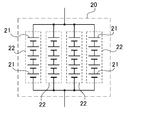
- the storage battery 1 includes a plurality of battery units 2, and each battery unit 2 connects a plurality of battery blocks 20 in series, and each battery block 20 connects unit cells in series and in parallel. .
- the battery block 20 preferably has unit cells connected in series and in parallel.
- the unit cell is a lithium ion battery. However, as the unit cell, any rechargeable battery such as a nickel metal hydride battery or a nickel cadmium battery can be used.
- the battery block 20 includes, for example, unit cells 21 made of five lithium ion batteries connected in series to form a series unit 22, and further four sets of series units 22 are connected in parallel.
- the battery block 20 can have an output voltage of about 20 V and a current capacity four times that of one lithium ion battery.
- unit cells made of 13 lithium ion batteries can be connected in series to form a series unit, and 24 series units can be connected in parallel.
- the capacity of one set of battery blocks 20 is 150 Wh, and five sets of battery blocks 20 are connected in series to form a battery unit 2, so that the capacity of the battery unit 2 can be 750 Wh.
- the capacity of the storage battery 1 can be considerably increased to 3.75 kW.
- the storage battery 1 can operate an air conditioner with a power consumption of 1 KW for 3.7 hours, and can simultaneously use five microwave ovens with a power consumption of 1 KW for about 45 minutes.
- the storage battery 1 can be further increased or decreased in capacity by changing the number of battery units 2 connected in parallel.
- the solar cell 3 is connected to the parallel line 10 and charges the storage battery 1 with generated power.
- the solar cell 3 is connected to the parallel line 10 via the charge switch 13 and the diode 15 to charge the storage battery 1 with an output voltage.
- the solar cell 3 charges the storage battery 1 in the daytime. When the storage battery 1 having a large remaining capacity is charged by the solar battery 3, it is overcharged. Overcharging causes the storage battery 1 to deteriorate. In order to prevent this adverse effect, the control circuit 8 detects the full charge of the storage battery 1 and switches the charging switch 13 off.
- the storage battery 1 is charged by both the solar battery 3 and the charging circuit 4.
- the charging circuit 4 charges the storage battery 1 in a state where the charging capacity is insufficient due to the charging of the solar battery 3. In a state where the solar battery 3 is sufficiently charged, the storage battery 1 is charged only by the solar battery 3 and is not charged by the charging circuit 4.
- the charging circuit 4 detects the remaining capacity of the storage battery 1 at the timing of charging the storage battery 1 with midnight power, and estimates the capacity that the solar battery 3 can charge the storage battery 1 and the capacity that the storage battery 1 is discharged the next day. And the capacity
- the capacity that the solar battery 3 charges the storage battery 1 on the next day is estimated from the weather forecast, and the capacity that the storage battery 1 is discharged on the next day is estimated from the average value of the past discharge capacity.
- the charging circuit 4 estimates the charging capacity of the storage battery 1 so that the power that can be supplied from the storage battery 1 to the load 40 is maximized by the solar battery 3 so that the storage battery 1 is not fully charged in the daytime. The storage battery 1 is charged. When the charging capacity of the solar battery 3 on the next day is low, the charging circuit 4 increases the charging capacity of the storage battery 1 and on the contrary, the charging capacity of the solar battery 3 on the next day is large. Reduces the charging capacity of the storage battery 1.
- the charging circuit 4 includes a timer 16 that specifies the time for charging the storage battery 1. The timer 16 is set in a time zone in which the storage battery 1 is charged with midnight power.
- the DC / AC inverter 5 converts the direct current output from the storage battery 1 into alternating current synchronized with the commercial power supply 30 and supplies it to the load 40.
- the maximum output of the DC / AC inverter 5 is limited to the maximum value of the discharge current of the storage battery 1.
- the DC / AC inverter 5 outputs an alternating current smaller than the maximum output.
- the AC load 40 is supplied with power from both the output from the DC / AC inverter 5 and the commercial power supply 30. In a state where the power consumption of the load 40 is smaller than the output of the DC / AC inverter 5, power is supplied to the load 40 only from the DC / AC inverter 5.
- the pre-connection circuit 6 is composed of a series circuit of a current limiting resistor 11 and an equalizing switch 12.
- the current limiting resistor 11 equalizes the voltage of the battery unit 2 while limiting the excessive current flowing through the battery unit 2 connected to the parallel line 10 to a small value.
- the power supply device of the present invention in which the capacity of the storage battery 1 is increased by connecting a plurality of battery units 2 in parallel is different when the battery unit 2 is replaced or when the number of battery units 2 is increased. It is necessary to connect the battery unit 2 to the parallel line 10. At this time, the voltage of the newly connected battery unit 2 is not necessarily the same as the voltage of the parallel line 10.
- the voltage difference between the battery unit 2 and the voltage of the parallel line 10 has a harmful effect of flowing an excessive current to the battery unit 2 to be connected.
- the current limiting resistor 11 limits this current.
- the current limiting resistor 11 can increase the electric resistance and reduce the current of the battery unit 2 having a voltage difference. However, if the electric resistance of the current limiting resistor 11 is increased, the amount of heat generated by Joule heat increases, and the time for equalizing the voltage of the battery unit 2 becomes longer. Therefore, the electric resistance of the current limiting resistor 11 is set to an electric resistance that can reduce the amount of heat generation while quickly equalizing the voltage of the battery unit 2.
- the optimum value of the electric resistance of the current limiting resistor 11 varies depending on the voltage of the battery unit 2, but the voltage of the battery unit 2 is set to 20 V, for example, 1 ⁇ to 5 ⁇ , preferably 1 ⁇ to 3 ⁇ , more preferably 1 ⁇ to 2 ⁇ .
- the equalization switch 12 is a relay. However, the equalization switch may be a semiconductor switching element such as an FET or a transistor.
- the main switch 7 is a switch for connecting the battery unit 2 with the equalized voltage to the parallel line 10, and is a relay or a semiconductor switching element.
- the main switch 7 is controlled by the control circuit 8 to connect the battery units 2 equalized by the pre-connection circuit 6 to the parallel line 10.
- the control circuit 8 controls the equalization switch 12 of the pre-connection circuit 6 by comparing the voltage of the battery unit 2 connected to the parallel line 10 with the voltage of the parallel line 10. Further, the control circuit 8 detects the equalization of the battery unit 2 and controls the main switch 7.
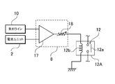
- the control circuit 8 shown in FIG. 3 includes a differential amplifier 17 that connects the voltage of the parallel line 10 and the voltage of the battery unit 2 to the input side in order to switch the equalization switch 12 on and off.
- the relay 12A is connected to the output side of the differential amplifier 17, and the normally-on contact 12a of the relay 12A is used as the equalizing switch 12.
- the normally-on contact 12a is turned on when the excitation coil 12b of the relay 12A is not energized and turned off when the excitation coil 12b is energized.
- the relay 12A is switched on / off by the output of the differential amplifier 17.
- a series resistor 18 is connected between the output side of the differential amplifier 17 and the exciting coil 12b of the relay 12A.
- the series resistor 18 adjusts the output voltage for switching the relay 12A on and off by the output of the differential amplifier 17.
- the differential amplifier 17 can adjust the voltage amplification factor by the negative feedback amount and adjust the voltage difference between the battery unit 2 that switches the equalization switch 12 on and the parallel line 10 to an optimum value.
- the above control circuit 8 removes and replaces or maintains the battery unit 2 for reasons of abnormality, failure, characteristic deterioration, or for maintenance reasons, etc., and attaches the battery unit 2 so that the battery unit 2 is connected to the parallel line 10.
- the control circuit 8 is in a state where the voltage difference between the voltage of the battery unit 2 and the parallel line 10 is large, the output voltage of the relay 12A is large, the excitation coil 12b of the relay 12A is excited, The contact 12a is kept off.
- the battery unit 2 When the voltage of the battery unit 2 approaches the parallel line 10 and the output voltage of the differential amplifier 17 decreases, the current flowing through the exciting coil 12b of the relay 12A decreases, the relay 12A is switched, and the equalization switch 12 A certain normally-on contact 12a is switched from off to on. In this state, the battery unit 2 is connected to the parallel line 10 via the current limiting resistor 11 and the equalizing switch 12, and the voltage is equalized.
- a control circuit for switching on and off a semiconductor switching element such as an FET is equivalent to an A / D converter that converts a voltage of a battery unit and a voltage of a parallel line into a digital signal at a constant sampling period, and an output of the A / D converter.
- the control circuit compares the voltage of the battery unit input as a digital signal with a constant period and the voltage of the parallel line, and the voltage difference is a set value (for example, five battery blocks in which 13 batteries are connected in series). When the voltage is greater than 5 V when connected in series, the equalization switch is kept off, and when the voltage difference becomes smaller than the set value, the equalization switch is turned on.
- This control circuit stores a voltage value for turning on the equalization switch as a set value. Then, the voltage of the battery unit is compared with the voltage of the parallel line, and the voltage difference is a second set value (for example, about 5 V when five battery blocks 20 in which 13 batteries are connected in series are connected in series). And the equalization switch is turned off and the main switch is switched from off to on.
- control circuit 8 detects that the battery unit 2 has been equalized, switches the main switch 7 on, and connects the battery unit 2 to the parallel line 10.
- control circuit 8 includes a timer 19.
- the timer 19 stores a time up time as a set time. The timer 19 starts counting at the timing when the equalization switch 12 is turned on. When the set time elapses, the timer 19 is timed up and the main switch 7 is turned on.
- the control circuit can detect that the current flowing through the current limiting resistor is smaller than the set value regardless of the timer, and can turn on the main switch.
- This control circuit keeps the main switch off when no current flows through the current limiting resistor, that is, when the equalization switch is off, and the current flows through the current limiting resistor, which is smaller than the set value. And the main switch is turned on.
- This control circuit detects the current of the current limiting resistor at a constant sampling period, detects that the detected current value is smaller than the set value, and turns on the main switch.
- the power supply device effectively uses the generated power or late-night power of a solar battery stored in a storage battery to supply electric power to a temporary large load such as a battery of an electric bicycle, an air conditioner or a microwave oven.
- a temporary large load such as a battery of an electric bicycle, an air conditioner or a microwave oven.
- the peak power of the power plant can be reduced.
Landscapes
- Engineering & Computer Science (AREA)
- Power Engineering (AREA)
- Manufacturing & Machinery (AREA)
- Chemical & Material Sciences (AREA)
- Chemical Kinetics & Catalysis (AREA)
- Electrochemistry (AREA)
- General Chemical & Material Sciences (AREA)
- Charge And Discharge Circuits For Batteries Or The Like (AREA)
- Secondary Cells (AREA)
- Battery Mounting, Suspending (AREA)
Abstract
L'invention concerne la possibilité de réduire la quantité de chaleur générée dans une résistance de limitation de courant tout en connectant des unités de batterie ayant des différences de tension différentes à une batterie d'accumulateurs. L'invention concerne donc un dispositif d'alimentation électrique qui comporte : une batterie d'accumulateurs (1) qui est équipée de multiples unités de batterie (2) ; une alimentation électrique (9) qui charge les unités de batterie (2) ; un circuit de connexion préalable (6) qui comporte un circuit série composé d'une résistance de limitation de courant (11) afin de connecter les unités de batterie (2) à une ligne parallèle (10) et un interrupteur d'égalisation (12) ; un interrupteur principal (7) qui connecte les unités de batterie (2) à la ligne parallèle (10), et un circuit de commande (8) qui commande l'interrupteur d'égalisation (12) et l'interrupteur principal (7). Dans le dispositif d'alimentation électrique, l'interrupteur d'égalisation (12) est « débloqué » dans un état tel que la différence entre la tension de la ligne parallèle (10) et la tension de chacune des unités de batterie (2) devient inférieure à une tension réglée, égalisant ainsi la tension de chacune des unités de batterie (2) à la tension de la ligne parallèle (10). Les unités de batterie égalisées (2) sont connectées à la ligne parallèle (10) par l'interrupteur principal (7).
Priority Applications (1)
| Application Number | Priority Date | Filing Date | Title |
|---|---|---|---|
| JP2012536547A JPWO2012043723A1 (ja) | 2010-10-01 | 2011-09-29 | 電源装置 |
Applications Claiming Priority (2)
| Application Number | Priority Date | Filing Date | Title |
|---|---|---|---|
| JP2010-223793 | 2010-10-01 | ||
| JP2010223793 | 2010-10-01 |
Publications (1)
| Publication Number | Publication Date |
|---|---|
| WO2012043723A1 true WO2012043723A1 (fr) | 2012-04-05 |
Family
ID=45893161
Family Applications (1)
| Application Number | Title | Priority Date | Filing Date |
|---|---|---|---|
| PCT/JP2011/072384 Ceased WO2012043723A1 (fr) | 2010-10-01 | 2011-09-29 | Dispositif d'alimentation électrique |
Country Status (2)
| Country | Link |
|---|---|
| JP (1) | JPWO2012043723A1 (fr) |
| WO (1) | WO2012043723A1 (fr) |
Cited By (25)
| Publication number | Priority date | Publication date | Assignee | Title |
|---|---|---|---|---|
| WO2013008859A1 (fr) * | 2011-07-12 | 2013-01-17 | 三洋電機株式会社 | Système de commande d'ensemble d'accumulateurs |
| WO2013018693A1 (fr) * | 2011-07-29 | 2013-02-07 | 三洋電機株式会社 | Système de commande de charge/décharge pour un ensemble d'éléments de stockage |
| US20130264873A1 (en) * | 2011-03-29 | 2013-10-10 | Ichirou Katou | Power supply control system |
| JP2013240142A (ja) * | 2012-05-11 | 2013-11-28 | Toyota Industries Corp | 組電池の接続方法および組電池 |
| EP2670012A1 (fr) * | 2012-05-16 | 2013-12-04 | LG Electronics, Inc. | Dispositif de stockage d'énergie et procédé de commande de celui-ci |
| JP2014007913A (ja) * | 2012-06-27 | 2014-01-16 | Iks Co Ltd | 電圧給電蓄電制御システム |
| WO2014033880A1 (fr) * | 2012-08-30 | 2014-03-06 | 株式会社安川電機 | Dispositif de stockage d'énergie |
| WO2014156041A1 (fr) * | 2013-03-29 | 2014-10-02 | 三洋電機株式会社 | Système d'alimentation électrique et procédé de commande de charge et décharge pour système d'alimentation électrique |
| AT514419A1 (de) * | 2013-05-28 | 2014-12-15 | Kosolar Pv Gmbh | Verfahren zur direkten Speicherung von Energie aus Energieerzeugungsanlagen in elektrochemischen Energiespeichern |
| WO2014207994A1 (fr) * | 2013-06-28 | 2014-12-31 | ソニー株式会社 | Système d'accumulation d'électricité, module d'accumulation d'électricité, et procédé de commande |
| CN104810902A (zh) * | 2014-12-30 | 2015-07-29 | 北京新能源汽车股份有限公司 | 移动充电装置和方法 |
| CN105075056A (zh) * | 2013-03-28 | 2015-11-18 | 索尼公司 | 蓄电装置、蓄电系统、以及蓄电装置的控制方法 |
| JP2016170938A (ja) * | 2015-03-12 | 2016-09-23 | プライムアースEvエナジー株式会社 | 電池システムの電池パック交換方法及び電池パック |
| JP2017168244A (ja) * | 2016-03-15 | 2017-09-21 | プライムアースEvエナジー株式会社 | 電池システムの電池パック交換方法及び電池パック |
| CN107750413A (zh) * | 2015-11-18 | 2018-03-02 | 艾达司股份有限公司 | 控制装置、蓄电装置及蓄电系统 |
| US9917461B2 (en) | 2013-11-19 | 2018-03-13 | Eliiy Power Co., Ltd. | Battery unit, overcurrent control method, and computer program for the same |
| EP3309920A3 (fr) * | 2016-10-14 | 2018-05-30 | Contemporary Amperex Technology Co., Limited | Procédé de branchement à chaud, dispositif de commande pour branchement à chaud, procédé et dispositif d'équilibrage de tension |
| JP2020530255A (ja) * | 2017-08-10 | 2020-10-15 | ズークス インコーポレイテッド | スマートバッテリ回路 |
| CN112134334A (zh) * | 2020-10-23 | 2020-12-25 | 南京拓途电子有限公司 | 一种锂电池板并联充放电均衡方法及其实现电路 |
| DE102019211321A1 (de) * | 2019-07-30 | 2021-02-04 | Robert Bosch Gmbh | Elektrisches Energiespeichersystem und Verfahren zu dessen Betreiben |
| EP3809553A1 (fr) * | 2019-10-17 | 2021-04-21 | Samsung SDI Co., Ltd. | Système de batterie |
| CN112848969A (zh) * | 2019-11-27 | 2021-05-28 | 光阳工业股份有限公司 | 电动车辆的电池并联控制方法 |
| CN113767544A (zh) * | 2019-10-22 | 2021-12-07 | 株式会社Lg新能源 | 用于控制并联多电池组中包括的开关单元的接通操作的装置和方法 |
| CN114204647A (zh) * | 2022-01-06 | 2022-03-18 | 上海交通大学 | 并联电池簇状态管理系统及并联电池簇 |
| CN114709903A (zh) * | 2022-05-09 | 2022-07-05 | 蓝谷智慧(北京)能源科技有限公司 | 储能系统及其均衡控制方法、计算机存储介质 |
Families Citing this family (1)
| Publication number | Priority date | Publication date | Assignee | Title |
|---|---|---|---|---|
| JP7794145B2 (ja) * | 2023-02-23 | 2026-01-06 | 株式会社デンソー | 電池制御装置、電池制御プログラム及び電池制御方法 |
Citations (4)
| Publication number | Priority date | Publication date | Assignee | Title |
|---|---|---|---|---|
| JP2007259612A (ja) * | 2006-03-24 | 2007-10-04 | Hitachi Ltd | 電源制御装置 |
| JP2009212020A (ja) * | 2008-03-06 | 2009-09-17 | Toshiba Corp | 蓄電装置 |
| JP2009232668A (ja) * | 2007-10-17 | 2009-10-08 | Yasushi Tomiyama | 電力供給システムおよび電力供給方法 |
| JP2010045923A (ja) * | 2008-08-13 | 2010-02-25 | Mitsubishi Heavy Ind Ltd | 蓄電システム |
Family Cites Families (3)
| Publication number | Priority date | Publication date | Assignee | Title |
|---|---|---|---|---|
| JP2001136659A (ja) * | 1999-11-08 | 2001-05-18 | Auto Network Gijutsu Kenkyusho:Kk | 電流供給回路 |
| JP2004236473A (ja) * | 2003-01-31 | 2004-08-19 | Sanyo Electric Co Ltd | 二次電池装置 |
| JP3162937U (ja) * | 2010-07-09 | 2010-09-24 | 永興電機工業株式会社 | パワーユニット及びそれを用いたリフト装置 |
-
2011
- 2011-09-29 WO PCT/JP2011/072384 patent/WO2012043723A1/fr not_active Ceased
- 2011-09-29 JP JP2012536547A patent/JPWO2012043723A1/ja active Pending
Patent Citations (4)
| Publication number | Priority date | Publication date | Assignee | Title |
|---|---|---|---|---|
| JP2007259612A (ja) * | 2006-03-24 | 2007-10-04 | Hitachi Ltd | 電源制御装置 |
| JP2009232668A (ja) * | 2007-10-17 | 2009-10-08 | Yasushi Tomiyama | 電力供給システムおよび電力供給方法 |
| JP2009212020A (ja) * | 2008-03-06 | 2009-09-17 | Toshiba Corp | 蓄電装置 |
| JP2010045923A (ja) * | 2008-08-13 | 2010-02-25 | Mitsubishi Heavy Ind Ltd | 蓄電システム |
Cited By (52)
| Publication number | Priority date | Publication date | Assignee | Title |
|---|---|---|---|---|
| US20130264873A1 (en) * | 2011-03-29 | 2013-10-10 | Ichirou Katou | Power supply control system |
| US9263897B2 (en) * | 2011-03-29 | 2016-02-16 | Panasonic Intellectual Property Management Co., Ltd. | Power supply control system |
| JPWO2013008859A1 (ja) * | 2011-07-12 | 2015-02-23 | 三洋電機株式会社 | 蓄電池集合体制御システム |
| WO2013008859A1 (fr) * | 2011-07-12 | 2013-01-17 | 三洋電機株式会社 | Système de commande d'ensemble d'accumulateurs |
| WO2013018693A1 (fr) * | 2011-07-29 | 2013-02-07 | 三洋電機株式会社 | Système de commande de charge/décharge pour un ensemble d'éléments de stockage |
| JPWO2013018693A1 (ja) * | 2011-07-29 | 2015-03-05 | 三洋電機株式会社 | 蓄電池集合体の充放電制御システム |
| JP2013240142A (ja) * | 2012-05-11 | 2013-11-28 | Toyota Industries Corp | 組電池の接続方法および組電池 |
| EP2670012A1 (fr) * | 2012-05-16 | 2013-12-04 | LG Electronics, Inc. | Dispositif de stockage d'énergie et procédé de commande de celui-ci |
| US9413185B2 (en) | 2012-05-16 | 2016-08-09 | Lg Electronics Inc. | Energy storage device and method for controlling the same |
| JP2014007913A (ja) * | 2012-06-27 | 2014-01-16 | Iks Co Ltd | 電圧給電蓄電制御システム |
| CN104541433A (zh) * | 2012-08-30 | 2015-04-22 | 株式会社安川电机 | 蓄电装置 |
| WO2014033880A1 (fr) * | 2012-08-30 | 2014-03-06 | 株式会社安川電機 | Dispositif de stockage d'énergie |
| CN104541433B (zh) * | 2012-08-30 | 2017-05-31 | 株式会社安川电机 | 蓄电装置 |
| JPWO2014033880A1 (ja) * | 2012-08-30 | 2016-08-08 | 株式会社安川電機 | 蓄電装置 |
| EP2980954A4 (fr) * | 2013-03-28 | 2016-11-23 | Sony Corp | Dispositif de stockage de courant, système de stockage de courant et procédé de commande de dispositif de stockage de courant |
| CN105075056B (zh) * | 2013-03-28 | 2019-01-15 | 株式会社村田制作所 | 蓄电装置、蓄电系统、以及蓄电装置的控制方法 |
| CN105075056A (zh) * | 2013-03-28 | 2015-11-18 | 索尼公司 | 蓄电装置、蓄电系统、以及蓄电装置的控制方法 |
| CN104247198A (zh) * | 2013-03-29 | 2014-12-24 | 三洋电机株式会社 | 电源系统以及电源系统的充放电控制方法 |
| CN104247198B (zh) * | 2013-03-29 | 2017-07-28 | 三洋电机株式会社 | 电源系统以及电源系统的充放电控制方法 |
| JP5615995B1 (ja) * | 2013-03-29 | 2014-10-29 | 三洋電機株式会社 | 電源システム及び電源システムの充放電制御方法 |
| WO2014156041A1 (fr) * | 2013-03-29 | 2014-10-02 | 三洋電機株式会社 | Système d'alimentation électrique et procédé de commande de charge et décharge pour système d'alimentation électrique |
| AT514419A1 (de) * | 2013-05-28 | 2014-12-15 | Kosolar Pv Gmbh | Verfahren zur direkten Speicherung von Energie aus Energieerzeugungsanlagen in elektrochemischen Energiespeichern |
| KR20160025507A (ko) * | 2013-06-28 | 2016-03-08 | 소니 주식회사 | 축전 시스템, 축전 모듈 및 제어 방법 |
| WO2014207994A1 (fr) * | 2013-06-28 | 2014-12-31 | ソニー株式会社 | Système d'accumulation d'électricité, module d'accumulation d'électricité, et procédé de commande |
| CN105324912A (zh) * | 2013-06-28 | 2016-02-10 | 索尼公司 | 蓄电系统、蓄电模块、和控制方法 |
| KR102179317B1 (ko) * | 2013-06-28 | 2020-11-16 | 가부시키가이샤 무라타 세이사쿠쇼 | 축전 시스템, 축전 모듈 및 제어 방법 |
| US10193344B2 (en) | 2013-06-28 | 2019-01-29 | Murata Manufacturing Co., Ltd. | Power storage system, power storage module, and control method |
| US9917461B2 (en) | 2013-11-19 | 2018-03-13 | Eliiy Power Co., Ltd. | Battery unit, overcurrent control method, and computer program for the same |
| CN104810902A (zh) * | 2014-12-30 | 2015-07-29 | 北京新能源汽车股份有限公司 | 移动充电装置和方法 |
| JP2016170938A (ja) * | 2015-03-12 | 2016-09-23 | プライムアースEvエナジー株式会社 | 電池システムの電池パック交換方法及び電池パック |
| CN107750413A (zh) * | 2015-11-18 | 2018-03-02 | 艾达司股份有限公司 | 控制装置、蓄电装置及蓄电系统 |
| CN107750413B (zh) * | 2015-11-18 | 2022-07-22 | 艾达司股份有限公司 | 控制装置、蓄电装置及蓄电系统 |
| US20180109120A1 (en) * | 2015-11-18 | 2018-04-19 | Next-E Solutions Inc. | Control device, electric storage device, electric storage system, and computer-readable medium |
| US12074465B2 (en) * | 2015-11-18 | 2024-08-27 | Next-E Solutions Inc. | Control device, electric storage device, electric storage system, and computer-readable medium |
| JP2017168244A (ja) * | 2016-03-15 | 2017-09-21 | プライムアースEvエナジー株式会社 | 電池システムの電池パック交換方法及び電池パック |
| US10491033B2 (en) | 2016-10-14 | 2019-11-26 | Contemporary Amperex Technology Co., Limited | Method for hot-plugging, control device for hot-plugging, method and device for voltage balance |
| EP3309920A3 (fr) * | 2016-10-14 | 2018-05-30 | Contemporary Amperex Technology Co., Limited | Procédé de branchement à chaud, dispositif de commande pour branchement à chaud, procédé et dispositif d'équilibrage de tension |
| JP2020530255A (ja) * | 2017-08-10 | 2020-10-15 | ズークス インコーポレイテッド | スマートバッテリ回路 |
| JP7191086B2 (ja) | 2017-08-10 | 2022-12-16 | ズークス インコーポレイテッド | スマートバッテリ回路 |
| DE102019211321A1 (de) * | 2019-07-30 | 2021-02-04 | Robert Bosch Gmbh | Elektrisches Energiespeichersystem und Verfahren zu dessen Betreiben |
| EP3809553A1 (fr) * | 2019-10-17 | 2021-04-21 | Samsung SDI Co., Ltd. | Système de batterie |
| US20210119277A1 (en) * | 2019-10-17 | 2021-04-22 | Samsung Sdi Co., Ltd. | Battery system |
| US11695165B2 (en) | 2019-10-17 | 2023-07-04 | Samsung Sdi Co., Ltd. | Battery system |
| CN113767544A (zh) * | 2019-10-22 | 2021-12-07 | 株式会社Lg新能源 | 用于控制并联多电池组中包括的开关单元的接通操作的装置和方法 |
| EP3972074A4 (fr) * | 2019-10-22 | 2022-08-10 | LG Energy Solution, Ltd. | Appareil et procédé pour commander l'opération de mise en marche d'unités de commutation comprises dans un bloc-batterie multiple parallèle |
| CN113767544B (zh) * | 2019-10-22 | 2024-03-29 | 株式会社Lg新能源 | 用于控制并联多电池组中包括的开关单元的接通操作的装置和方法 |
| US12000900B2 (en) | 2019-10-22 | 2024-06-04 | Lg Energy Solution, Ltd. | Apparatus and method for controlling turn-on operation of switch units included in parallel multi-battery pack |
| CN112848969A (zh) * | 2019-11-27 | 2021-05-28 | 光阳工业股份有限公司 | 电动车辆的电池并联控制方法 |
| CN112134334A (zh) * | 2020-10-23 | 2020-12-25 | 南京拓途电子有限公司 | 一种锂电池板并联充放电均衡方法及其实现电路 |
| CN114204647A (zh) * | 2022-01-06 | 2022-03-18 | 上海交通大学 | 并联电池簇状态管理系统及并联电池簇 |
| CN114204647B (zh) * | 2022-01-06 | 2023-11-24 | 上海交通大学 | 并联电池簇状态管理系统及并联电池簇 |
| CN114709903A (zh) * | 2022-05-09 | 2022-07-05 | 蓝谷智慧(北京)能源科技有限公司 | 储能系统及其均衡控制方法、计算机存储介质 |
Also Published As
| Publication number | Publication date |
|---|---|
| JPWO2012043723A1 (ja) | 2014-02-24 |
Similar Documents
| Publication | Publication Date | Title |
|---|---|---|
| WO2012043723A1 (fr) | Dispositif d'alimentation électrique | |
| KR101268356B1 (ko) | 재생 가능 에너지의 이용을 최대화하는 에너지 저장 시스템 | |
| CN101375482B (zh) | 电源系统 | |
| US8907522B2 (en) | Grid-connected power storage system and method for controlling grid-connected power storage system | |
| KR101097260B1 (ko) | 계통 연계형 전력 저장 시스템 및 전력 저장 시스템 제어 방법 | |
| US9041354B2 (en) | Energy storage system and method of controlling the same | |
| EP2515412A1 (fr) | Système de charge/décharge | |
| US10454286B2 (en) | Conversion circuit device for uninterruptible power supply (UPS) systems | |
| JP5891367B2 (ja) | 蓄電システム | |
| JP2014003771A (ja) | 電源装置 | |
| WO2011068133A1 (fr) | Système de charge/décharge, système générateur d'énergie et unité de commande de charge/décharge | |
| WO2013046659A1 (fr) | Système de stockage de courant | |
| JP2013070585A (ja) | 電力供給装置及びそれを使用した電力供給システム | |
| JP2018038157A (ja) | 蓄電池システム及び蓄電池の制御方法 | |
| JP6519781B2 (ja) | 蓄電システム及び管理装置 | |
| JP3530519B2 (ja) | 蓄電装置の電圧均等化装置及び該装置を備えた電力貯蔵システム | |
| EP3540897B1 (fr) | Appareil de stockage d'énergie | |
| WO2013005804A1 (fr) | Dispositif de commutation | |
| JP3175133U (ja) | 24時間持続ソ−ラ−発電システム | |
| KR20250085359A (ko) | 에너지 저장 시스템 및 그것의 동작 방법 | |
| HK1155563B (en) | Storage system that maximizes the utilization of renewable energy |
Legal Events
| Date | Code | Title | Description |
|---|---|---|---|
| 121 | Ep: the epo has been informed by wipo that ep was designated in this application |
Ref document number: 11829276 Country of ref document: EP Kind code of ref document: A1 |
|
| WWE | Wipo information: entry into national phase |
Ref document number: 2012536547 Country of ref document: JP |
|
| NENP | Non-entry into the national phase |
Ref country code: DE |
|
| 122 | Ep: pct application non-entry in european phase |
Ref document number: 11829276 Country of ref document: EP Kind code of ref document: A1 |