WO2012043888A1 - グラップルバケット装置 - Google Patents
グラップルバケット装置 Download PDFInfo
- Publication number
- WO2012043888A1 WO2012043888A1 PCT/JP2011/073157 JP2011073157W WO2012043888A1 WO 2012043888 A1 WO2012043888 A1 WO 2012043888A1 JP 2011073157 W JP2011073157 W JP 2011073157W WO 2012043888 A1 WO2012043888 A1 WO 2012043888A1
- Authority
- WO
- WIPO (PCT)
- Prior art keywords
- bucket
- grapple
- cutting blade
- cutting
- opening
- Prior art date
- Legal status (The legal status is an assumption and is not a legal conclusion. Google has not performed a legal analysis and makes no representation as to the accuracy of the status listed.)
- Ceased
Links
Images



Classifications
-
- E—FIXED CONSTRUCTIONS
- E02—HYDRAULIC ENGINEERING; FOUNDATIONS; SOIL SHIFTING
- E02F—DREDGING; SOIL-SHIFTING
- E02F3/00—Dredgers; Soil-shifting machines
- E02F3/04—Dredgers; Soil-shifting machines mechanically-driven
- E02F3/28—Dredgers; Soil-shifting machines mechanically-driven with digging tools mounted on a dipper- or bucket-arm, i.e. there is either one arm or a pair of arms, e.g. dippers, buckets
- E02F3/36—Component parts
- E02F3/40—Dippers; Buckets ; Grab devices, e.g. manufacturing processes for buckets, form, geometry or material of buckets
- E02F3/402—Dippers; Buckets ; Grab devices, e.g. manufacturing processes for buckets, form, geometry or material of buckets with means for facilitating the loading thereof, e.g. conveyors
- E02F3/404—Dippers; Buckets ; Grab devices, e.g. manufacturing processes for buckets, form, geometry or material of buckets with means for facilitating the loading thereof, e.g. conveyors comprising two parts movable relative to each other, e.g. for gripping
-
- E—FIXED CONSTRUCTIONS
- E02—HYDRAULIC ENGINEERING; FOUNDATIONS; SOIL SHIFTING
- E02F—DREDGING; SOIL-SHIFTING
- E02F3/00—Dredgers; Soil-shifting machines
- E02F3/04—Dredgers; Soil-shifting machines mechanically-driven
- E02F3/28—Dredgers; Soil-shifting machines mechanically-driven with digging tools mounted on a dipper- or bucket-arm, i.e. there is either one arm or a pair of arms, e.g. dippers, buckets
- E02F3/36—Component parts
- E02F3/40—Dippers; Buckets ; Grab devices, e.g. manufacturing processes for buckets, form, geometry or material of buckets
Definitions
- the present invention relates to a grapple bucket device that enables excavation of the ground, grapple (gripping) of a grapple material such as wood, and further grappled grapple material.
- a bucket that is pivotable in the vertical direction and two grapple members that are spaced apart at substantially the same interval as the opening width of the bat are attached to the opening of the bucket.
- Japanese Patent Laid-Open No. 11-36355 discloses a grapple bucket device including a grapple device pivotally supported at a base end portion so as to be pivotable in a direction of closing the opening of the bucket.
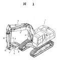
- 1 is a vehicle body for a normal power shovel
- 2 is a boom that can be raised and lowered
- 3 is an arm connected to the tip of the boom 2
- 4 and 5 are for raising and lowering them respectively.
- It is the cylinder apparatus for booms and arms.
- reference numeral 6 denotes a grapple bucket device attached to the tip of the arm 3.
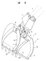
- the grapple bucket device 6 includes a bracket 7 that is pivotably connected to the tip of the arm 3 in the vertical direction, and a shaft in the extending direction of the arm 3 at the tip of the bracket 7.
- the bucket 8 is supported rotatably around the center, and the grapple device 9 is provided at the base end of the opening of the bucket 8 so as to be rotatable in a direction facing the opening of the bucket 8. Yes.
- a bucket cylinder device 10 provided along the arm 3 is connected to the upper portion of the bracket 7 via a link mechanism 11.
- the bucket 8 is rotated by a hydraulic motor 12 provided in the bracket 7 via a ring gear and a pinion (not shown).
- a plurality of excavation claws 8 a are provided at the tip of the bucket 8.
- the grapple device 9 includes a rotating shaft 14 pivotally supported in parallel to the opening width direction of the bucket 8 on a bracket 13 provided at a proximal end portion of the opening portion of the bucket 8, and a base portion fixed to both ends of the rotating shaft 14. And two grapple members 15a and 15b that are concavely curved facing the opening of the bucket 8. And the front-end
- the gap between the two grapple members 15a and 15b is substantially the same as the opening width of the bucket 8, but the gap between the tip portions of both members is narrower than the inner dimension of the bucket 8, and these tip portions are the bucket 8 A small gap is entered inside the bucket 8 along the inner wall surface.
- the connecting plate 16 at this time is located on the back side from the excavation claw 8a (the front end edge of the bucket when there is no excavation claw 8a) and extends along the bottom wall surface of the bucket 8 with a small gap. ing.
- the outer stepped portions of the portions where the thicknesses of both the grapple members 15 a and 15 b change are stoppers 17 that abut against the opening edge of the bucket 8.
- the connecting plate 16 is provided with a saw blade-like gripping blade 16a. Note that the gripping blade 16a of the connecting plate 16 may be linear.
- a bracket 18 protrudes from the rotary shaft 14, and the other end of the grapple cylinder device 19 pivotally supported in the bracket 13 provided at one end of the bracket 18 at the base end of the bucket 8.
- the grapple members 15 a and 15 b are rotated with respect to the bucket 8 by the expansion and contraction of the cylinder device 19.
- the grapple bucket device 6 configured in this manner causes the boom, arm and bucket cylinder devices 4, 5 and 10 to expand and contract to swing the boom 2 and arm 3 and rotate the bucket 8. As a result, the vertical position and posture of the grapple bucket device 6 are changed, and the posture of the bucket 8 in the left-right direction is changed by rotating the bucket 8 with respect to the bracket 7.
- the grapple cylinder device 19 is expanded and contracted to rotate the grapple members 15 a and 15 b with respect to the bucket 8.
- the wood 20 is grappled between the grapple members 15 a and 15 b and both side walls of the opening of the bucket 8.
- the wood plate 20 is pinched and lifted by the connecting plate 16 and the tip of the bucket 8 or the direction thereof is changed so as to make it easy to grapple.
- the grapple cylinder device 19 When excavating the ground, the grapple cylinder device 19 is extended to rotate the grapple members 15a and 15b toward the bucket 8 side. As a result, as shown by the solid line in FIG. 3, the tip ends of the grapple members 15 a and 15 b enter the bucket 8 along the inner surfaces on both sides of the bucket 8, and the connecting plate 16 is also on the back side of the excavation claw 8 a of the bucket 8. Then, it follows the bottom wall surface of the bucket 8.
- the conventional grapple bucket device can perform both excavation of the ground and grapple of wood, and in particular, by running the construction machine in a state where the wood is grappled, the wood can be accumulated in a predetermined place. We were able to expect a working effect.
- the worker had to cut the wood having a length longer than a predetermined length to a predetermined length by using a cutting device such as a chainsaw.
- the present invention has been made in view of the above, so that a grapple material such as wood that has been grappled by a grapple device can be cut in a grappled state, and the grapple material after cutting or a standing tree before cutting. Can be cut and felled easily to reduce the burden on the above workers, and before transporting the grapple material grappled by the grapple device, if it is long, it is cut in advance in a grappled state.
- An object of the present invention is to provide a grapple bucket device that can be transported without causing a trouble such as the grapple material coming into contact with another object.
- a grapple bucket device is provided at the tip of an arm of a construction machine that rotates in the vertical direction, and is pivotable in the vertical direction with respect to the axis in the extension direction of the arm.
- a grapple member that can grapple wood and other grapple materials between the bucket that is made rotatable and the opening surface of this bucket is turned to the base end of the bucket opening, and the bucket opening is closed.
- a cutting device for cutting a grapple material grappled by the grapple member is provided on one side wall portion of the bucket, and this cutting device is a bucket
- the side along the side wall from the position away from the opening edge of the bucket to the position along the side wall of the bucket, located on the outer side or the inner side of the side wall of the bucket A cutting blade pivotally supported at the base end of the opening of the bucket and having a cutting blade on the side edge opposite to the opening edge of the bucket, and provided on the back surface of the bucket
- a hydraulic cylinder connected to an arm provided at the rotation base of the cutting blade.
- a press receiving frame that allows the cutting blade to be immersed is provided on the side wall of the bucket, and the grapple material to be cut by the cutting blade is received by this press receiving frame.
- the cutting blade is provided at a position shifted toward the cutting direction of the cutting blade with respect to the line connecting the rotation center of the cutting blade and the connecting point of the hydraulic cylinder, and the cutting blade is rotated in the cutting direction. It was made the structure which curved backward in the arc shape with respect to the moving direction.
- the grapple device is connected to the front end portions of the two grapple members separated from each other by substantially the same interval as the opening width of the bucket and the front end portion enters the bucket or comes into contact with the front end of the bucket.
- a cover member such as a plate member or a lattice member is provided between the two grapple members whose tip portions are connected by a connecting member.
- a grapple material such as wood that has been grappled at the opening side of the bucket by the grapple bucket device can be cut by the cutting device while being grappled by the grapple device.
- the timber after cutting can be easily cut by the cutting device of this grapple bucket device, and the burden on the worker can be reduced. And before conveying the grapple material to be grappled by the grapple device, if this is long, it is possible to prevent troubles such as the grapple material coming into contact with other objects by cutting it in advance. .
- a standing tree before cutting can be easily cut in a state where the standing tree is grappled by a grapple device, and the labor can be reduced in a short period of time and compared with the cutting work by a chain saw or the like. Logging can be done without need.
- the grapple material is finely covered by the cover member while grapple the grapple material by the grapple device. Can be scooped up.
- FIG. 1 is a perspective view showing a state in which a conventional grapple bucket device is mounted on a work machine.
- FIG. 2 is a perspective view showing an example of a conventional grapple bucket device.
- FIG. 3 is a side view showing an example of a conventional grapple bucket device.
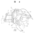
- FIG. 4 is a partially broken side view showing an embodiment of the grapple bucket device according to the present invention.
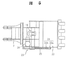
- FIG. 5 is a top view showing an embodiment of the grapple bucket device according to the present invention.
- 6 is a cross-sectional configuration diagram taken along line VI-VI in FIG.
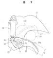
- FIG. 7 is an explanatory diagram showing the position of the cutting blade of the cutting blade with respect to a line connecting the rotation center of the cutting blade and the connecting point of the hydraulic cylinder.
- FIG. 1 is a perspective view showing a state in which a conventional grapple bucket device is mounted on a work machine.
- FIG. 2 is a perspective view showing an example of a conventional grapple bucket device.
- FIG. 3 is a side
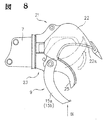
- FIG. 8 is a side view showing an example in which the cutting blade is provided on the inner side of the side wall of the bucket.
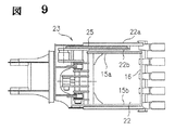
- 9 is a view taken in the direction of the arrow IX in FIG.
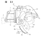
- FIG. 10 is a partially broken side view showing another example of the grapple member.
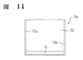
- 11 is a view taken in the direction of the arrow XI in FIG. FIG.
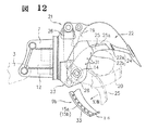
- It is a partially broken side view which shows the other example of a grapple member.
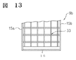
- 13 is a view taken in the direction of the arrow XII in FIG.
- FIG. 14 is a side view showing another example of the grapple member.
- the grapple bucket apparatus which concerns on this invention adds the cutting device to the above-mentioned conventional grapple bucket apparatus, and attaches
- the grapple bucket device 21 attached to the tip of the arm 3 includes a bracket 7 connected to the tip of the arm 3 so as to be pivotable in the vertical direction, and a central axis of the extension direction of the arm 3 at the tip of the bracket 7.
- the bucket 22 rotatably supported, the grapple device 9 provided at the base end of the opening of the bucket 22 so as to be rotatable in the direction facing the opening of the bucket 22, and the width direction of the bucket 22
- the cutting device 23 is provided on the right side when the opening is viewed from behind.
- the bucket 22 has substantially the same structure as the conventional bucket 8 described above.
- the cutting device 23 includes a right-hand side wall 22a of the bucket 22, a press-cut receiving frame 24 including the side wall 22a and a frame wall 22b provided outside the side wall 22a at a predetermined interval.
- a cutting blade 25 that is rotatably supported by the rotation shaft 14 of the grapple device 9 and a cylinder device 26 that is provided on the back surface of the bucket 22 and drives the cutting blade 25 to rotate. It has become.
- the shape on the open side of the press receiving frame 24 constituted by the side wall 22a and the frame wall 22b is the same as the shape on the open side of the bucket 22, that is, a concave arc shape, and the grapple member 15a of the grapple device 9 It has a shape along the outer periphery of the wood 20 grappled at 15b.
- a boss member (rotation base) 27 of the cutting blade 25 is pivotally supported by a rotating shaft 14 rotated by the cylinder device 19 of the grapple device 9, and protrudes from the boss member 27.
- the tip of the cylinder device 26 is connected to the provided arm 28, and the cutting blade 25 is rotated in the direction in which it protrudes and retracts with respect to the push-cut receiving frame 24 by the expansion and contraction of the cylinder device 26.
- the cutting blade 25 is attached to a disk member 29 fixed to the boss member 27 with a bolt.
- the cutting blade 25 has a cutting edge 25a on the side edge that is immersed in the push-cut receiving frame 24.
- the cutting blade 25a is warped in an arc shape in the backward direction with respect to the rotation direction toward the push-cut receiving frame 24, and has a so-called blue dragon blade shape.
- the cutting blade 25 a of the cutting blade 25 is dimensioned toward the opening edge side of the bucket 22 with respect to a line connecting the connection point O ⁇ b> 2 between the rotation center O ⁇ b> 1 of the cutting blade 25 and the hydraulic cylinder 26 of the arm 28. It is provided at a position shifted by a.
- the cylinder device 26 of the cutting device 23 is extended to close the cutting blade 25 toward the bucket 22 side.
- the wood 20 is cut and cut by the cutting blade 25.
- by rotating the bucket 22 with respect to the arm 3 and changing the posture of the bucket 22, either in the case of being felled and lying down, or in the form of a standing tree before cutting Wood can also be cut by the cutting device 23.
- the wood 20 at this time is supported by the press receiving frame 24 on the bucket 22 side, and the cutting blade 25 is operated toward the space between the frames of the press receiving frame 24, whereby the wood 20 is subjected to a cutting force by the cutting blade 25. Even if it is received, it is supported by the push-cut receiving frame 24 without being inclined.
- the cutting blade 25a of the cutting blade 25 is bent backward in a circular arc shape with respect to the rotation direction in the cutting direction, and the cutting blade 25a of the cutting blade 25 is connected to the rotation center O1 of the cutting blade 25.
- the wood 20 that has been grappled by the grapple device 9 is smoothed by the cutting blade 25 by being shifted to the cutting direction side with respect to the line connecting the connecting point O2 of the arm 28 to the hydraulic cylinder 26. Can be cut and cut.
- a spacer 30 is attached to the inside of the frame wall 24b of the push-cut receiving frame 24 to adjust this interval.
- the spacer 30 is attached by fixing it with bolts using bolt holes 31 provided in the frame wall 22b along the inner surface of the frame wall 22b.
- the cutting blade 25 is preferably located at the center of the facing interval of the push-cut receiving frame 24.
- the example in which one side wall 22a of the bucket 3 is used as the inner frame wall of the push-cut receiving frame 24 is shown.
- the inner frame wall of the push-cut receiving frame 24 is the bucket 3 You may make it comprise with another board
- the side wall 22a and the frame wall 22b of the bucket 22 form the push-cut receiving frame 24, and the wood 20 is supported by the push-cut receiving frame 24.
- the wood 20 to be cut is shown.
- the push receiving frame 24 may be configured only by the side wall 22 a of the bucket 22.
- the cutting blade 25 shown in FIG. 6 has the same thickness as the portion other than the cutting blade 25a.
- the thickness of the portion other than the cutting blade is tapered from the boss to the tip. Therefore, the sharpness of the cutting blade 25 can be expected to be improved.
- FIG. 8 and subsequent figures show different embodiments with respect to the above-described embodiment.
- the cutting blade 25 is arranged inside the side wall 22 a of the basket 8.
- the frame wall 22 b of the push frame 24 is provided inside the bucket 8.
- the grapple members 15 a and 15 b of the grapple device 9 enter the inside of the bucket 22.
- the grapple device 9a shown in FIG. 10 and FIG. 11 has a configuration in which the left and right grapple members 15a and 15b are closed by a plate member 32. It has become.
- the plate member 32 when the grapple device 9a is closed, the plate member 32 can cover the object in the grapple bucket device 6 together with the left and right grapple members 15a and 15b. Further, an object can be scooped on the plate member 32 inside the grapple device 9a.
- the grapple device 9b shown in FIGS. 12 and 13 has a structure in which the left and right grapple members 15a and 15b are closed by a lattice member 33.
- an object can be scooped into the grapple device 9b as in the case shown in FIGS. 10 and 11, and the scooped object can be screened by the lattice member 33. it can.
- the tip portions of the grapple members 15a, 15b of the grapple devices 9, 9a, 9b enter the inside of the bucket 8.
- the grapple device 9c shown in FIG. , 15b is aligned with the tip of the bucket 8, and the tip is in contact with the tip of the bucket 8.
- the excavation claw is not provided at the front end of the bucket 8 and has a straight front end edge.
- the left and right grapple members 15a and 15b of the grapple device 9c are simply spaces, or are closed with plate members or lattice members.
Landscapes
- Engineering & Computer Science (AREA)
- Mechanical Engineering (AREA)
- Mining & Mineral Resources (AREA)
- Civil Engineering (AREA)
- General Engineering & Computer Science (AREA)
- Structural Engineering (AREA)
- Shovels (AREA)
- Load-Engaging Elements For Cranes (AREA)
- Operation Control Of Excavators (AREA)
Abstract
Description
図2は、従来のグラップルバケット装置の一例を示す斜視図である。
図3は、従来のグラップルバケット装置の一例を示す側面図である。
図4は、本発明によるグラップルバケット装置の実施の形態を示す一部破断側面図である。
図5は、本発明によるグラップルバケット装置の実施の形態を示す上面図である。
図6は、図4のVI−VI線に沿う断面構成図である。
図7は、切断刃の回動中心と油圧シリンダとの連結点とを結ぶ線に対する切断刃の切刃の位置を示す説明図である。
図8は、切断刃をバケットの側壁の内側に設けた例を示す側面図である。
図9は、図8のIX方向矢視図である。
図10は、グラップル部材の他例を示す一部破断側面図である。
図11は、図10のXI方向矢視図である。
図12は。グラップル部材の他例を示す一部破断側面図である。
図13は、図12のXII方向矢視図である。
図14は、グラップル部材の他例を示側面図である。
Claims (4)
- 上下方向に回動する建設機械のアームの先端部に、上下方向に回動可能に且つアームの延長方向の軸心に対して回転可能にして設けたバケットと、このバケットの開口面との間で木材等の被グラップル材をグラップルできるグラップル部材をバケットの開口部の基端部に、バケットの開口部を閉じる方向に回動可能に枢支してなるグラップル装置とを設けたグラップルバケット装置において、
バケットの一方の側壁部に、上記グラップル部材にてグラップルした被グラップル材を切断する切断装置を設け、
この切断装置が、
バケットの側壁の外側あるいは内側の一方側に位置してバケットの開口縁から離れた位置からバケットの側壁に沿う位置にわたって側壁に沿う方向に回動するようにバケットの開口部の基端部に枢支され、且つバケットの開口縁側に対向する側の側縁に切刃を有している切断刃と、バケットの背面部に設けられていて上記切断刃の回動基部に設けたアームに連結された油圧シリンダとから構成されている
ことを特徴とするグラップルバケット装置。 - バケットの側壁部に、切断刃を没入可能にした押し切り受け枠を設け、切断刃にて切断する被グラップル材をこの押し切り受け枠にて受けるようにしたことを特徴とする請求項1記載のグラップルバケット装置。
- 切断刃の切刃を、切断刃の回動中心と油圧シリンダの連結点を結ぶ線に対して切断刃の切断方向側にずれた位置に設けると共に、この切刃を切断方向への回動方向に対して後方へ円弧状に反らせたことを特徴とする請求項1,2のいずれか1項記載のグラップルバケット装置。
- グラップル装置が、バケットの開口幅と略同一間隔に離隔し、且つ先端部がバケット内に入り込むか、又はバケットの先端に当接するようにした2本のグラップル部材の先端部を連結部材にて連結した構成、或いは先端部を連結部材にて連結した上記2本のグラップル部材間に板部材または格子部材等のカバー部材を設けた構成になっていることを特徴とする請求項1,2,3のいずれか1項記載のグラップルバケット装置。
Priority Applications (6)
| Application Number | Priority Date | Filing Date | Title |
|---|---|---|---|
| CN201180047219.1A CN103140629B (zh) | 2010-09-30 | 2011-09-30 | 抓斗装置 |
| PH1/2013/500551A PH12013500551A1 (en) | 2010-09-30 | 2011-09-30 | Grapple bucket apparatus |
| US13/877,046 US8919017B2 (en) | 2010-09-30 | 2011-09-30 | Grapple bucket apparatus |
| EP11829438.8A EP2623678B1 (en) | 2010-09-30 | 2011-09-30 | Grapple bucket device |
| KR1020137010984A KR101672083B1 (ko) | 2010-09-30 | 2011-09-30 | 그래플 버킷 장치 |
| HK13110426.8A HK1183075B (en) | 2010-09-30 | 2011-09-30 | Grapple bucket device |
Applications Claiming Priority (4)
| Application Number | Priority Date | Filing Date | Title |
|---|---|---|---|
| JP2010-221820 | 2010-09-30 | ||
| JP2010221820 | 2010-09-30 | ||
| JP2011212598A JP5911250B2 (ja) | 2010-09-30 | 2011-09-28 | グラップルバケット装置 |
| JP2011-212598 | 2011-09-28 |
Publications (1)
| Publication Number | Publication Date |
|---|---|
| WO2012043888A1 true WO2012043888A1 (ja) | 2012-04-05 |
Family
ID=45893313
Family Applications (1)
| Application Number | Title | Priority Date | Filing Date |
|---|---|---|---|
| PCT/JP2011/073157 Ceased WO2012043888A1 (ja) | 2010-09-30 | 2011-09-30 | グラップルバケット装置 |
Country Status (9)
| Country | Link |
|---|---|
| US (1) | US8919017B2 (ja) |
| EP (1) | EP2623678B1 (ja) |
| JP (1) | JP5911250B2 (ja) |
| KR (1) | KR101672083B1 (ja) |
| CN (1) | CN103140629B (ja) |
| MY (1) | MY162672A (ja) |
| PH (1) | PH12013500551A1 (ja) |
| TW (1) | TWI585270B (ja) |
| WO (1) | WO2012043888A1 (ja) |
Cited By (1)
| Publication number | Priority date | Publication date | Assignee | Title |
|---|---|---|---|---|
| JP2013245484A (ja) * | 2012-05-25 | 2013-12-09 | Muroto Tekkosho:Kk | グラップル装置 |
Families Citing this family (19)
| Publication number | Priority date | Publication date | Assignee | Title |
|---|---|---|---|---|
| WO2015109092A1 (en) * | 2014-01-16 | 2015-07-23 | Honermann Michael A | Skid loader attachment including a rotatable and extendable claw |
| EP3116300B1 (en) * | 2014-03-14 | 2019-05-01 | Koponen, Tenho | Energy wood grapple |
| US9439363B1 (en) * | 2015-04-27 | 2016-09-13 | Caterpillar Forest Products Inc. | Bracket system for grapple assembly |
| CN105823855A (zh) * | 2016-04-19 | 2016-08-03 | 长江大学 | 一种省力切割小推车及使用方法 |
| JP6976739B2 (ja) * | 2017-06-27 | 2021-12-08 | 良三 松本 | 伐倒切断機 |
| US10279486B2 (en) | 2017-07-12 | 2019-05-07 | Tidy Site Services, LLC | Construction equipment accessory and methods of moving elongate objects |
| JP7034455B2 (ja) * | 2017-10-18 | 2022-03-14 | Nty工業株式会社 | 表層材剥離装置 |
| CN107840389A (zh) * | 2017-11-24 | 2018-03-27 | 长兴华阁耐物流装备有限公司 | 一种便于移动的格栅除污机 |
| KR102140832B1 (ko) * | 2018-06-29 | 2020-08-11 | (주)대동이엔지 | 수목제거 및 지뢰 제거장치 |
| KR200491013Y1 (ko) * | 2018-07-16 | 2020-02-06 | 이상경 | 수목 이식용 버킷 |
| KR102145621B1 (ko) * | 2018-11-22 | 2020-08-18 | 이창업 | 굴착기용 안전 집게 가위 |
| CN109403407A (zh) * | 2018-12-06 | 2019-03-01 | 北京市政建设集团有限责任公司 | 一种适用于卵石地层的液压抓斗 |
| CN112049160B (zh) * | 2020-09-09 | 2022-04-29 | 中电建路桥集团有限公司 | 低扰动快速施工用反铲式挖掘机 |
| CN112709272B (zh) * | 2020-12-24 | 2022-10-04 | 山东威猛工程机械有限公司 | 一种建筑垃圾装载用铲斗 |
| JP2022182492A (ja) * | 2021-05-28 | 2022-12-08 | オカダアイヨン株式会社 | グラップルバケット装置 |
| JP2023082256A (ja) * | 2021-12-02 | 2023-06-14 | 株式会社アイチコーポレーション | 穴掘建柱車のアタッチメント装置 |
| JP7788363B2 (ja) * | 2022-10-07 | 2025-12-18 | オカダアイヨン株式会社 | グラップルバケット装置及び木の切断方法 |
| US12590435B2 (en) * | 2023-12-05 | 2026-03-31 | Fields Log Master LLC | Tractor attachment accessories |
| CN119566031B (zh) * | 2025-02-08 | 2025-04-18 | 永兴阳光贵金属有限公司 | 一种废旧金属回收处理用压缩机 |
Citations (5)
| Publication number | Priority date | Publication date | Assignee | Title |
|---|---|---|---|---|
| CA1080586A (en) * | 1979-01-05 | 1980-07-01 | Koehring Canada Limited | Tree harvester with saw and shear |
| JPH06306884A (ja) * | 1993-04-27 | 1994-11-01 | Ishikawajima Constr Mach Co | バケット |
| JPH06343356A (ja) * | 1993-06-11 | 1994-12-20 | Hitachi Constr Mach Co Ltd | 根切りアタッチメント |
| JPH1136355A (ja) | 1997-07-17 | 1999-02-09 | Yamakawa Eng Kk | グラップルバケット装置 |
| JP2008133640A (ja) * | 2006-11-28 | 2008-06-12 | Tomi Matsui | 枝切り走行装置 |
Family Cites Families (14)
| Publication number | Priority date | Publication date | Assignee | Title |
|---|---|---|---|---|
| US3731720A (en) * | 1970-07-27 | 1973-05-08 | Caterpillar Tractor Co | Shear assembly for tree harvesters |
| SE418919C (sv) * | 1975-10-07 | 1986-06-09 | Umea Mekaniska Ab | Tredfellningsaggregat |
| US4221245A (en) * | 1979-01-19 | 1980-09-09 | Koehring Canada Limited | Tree harvester with saw and shear |
| US4384599A (en) * | 1979-08-06 | 1983-05-24 | Dagenais Joseph E | Slicing apparatus for felling trees |
| DE3151871A1 (de) * | 1981-02-19 | 1982-09-02 | Ernst Menzi AG, 9443 Widnau | "vorrichtung zum abtrennen von baumstaemmen" |
| JP2649703B2 (ja) * | 1988-07-26 | 1997-09-03 | 博 小野寺 | ショベル系掘削機のフロントアタッチメント |
| JPH09302707A (ja) * | 1996-05-14 | 1997-11-25 | Toyo Umpanki Co Ltd | バケット装置 |
| SE513257C2 (sv) * | 1997-06-04 | 2000-08-07 | Elmek Automation Ab | Trädskördeaggregat |
| US6655053B1 (en) | 1998-08-25 | 2003-12-02 | Rockland, Inc. | Tool attachment for excavating machines and the like |
| JP2002017325A (ja) * | 2000-07-10 | 2002-01-22 | Ichiro Yokota | 野菜・果実切断装置 |
| US6779570B2 (en) * | 2002-11-06 | 2004-08-24 | Daniel Tardif | Wood gathering and compaction vehicle |
| JP2007146470A (ja) * | 2005-11-28 | 2007-06-14 | Ueda Sangyo Kk | マグネット付きバケット |
| US7526885B2 (en) * | 2005-12-13 | 2009-05-05 | Peterson Pacific Corporation | Splitter grappler |
| US20090229433A1 (en) * | 2008-03-13 | 2009-09-17 | Elijah Kovalenko | Cutting Tool and Construction Equipment Therfore |
-
2011
- 2011-09-28 JP JP2011212598A patent/JP5911250B2/ja active Active
- 2011-09-30 WO PCT/JP2011/073157 patent/WO2012043888A1/ja not_active Ceased
- 2011-09-30 EP EP11829438.8A patent/EP2623678B1/en active Active
- 2011-09-30 US US13/877,046 patent/US8919017B2/en active Active
- 2011-09-30 CN CN201180047219.1A patent/CN103140629B/zh active Active
- 2011-09-30 PH PH1/2013/500551A patent/PH12013500551A1/en unknown
- 2011-09-30 KR KR1020137010984A patent/KR101672083B1/ko active Active
- 2011-09-30 TW TW100135610A patent/TWI585270B/zh active
- 2011-09-30 MY MYPI2013000978A patent/MY162672A/en unknown
Patent Citations (5)
| Publication number | Priority date | Publication date | Assignee | Title |
|---|---|---|---|---|
| CA1080586A (en) * | 1979-01-05 | 1980-07-01 | Koehring Canada Limited | Tree harvester with saw and shear |
| JPH06306884A (ja) * | 1993-04-27 | 1994-11-01 | Ishikawajima Constr Mach Co | バケット |
| JPH06343356A (ja) * | 1993-06-11 | 1994-12-20 | Hitachi Constr Mach Co Ltd | 根切りアタッチメント |
| JPH1136355A (ja) | 1997-07-17 | 1999-02-09 | Yamakawa Eng Kk | グラップルバケット装置 |
| JP2008133640A (ja) * | 2006-11-28 | 2008-06-12 | Tomi Matsui | 枝切り走行装置 |
Non-Patent Citations (1)
| Title |
|---|
| See also references of EP2623678A4 |
Cited By (1)
| Publication number | Priority date | Publication date | Assignee | Title |
|---|---|---|---|---|
| JP2013245484A (ja) * | 2012-05-25 | 2013-12-09 | Muroto Tekkosho:Kk | グラップル装置 |
Also Published As
| Publication number | Publication date |
|---|---|
| CN103140629B (zh) | 2016-10-12 |
| US20130192098A1 (en) | 2013-08-01 |
| JP2013163889A (ja) | 2013-08-22 |
| KR101672083B1 (ko) | 2016-11-02 |
| PH12013500551A1 (en) | 2013-05-06 |
| EP2623678A1 (en) | 2013-08-07 |
| TWI585270B (zh) | 2017-06-01 |
| EP2623678B1 (en) | 2018-03-07 |
| CN103140629A (zh) | 2013-06-05 |
| HK1183075A1 (zh) | 2013-12-13 |
| MY162672A (en) | 2017-06-30 |
| JP5911250B2 (ja) | 2016-04-27 |
| US8919017B2 (en) | 2014-12-30 |
| EP2623678A4 (en) | 2014-05-07 |
| TW201229362A (en) | 2012-07-16 |
| KR20130113463A (ko) | 2013-10-15 |
Similar Documents
| Publication | Publication Date | Title |
|---|---|---|
| WO2012043888A1 (ja) | グラップルバケット装置 | |
| JP4091100B1 (ja) | 竹伐採用アタッチメント及びそれを備えた竹伐採作業機 | |
| JP6687494B2 (ja) | トンネル掘進機 | |
| KR101776408B1 (ko) | 집혀진 원목을 이격시켜 절단이 가능한 굴삭기용 원목 절단장치 | |
| JP5469982B2 (ja) | グラップル装置及び油圧ショベル | |
| JP7554246B2 (ja) | 伐採作業機 | |
| JP2024094643A (ja) | グラップルバケット装置 | |
| JP3567961B2 (ja) | グラップルバケット装置 | |
| JP7543526B1 (ja) | 掘削グラップル装置及び油圧ショベル | |
| HK1183075B (en) | Grapple bucket device | |
| KR101269133B1 (ko) | 수목 이식용 굴취장치 | |
| JP2003018928A (ja) | 根切りアタッチメントと根切り作業機 | |
| JPH11181817A (ja) | グラップルバケット装置 | |
| FR2924305A1 (fr) | Outil d'essouchement apte a extraire et a debiter sur site les souches d'arbre | |
| JP2002335733A (ja) | 伐採物移動機構を備えた草刈り機 | |
| JPS5898529A (ja) | パワ−シヨベルのロツクバケツト | |
| EP4440298B1 (en) | Auxiliary beam for an energy wood grapple and a system and method for harvesting energy wood | |
| JP7852131B1 (ja) | 伐採作業機及び油圧ショベル | |
| JP5495923B2 (ja) | 把持機能付きバケット装置 | |
| JP2001161189A (ja) | パワーカッタ | |
| JP2004183322A (ja) | 多機能重機 | |
| JPH071957Y2 (ja) | 枝払カッター | |
| JP2007284986A (ja) | ショベル系掘削機の切断又は把持用アタッチメント | |
| JP2665126B2 (ja) | プロセッサヘッドの枝払機構 | |
| JPH03122320A (ja) | 掘削バケット装置 |
Legal Events
| Date | Code | Title | Description |
|---|---|---|---|
| WWE | Wipo information: entry into national phase |
Ref document number: 201180047219.1 Country of ref document: CN |
|
| 121 | Ep: the epo has been informed by wipo that ep was designated in this application |
Ref document number: 11829438 Country of ref document: EP Kind code of ref document: A1 |
|
| DPE1 | Request for preliminary examination filed after expiration of 19th month from priority date (pct application filed from 20040101) | ||
| WD | Withdrawal of designations after international publication |
Designated state(s): JP |
|
| WWE | Wipo information: entry into national phase |
Ref document number: 12013500551 Country of ref document: PH |
|
| WWE | Wipo information: entry into national phase |
Ref document number: 13877046 Country of ref document: US |
|
| NENP | Non-entry into the national phase |
Ref country code: DE |
|
| WWE | Wipo information: entry into national phase |
Ref document number: 2011829438 Country of ref document: EP |
|
| ENP | Entry into the national phase |
Ref document number: 20137010984 Country of ref document: KR Kind code of ref document: A |