WO2012046410A1 - Pmモータの電流制御ゲイン調整方法、電流制御方法および制御装置 - Google Patents
Pmモータの電流制御ゲイン調整方法、電流制御方法および制御装置 Download PDFInfo
- Publication number
- WO2012046410A1 WO2012046410A1 PCT/JP2011/005446 JP2011005446W WO2012046410A1 WO 2012046410 A1 WO2012046410 A1 WO 2012046410A1 JP 2011005446 W JP2011005446 W JP 2011005446W WO 2012046410 A1 WO2012046410 A1 WO 2012046410A1
- Authority
- WO
- WIPO (PCT)
- Prior art keywords
- motor
- current
- current control
- control gain
- voltage
- Prior art date
- Legal status (The legal status is an assumption and is not a legal conclusion. Google has not performed a legal analysis and makes no representation as to the accuracy of the status listed.)
- Ceased
Links
Images





Classifications
-
- H—ELECTRICITY
- H02—GENERATION; CONVERSION OR DISTRIBUTION OF ELECTRIC POWER
- H02P—CONTROL OR REGULATION OF ELECTRIC MOTORS, ELECTRIC GENERATORS OR DYNAMO-ELECTRIC CONVERTERS; CONTROLLING TRANSFORMERS, REACTORS OR CHOKE COILS
- H02P21/00—Arrangements or methods for the control of electric machines by vector control, e.g. by control of field orientation
- H02P21/05—Arrangements or methods for the control of electric machines by vector control, e.g. by control of field orientation specially adapted for damping motor oscillations, e.g. for reducing hunting
-
- H—ELECTRICITY
- H02—GENERATION; CONVERSION OR DISTRIBUTION OF ELECTRIC POWER
- H02P—CONTROL OR REGULATION OF ELECTRIC MOTORS, ELECTRIC GENERATORS OR DYNAMO-ELECTRIC CONVERTERS; CONTROLLING TRANSFORMERS, REACTORS OR CHOKE COILS
- H02P21/00—Arrangements or methods for the control of electric machines by vector control, e.g. by control of field orientation
- H02P21/0003—Control strategies in general, e.g. linear type, e.g. P, PI, PID, using robust control
-
- H—ELECTRICITY
- H02—GENERATION; CONVERSION OR DISTRIBUTION OF ELECTRIC POWER
- H02P—CONTROL OR REGULATION OF ELECTRIC MOTORS, ELECTRIC GENERATORS OR DYNAMO-ELECTRIC CONVERTERS; CONTROLLING TRANSFORMERS, REACTORS OR CHOKE COILS
- H02P21/00—Arrangements or methods for the control of electric machines by vector control, e.g. by control of field orientation
- H02P21/0003—Control strategies in general, e.g. linear type, e.g. P, PI, PID, using robust control
- H02P21/0025—Control strategies in general, e.g. linear type, e.g. P, PI, PID, using robust control implementing a off line learning phase to determine and store useful data for on-line control
-
- H—ELECTRICITY
- H02—GENERATION; CONVERSION OR DISTRIBUTION OF ELECTRIC POWER
- H02P—CONTROL OR REGULATION OF ELECTRIC MOTORS, ELECTRIC GENERATORS OR DYNAMO-ELECTRIC CONVERTERS; CONTROLLING TRANSFORMERS, REACTORS OR CHOKE COILS
- H02P21/00—Arrangements or methods for the control of electric machines by vector control, e.g. by control of field orientation
- H02P21/14—Estimation or adaptation of machine parameters, e.g. flux, current or voltage
- H02P21/16—Estimation of constants, e.g. the rotor time constant
-
- H—ELECTRICITY
- H02—GENERATION; CONVERSION OR DISTRIBUTION OF ELECTRIC POWER
- H02P—CONTROL OR REGULATION OF ELECTRIC MOTORS, ELECTRIC GENERATORS OR DYNAMO-ELECTRIC CONVERTERS; CONTROLLING TRANSFORMERS, REACTORS OR CHOKE COILS
- H02P23/00—Arrangements or methods for the control of AC motors characterised by a control method other than vector control
- H02P23/0004—Control strategies in general, e.g. linear type, e.g. P, PI, PID, using robust control
- H02P23/0031—Control strategies in general, e.g. linear type, e.g. P, PI, PID, using robust control implementing a off line learning phase to determine and store useful data for on-line control
-
- H—ELECTRICITY
- H02—GENERATION; CONVERSION OR DISTRIBUTION OF ELECTRIC POWER
- H02P—CONTROL OR REGULATION OF ELECTRIC MOTORS, ELECTRIC GENERATORS OR DYNAMO-ELECTRIC CONVERTERS; CONTROLLING TRANSFORMERS, REACTORS OR CHOKE COILS
- H02P23/00—Arrangements or methods for the control of AC motors characterised by a control method other than vector control
- H02P23/14—Estimation or adaptation of motor parameters, e.g. rotor time constant, flux, speed, current or voltage
Definitions
- the present invention relates to a current control gain adjustment method, a current control method, and a control device for a PM motor having a current control system that detects and controls a motor current.
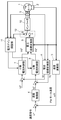
- FIG. 10 is a block diagram showing the configuration of a conventional motor control device for a PM motor.
- the motor control device for the PM motor includes at least a PM motor 101, a speed calculation unit 103, a speed control unit 104, a current detector 105, a current coordinate conversion unit 106, and a d-axis current control.
- the current coordinate conversion unit 106 performs coordinate conversion on the detected value of the motor current detected by the current detector 105, and a d-axis current Id that is a component in the same direction as the magnetic pole axis of the PM motor 101, and a direction perpendicular to the d-axis.
- Q-axis current Iq which is a component of, is calculated and output.
- the d-axis current control unit 107 calculates and outputs the d-axis voltage command Vd * so that the d-axis current Id follows the d-axis current command Id * given in advance.
- the q-axis current control unit 108 calculates and outputs a q-axis voltage command Vq * so that the q-axis current Iq follows the q-axis current command Iq *.
- the d-axis current control unit 107 and the q-axis current control unit 108 operate by, for example, proportional integral control.
- the current control gains of the d-axis current control unit 107 and the q-axis current control unit 108 are appropriately set to achieve stable current control. It needs to be realized. In order to obtain high speed controllability of the PM motor, it is desirable to set the current control gain of the current control system, which is a minor loop of the speed control system, as high as possible.
- Patent Document 1 proposes several techniques for adjusting a current control gain in a conventional PM motor control device.
- the technique disclosed in Patent Document 1 is intended for induction motors, and is based on an arithmetic expression using a resistance value and an inductance value, which are circuit constants (motor constants) of an equivalent circuit including a load, and a control delay time. Current control gain is determined.
- Patent Document 2 Another technique for obtaining a motor constant such as a resistance value or an inductance value is disclosed in Patent Document 2, for example.
- a resistance value is obtained from an input voltage and an input current when a direct current is passed through the PM motor 101.
- the input voltage and the fundamental component of the input current when an alternating current is passed through the PM motor 101 are extracted, and the inductance is determined from the magnitudes of the input voltage and the input current and the phase difference between the input voltage and the input current. Find the value.
- a current control gain is obtained from the obtained resistance value and inductance value.
- Patent Document 1 it is necessary to examine in advance the resistance value and the inductance value, which are equivalent circuit constants.
- the cut-off frequency that determines the current control response is calculated by a fixed formula, the current response may not always be maximized.
- Patent Document 2 it is possible to measure the motor constant, which is a problem of Patent Document 1. However, it takes time for the direct current flowing through the PM motor 101 to reach the steady state in order to obtain the winding resistance. In addition, since the resistance value and the inductance value are measured using separate test signals, there is a problem that measurement takes time.
- the PM motor current control gain adjustment method of the present invention includes a step of applying a voltage including a direct current component and a plurality of frequency components to the PM motor, a step of detecting a motor current flowing in accordance with the applied voltage, and the applied voltage and the motor. Calculating a current control gain that is stable and has high current responsiveness using frequency characteristics that are current relationships.
- FIG. 1 is a block diagram showing a configuration of a motor control device for a PM motor according to Embodiment 1 of the present invention.
- FIG. 2 is a flowchart showing a flow of processing for adjusting the current control gain of the current gain adjusting unit according to Embodiment 1 of the present invention.
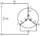
- FIG. 3 is an equivalent circuit diagram illustrating a single-phase energization state of the PM motor.
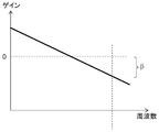
- FIG. 4A is a diagram illustrating a frequency characteristic of a transfer function (gain) of the PM motor.
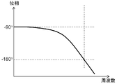
- FIG. 4B is a diagram illustrating frequency characteristics of a transfer function (phase) of the PM motor.
- FIG. 5A is a diagram illustrating a current-controlled open loop frequency characteristic.
- FIG. 5B is a diagram showing current control open loop frequency characteristics.
- FIG. 6 is a flowchart showing a flow of processing for adjusting the current control gain of the current gain adjustment unit in Embodiment 2 of the present invention.
- FIG. 7 is a diagram showing the relationship between the motor current and the electrical time constant in the same embodiment.
- FIG. 8 is a block diagram showing a configuration of a motor control device for a PM motor according to Embodiment 3 of the present invention.
- FIG. 9 is a flowchart showing the flow of processing in the third embodiment of the present invention.
- FIG. 10 is a block diagram showing the configuration of a conventional motor control device for a PM motor.
- Embodiment 1 A PM motor current control gain adjustment method and motor control apparatus according to Embodiment 1 of the present invention will be described below with reference to FIG.
- FIG. 1 is a block diagram showing a configuration of a motor control device for a PM motor according to Embodiment 1 of the present invention.
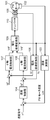
- the motor controller for a PM motor includes at least a PM motor 1, a speed calculation unit 3, a speed control unit 4, a current detector 5, and a current coordinate conversion unit 6. , D-axis current control unit 7, q-axis current control unit 8, voltage coordinate conversion unit 9, inverter 10, current gain adjustment unit 11, and voltage command switching unit 12.
- the motor controller for the PM motor shown in FIG. 1 drives the PM motor 1 by the following operation.
- the position detector 2 is attached to the PM motor 1 to detect the rotational position of the PM motor 1.
- the speed calculation unit 3 calculates the PM motor speed ⁇ m from the rotational position information of the PM motor 1 detected by the position detector 2.
- the speed control unit 4 controls the motor speed ⁇ m calculated by the speed calculation unit 3 to follow the speed command ⁇ *, and calculates and outputs a q-axis current command Iq *.
- the current detector 5 detects the motor current flowing through the PM motor 1.
- the current coordinate converter 6 converts the motor current detected by the current detector 5 into a d-axis current Id and a q-axis current Iq and outputs the converted current.
- the d-axis current control unit 7 performs control so that the d-axis current Id converted by the current coordinate conversion unit 6 follows the d-axis current command Id *, and calculates and outputs a d-axis voltage command Vd *.
- the q-axis current control unit 8 controls the q-axis current Iq converted by the current coordinate conversion unit 6 to follow the q-axis current command Iq *, and calculates and outputs a q-axis voltage command Vq *.
- the voltage coordinate conversion unit 9 converts the d-axis voltage command Vd * and the q-axis voltage command Vq * command into a three-phase voltage command.
- the inverter 10 applies a voltage corresponding to the input three-phase voltage command to the PM motor 1.
- the current gain adjustment unit 11 performs a current control gain adjustment process and sets the d-axis current control unit 7 and the q-axis current control unit 8.
- the voltage command switching unit 12 switches between the output of the voltage coordinate conversion unit 9 and the output of the current gain adjustment unit 11 as a three-phase voltage command input to the inverter 10. Note that the voltage command switching unit 12 is switched to the A side shown in FIG. 1 during speed control of the normal PM motor 1, and is switched to the B side shown in FIG. 1 during current control gain adjustment.
- the voltage command switching unit 12 of the motor driving device of the PM motor 1 is switched to the B side.
- the current gain adjustment unit 11 adjusts the current control gain of the output of the inverter 10 applied to the PM motor 1.
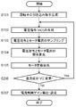
- FIG. 2 is a flowchart showing a flow of processing for adjusting the current control gain of the current gain adjusting unit in Embodiment 1 of the present invention.
- FIG. 3 is an equivalent circuit diagram illustrating a single-phase energization state of the PM motor.
- FIG. 4A is a diagram illustrating a frequency characteristic of a transfer function (gain) of the PM motor.
- FIG. 4B is a diagram illustrating frequency characteristics of a transfer function (phase) of the PM motor.
- step S101 when the adjustment process of the current control gain is started, a pull-in voltage command is generated and output in order to pull the rotor of the PM motor 1 into a predetermined position (step S101).
- the PM motor 1 has a magnet in the rotor, so that the rotor may be rotated by voltage application, and therefore the PM motor 1 rotor is fixed in a predetermined position in advance. Therefore, the calculation of the motor constant is preferably performed in a state where the rotor of the PM motor 1 is stationary.
- a DC voltage of Va, V-phase and -Va / 2 is applied to the U-phase, and the rotor of the PM motor 1 is pulled into a predetermined position.
- the DC voltage Va is set, for example, as a voltage when a current of about the rated current of the PM motor 1 flows when a voltage is applied so that the rotor of the PM motor 1 is sufficiently drawn into a predetermined position.
- an equivalent circuit of the PM motor 1 after the rotor of the PM motor 1 is pulled into a predetermined position is as shown in FIG. That is, as shown in FIG. 3, since the rotor of the PM motor 1 is not rotating, the equivalent circuit of the PM motor 1 is composed of a phase resistance R and a phase inductance L, and a single-phase voltage is applied between U-VW. Will be. As a result, the current axis (d-axis) and the magnetic pole axis coincide with each other.
- a voltage command Vs (t) that is an applied voltage to be applied to calculate a motor constant is generated (step S102). Specifically, a voltage command Vs (t) is generated by adding Vn (t) having a plurality of frequency components to the DC component V0 as shown in (Equation 1). At this time, for example, an M-sequence signal (Maximum Length Sequence Signal) is used as the voltage command Vn (t).
- an M-sequence signal Maximum Length Sequence Signal
- the single phase voltage is applied between U and VW in the same way as the pull-in, so that it is applied to the inverter 10, for example, Vs (t), V phase
- the voltage command Vs (t) of ⁇ Vs (t) / 2 is output to the W phase.
- the motor current that flows to the PM motor 1 by the voltage command Vs (t) flows to the same d axis as the magnetic pole shaft, so that no torque for rotating the rotor of the PM motor 1 is generated. Thereby, it is possible to perform data measurement for calculating the motor constant while the rotor of the PM motor 1 is stationary.
- step S102 the voltage command Vs (t) applied in step S102 and the motor current Is (t) as a response to the voltage command Vs (t) are sampled and taken in as time series data (step S103).
- the motor current Is (t) is a motor current with respect to a single-phase applied voltage applied between U and VW, the U-phase motor current is sampled.
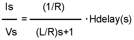
- the frequency characteristic of the transfer function H (s) from the voltage command Vs (t) to the motor current Is (t) is obtained as the relationship between the voltage command Vs (t) and the motor current Is (t) (step S104).
- the frequency characteristics of the transfer function H (s) can be obtained by processing the voltage command Vs (t) and the motor current Is (t) by FFT (Fast Fourier Transform) processing or the like.
- Hdelay (s) in the equation (2) is a time delay element of the current control system.
- FIG. 4A is a diagram showing a frequency characteristic of a transfer function (gain) of the PM motor.
- FIG. 4B is a diagram illustrating frequency characteristics of a transfer function (phase) of the PM motor.
- the reciprocal of the cut-off frequency R / L and the DC gain 1 / R is calculated to obtain the electrical time constant L / R and the phase resistance R, which are the motor constants of the PM motor (step S105).
- the electrical time constant obtained as described above is the electrical time constant on the d axis.
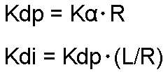
- a current control gain is calculated and set from the electrical time constant L / R, which is the motor constant of the PM motor obtained in step S105, and the phase resistance R.
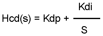
- the control of the d-axis current control unit 7 is proportional-integral control.
- the proportional gain is Kdp and the integral gain is Kdi
- the transfer function Hcd (s) of the d-axis current control unit 7 is expressed by the following equation (3). Become.
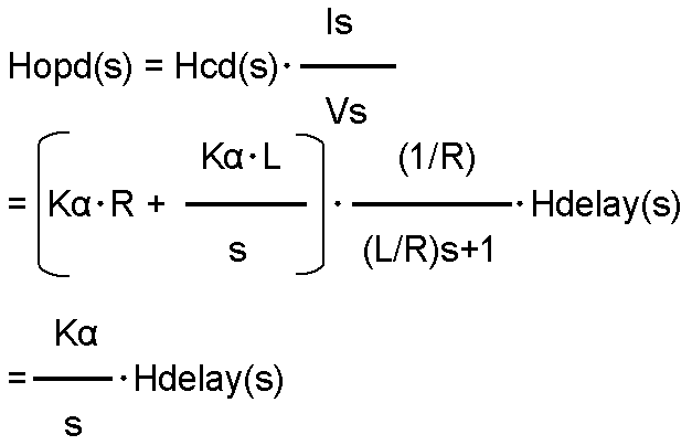
- Equation (5) The open transfer function Hopd (s) of the d-axis current control system is expressed by Equation (5).
- FIG. 5A is a diagram showing frequency characteristics of a current control open loop.
- FIG. 5B is a diagram illustrating frequency characteristics of a current-controlled open loop.
- the gain at a frequency at which the phase of the open transfer function Hopd (s) of the current control system is ⁇ 180 degrees is used. What is necessary is just to obtain
- an applied voltage including a direct current component and a plurality of frequency components is applied to the PM motor, and the motor current flowing according to the applied applied voltage is detected, thereby applying the voltage.
- the motor constant of the PM motor is calculated using the relationship between the applied voltage and the detected motor current. That is, the motor constant can be calculated simply by applying an applied voltage including a DC component and a plurality of frequency components and detecting the motor current. As a result, it is not necessary to wait for the motor current to reach a steady state, and it is not necessary to calculate a motor constant by applying a plurality of test signals, so that the time can be significantly reduced.
- the current control gain is theoretically calculated using the frequency characteristic that is the relationship between the voltage command and the motor current.
- the current control gain can be adjusted to have a stable and high current response.
- the frequency characteristic includes a time delay element in the current control system of the motor controller of the PM motor
- the current control gain can be stabilized in consideration of the variation of the time delay element by the motor controller. And it can adjust so that it may have high current responsiveness. High current responsiveness means that the set current command is reached in a short time.
- This embodiment is different from the first embodiment in that the current control gain is calculated and set by applying an applied voltage including a plurality of different DC components to the PM motor.
- Other configurations and operations are the same as those in the first embodiment, and thus description thereof is omitted.
- the electrical time constant which is a motor constant
- the electrical time constant varies depending on the influence of magnetic saturation and the magnitude of the motor current.
- only one current control gain value is calculated. For this reason, when the electrical time constant of the motor changes for the reason described above, the motor may not be controlled with a stable current control gain.
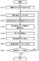
- FIG. 6 is a flowchart showing a flow of processing for adjusting the current control gain of the current gain adjustment unit in Embodiment 2 of the present invention.
- FIG. 7 is a diagram showing the relationship between the motor current and the electrical time constant in the same embodiment.
- steps S101 to S105 perform the same processing as in the first embodiment described with reference to FIG.
- step S206 and step S207 since the processing of step S206 and step S207 is further added to each step of FIG. 2, the added steps will be described in detail.
- step S206 when there is an unset value (applied voltage) among the applied voltages of the plurality of DC components V0 (Yes in step S206), an unset value (applied voltage) among the applied voltages of the plurality of DC components V0. ) Is selected, and the process returns to step S102. Then, the processing from step S102 to step S105 is sequentially repeated to extract the motor constant of the PM motor for each applied voltage of a plurality of DC components.
- step S206 when all the values of the applied voltages of the plurality of DC components V0 are executed (No in step S206), the process proceeds to step S207.
- step S105 for each combination of the motor constants of the plurality of PM motors obtained in step S105 and the plurality of frequency characteristics obtained in step S104, a stable and high current responsiveness K ⁇ is obtained, and the current control unit Calculate proportional gain and integral gain.
- the electrical time constant changes depending on the magnitude of the motor current due to the influence of magnetic saturation and the like. Therefore, in order to avoid the gain of the current control unit being too high and becoming unstable, among the combinations of the proportional gain and the integral gain of the plurality of current control units obtained by repeating the processing from step S102 to step S206. Choose the smallest one.
- the combination of the proportional gain and integral gain of the smallest selected current control unit is the gain with the highest current response under the condition of stably driving the PM motor. Therefore, the proportional gain and integral gain of the current control unit obtained from the above are set (step S207).
- an applied voltage including a plurality of direct current components and a plurality of frequency components is applied to the PM motor, and a plurality of motor currents flowing according to the applied plurality of applied voltages are detected.
- the electrical time constant of the PM motor is calculated using the relationship between the plurality of applied voltages and the detected motor current.
- Embodiment 3 A PM motor current control gain adjustment method, current control method, and motor control apparatus according to Embodiment 3 of the present invention will be described with reference to FIG. 8 that are the same as those in FIG. 1 are assigned the same reference numerals and descriptions thereof are omitted.
- a current gain setting unit 13 is added to the configuration of FIG.
- the current control gain is calculated and set as a fixed value in that the motor current is controlled by changing the current control gain according to the change of the electrical time constant due to the change of the motor current of the PM motor. This is different from the second form.
- an applied voltage including a plurality of different DC components is applied to the PM motor, and an electrical time constant corresponding to the motor current flowing through the PM motor is extracted according to the applied voltages. . Based on the extracted electrical time constant, a stable current control gain with high current response is calculated.
- a current control gain map is created from a plurality of current gains calculated according to the motor current in association with the average value of the motor current, and stored in a semiconductor memory, for example.
- the current control gain corresponding to the motor current is read from the stored current control gain map, the current gain setting unit 13 is set, and the motor current of the PM motor is controlled.
- FIG. 9 is a flowchart showing a flow of processing for adjusting the current control gain of the current gain adjusting unit according to Embodiment 3 of the present invention.
- steps S101 to S106 perform the same processing as in the first embodiment described with reference to FIG.
- step S308 performs the same processing as step S206 of the second embodiment described with reference to FIG.
- step S101 to step S105 is executed as in the first embodiment described in FIG.
- the current control gain is calculated from the electrical time constant L / R, which is the motor constant of the PM motor obtained in step S105, and the phase resistance R (step). S106).
- a current control gain map is created based on the relationship between the current control gain calculated for the applied voltage of the predetermined DC component V0 and the average value of the detected motor current.
- step S308 it is determined whether or not all the applied voltages of the plurality of DC components V0 are set in the generation of the voltage command in step S102 (step S308).
- the applied voltages of the plurality of DC components V0 are set in advance from zero to a voltage value when the maximum current that is the specification of the PM motor 1 flows.
- step S308 when there is an unset value (applied voltage) among the applied voltages of a plurality of DC components V0 (Yes in step S308), an unset value (applied) among the applied voltages of a plurality of DC components V0. Voltage) is selected, and the process returns to step S102. Then, the processes from step S102 to step S307 are sequentially repeated. As a result, a plurality of current control gain maps are created based on the relationship between the average value of the motor current of the PM motor for each applied voltage of a plurality of DC components V0 and the calculated current control gain. Store in a storage medium.
- the motor control device sets the current control gain according to the motor current based on the current control gain map stored by the above processing, and sets the motor current. Control and drive the PM motor.
- the present invention is not limited to this.
- the motor current may be controlled by changing the current control gain according to the motor current command.
- the method for calculating and setting the current control gain of the PM motor has been described.
- the present invention is not limited to this, and any configuration or implementation method may be used as long as it has the same function.
- a functional block other than the PM motor 1 in the block diagram of FIG. 1 may be incorporated as one function of the motor control device of the PM motor and functioned by setting.
- the current gain adjusting unit 11 may be configured as application software of a PC (Personal Computer) that works in conjunction with the motor control device of the PM motor. Thereby, the structure of a motor control apparatus can be simplified.
- PC Personal Computer
- the applied voltage in the pull-in process (step S101) is Va, but may be any different value as long as the PM motor rotor is pulled.
- the present invention is not limited to this.
- the single-phase applied voltage may be applied in the direction of the axis where the motor does not rotate using the position information of the position detector 2 without performing the pull-in process. As a result, the processing speed for adjusting the current control gain can be improved.
- an M-sequence signal is used as a signal including a plurality of frequency components added to the voltage command Vs (t)
- the present invention is not limited to this.
- other signals such as a white noise signal and a signal whose frequency changes with time such as a sine wave sweep signal may be used.
- a frequency characteristic can be calculated
- the frequency characteristic of the motor current Is (t) is obtained from the applied voltage command Vs (t).
- the present invention is not limited to this.
- the frequency characteristics may be obtained by adding the time series data compensated for the influence to the voltage command Vs (t). Thereby, the motor constant of the PM motor can be calculated with higher accuracy.
- a voltage command Vs (t) may be applied in a direction in which the electrical phase differs with respect to the position of the magnetic pole axis after the pulling process, and a motor current flowing in the same direction may be detected.
- the U-phase is such that a single-phase applied voltage is applied between V-W, ie, the electrical axis (q-axis) whose electrical phase differs by 90 ° with respect to the position of the magnetic pole axis after the pulling process.
- Vs (t) may be applied to the V phase
- ⁇ Vs may be applied to the W phase
- the V phase motor current in the same direction may be detected.
- the electrical phase to which the voltage command Vs (t) is applied can be arbitrarily set.
- the motor constant can be calculated accurately.
- the q-axis electrical time constant can be calculated by applying the voltage command Vs (t) to the q-axis and calculating the motor constant.
- the current control gain is calculated so that the open loop transfer function of the current control system has a predetermined gain margin.
- the present invention is not limited to this.
- the current control gain may be calculated so that the open loop transfer function of the current control system has a predetermined phase margin, or the gain peak of the closed loop transfer function of the current control system has a predetermined value.
- the present invention includes a voltage application step for applying an applied voltage including a direct current component and a plurality of frequency components to a PM motor, a motor current detection step for detecting a motor current flowing in accordance with the applied voltage, and the applied voltage and the motor current.
- a current control gain adjusting step for calculating a current control gain based on the frequency characteristics.
- the present invention uses applied voltages of a plurality of different DC components. Therefore, even if the electrical time constant of the PM motor changes according to the magnitude of the motor current, a stable current control gain with high current response can be adjusted in a short time.
- the PM motor control device of the present invention can calculate a current control gain that is stable and has high current responsiveness with high accuracy in a short time, and is therefore useful for controlling a control device such as a PM motor having a current control system. is there.
Landscapes
- Engineering & Computer Science (AREA)
- Power Engineering (AREA)
- Databases & Information Systems (AREA)
- Control Of Ac Motors In General (AREA)
- Control Of Motors That Do Not Use Commutators (AREA)
Abstract
Description
以下に、本発明の実施の形態1におけるPMモータの電流制御ゲイン調整方法およびモータ制御装置について、図1を用いて説明する。

本発明の実施の形態2におけるPMモータの電流制御ゲイン調整方法およびPMモータのモータ制御装置について、図を用いて説明する。
本発明の実施に形態3におけるPMモータの電流制御ゲイン調整方法、電流制御方法およびモータ制御装置について、図8を用いて説明する。図8の構成やその動作で図1と同じものには同じ番号を付し、その説明を省略する。図8では図1の構成に電流ゲイン設定部13が追加されている。
2,102 位置検出器
3,103 速度演算部
4,104 速度制御部
5,105 電流検出器
6,106 電流座標変換部
7,107 d軸電流制御部
8,108 q軸電流制御部
9,109 電圧座標変換部
10,110 インバータ
11 電流ゲイン調整部
12 電圧指令切替部
13 電流ゲイン設定部
Claims (5)
- PMモータに直流成分に複数の周波数成分を含む印加電圧を印加する電圧印加ステップと、
前記電圧印加ステップで印加した前記印加電圧に応じて流れるモータ電流を検出するモータ電流検出ステップと、
前記印加電圧と前記モータ電流に基づいて周波数特性を演算するモータ周波数特性演算ステップと、
前記モータ周波数特性演算ステップで得られた周波数特性に基づいて電流制御ゲインを調整する電流制御ゲイン調整ステップと、
を有するPMモータの電流制御ゲイン調整方法。 - 前記電圧印加ステップは、直流成分の異なる複数の前記印加電圧を印加し、
前記モータ周波数特性演算ステップは、前記電圧印加ステップの結果に基づいて異なる複数の周波数特性を演算し、
前記電流制御ゲイン調整ステップは、前記異なる複数の周波数特性に対して電流制御ゲインを調整する請求項1記載のPMモータの電流制御ゲイン調整方法。 - PMモータに直流成分の異なる複数の周波数成分を含む印加電圧を印加する電圧印加ステップと、
前記電圧印加ステップで印加した前記印加電圧に応じて流れるモータ電流を検出するモータ電流検出ステップと、
前記印加電圧と前記モータ電流に基づいて異なる複数の周波数特性を演算するモータ周波数特性演算ステップと、
前記モータ周波数特性演算ステップで得られた前記異なる複数の周波数特性に基づいて電流制御ゲインを調整する電流制御ゲイン調整ステップと、
前記電流制御ゲイン調整ステップで調整した前記電流制御ゲインを、検出した前記モータ電流の平均値に関連づけて記憶して電流制御ゲインマップを作成する電流制御ゲインマップ作成ステップと、を有し、
前記PMモータ駆動時に、記憶した前記電流制御ゲインマップからモータ電流指令または検出された前記モータ電流に関連づけられた前記電流制御ゲインを設定して前記モータ電流を制御するPMモータの電流制御方法。 - 請求項1または請求項2のいずれか1項に記載のPMモータの電流制御ゲイン調整方法を有するPMモータの制御装置。
- 請求項3記載のPMモータの電流制御方法を有するPMモータの制御装置。
Priority Applications (5)
| Application Number | Priority Date | Filing Date | Title |
|---|---|---|---|
| CN201180048671.XA CN103155399B (zh) | 2010-10-08 | 2011-09-28 | Pm电动机的电流控制增益调整方法、电流控制方法以及控制装置 |
| JP2012537571A JP5942095B2 (ja) | 2010-10-08 | 2011-09-28 | Pmモータの電流制御ゲイン調整方法、電流制御方法および制御装置 |
| EP11830344.5A EP2626997B1 (en) | 2010-10-08 | 2011-09-28 | Current control gain adjusting method for pm motor, current control method, and control device |
| US13/825,194 US9024552B2 (en) | 2010-10-08 | 2011-09-28 | Current control gain adjusting method for PM motor, current control method, and control device |
| KR1020137008795A KR101799134B1 (ko) | 2010-10-08 | 2011-09-28 | Pm 모터의 전류 제어 게인 조정 방법, 전류 제어 방법 및 제어 장치 |
Applications Claiming Priority (2)
| Application Number | Priority Date | Filing Date | Title |
|---|---|---|---|
| JP2010228290 | 2010-10-08 | ||
| JP2010-228290 | 2010-10-08 |
Publications (1)
| Publication Number | Publication Date |
|---|---|
| WO2012046410A1 true WO2012046410A1 (ja) | 2012-04-12 |
Family
ID=45927418
Family Applications (1)
| Application Number | Title | Priority Date | Filing Date |
|---|---|---|---|
| PCT/JP2011/005446 Ceased WO2012046410A1 (ja) | 2010-10-08 | 2011-09-28 | Pmモータの電流制御ゲイン調整方法、電流制御方法および制御装置 |
Country Status (7)
| Country | Link |
|---|---|
| US (1) | US9024552B2 (ja) |
| EP (1) | EP2626997B1 (ja) |
| JP (1) | JP5942095B2 (ja) |
| KR (1) | KR101799134B1 (ja) |
| CN (1) | CN103155399B (ja) |
| TW (1) | TW201230657A (ja) |
| WO (1) | WO2012046410A1 (ja) |
Cited By (2)
| Publication number | Priority date | Publication date | Assignee | Title |
|---|---|---|---|---|
| CN104779849A (zh) * | 2015-03-19 | 2015-07-15 | 四川长虹电器股份有限公司 | 室外风机逆风运行正反转检测控制方法 |
| EP2665175A3 (en) * | 2012-05-18 | 2017-08-16 | Hamilton Sundstrand Corporation | Current control for an electric actuator |
Families Citing this family (7)
| Publication number | Priority date | Publication date | Assignee | Title |
|---|---|---|---|---|
| US9447722B2 (en) | 2014-04-18 | 2016-09-20 | Ford Global Technologies, Llc | Electric actuator current control responsive to temperature |
| US9657635B2 (en) | 2014-10-17 | 2017-05-23 | Ford Global Technologies, Llc | Wastegate actuator gain adjustment |
| JP6544204B2 (ja) * | 2015-11-02 | 2019-07-17 | 株式会社デンソー | モータの制御装置 |
| US9673743B1 (en) | 2016-09-08 | 2017-06-06 | Limiter Power Management System (PTY) LTD. | Efficient motor control |
| JP7081346B2 (ja) * | 2018-07-03 | 2022-06-07 | オムロン株式会社 | モータ制御装置 |
| KR102164956B1 (ko) * | 2018-11-16 | 2020-10-13 | 현대모비스 주식회사 | 모터 제어 장치 및 방법 |
| JP7287310B2 (ja) * | 2020-02-21 | 2023-06-06 | 株式会社豊田自動織機 | 電動機の制御装置及び制御方法 |
Citations (8)
| Publication number | Priority date | Publication date | Assignee | Title |
|---|---|---|---|---|
| JPH06273496A (ja) * | 1993-03-17 | 1994-09-30 | Hitachi Ltd | 電動機定数測定方法及びその装置 |
| JPH0755899A (ja) * | 1993-08-09 | 1995-03-03 | Hitachi Ltd | 電動機定数測定方法及び装置 |
| JPH0984378A (ja) | 1995-09-13 | 1997-03-28 | Meidensha Corp | 電流制御系の定数決定方法及びその定数決定装置 |
| JP2000050700A (ja) * | 1998-07-31 | 2000-02-18 | Toyo Electric Mfg Co Ltd | 同期電動機の制御方法 |
| JP2000312498A (ja) | 1999-04-26 | 2000-11-07 | Toyo Electric Mfg Co Ltd | 定数測定設定機能付きpmモータ制御装置 |
| JP2003070280A (ja) * | 2001-08-28 | 2003-03-07 | Hitachi Ltd | モータ制御装置 |
| JP2008086129A (ja) * | 2006-09-28 | 2008-04-10 | Hitachi Ltd | 交流電動機の制御装置および定数測定装置 |
| JP2009183062A (ja) * | 2008-01-30 | 2009-08-13 | Jtekt Corp | モータ制御装置 |
Family Cites Families (16)
| Publication number | Priority date | Publication date | Assignee | Title |
|---|---|---|---|---|
| JP2708408B2 (ja) * | 1986-05-09 | 1998-02-04 | 株式会社日立製作所 | 電圧制御形ベクトル制御インバータの制御装置 |
| JP2514669B2 (ja) * | 1987-10-14 | 1996-07-10 | ファナック株式会社 | サ―ボモ―タの制御方式 |
| US5936378A (en) * | 1997-03-27 | 1999-08-10 | Matsushita Electric Industrial Co., Ltd. | Motor controller |
| US5880415A (en) * | 1997-12-22 | 1999-03-09 | Otis Elevator Company | Automatic calibration of current regulator control compensation for an elevator motor drive with locked rotor |
| JP3681700B2 (ja) * | 2002-03-14 | 2005-08-10 | ファナック株式会社 | Acモータ制御用のインバータ装置 |
| US6998811B2 (en) * | 2003-02-10 | 2006-02-14 | Ford Global Technologies, Llc | Compensation method for current-sensor gain errors |
| JP4420317B2 (ja) * | 2003-09-26 | 2010-02-24 | 株式会社ルネサステクノロジ | モータ駆動装置及びモータ駆動用集積回路装置 |
| EP1616774A3 (en) * | 2004-07-15 | 2007-08-08 | NSK Ltd., | Electric power steering apparatus |
| JP2008029177A (ja) * | 2006-07-25 | 2008-02-07 | Ricoh Co Ltd | 半導体装置 |
| JP5107581B2 (ja) * | 2007-01-12 | 2012-12-26 | 三菱電機株式会社 | 電気車の制御装置 |
| JP4327880B2 (ja) * | 2008-01-04 | 2009-09-09 | ファナック株式会社 | ゲイン自動調整機能を備えたサーボモータ制御装置 |
| US7893650B2 (en) * | 2008-01-29 | 2011-02-22 | Azure Dynamics, Inc. | Method and system for multiphase current sensing |
| DE112009005273B4 (de) * | 2009-09-23 | 2015-05-28 | Honda Motor Co., Ltd. | Regelungs-/Steuerungsvorrichtung einesinverspendelartigen Fahrzeugs |
| JP5406145B2 (ja) * | 2010-08-31 | 2014-02-05 | 日立オートモティブシステムズ株式会社 | 電流制御用半導体素子、およびそれを用いた制御装置 |
| JP5395127B2 (ja) * | 2011-07-14 | 2014-01-22 | 日立オートモティブシステムズ株式会社 | 電流制御用半導体素子およびそれを用いた制御装置 |
| JP5947075B2 (ja) * | 2012-03-23 | 2016-07-06 | Dmg森精機株式会社 | 同期モータの制御装置、同期モータの制御方法 |
-
2011
- 2011-09-26 TW TW100134560A patent/TW201230657A/zh unknown
- 2011-09-28 US US13/825,194 patent/US9024552B2/en active Active
- 2011-09-28 JP JP2012537571A patent/JP5942095B2/ja active Active
- 2011-09-28 EP EP11830344.5A patent/EP2626997B1/en not_active Not-in-force
- 2011-09-28 CN CN201180048671.XA patent/CN103155399B/zh active Active
- 2011-09-28 KR KR1020137008795A patent/KR101799134B1/ko not_active Expired - Fee Related
- 2011-09-28 WO PCT/JP2011/005446 patent/WO2012046410A1/ja not_active Ceased
Patent Citations (8)
| Publication number | Priority date | Publication date | Assignee | Title |
|---|---|---|---|---|
| JPH06273496A (ja) * | 1993-03-17 | 1994-09-30 | Hitachi Ltd | 電動機定数測定方法及びその装置 |
| JPH0755899A (ja) * | 1993-08-09 | 1995-03-03 | Hitachi Ltd | 電動機定数測定方法及び装置 |
| JPH0984378A (ja) | 1995-09-13 | 1997-03-28 | Meidensha Corp | 電流制御系の定数決定方法及びその定数決定装置 |
| JP2000050700A (ja) * | 1998-07-31 | 2000-02-18 | Toyo Electric Mfg Co Ltd | 同期電動機の制御方法 |
| JP2000312498A (ja) | 1999-04-26 | 2000-11-07 | Toyo Electric Mfg Co Ltd | 定数測定設定機能付きpmモータ制御装置 |
| JP2003070280A (ja) * | 2001-08-28 | 2003-03-07 | Hitachi Ltd | モータ制御装置 |
| JP2008086129A (ja) * | 2006-09-28 | 2008-04-10 | Hitachi Ltd | 交流電動機の制御装置および定数測定装置 |
| JP2009183062A (ja) * | 2008-01-30 | 2009-08-13 | Jtekt Corp | モータ制御装置 |
Non-Patent Citations (1)
| Title |
|---|
| See also references of EP2626997A4 |
Cited By (2)
| Publication number | Priority date | Publication date | Assignee | Title |
|---|---|---|---|---|
| EP2665175A3 (en) * | 2012-05-18 | 2017-08-16 | Hamilton Sundstrand Corporation | Current control for an electric actuator |
| CN104779849A (zh) * | 2015-03-19 | 2015-07-15 | 四川长虹电器股份有限公司 | 室外风机逆风运行正反转检测控制方法 |
Also Published As
| Publication number | Publication date |
|---|---|
| JPWO2012046410A1 (ja) | 2014-02-24 |
| TW201230657A (en) | 2012-07-16 |
| US20130175970A1 (en) | 2013-07-11 |
| JP5942095B2 (ja) | 2016-06-29 |
| CN103155399A (zh) | 2013-06-12 |
| KR101799134B1 (ko) | 2017-11-17 |
| EP2626997A1 (en) | 2013-08-14 |
| CN103155399B (zh) | 2016-03-16 |
| EP2626997A4 (en) | 2018-01-17 |
| KR20130118314A (ko) | 2013-10-29 |
| EP2626997B1 (en) | 2022-04-27 |
| US9024552B2 (en) | 2015-05-05 |
Similar Documents
| Publication | Publication Date | Title |
|---|---|---|
| JP5942095B2 (ja) | Pmモータの電流制御ゲイン調整方法、電流制御方法および制御装置 | |
| KR100761928B1 (ko) | 영구 자석 센서리스 제어를 위한 셀프 튜닝 방법 및 장치 | |
| JP4685509B2 (ja) | 交流電動機の駆動制御装置および駆動制御方法 | |
| JP6008264B2 (ja) | 永久磁石型同期電動機の磁極位置検出装置 | |
| JP5982901B2 (ja) | 電動機の制御装置及び電動機の制御方法 | |
| CN105720883B (zh) | 用于自动调谐电机电流调节器的方法和设备 | |
| CN106026820B (zh) | 自动调谐电机参数方法和系统 | |
| WO2008004417A1 (fr) | Appareil de commande sans capteur de machine synchrone | |
| JP6908888B2 (ja) | 同期電動機の制御装置 | |
| JP2007189766A (ja) | 電動機駆動制御装置及び電動機駆動システム | |
| EP3059851A1 (en) | Drive device for electric motor | |
| JP5909658B2 (ja) | 永久磁石型同期電動機のモータ定数算出方法およびモータ定数算出装置 | |
| JP6199776B2 (ja) | 電動機の駆動装置 | |
| CN110212832A (zh) | 用于异步电机的磁链观测方法、系统及介质 | |
| JP5078676B2 (ja) | ステッピングモータ駆動制御装置及びステッピングモータ駆動制御方法 | |
| JP5942094B2 (ja) | Pmモータのモータ定数算出方法およびモータ定数算出装置 | |
| JP2013141345A (ja) | モータ制御装置及び空気調和機 | |
| Hassan et al. | Sensorless sliding mode torque control of an IPMSM drive based on active flux concept | |
| JP2007082380A (ja) | 同期モータ制御装置 | |
| JP2017060341A (ja) | オープン巻線システムの制御装置 | |
| JP2024109185A (ja) | 制御装置、モータシステム、制御方法及びプログラム | |
| Khlaief et al. | A Sensorless Initial Rotor Position Estimation Scheme for a Vector Controlled IPMSM Drive |
Legal Events
| Date | Code | Title | Description |
|---|---|---|---|
| WWE | Wipo information: entry into national phase |
Ref document number: 201180048671.X Country of ref document: CN |
|
| 121 | Ep: the epo has been informed by wipo that ep was designated in this application |
Ref document number: 11830344 Country of ref document: EP Kind code of ref document: A1 |
|
| ENP | Entry into the national phase |
Ref document number: 2012537571 Country of ref document: JP Kind code of ref document: A |
|
| WWE | Wipo information: entry into national phase |
Ref document number: 13825194 Country of ref document: US |
|
| ENP | Entry into the national phase |
Ref document number: 20137008795 Country of ref document: KR Kind code of ref document: A |
|
| NENP | Non-entry into the national phase |
Ref country code: DE |
|
| WWE | Wipo information: entry into national phase |
Ref document number: 2011830344 Country of ref document: EP |