WO2012046511A1 - グロープラグ用ピン端子及びグロープラグ - Google Patents
グロープラグ用ピン端子及びグロープラグ Download PDFInfo
- Publication number
- WO2012046511A1 WO2012046511A1 PCT/JP2011/068629 JP2011068629W WO2012046511A1 WO 2012046511 A1 WO2012046511 A1 WO 2012046511A1 JP 2011068629 W JP2011068629 W JP 2011068629W WO 2012046511 A1 WO2012046511 A1 WO 2012046511A1
- Authority
- WO
- WIPO (PCT)
- Prior art keywords
- rear end
- glow plug
- flange
- diameter portion
- pin terminal
- Prior art date
- Legal status (The legal status is an assumption and is not a legal conclusion. Google has not performed a legal analysis and makes no representation as to the accuracy of the status listed.)
- Ceased
Links
Images



Classifications
-
- F—MECHANICAL ENGINEERING; LIGHTING; HEATING; WEAPONS; BLASTING
- F23—COMBUSTION APPARATUS; COMBUSTION PROCESSES
- F23Q—IGNITION; EXTINGUISHING-DEVICES
- F23Q7/00—Incandescent ignition; Igniters using electrically-produced heat, e.g. lighters for cigarettes; Electrically-heated glowing plugs
-
- H—ELECTRICITY
- H01—ELECTRIC ELEMENTS
- H01R—ELECTRICALLY-CONDUCTIVE CONNECTIONS; STRUCTURAL ASSOCIATIONS OF A PLURALITY OF MUTUALLY-INSULATED ELECTRICAL CONNECTING ELEMENTS; COUPLING DEVICES; CURRENT COLLECTORS
- H01R43/00—Apparatus or processes specially adapted for manufacturing, assembling, maintaining, or repairing of line connectors or current collectors or for joining electric conductors
-
- F—MECHANICAL ENGINEERING; LIGHTING; HEATING; WEAPONS; BLASTING
- F23—COMBUSTION APPARATUS; COMBUSTION PROCESSES
- F23Q—IGNITION; EXTINGUISHING-DEVICES
- F23Q7/00—Incandescent ignition; Igniters using electrically-produced heat, e.g. lighters for cigarettes; Electrically-heated glowing plugs
- F23Q7/001—Glowing plugs for internal-combustion engines
-
- F—MECHANICAL ENGINEERING; LIGHTING; HEATING; WEAPONS; BLASTING
- F23—COMBUSTION APPARATUS; COMBUSTION PROCESSES
- F23Q—IGNITION; EXTINGUISHING-DEVICES
- F23Q7/00—Incandescent ignition; Igniters using electrically-produced heat, e.g. lighters for cigarettes; Electrically-heated glowing plugs
- F23Q7/22—Details
-
- H—ELECTRICITY
- H01—ELECTRIC ELEMENTS
- H01R—ELECTRICALLY-CONDUCTIVE CONNECTIONS; STRUCTURAL ASSOCIATIONS OF A PLURALITY OF MUTUALLY-INSULATED ELECTRICAL CONNECTING ELEMENTS; COUPLING DEVICES; CURRENT COLLECTORS
- H01R13/00—Details of coupling devices of the kinds covered by groups H01R12/70 or H01R24/00 - H01R33/00
- H01R13/02—Contact members
- H01R13/04—Pins or blades for co-operation with sockets
-
- F—MECHANICAL ENGINEERING; LIGHTING; HEATING; WEAPONS; BLASTING
- F23—COMBUSTION APPARATUS; COMBUSTION PROCESSES
- F23Q—IGNITION; EXTINGUISHING-DEVICES
- F23Q7/00—Incandescent ignition; Igniters using electrically-produced heat, e.g. lighters for cigarettes; Electrically-heated glowing plugs
- F23Q7/001—Glowing plugs for internal-combustion engines
- F23Q2007/004—Manufacturing or assembling methods
-
- Y—GENERAL TAGGING OF NEW TECHNOLOGICAL DEVELOPMENTS; GENERAL TAGGING OF CROSS-SECTIONAL TECHNOLOGIES SPANNING OVER SEVERAL SECTIONS OF THE IPC; TECHNICAL SUBJECTS COVERED BY FORMER USPC CROSS-REFERENCE ART COLLECTIONS [XRACs] AND DIGESTS
- Y10—TECHNICAL SUBJECTS COVERED BY FORMER USPC
- Y10T—TECHNICAL SUBJECTS COVERED BY FORMER US CLASSIFICATION
- Y10T29/00—Metal working
- Y10T29/49—Method of mechanical manufacture
- Y10T29/49002—Electrical device making
- Y10T29/49117—Conductor or circuit manufacturing
- Y10T29/49204—Contact or terminal manufacturing
Definitions
- the present invention relates to a glow plug pin terminal and a glow plug.
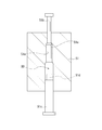
- a glow plug disclosed in Patent Document 1 is known. As shown in FIG. 11, the glow plug is disposed in the housing 90, a heater 91 having a cylindrical housing 90, a heat generating portion 91a fixed in the housing 90, and projecting from the tip of the housing 90, The rear end portion of the rod-like center shaft 92 protruding from the rear end of the housing 90, and the pin terminal 93 for fitting the rear end portion of the center shaft 92 to externally supply the heat generating portion 91a via the center shaft 92 Have.
- the heater 91 is a ceramic heater which is fitted in a conductive metal outer cylinder 94 fitted on the front end side of the housing 90 and causes the heat generating portion 91 a to project from the front ends of the housing 90 and the outer cylinder 94.
- the ceramic heater 91 includes a rod-like insulator 80 mainly composed of Si 3 N 4 , a U-shaped heating element 81 mainly composed of WC embedded at the tip end in the insulator 80, and one end Is connected to one end of the heat generating body 81, and the first lead wire 82 whose other end is exposed on a part of the outer peripheral surface of the insulator 80 and one end is connected to the other end of the heat generating body 81 And a second lead wire 83 whose other end is exposed to the other part of the surface.
- the other end of the first lead wire 82 is connected to the outer cylinder 94, the other end of the second lead wire 83 is connected to the energizing coil 95, and the energizing coil 95 is connected to the middle shaft 92.
- the tip side of the insulator 80 in which the heating element 81 is embedded is the heating portion 91 a of the ceramic heater 91.
- the pin terminal 93 has a small diameter portion 93a on the rear end side and a large diameter portion 93b on the front end side.
- the rear end side end face of the small diameter portion 93a has a curved shape.
- a first flange 93c is formed on the front end side of the large diameter portion 93b to be in contact with an insulator 96 made of an insulating material provided on the rear end side of the housing 90.
- a second flange 93d is formed on the rear end side of the large diameter portion 93b, and a locking convex portion 85a of a cap 97 for supplying power from the outside is engaged between the first flange 93c and the second flange 93d.
- a locking portion 93e to be stopped is formed.
- the male screw 90a of the housing 90 is screwed into the cylinder head of the diesel engine, whereby the heat generating portion 91a of the ceramic heater 91 is positioned in the combustion chamber of the diesel engine. Then, the housing 90 is grounded to the cylinder head, while the cap 97 connected to the battery is fitted to the pin terminal 93.
- the cap 97 includes a cup-shaped cap main body 85 and a conductive material 87 fixed in a state of being extended from the back side to the opening side by a fixing member 86 provided on the back side of the cap main body 85. At the opening side in the cap main body 85, a locking convex portion 85a which protrudes inward is formed.
- the conductive material 87 is connected to a lead 88 connected to the battery.
- the locking convex portion 85a of the cap main body 85 passes over the second flange 93d and engages with the locking portion 93e.
- the conductive material 87 abuts on the surface of the small diameter portion 93a.
- the ceramic heater 91 a voltage is applied between the housing 90, the outer cylinder 94 and the first lead wire 82, the pin terminal 93, the center shaft 92, the energizing coil 95 and the second lead wire 83.
- the heat generating portion 91a generates heat.
- the start of the diesel engine is started.
- the conventional pin terminal has the first flange at the front end of the large diameter portion and the second flange on the rear end side of the large diameter portion. For this reason, in this pin terminal, a portion to be crimped which is formed to have the same outer diameter and which can be crimped is limited between the first flange and the second flange and becomes short. For this reason, it is difficult to firmly connect the center shaft and the pin terminal in a short caulking portion, and by adopting a longer center shaft, it is necessary to secure the connection strength of these. For this reason, with this pin terminal, the reduction of the material has to be insufficient, and the weight reduction has also to be insufficient. And since the glow plug also adopts such a pin terminal and a longer center shaft, the reduction of materials can not but be insufficient, and the weight reduction can not but be inadequate. .
- the present invention has been made in view of the above situation, and provides a pin terminal that can be coupled with a central shaft with high bonding strength and can realize reduction and weight reduction of the material of the glow plug. It should be an issue to be done.
- the present invention is to solve the problem of providing a glow plug in which the center shaft and the pin terminal are joined with high bonding strength to exhibit excellent durability, and at the same time, material reduction and weight reduction can be realized. There is.
- the glow plug pin terminal according to the present invention has a shaft shape extending in the axial direction, and a small diameter portion to which a conductive material supplying power from the outside is connected; A flange integrally formed at the end of the small diameter portion, and having an outer diameter larger than that of the small diameter portion; The tip of the flange is integrally provided shorter in the axial direction than the small diameter portion, the outer diameter is larger than the small diameter portion, and the outer diameter is smaller than the flange, and the axial direction in the radial direction A cylindrical large-diameter portion having a fitting recess recessed from the front end to the rear end of the A glow plug pin terminal comprising: a locking portion located between a maximum diameter position of the flange and the large diameter portion, the outer diameter of which gradually decreases toward the large diameter portion, The large diameter portion has a caulking scheduled portion which can be formed to have the same outer diameter and can be caulked in a range from the tip end of the large diameter portion to the tip end of the locking portion.
- the first flange 93 c like the conventional pin terminal 93 is not formed. Therefore, with this pin terminal, while maintaining its entire length, that is, while maintaining compatibility with the cap fitted to the pin terminal, it is formed to have the same outer diameter, and the caulking scheduled portion The length is longer. For this reason, it becomes easy to couple
- the pin terminal 93 sufficiently presses the insulator 96 without increasing the contact area with the rear end of the insulator 96 by the first flange 93 c as in the prior art. It turned out that it is possible and the insulation effect by O ring can fully be exhibited. That is, there is no difference in the insulation performance between the glow plug provided with the pin terminal of the present invention and the conventional glow plug provided with the pin terminal 93 on which the first flange 93 c is formed.
- the glow plug pin terminal according to the present invention can be coupled to the central shaft with high bonding strength, and can realize reduction and weight reduction of the material of the glow plug. Therefore, by providing the pin terminal, the glow plug is inexpensive and exhibits excellent durability.
- the glow plug pin terminal of the present invention can be manufactured, for example, by subjecting a work made of a conductive metal to plastic working or cutting. Further, among the pin terminals, the small diameter portion, the flange, the large diameter portion, and the locking portion may be formed by plastic working, and the fitting recess may be formed by cutting. If the pin terminal is manufactured only by plastic working of a work made of a conductive metal, cutting chips of the work are not generated at the time of working, and it is preferable because reduction of manufacturing cost due to resource saving can be realized.
- caulking scheduled parts are formed to the same outer diameter does not mean that the outer diameter is strictly the same, and if caulking is possible, the outer diameter is not the same within a certain range substantially the same. Also in the case of Since the caulking process is a process performed on a cylindrical portion having a constant outer diameter, caulking can not be performed if a diameter difference corresponding to that of the conventional first flange 93c is formed. As a standard, if the difference is 0.2 mm or less, it can be regarded as the same outer diameter in the present invention.
- the tip end face of the large diameter portion is preferably smaller in diameter than the rear end face of the insulating member constituting the glow plug (claim 2). In this case, leakage from the pin terminal to the housing or the like can be prevented with high reliability.
- the fitting recess includes an inner peripheral surface extending from the front end to the rear end of the large diameter portion, and an upper bottom surface continuous with the rear end of the inner peripheral surface and positioned radially inside the locking portion or the flange.
- the rear end portion of the center shaft fitted in the fitting recess can be positioned rearward of the portion to be crimped.
- an upper bottom face refers to the area
- the upper bottom surface of the fitting recess formed in the work is likely to be distorted or the like under the influence of the plastic deformation.
- the wrinkles etc. which arose by distortion become easy to be formed in an upper base.
- plating is applied to the glow plug pin terminal from the viewpoint of surface protection and the like.
- the cleaning liquid or the like used in this plating process remains in the wrinkles or the like of the upper bottom surface, and the plating quality in the fitting recess tends to be deteriorated.
- rust or the like is easily generated on the upper bottom surface. Due to these, the quality of the pin terminal is easily deteriorated.
- the upper bottom surface has a tapered shape with a smaller diameter toward the rear end side (claim 4).
- the thickness around the upper bottom surface of the work becomes larger. Therefore, the upper bottom surface is less likely to be deformed even by plastic deformation when forming the flange, and distortion or the like does not easily occur on the upper bottom surface. For this reason, it becomes difficult for a washing
- the upper bottom surface be located on the tip side of the maximum diameter position of the flange (claim 5).
- the magnitude of the plastic deformation of the work when forming the flange by plastic deformation is largest at the position of the largest diameter of the flange. For this reason, it is possible to further reduce the influence of the above-mentioned plastic deformation on the upper bottom surface by locating the upper bottom surface of the fitting recess on the tip end side of the maximum diameter position of the flange. For this reason, the deformation of the top and bottom surfaces due to plastic deformation is less likely to occur, and the quality of the pin terminal becomes higher.
- the flange is connected to the first cylindrical surface, which is located on the small diameter portion side and has a diameter larger than the small diameter portion, and the first cylindrical surface, and the axial cross section forms an arc, and the cross section in the axial perpendicular direction Can have a circular convex surface and a cylindrical second cylindrical surface connected to the convex surface and having the same diameter as the first cylindrical surface. And it is preferable that a level
- the cap can be easily fitted to the pin terminal by the first cylindrical surface or the convex curved surface.
- the second cylindrical surface makes it difficult for the cap to come off the pin terminal.
- the cap can be suitably locked on the locking portion. For this reason, for example, even if the cap is detached from the locking portion due to vibration or the like and the cap is moved in the direction to be detached from the pin terminal, it is preferable that the cap is caught on the step and moved to the rear end side Will be prevented.
- step difference itself can also be functioned as a latching
- the above-mentioned flange is connected to the small diameter portion, and is connected to the first disk surface extending in a direction perpendicular to the axis and the first disk surface, and the taper is connected to the first cylindrical surface while the rear end is reduced in diameter. It is preferable to have a surface and a second disk surface extending in a direction perpendicular to the axis connecting the second cylindrical surface and the large diameter portion (Claim 7). In this case, the cap can be more easily fitted to the pin terminal by the first disk surface and the tapered surface. In addition, the second disc surface makes the cap more difficult to remove from the pin terminal.
- the glow plug of the present invention comprises a cylindrical housing, a heater fixed in the housing and having a heat generating portion projecting from the tip of the housing, and disposed in the housing, the rear end being the rear end of the housing
- the pin terminal has an axially extending axial shape, and a small diameter portion to which a conductive material supplying power from the outside is connected;
- a flange integrally formed at the end of the small diameter portion, and having an outer diameter larger than that of the small diameter portion;
- the tip of the flange is integrally provided shorter in the axial direction than the small diameter portion, the outer diameter is larger than the small diameter portion, and the outer diameter is smaller than the flange, and the axial direction in the radial direction
- a cylindrical large-diameter portion having a fitting
- the glow plug of the present invention comprises the pin terminal of the present invention. For this reason, in this glow plug, the center shaft and the pin terminal are joined with high bonding strength to exhibit excellent durability, and material reduction and weight reduction can be realized. For this reason, this glow plug is inexpensive and exhibits excellent durability.
- the caulking portion preferably has a length exceeding half of the axial length of the caulking portion.
- the bonding strength between the center shaft and the pin terminal is higher than in the case of a public article in which the caulking portion is half or less of the total axial length of the caulking portion, which exhibits excellent durability.
- the crimped portion be positioned on the tip side of the axial center of the portion to be crimped (claim 10).
- the pin terminal is crimped at a position close to the tip end of the large diameter portion. For this reason, in this glow plug, the load on the rear end portion of the center shaft can be reduced, and the durability of the glow plug is further improved.
- the fitting recess may be composed of an inner peripheral surface extending from the front end to the rear end of the large diameter portion, and an upper bottom surface continuous with the rear end of the inner peripheral surface and positioned radially inside the locking portion or flange.
- the upper bottom surface can be tapered so as to decrease in diameter toward the rear end.
- the center shaft may have a tapered rear end portion with a smaller diameter toward the rear end side. The rear end portion of the center shaft is preferably located in the upper bottom surface (claim 11).
- the rear end of the center shaft when the rear end side of the center shaft is tapered as described above, the rear end of the center shaft can be easily inserted into the fitting recess. Then, the rear end of the center shaft inserted into the fitting recess extends along the inner circumferential surface and reaches the upper bottom surface. At this time, by making the upper bottom surface into a tapered shape with a smaller diameter toward the rear end side, as described above, the upper bottom surface is less likely to be deformed even by plastic deformation, and distortion or the like hardly occurs on the upper bottom surface.
- the upper bottom surface refers to a range of a region including the surface to be the upper bottom in the fitting recess and the surface. For this reason, that the rear end portion of the center shaft is located in the upper bottom surface means that the center shaft with respect to the above surface is in a state in which the rear end portion of the center shaft is in contact The state in which the rear end portion of the is made close (see FIG. 10).
- the upper bottom surface be positioned on the tip side of the maximum diameter position of the flange (claim 12).
- the deformation of the upper and lower surfaces due to plastic deformation is less likely to occur, and it is possible to more preferably couple the center shaft and the pin terminal with high bonding strength.
- the depth of the fitting recess becomes relatively shallow, and the rear end of the center shaft can be shortened. For this reason, it becomes possible to form short the whole center axis
- the glow plug pin terminal of the present invention and the glow plug provided with this pin terminal can be coupled to the central shaft with high bonding strength, and can also realize reduction and weight reduction of the material of the glow plug. For this reason, the glow plug provided with this pin terminal exhibits low cost and excellent durability.
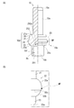
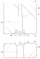
- FIG. 7 is a partially broken sectional view and a partially enlarged view showing a pin terminal before assembling according to the glow plug of the embodiment.
- (A) of FIG. 2 is a partially broken cross-sectional view showing the whole of the pin terminal, and (B) of FIG. 2 is a partially enlarged view showing a convex curved surface.
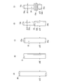
- FIG. 21 is a cross-sectional view showing a fourth step according to the manufacturing method of the embodiment. It is sectional drawing which shows the 1st type
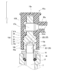
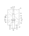
- the glow plug of the embodiment includes a metal shell 3 as a cylindrical housing, and a heater 5 fixed in the metal shell 3 and having a heat generating portion 5 a protruding from the end of the metal shell 3.
- the rear end portion of the metal shell 3 is disposed in the metal shell 3, and the rod-shaped middle shaft 7 protruding from the rear end of the metal shell 3 and the rear end portion of the middle shaft 7 are fitted to the heat generating portion 5a And a pin terminal 10 for conducting electricity.
- the heater 5 has a tubular shape extending in the axial direction with its distal end closed, and the heat generating tube 11 fixed to be conductive within the metallic shell 3 in a state where the distal end portion of the metallic shell 3 protrudes from its distal end side.
- the front end of the center shaft 7 is positioned in the heat generating tube 11, and the rear end of the center shaft 7 protrudes from the rear end of the metal shell 3.
- an insulating powder 12 containing MgO as a main component and a heat generating coil 13 are accommodated.
- the heat generating coil 13 has a front end joined to the front end side of the heat generating tube 11 and a rear end joined to the front end of the center shaft 7.
- the heater 5 is configured by the heating tube 11, the insulating powder 12 and the heating coil 13. Further, the tip end side of the heat generating tube 11 in which the heat generating coil 13 is housed together with the insulating powder 12 is the heat generating portion 5 a of the heater 5.
- An insulator 15 made of rubber packing is fixed to the central portion of the outer peripheral surface of the center shaft 7, and the opening end of the heat generating tube 11 is crimped around the insulator 15, whereby the heat generating tube 11 is fixed to the center shaft 7. In contrast, it is fixed in an insulated state.
- a large diameter hole 3b having the largest diameter among the shaft holes 3a is formed on the rear end side of the metal shell 3, and a stepped portion toward the rear end between the shaft hole 3a and the large diameter hole 3b is formed.
- An O-ring 17 and an annular insulator 19 made of an insulating material are placed.
- the inner shaft 7 is inserted through the inner circumference of each of the O-ring 17 and the insulator 19.
- the O-ring 17 and the insulator 19 correspond to an insulating member.
- the O-ring 17 and the insulator 19 may be integrally formed as the insulating member.
- an insulation member can also be comprised by the combination of three or more components, and an insulation member can also be comprised by a single component.
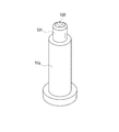
- the pin terminal 10 has the small diameter part 10a by the side of a back end, and the large diameter part 10b by the side of a tip, as shown to (A) of FIG.
- the small diameter portion 10a has an axially extending axial shape.
- a curved surface 10c is formed on the outer periphery of the rear end side end face of the small diameter portion 10a.
- a flange 10d is formed between the small diameter portion 10a and the large diameter portion 10b. From the flange 10d to the large diameter portion 10b, the pin terminal 10 has a shape that is gradually reduced in diameter. Further, the small diameter portion 10a and the large diameter portion 10b are separated by the flange 10d.
- the flange 10 d has a first cylindrical surface 21, a convex curved surface 22, and a second cylindrical surface 23.
- the first cylindrical surface 21 is in the form of a cylinder located on the small diameter portion 10a side and having a diameter larger than that of the small diameter portion 10a.
- the convex curved surface 22 is connected to the first cylindrical surface 21 and has an arc-shaped cross section in the axial direction and a circular cross-section in the direction perpendicular to the axis.
- the second cylindrical surface 23 is connected to the convex curved surface 22 and has a cylindrical shape having the same diameter as the first cylindrical surface 21.
- the flange 10d has a first disc surface 21a, a tapered surface 20, and a second disc surface 23a.
- the first disc surface 21a is connected to the small diameter portion 10a and extends in the direction perpendicular to the axis.
- the tapered surface 20 is connected to the first cylindrical surface 21 at the front end side, and connected to the first disc surface 21 a at the rear end side.
- the tapered surface 20 is formed to have a smaller diameter at the rear end side.
- the second disk surface 23a connects the second cylindrical surface 23 and the large diameter portion 10b, and extends in a direction perpendicular to the axis.
- the connecting portion between the second disk surface 23a and the large diameter portion 10b has an arc shape. Thus, the second disk surface 23a and the large diameter portion 10b are connected gently.
- the convex curved surface 22 is directed from the slightly tip side of the maximum diameter position MP toward the first cylindrical surface 21 with the slightly tip side of the maximum diameter position MP of the flange 10d as a boundary. It comprises a first arc 22 a and a second arc 22 b directed from the slightly tip side of the maximum diameter position MP to the second cylindrical surface 23. That is, the side having the first arc 22 a is the rear end side of the convex curved surface 22, and the side having the second arc 22 b is the front end side of the convex curved surface 22.
- a step 22c is formed on the boundary between the first arc 22a and the second arc 22b, that is, on the outer peripheral surface on the slightly tip side of the maximum diameter position MP of the convex curved surface 22.
- the second cylindrical surface 23 and the step 22c described above correspond to the locking portion 10e. The formation of the step 22c will be described in detail later.
- the locking portion 10e may be provided between the maximum diameter position MP of the flange 10d and the large diameter portion 10b, and as described above, the locking portion 10e is not limited to the second cylindrical surface 23 and the step 22c.
- the locking portion 10e may be formed by the step 22c, the second cylindrical surface 23, and the second disc surface 23a.
- any one of the step 22c, the second cylindrical surface 23 and the second disc surface 23a may be used as the locking portion 10e.
- the second cylindrical surface 23 and the second disk surface 23a may be combined to form the locking portion 10e.
- the large diameter part 10b is integrally provided in the front-end
- the range from the tip of the large diameter portion 10b to the tip of the locking portion 10e is formed with a diameter difference of 0.2 mm or less, and has substantially the same outer diameter. And this range is made into caulking planned part 10f.
- the fitting recessed part 25 by which the center shaft 7 is fitted is formed in the front end side end surface of the large diameter part 10b.
- the fitting recess 25 is continuous with the inner peripheral surface 251 extending from the front end to the rear end of the large diameter portion 10b and the rear end of the inner peripheral surface 251 inside the pin terminal 10, and the radial inside of the flange 10d.
- an upper bottom surface 252 located on the The upper bottom surface 252 is a range of area including the surface 252 a which becomes the upper bottom in the fitting recess 25 and the surface 252 a.
- the upper bottom surface 252 is tapered so as to decrease in diameter from the front end side to the rear end side of the pin terminal 10.
- the upper bottom surface 252 is positioned at the front end side of the maximum diameter position MP of the flange 10 d in the inside of the pin terminal 10, more specifically, at a position corresponding to the second cylindrical surface 23 in the inside of the pin terminal 10. doing.
- a cap 97 a is externally attached to the pin terminal 10.
- the cap 97 a has a cup-shaped cap main body 970 and a conductive material 87 a fixed to the back side of the cap main body 970.
- the cap body 970 is made of resin. Further, a locked portion 971 is formed inside the opening side of the cap body 970.
- the conductive material 87a is connected to a lead 88a connected to a battery (not shown).
- the pin terminal 10 is manufactured by the following steps.
- a steel rod 30 is prepared as a conductive metal having a circular cross section with ⁇ D ′.
- the bar 30 is cut in a direction perpendicular to the axis to obtain a first work 31 having a predetermined length as shown in FIG. 4 (B).
- an end face adjustment mold 50 having a cavity 50a is prepared.
- the inner diameter of the cavity 50a is ⁇ D, which is slightly larger than ⁇ D '. This ⁇ D is approximately the same diameter as the outer diameter of the large diameter portion 10b of the pin terminal 10 shown in FIG.
- a curved surface 50e is formed at the upper end of the cavity 50a.
- a kickout pin 50b is provided at the upper end of the cavity 50a, and a punch 50c is provided at the lower end of the cavity 50a so as to be capable of being pressed into the cavity 50a.
- a convex portion 50d of a first height is provided on the upper end surface of the punch 50c. The first height is a height corresponding to the first depth.
- the first work 31 is conveyed into the cavity 50a of the end face adjustment mold 50, and the first work 31 is pressed by the punch 50c.
- the rear end side end face of the first work 31 is press-contacted to the kickout pin 50b and the curved surface 50e to be plastically processed.
- the first work 31 is a second work 32 having a curved surface 32a at the end face on the rear end side. For this reason, even when the first work 31 is prepared, irregularities are produced on the rear end side end face, or even if the end face is inclined, the asperities are not enlarged by extrusion processing etc., and the obtained first 2
- the work 32 will not be deformed unintentionally.
- a first fitting recess 25a of a first depth is formed at the tip end surface of the second work 32 by the above-described convex portion 50d.
- a curved surface 51e is formed at the upper end of the cavity 51a. Further, a kickout pin 51b is provided at the upper end of the cavity 51a, and a punch 51c is provided at the lower end of the cavity 51a so as to be capable of being pressurized into the cavity 51a.
- the upper end surface of the punch 51c is provided with a convex portion 51d of a second height larger than the first height. The second height is a height corresponding to the second depth.
- the second work 32 is conveyed into the cavity 51 a of the extrusion die 51 so that the curved surface 32 a is upward, and the punch 51 c pressurizes the second work 32.
- the rear end side end face of the second workpiece 32 is pressure-welded again to the kickout pin 51b and the curved surface 51e, and is plastic-worked.
- the second work 32 is a third work 33 whose rear end side is reduced in diameter.
- the rear end side is a small diameter portion 33a of ⁇ d
- the front end side is a large diameter portion 33b of ⁇ D which is larger than ⁇ d.
- the end face of the small diameter portion 33a is a curved surface 10c which is a product shape by making the curved surface 32a small in diameter.
- a second fitting recess 25b of a second depth which is deeper than the first depth is formed by the convex portion 51d. Thereafter, the punch 51c is lowered, and the third work 33 is carried out of the extrusion die 51 by the kickout pin 51b.
- a flange forming mold 52 provided with a first mold 52a and a second mold 52b is prepared.
- the second die 52b is urged toward the first die 52a by a pressing spring 52f.
- a first cavity aligned with the first arc 22a in the tapered surface 20, the first cylindrical surface 21 and the convex curved surface 22 of the small diameter portion 10a and the flange 10d shown in FIG. 52c is formed. That is, the rear end side of the first circular arc 22a of the flange 10d can be formed by the first cavity 52c.
- the first cavity 52c is formed such that the upper end of the small diameter portion 33a is disposed in the first mold 52a when the third work 33 shown in (D) of FIG. 4 is disposed. Furthermore, a curved surface 52i is formed at the upper end of the first cavity 52c.
- the second mold 52b is provided with a second cavity 52e that matches the second cylindrical surface 23 of the flange 10d shown in FIG. 2, the second arc 22b of the convex curved surface 22, and the large diameter portion 10b. . That is, the tip end side can be formed from the second arc 22b of the flange 10d by the second cavity 52e.
- the first arc 22a and the second arc 22b in the pin terminal 10 are respectively formed at the end slightly beyond the maximum diameter position MP of the flange 10d (see FIG. 2 (B )reference). That is, as shown in FIG. 8, in the first mold 52a and the second mold 52b, the mold split surfaces 52j and 52k of the first cavity 52c and the second cavity 52e are located on the tip side of the maximum diameter position MP. .
- first round hole 521 which is aligned with the first arc 22a side.
- second round hole 522 aligned with the second arc 22b is formed.
- the maximum diameter N of the second round hole 522 is smaller than the maximum diameter M of the first round hole 521.
- a kickout pin 52d is provided at the upper end of the first cavity 52c.
- a punch 52g is provided at the lower end of the second cavity 52e so as to be capable of being pressurized into the second cavity 52e.
- the upper end surface of the punch 52g is provided with a convex portion 52h having a third height larger than the second height.
- the third height is a height corresponding to the third depth, and more specifically, a height from the tip end side of the third work 33 to a position corresponding to the second cylindrical surface 23 of the flange 10 d. is there.
- the convex portion 52 h has a tapered shape which decreases in diameter toward the upper end surface 520. Further, the upper end surface 520 of the convex portion 52h is knurled.
- the third work 33 is set so that the small diameter portion 33a is on the upper side, that is, the first die 52a side. Is conveyed, and the third work 33 is pressed by the punch 52g. Thus, the rear end side end face of the third work 33 is press-contacted to the kickout pin 52d and the curved surface 52i, and the third work 33 is plastically processed. Thus, the third work 33 is made the fourth work 34 as shown in (E) of FIG. 4.
- the rear end side of the fourth work 34 is the same small diameter portion 34 a as the small diameter portion 33 a of the third work 33. Further, a flange 10d is formed between the same large diameter portion 34b and the small diameter portion 34a as the large diameter portion 33b of the third work 33. At this time, the difference between the maximum diameter M of the first round hole 521 in the first cavity 52c and the maximum diameter N of the second round hole 522 in the second cavity 52e allows the flange 10d to be slightly distal to the maximum diameter position MP.
- a step 22c is formed on the outer peripheral surface. The step 22 c is shaped so as to be lowered toward the tip side of the convex curved surface 22 (the tip side of the fourth work 34).
- the end face of the small diameter portion 34a remains as the curved surface 10c.
- the third fitting recess 25c of the third depth which is deeper than the second depth is formed by the above-mentioned convex portion 52h.
- the small diameter portion 34a formed on the fourth work 34 corresponds to the small diameter portion 10a shown in FIG.
- the large diameter portion 34b formed on the fourth work 34 corresponds to the large diameter portion 10b shown in FIG. 2
- the third fitting recess 25c corresponds to the fitting recess 25 shown in FIG.
- an outer diameter finishing step of cutting with an unshown cutter or the like is performed on the outer periphery of the fourth work 34.
- an outer diameter finishing step of cutting with an unshown cutter or the like is performed on the outer periphery of the fourth work 34.
- the outer diameter finishing step can also be performed by polishing using a polishing machine or the like instead of cutting with a cutter or the like.
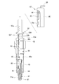
- the metal shell 3, the heat generating tube 11, the insulator 15, the heat generating coil 13, the center shaft 7, the O-ring 17, the insulator 19 and the like are prepared. Then, while electrically connecting these necessary portions, these and the pin terminal 10 are assembled by a known method. At this time, on the rear end side of the insulator 19, the caulking scheduled portion 10f (see FIG. 2A) of the pin terminal 10 is actually in a state where the rear end portion of the center shaft 7 is fitted in the fitting recess 25. Be tightened. As a result, as shown in FIGS. 1 and 10, the center shaft 7 and the pin terminal 10 are joined to complete the assembly.
- a crimped portion 10g is formed on the outer peripheral surface of the large diameter portion 10b, that is, the crimped portion 10f.
- the length ⁇ of the crimped portion 10g is, as shown in FIG. 10, greater than half of the axial total length ⁇ of the portion to be crimped 10f.
- caulking portion 10g is positioned such that caulking portion 10g is positioned on the tip side of the axial center of caulking portion 10f, that is, on the tip side of large diameter portion 10b of pin terminal 10. The position has been adjusted. Thus, the glow plug is completed.
- the male screw 3c of the metal shell 3 is screwed into the cylinder head of the diesel engine, whereby the heat generating portion 5a of the heater 5 is positioned in the combustion chamber of the diesel engine. Then, the metal shell 3 is grounded to the cylinder head, while the cap 97 a shown in FIG. 3 is fitted to the pin terminal 10.
- the heater 5 a voltage is applied between the metal shell 3 and the pin terminal 10 and the center shaft 7, and the heating coil 13 causes the heating portion 5 a to generate heat.
- the start of the diesel engine is started.
- the first flange 93c formed on the pin terminal 93 (see FIG. 8) in the conventional glow plug is not formed on the tip end portion of the pin terminal 10 included in the glow plug. Therefore, in this glow plug, as shown in FIGS. 1 and 10, the end face of the tip end of the pin terminal 10, ie, the end face of the tip end of the large diameter portion 10b abuts against the end face of the rear end of the insulator 19. There is. Thereby, the insulator 19 is pressed. Then, in this state, the insulator 19 presses the O-ring 17 at its tip end side.
- the O-ring 17 is elastically deformed in the axial hole 3a, and the O-ring 17 is in close contact with the wall surface of the center shaft 7, the insulator 19 and the axial hole 3a.
- the insulation effect between the center shaft 7 and the metal shell 3 by the O-ring 17 is sufficiently exhibited.
- the pin terminal 10 maintains its full length, that is, with the cap 97 fitted to the pin terminal 10.
- Length of caulking scheduled portion 10f formed to the same outer diameter and able to be caulked while maintaining compatibility (total axial length ⁇ of caulking scheduled portion 10f corresponding to straight portion of large diameter portion 10b) Is getting longer.
- the center shaft 7 and the pin terminal 10 can be easily firmly connected to each other by the long caulking portion 10f, and it is possible to adopt the shorter center shaft 7 with this glow plug.
- the glow plug provided with the pin terminal 10 realizes the reduction of the material and the weight reduction.
- the length ⁇ of the caulking portion 10g when actually caulking is a length exceeding half of the total axial length ⁇ of the caulking portion 10f. For this reason, in this glow plug, the bonding strength between the center shaft 7 and the pin terminal 10 is smaller than that of a public article (see FIG. 11) in which the length of the caulking portion is half or less of the total axial length of the caulking portion. It demonstrates high and reliable durability.
- the crimped portion 10g is positioned on the tip side of the center in the axial direction of the portion to be crimped 10f. For this reason, in this glow plug, caulking is performed on the pin terminal 10 at a position close to the tip end side of the large diameter portion 10 b. Therefore, in this glow plug, the load on the rear end portion of the center shaft 7 can be reduced, and the durability of the glow plug is further improved.
- the central shaft 7 and the pin terminal 10 are joined with high bonding strength to exhibit excellent durability, and material reduction and weight reduction can be realized.
- the tip end face of the large diameter portion 10b of the pin terminal 10 has a smaller diameter than the rear end face of the insulator 19 constituting the glow plug. For this reason, it is possible to prevent the electrical leakage from the pin terminal 10 to the metal shell 3 with high reliability.
- the fitting recess 25 has an inner circumferential surface 251 extending from the front end to the rear end of the large diameter portion 10b, and the inner circumference.
- An upper bottom surface 252 is formed continuously with the rear end of the surface 251 and located radially inward between the locking portion 10e and the flange 10d.
- the upper bottom surface 252 has a tapered shape with a smaller diameter toward the rear end, and the fitting recess 25 has the third depth, so the upper bottom surface 252 is a pin In the inside of the terminal 10, it is located in the location corresponded to the 2nd cylindrical surface 23.
- the thickness around the upper bottom surface 252 is large. Therefore, the upper bottom surface (corresponding to the upper bottom surface 252 of the fitting recess 25) of the third fitting recess 25c is not easily deformed even by plastic deformation when forming the flange 10d, and the upper bottom surface 252 is distorted or the like.
- the plastic deformation of the third work 33 is maximized at the maximum diameter position MP of the flange 10d, it is obtained because the upper bottom surface 252 is located on the tip side of the maximum diameter position MP of the flange 10d.
- the fourth work 34 deformation of the upper bottom surface 252 due to plastic deformation is more difficult to occur.
- the fourth work 34 distortion and wrinkles caused by the distortion are less likely to occur on the upper bottom surface 252, and cleaning fluid and the like during plating are less likely to remain on the upper bottom surface 252.
- plating in the fitting recess 25 is suitably performed. Further, in the pin terminal 10, rust and the like are less likely to occur on the upper bottom surface 252.
- the second fitting concave portion 25b is formed. It becomes difficult for the convex part 52h to slip, and it is possible to form the 3rd fitting recessed part 25c suitably. For these reasons, the quality of the pin terminal 10 is high, and the quality of the glow plug is high.
- the center shaft 7 has a tapered rear end portion which decreases in diameter toward the rear end side, and the rear end portion of the center shaft 7 is located in the upper bottom surface 252. Therefore, when the pin terminal 10 and the center shaft 7 are assembled, the rear end side of the center shaft 7 is tapered as described above, so that the rear end of the center shaft 7 can be easily inserted into the fitting recess 25. Then, the rear end of the center shaft 7 inserted into the fitting recess 25 reaches the upper bottom surface 252 along the inner peripheral surface 251. Thereby, with the rear end portion of the middle shaft 7 positioned in the upper bottom surface 252, it is possible to preferably couple the middle shaft 7 and the pin terminal 10 with high coupling strength. Therefore, the glow plug is highly durable.
- the depth of the fitting recess 25 is relatively shallow. It is possible to shorten the back end of the For this reason, in this glow plug, it is possible to form the entire center shaft 7 short, and it is possible to reduce the manufacturing cost of the glow plug. In this way, even if the depth of the fitting recess 25 is reduced and the rear end of the center shaft 7 is shortened, as shown in FIG. 10, the length ⁇ of the crimped portion 10g has a sufficient length. Because of this, the coupling strength between the center shaft 7 and the pin terminal 10 is kept high.
- the flange 10 d has a first cylindrical surface 21, a convex curved surface 22, and a second cylindrical surface 23. Furthermore, the flange 10d connects the first disk surface 21a, the tapered surface 20 connected to the first disk surface 21a and the first cylindrical surface 21, the second cylindrical surface 23 and the large diameter portion 10b. And a second disk surface 23a. Further, on the outer peripheral surface of the convex curved surface 22 of the flange 10d, a step 22c is formed slightly on the tip end side of the maximum diameter position MP.
- the cap 97a can be easily fitted to the pin terminal 10, and the cap 97a locked to the locking portion 10e is difficult to remove from the pin terminal 10.
- the locked portion 971 of the cap main body 970 has the first disc surface 21a and the tapered surface. It elastically deforms so as to expand along 20 and reaches the convex curved surface 22. Then, the locked portion 971 is elastically deformed so as to further spread along the first arc 22a, and reaches the maximum diameter position MP.
- the engaged portion 971 After passing through the maximum diameter position MP, along the step 22c and the second circular arc 22b, the engaged portion 971 is elastically deformed so as to narrow, and reaches the engaging portion 10e. Then, the locked portion 971 is locked to the second cylindrical surface 23. As described above, since the mounting direction of the cap 97a with respect to the pin terminal 10 and the tapered surface 20 and the first arc 22a are in line with each other, the cap 97a can be easily fitted to the pin terminal 10. .
- the locked portion 971 is disengaged from the second cylindrical surface 23 due to the vibration of the diesel engine and the cap 97a is removed from the pin terminal 10, ie, in the direction opposite to the arrow in FIG.
- the portion 971 is caught on the above-mentioned step 22c and is locked to the step 22c as it is. Therefore, for example, even if the locking by the second cylindrical surface 23 is released and the locked portion 971 is elastically deformed so as to expand along the second arc 22b, the locked portion 971 is in contact with the step 22c. It will be in contact with you. For this reason, the engaged portion 971 can not spread larger than the second arc 22b, and can not reach the first arc 22a side beyond the step 22c.
- the locked portion 971 is locked to the step 22c.
- the cap 97a since the cap 97a is double-locked by the second cylindrical surface 23 and the step 22c, the cap 97a can be fitted to the pin terminal 10 more preferably. It has become.
- the step 22c is formed by utilizing the difference between the maximum diameter M of the first round hole 521 in the first cavity 52c and the maximum diameter N of the second round hole 522 in the second cavity 52e. doing. Therefore, for example, generation of cutting chips of the fourth work 34 can be suppressed as compared with the case where the step 22c is formed by cutting the entire outer peripheral surface of the convex curved surface 22.
- the glow plug it is possible to use a resin housing instead of the metal shell 3.
- the heat generating tube 11, the insulating powder 12, and the heat generating coil 13 are used as the heater 5 in the said Example, it is also possible to use a ceramic heater as a heater.
- the locking portion 10e may be configured by the step 22, the second cylindrical surface 23, and the second disk surface 23a, and the locked portion 971 may be locked by these.
- the locked portion 971 becomes more difficult to remove from the locking portion 10e, and the cap 97a becomes more difficult to remove from the pin terminal 10e.
- the punches 50c and 51c can also have the same configuration as the punch 52g except for the lengths of the convex portions 50d and 51d.
- the first and second works 31 and 32 can be formed.
- the convex portions 50d, 51d do not slip easily, and the first fitting recess 25a and the second fitting recess 25b can be suitably formed.
- the step 22 c may not be formed by plastic working in the fourth step, but may be formed by cutting with a cutter in the outer shape finishing step for the fourth work 34.
- the present invention is applicable to glow plugs.
Landscapes
- Engineering & Computer Science (AREA)
- Chemical & Material Sciences (AREA)
- Combustion & Propulsion (AREA)
- Mechanical Engineering (AREA)
- General Engineering & Computer Science (AREA)
- Manufacturing & Machinery (AREA)
- Resistance Heating (AREA)
Abstract
Description
該小径部の先端に一体に設けられ、該小径部よりも外径が大きく形成されたフランジと、
該フランジの先端で前記小径部よりも前記軸方向に短く一体に設けられ、該小径部よりも外径が大きく、前記フランジよりも外径が小さく形成され、自身の径方向内部に前記軸方向の先端から後端へ向けて凹設された嵌合凹部を有する円筒状の大径部と、
前記フランジの最大径位置と前記大径部との間に位置し、自身の外径が該大径部へ向けて漸次縮径する係止部とを備えるグロープラグ用ピン端子であって、
前記大径部は、自身の先端から前記係止部の先端までの範囲において、同一外径に形成されて加締め可能な加締め予定部を有していることを特徴とする(請求項1)。
前記ピン端子は、軸方向に延びる軸状をなし、外部から電力を供給する導電材が接続される小径部と、
該小径部の先端に一体に設けられ、該小径部よりも外径が大きく形成されたフランジと、
該フランジの先端で前記小径部よりも前記軸方向に短く一体に設けられ、該小径部よりも外径が大きく、前記フランジよりも外径が小さく形成され、自身の径方向内部に前記軸方向の先端から後端へ向けて凹設された嵌合凹部を有する円筒状の大径部と、
前記フランジの最大径位置と前記大径部との間に位置し、自身の外径が該大径部へ向けて漸次縮径する係止部とを備え、
前記大径部は、自身の先端から前記係止部の先端までの範囲において、同一外径に形成されて加締め可能な加締め予定部を有し、
該加締め予定部の一部が前記中軸の前記後端部を加締め固定する加締め部とされていることを特徴とする(請求項8)。
まず、図4の(A)に示すように、φD’で断面が円形の導電金属としての鋼材製の棒材30を用意する。この棒材30を軸直角方向で切断し、図4の(B)に示すように、所定の長さの第1ワーク31を得る。
図5に示すように、キャビティ50aをもつ端面調整金型50が用意されている。このキャビティ50aの内径は、φDとされており、φD’よりもやや大きくされている。このφDは、図2に示すピン端子10における大径部10bの外径とほぼ同径である。
次いで、図6に示すように、上方が小径に形成されたキャビティ51aをもつ押出金型51が用意されている。
この第4工程では、図7に示すように、第1型52a及び第2型52bを備えたフランジ成形金型52が用意される。この第2型52bは押圧ばね52fにより第1型52aに向かって付勢されている。
この後、第4ワーク34の外周について、図示しないカッタ等により切削を行う外径仕上げ工程を行う。これにより、例えば、フランジ10dの外周をカットすることで、第4ワーク34のフランジ10dの外周側の真円度が高められる。この外径仕上げ工程を経て、図2に示すピン端子10が製造される。なお、カッタ等による切削に替えて、研磨機等を用いた研磨を行うことにより、外径仕上げ工程を行うこともできる。
10a…小径部
10d…フランジ
25…嵌合凹部
10b…大径部
MP…最大径位置
10e…係止部
10…ピン端子
10f…加締め予定部
19…インシュレータ(絶縁部材)
251…内周面
252…上底面
3…主体金具(ハウジング)
5a…発熱部
5…ヒータ
7…中軸
17…Oリング
10g…加締め部
251…内周面
252…上底面
21…第1円筒面
22…凸曲面
23…第2円筒面
22c…段差
21a…第1円板面
20…テーパ面
23a…第2円板面
Claims (12)
- 軸方向に延びる軸状をなし、外部から電力を供給する導電材が接続される小径部と、
該小径部の先端に一体に設けられ、該小径部よりも外径が大きく形成されたフランジと、
該フランジの先端で前記小径部よりも前記軸方向に短く一体に設けられ、該小径部よりも外径が大きく、前記フランジよりも外径が小さく形成され、自身の径方向内部に前記軸方向の先端から後端へ向けて凹設された嵌合凹部を有する円筒状の大径部と、
前記フランジの最大径位置と前記大径部との間に位置し、自身の外径が該大径部へ向けて漸次縮径する係止部とを備えるグロープラグ用ピン端子であって、
前記大径部は、自身の先端から前記係止部の先端までの範囲において、同一外径に形成されて加締め可能な加締め予定部を有していることを特徴とするグロープラグ用ピン端子。 - 前記大径部の先端面は、グロープラグを構成する絶縁部材の後端面よりも小径である請求項1記載のグロープラグ用ピン端子。
- 前記嵌合凹部は、前記大径部の先端から後端に向けて延びる内周面と、該内周面の後端と連続し、前記係止部又は前記フランジの径方向内部に位置する上底面とからなる請求項1又は2記載のグロープラグ用ピン端子。
- 前記上底面は後端側に向かって小径となるテーパ状をなしている請求項3記載のグロープラグ用ピン端子。
- 前記上底面は、前記フランジの前記最大径位置よりも前記先端側に位置している請求項4記載のグロープラグ用ピン端子。
- 前記フランジは、前記小径部側に位置して該小径部より大径をなす円筒状の第1円筒面と、該第1円筒面と接続され、軸方向の断面が円弧をなし、軸直角方向の断面が円形をなす凸曲面と、該凸曲面と接続され、該第1円筒面と同径をなす円筒状の第2円筒面とを有し、
前記凸曲面には、前記最大径位置よりも前記第2円筒面側となる位置に、段差が形成されている請求項1乃至4のいずれか1項記載のグロープラグ用ピン端子。 - 前記フランジは、前記小径部側に位置して該小径部より大径をなす円筒状の第1円筒面と、該第1円筒面と接続され、軸方向の断面が円弧をなし、軸直角方向の断面が円形をなす凸曲面と、該凸曲面と接続され、該第1円筒面と同径をなす円筒状の第2円筒面とを有している請求項6記載のグロープラグ用ピン端子。
- 筒状のハウジングと、該ハウジング内に固定され、該ハウジングの先端から突出する発熱部を有するヒータと、該ハウジング内に配置され、後端部が該ハウジングの後端から突出する棒状の中軸と、該ハウジングの後端で該中軸を挿通する絶縁部材と、該中軸の該後端部に嵌合し、該中軸を介して該発熱部に外部から通電を行うためのピン端子とを備えたグロープラグにおいて、
前記ピン端子は、軸方向に延びる軸状をなし、外部から電力を供給する導電材が接続される小径部と、
該小径部の先端に一体に設けられ、該小径部よりも外径が大きく形成されたフランジと、
該フランジの先端で前記小径部よりも前記軸方向に短く一体に設けられ、該小径部よりも外径が大きく、前記フランジよりも外径が小さく形成され、自身の径方向内部に前記軸方向の先端から後端へ向けて凹設された嵌合凹部を有する円筒状の大径部と、
前記フランジの最大径位置と前記大径部との間に位置し、自身の外径が該大径部へ向けて漸次縮径する係止部とを備え、
前記大径部は、自身の先端から前記係止部の先端までの範囲において、同一外径に形成されて加締め可能な加締め予定部を有し、
該加締め予定部の一部が前記中軸の前記後端部を加締め固定する加締め部とされていることを特徴とするグロープラグ。 - 前記加締め部は、前記加締め予定部の前記軸方向の全長の半分を超える長さを有している請求項8記載のグロープラグ。
- 前記加締め部は、前記加締め予定部における前記軸方向の中心よりも先端側に位置している請求項9記載のグロープラグ。
- 前記嵌合凹部は、前記大径部の先端から後端に向けて延びる内周面と、該内周面の後端と連続し、前記係止部又は前記フランジの径方向内部に位置する上底面とからなり、
前記上底面は後端側に向かって小径となるテーパ状をなし、
前記中軸は後端側に向かって小径となるテーパ状の後端部を有し、
該上底面内に該中軸の該後端部が位置している請求項8乃至10のいずれか1項記載のグロープラグ。 - 前記上底面は、前記フランジの前記最大径位置よりも前記先端側に位置している請求項10記載のグロープラグ。
Priority Applications (4)
| Application Number | Priority Date | Filing Date | Title |
|---|---|---|---|
| US13/876,523 US9385496B2 (en) | 2010-10-05 | 2011-08-17 | Glow plug terminal and glow plug |
| EP11830444.3A EP2626631B1 (en) | 2010-10-05 | 2011-08-17 | Glow plug terminal and glow plug |
| JP2012506258A JP5426755B2 (ja) | 2010-10-05 | 2011-08-17 | グロープラグ用ピン端子及びグロープラグ |
| KR1020137008843A KR101502254B1 (ko) | 2010-10-05 | 2011-08-17 | 글로 플러그용 핀 단자 및 글로 플러그 |
Applications Claiming Priority (4)
| Application Number | Priority Date | Filing Date | Title |
|---|---|---|---|
| JP2010225595 | 2010-10-05 | ||
| JP2010225599 | 2010-10-05 | ||
| JP2010-225599 | 2010-10-05 | ||
| JP2010-225595 | 2010-10-05 |
Publications (1)
| Publication Number | Publication Date |
|---|---|
| WO2012046511A1 true WO2012046511A1 (ja) | 2012-04-12 |
Family
ID=45927509
Family Applications (2)
| Application Number | Title | Priority Date | Filing Date |
|---|---|---|---|
| PCT/JP2011/068628 Ceased WO2012046510A1 (ja) | 2010-10-05 | 2011-08-17 | グロープラグ用ピン端子の製造方法及びグロープラグの製造方法 |
| PCT/JP2011/068629 Ceased WO2012046511A1 (ja) | 2010-10-05 | 2011-08-17 | グロープラグ用ピン端子及びグロープラグ |
Family Applications Before (1)
| Application Number | Title | Priority Date | Filing Date |
|---|---|---|---|
| PCT/JP2011/068628 Ceased WO2012046510A1 (ja) | 2010-10-05 | 2011-08-17 | グロープラグ用ピン端子の製造方法及びグロープラグの製造方法 |
Country Status (5)
| Country | Link |
|---|---|
| US (2) | US9236700B2 (ja) |
| EP (2) | EP2626630B1 (ja) |
| JP (2) | JP5426755B2 (ja) |
| KR (2) | KR101460924B1 (ja) |
| WO (2) | WO2012046510A1 (ja) |
Families Citing this family (4)
| Publication number | Priority date | Publication date | Assignee | Title |
|---|---|---|---|---|
| EP2626630B1 (en) * | 2010-10-05 | 2019-06-26 | NGK Spark Plug Co., Ltd. | Method for producing glow plug terminals, and method for producing glow plugs |
| CA2811666C (en) * | 2012-04-05 | 2021-06-29 | Shell Internationale Research Maatschappij B.V. | Compaction of electrical insulation for joining insulated conductors |
| JP6370663B2 (ja) * | 2014-10-09 | 2018-08-08 | 日本特殊陶業株式会社 | グロープラグ |
| DE102016108592B4 (de) * | 2016-05-10 | 2018-06-28 | Borgwarner Ludwigsburg Gmbh | Glühkerze und Verfahren zum Herstellen einer Glühkerze |
Citations (3)
| Publication number | Priority date | Publication date | Assignee | Title |
|---|---|---|---|---|
| JP2002260827A (ja) | 2001-03-02 | 2002-09-13 | Ngk Spark Plug Co Ltd | ヒータ及びその製造方法 |
| JP2005308295A (ja) * | 2004-04-21 | 2005-11-04 | Ngk Spark Plug Co Ltd | グロープラグ用ピン端子の製造方法及びグロープラグの製造方法 |
| JP2009041837A (ja) * | 2007-08-08 | 2009-02-26 | Ngk Spark Plug Co Ltd | グロープラグ |
Family Cites Families (25)
| Publication number | Priority date | Publication date | Assignee | Title |
|---|---|---|---|---|
| US4312120A (en) * | 1980-05-22 | 1982-01-26 | Bendix Autolite Corporation | Glow plug manufacture |
| US4491112A (en) * | 1982-01-13 | 1985-01-01 | Nissan Motor Company, Limited | Failsafe for an engine control |
| JPS60114629A (ja) * | 1983-11-28 | 1985-06-21 | Jidosha Kiki Co Ltd | デイ−ゼルエンジン用グロ−プラグ |
| DE3701929A1 (de) * | 1986-01-22 | 1987-08-13 | Jidosha Kiki Co | Gluehkerze fuer eine dieselmaschine |
| JPS62148869U (ja) * | 1986-03-11 | 1987-09-19 | ||
| JPS6361662U (ja) * | 1986-10-09 | 1988-04-23 | ||
| JPH01313362A (ja) * | 1988-06-09 | 1989-12-18 | Ngk Spark Plug Co Ltd | セラミック発熱体およびその製造方法 |
| CH681186A5 (ja) * | 1989-11-09 | 1993-01-29 | Battelle Memorial Institute | |
| JPH04143518A (ja) * | 1990-10-04 | 1992-05-18 | Ngk Spark Plug Co Ltd | 自己制御型セラミックグロープラグ |
| DE4335292A1 (de) * | 1993-10-15 | 1995-04-20 | Beru Werk Ruprecht Gmbh Co A | Glühkerze |
| WO1999005455A1 (en) * | 1997-07-25 | 1999-02-04 | Arlton Paul E | Glow plug connection for model engines |
| DE19852785A1 (de) * | 1998-09-28 | 2000-03-30 | Bosch Gmbh Robert | Keramische Glühstiftkerze |
| JP4313464B2 (ja) * | 1999-04-30 | 2009-08-12 | 本田技研工業株式会社 | 燃料改質装置 |
| JP3823003B2 (ja) * | 2000-02-28 | 2006-09-20 | 日本特殊陶業株式会社 | シーズ型グロープラグ及びその製造方法 |
| DE60228021D1 (de) * | 2001-05-28 | 2008-09-18 | Ngk Spark Plug Co | Heizung und Glühkerze |
| JP2002359060A (ja) * | 2001-05-31 | 2002-12-13 | Ngk Spark Plug Co Ltd | ヒータ、及びヒータの製造方法 |
| JP2003059624A (ja) * | 2001-08-10 | 2003-02-28 | Ngk Spark Plug Co Ltd | ヒータ |
| DE10248802A1 (de) * | 2002-10-19 | 2004-04-29 | Robert Bosch Gmbh | Glühstiftkerze mit stark verkürzter Regelwendel |
| US6696670B1 (en) * | 2002-12-03 | 2004-02-24 | O'donnell Steven B. | Glow plug with tightly-fit electrode |
| JP2006250459A (ja) * | 2005-03-11 | 2006-09-21 | Ngk Spark Plug Co Ltd | グロープラグ用ピン端子 |
| US7607206B2 (en) * | 2005-12-29 | 2009-10-27 | Federal Mogul World Wide, Inc. | Method for forming layered heating element for glow plug |
| US7329836B2 (en) * | 2006-03-30 | 2008-02-12 | Ngk Spark Plug Co., Ltd. | Glow plug with O-ring seal |
| US7572480B2 (en) * | 2006-10-19 | 2009-08-11 | Federal-Mogul World Wide, Inc. | Method of fabricating a multilayer ceramic heating element |
| DE102007031401A1 (de) * | 2007-07-05 | 2009-01-08 | Hirschmann Automotive Gmbh | Steckverbinder, augebildet zur Kontaktierung mit einer Glühkerze, bei dem ein Lamellenkontakt über einen Vorsprung verprägt ist |
| EP2626630B1 (en) * | 2010-10-05 | 2019-06-26 | NGK Spark Plug Co., Ltd. | Method for producing glow plug terminals, and method for producing glow plugs |
-
2011
- 2011-08-17 EP EP11830443.5A patent/EP2626630B1/en not_active Not-in-force
- 2011-08-17 KR KR1020137008842A patent/KR101460924B1/ko not_active Expired - Fee Related
- 2011-08-17 US US13/876,191 patent/US9236700B2/en not_active Expired - Fee Related
- 2011-08-17 EP EP11830444.3A patent/EP2626631B1/en active Active
- 2011-08-17 JP JP2012506258A patent/JP5426755B2/ja active Active
- 2011-08-17 WO PCT/JP2011/068628 patent/WO2012046510A1/ja not_active Ceased
- 2011-08-17 JP JP2011553203A patent/JP5438134B2/ja not_active Expired - Fee Related
- 2011-08-17 KR KR1020137008843A patent/KR101502254B1/ko not_active Expired - Fee Related
- 2011-08-17 US US13/876,523 patent/US9385496B2/en not_active Expired - Fee Related
- 2011-08-17 WO PCT/JP2011/068629 patent/WO2012046511A1/ja not_active Ceased
Patent Citations (3)
| Publication number | Priority date | Publication date | Assignee | Title |
|---|---|---|---|---|
| JP2002260827A (ja) | 2001-03-02 | 2002-09-13 | Ngk Spark Plug Co Ltd | ヒータ及びその製造方法 |
| JP2005308295A (ja) * | 2004-04-21 | 2005-11-04 | Ngk Spark Plug Co Ltd | グロープラグ用ピン端子の製造方法及びグロープラグの製造方法 |
| JP2009041837A (ja) * | 2007-08-08 | 2009-02-26 | Ngk Spark Plug Co Ltd | グロープラグ |
Also Published As
| Publication number | Publication date |
|---|---|
| US20130199037A1 (en) | 2013-08-08 |
| KR20130071482A (ko) | 2013-06-28 |
| EP2626630A4 (en) | 2017-12-06 |
| KR20130096273A (ko) | 2013-08-29 |
| WO2012046510A1 (ja) | 2012-04-12 |
| JPWO2012046511A1 (ja) | 2014-02-24 |
| US9385496B2 (en) | 2016-07-05 |
| JP5426755B2 (ja) | 2014-02-26 |
| EP2626631A4 (en) | 2017-12-06 |
| JP5438134B2 (ja) | 2014-03-12 |
| KR101502254B1 (ko) | 2015-03-12 |
| EP2626631A1 (en) | 2013-08-14 |
| KR101460924B1 (ko) | 2014-11-13 |
| US20130180975A1 (en) | 2013-07-18 |
| JPWO2012046510A1 (ja) | 2014-02-24 |
| EP2626630A1 (en) | 2013-08-14 |
| EP2626630B1 (en) | 2019-06-26 |
| EP2626631B1 (en) | 2019-05-08 |
| US9236700B2 (en) | 2016-01-12 |
Similar Documents
| Publication | Publication Date | Title |
|---|---|---|
| JP4960118B2 (ja) | グロープラグ | |
| CN101205865B (zh) | 电热塞及其制造方法 | |
| CN103608977A (zh) | 针形端子 | |
| WO2012046511A1 (ja) | グロープラグ用ピン端子及びグロープラグ | |
| JP4623645B2 (ja) | グロープラグ | |
| JP2013125587A (ja) | スパークプラグの製造方法 | |
| JP2012154552A (ja) | グロープラグおよびその製造方法 | |
| US7115836B2 (en) | Glow plug | |
| JP2007032877A (ja) | グロープラグおよびその製造方法 | |
| JP5351236B2 (ja) | グロープラグ | |
| WO2012102109A1 (ja) | グロープラグ | |
| JP4241489B2 (ja) | グロープラグ用ピン端子の製造方法及びグロープラグの製造方法 | |
| JP4890901B2 (ja) | グロープラグおよびその製造方法 | |
| JP4295164B2 (ja) | グロープラグ | |
| JP2009074708A (ja) | グロープラグの製造方法 | |
| JP5639227B2 (ja) | グロープラグ | |
| JP6203561B2 (ja) | ヒータユニットおよびそれを備えたグロープラグ | |
| JP2006153338A (ja) | グロープラグ | |
| JP4478626B2 (ja) | グロープラグおよびその製造方法 | |
| JP2014092318A (ja) | グロープラグ及びグロープラグの製造方法 | |
| JP2013224805A (ja) | グロープラグ、及び、その製造方法 |
Legal Events
| Date | Code | Title | Description |
|---|---|---|---|
| WWE | Wipo information: entry into national phase |
Ref document number: 2012506258 Country of ref document: JP |
|
| 121 | Ep: the epo has been informed by wipo that ep was designated in this application |
Ref document number: 11830444 Country of ref document: EP Kind code of ref document: A1 |
|
| WWE | Wipo information: entry into national phase |
Ref document number: 13876523 Country of ref document: US |
|
| ENP | Entry into the national phase |
Ref document number: 20137008843 Country of ref document: KR Kind code of ref document: A |
|
| NENP | Non-entry into the national phase |
Ref country code: DE |
|
| WWE | Wipo information: entry into national phase |
Ref document number: 2011830444 Country of ref document: EP |