WO2012049879A1 - Appareil dentaire et son procédé de fabrication - Google Patents
Appareil dentaire et son procédé de fabrication Download PDFInfo
- Publication number
- WO2012049879A1 WO2012049879A1 PCT/JP2011/062388 JP2011062388W WO2012049879A1 WO 2012049879 A1 WO2012049879 A1 WO 2012049879A1 JP 2011062388 W JP2011062388 W JP 2011062388W WO 2012049879 A1 WO2012049879 A1 WO 2012049879A1
- Authority
- WO
- WIPO (PCT)
- Prior art keywords
- denture
- bridge
- partial
- natural tooth
- resin
- Prior art date
- Legal status (The legal status is an assumption and is not a legal conclusion. Google has not performed a legal analysis and makes no representation as to the accuracy of the status listed.)
- Ceased
Links
Images
















Classifications
-
- A—HUMAN NECESSITIES
- A61—MEDICAL OR VETERINARY SCIENCE; HYGIENE
- A61C—DENTISTRY; APPARATUS OR METHODS FOR ORAL OR DENTAL HYGIENE
- A61C13/00—Dental prostheses; Making same
- A61C13/225—Fastening prostheses in the mouth
- A61C13/267—Clasp fastening
-
- A—HUMAN NECESSITIES
- A61—MEDICAL OR VETERINARY SCIENCE; HYGIENE
- A61C—DENTISTRY; APPARATUS OR METHODS FOR ORAL OR DENTAL HYGIENE
- A61C13/00—Dental prostheses; Making same
- A61C13/0003—Making bridge-work, inlays, implants or the like
- A61C13/0006—Production methods
-
- A—HUMAN NECESSITIES
- A61—MEDICAL OR VETERINARY SCIENCE; HYGIENE
- A61C—DENTISTRY; APPARATUS OR METHODS FOR ORAL OR DENTAL HYGIENE
- A61C13/00—Dental prostheses; Making same
- A61C13/08—Artificial teeth; Making same
- A61C13/087—Artificial resin teeth
-
- A—HUMAN NECESSITIES
- A61—MEDICAL OR VETERINARY SCIENCE; HYGIENE
- A61C—DENTISTRY; APPARATUS OR METHODS FOR ORAL OR DENTAL HYGIENE
- A61C13/00—Dental prostheses; Making same
- A61C13/225—Fastening prostheses in the mouth
-
- A—HUMAN NECESSITIES
- A61—MEDICAL OR VETERINARY SCIENCE; HYGIENE
- A61C—DENTISTRY; APPARATUS OR METHODS FOR ORAL OR DENTAL HYGIENE
- A61C13/00—Dental prostheses; Making same
- A61C13/225—Fastening prostheses in the mouth
- A61C13/26—Dentures without palates; Partial dentures, e.g. bridges
Definitions
- the present invention relates to a partial denture mounted in the oral cavity and a method for manufacturing the same.
- FIG. 7 of Patent Document 1 also discloses an invention in which bag-shaped bridge portions are formed at both ends of the denture.
- this bridge portion has a bag-like shape that opens downward and is expected to cover the remaining natural teeth from above, but it fits from above if there is no significant gap between the adjacent remaining natural teeth. I can't.
- An object of the present invention is to provide a partial denture that can reliably maintain a fixed state while having the same appearance requirements as a remaining natural tooth.
- a partial denture according to the present invention includes a solid denture part that fills a missing natural tooth part, and extends integrally from the denture part to both sides or one side of the denture part.
- a bridge part that removably engages with the outer peripheral surface to fix the denture part, and the denture part and the bridge part are made of a resin mainly composed of polypropylene or polyethylene colored in a color corresponding to a natural tooth color. It is characterized by having an integrally molded structure.
- a solid denture portion that fills the natural tooth missing portion, and integrally extending from the denture portion toward the remaining natural teeth located on both sides of the denture portion, the outer peripheral surfaces of the remaining natural teeth on both sides
- a bridge portion that detachably engages with the remaining natural teeth so as to be sandwiched from inside and outside in an elastically deformed state and fixes the denture portion, and the denture portion and the bridge portion are colored in a color corresponding to the natural tooth color It is characterized by having a structure integrally formed with a resin mainly composed of polypropylene or polyethylene.
- mainly composed of polypropylene or polyethylene means that polypropylene or polyethylene is contained by 70% or more by weight, and the ratio may be 100%.
- the bridge part can be elastically deformed compared to a conventional partial denture to which a metal bridge part is attached. Yes, it can be mounted more reliably corresponding to the shape of the adjacent remaining natural tooth.
- the user since it is an integrated partial denture, the user is not aware of the boundary between the denture part and the bridge part, and feels uncomfortable at the time of wearing.
- the denture part and the bridge part are colored in a color corresponding to the natural tooth color, it is difficult to discriminate that it is a partial denture at the time of wearing, and the aesthetics are enhanced.
- the bridge portion protrudes in a C shape from the denture portion to both sides thereof in a plan view and can be elastically deformed in the expanding / reducing direction.
- the bridge portion is C-shaped in a plan view, it can be attached and detached even if there is little gap between adjacent natural teeth. Further, the denture portion can be fixed by sandwiching the outer peripheral surface of the remaining natural tooth more securely by elastically deforming in the expanding / reducing direction.
- the upper end position of the bridge portion in front view is substantially the same height as the upper end position of the denture portion, and the lower end position of the bridge portion is higher than the lower end position of the denture portion.
- the dimension in the height direction is smaller than the dimension in the height direction of the denture part.
- the denture part easily fits in the missing natural tooth part, and the bridge part easily engages with the remaining natural tooth.
- the bridge portion has a curved portion that covers the upper peripheral edge of the remaining natural tooth while exposing the upper surface of the remaining natural tooth in a state of being engaged with the remaining natural tooth.
- the denture part and the bridge part may be integrally formed of the same component resin mainly composed of polypropylene or polyethylene colored in a color corresponding to a natural tooth color.
- the denture part and the bridge part can be manufactured by a simple method by integrally molding with a resin of the same component mainly composed of polypropylene or polyethylene having excellent strength, and the oral cavity can be reliably produced with sufficient strength.
- a partial denture fixed inside can be realized.
- the resin which comprises the said denture part has a mixing
- the blending weight ratio of polyethylene may be large.
- the denture part increases the blending ratio of acrylic with excellent aesthetics
- the bridge part increases the blending ratio of polypropylene or polyethylene with excellent strength, so that a partial denture that achieves both aesthetics and strength can be obtained. realizable.
- Such partial dentures are particularly effective for anterior teeth where aesthetics are important.
- a resin mainly comprising polypropylene or polyethylene having a gingival part formed at an end on the gingival side in the denture part, wherein the denture part and the bridge part are colored in a color corresponding to a natural tooth color.
- the gingiva part is formed integrally with the denture part with a resin mainly composed of polypropylene or polyethylene colored in natural gingival color.
- the end part of the denture part is made to resemble natural gingiva. Since a colored gingival part is formed, it is suitable for patients whose gums have declined. Furthermore, since the gingival part is also formed of a resin mainly composed of polypropylene or polyethylene, the partial denture has high strength.
- the resin constituting the denture part has a larger blended weight ratio of acrylic than the resin constituting the bridge part, and the resin constituting the bridge part is
- the blending weight ratio of polypropylene or polyethylene may be larger than the resin constituting the denture part.
- the denture part increases the blending ratio of acrylic excellent in aesthetics
- the bridge part increases the blending ratio of polypropylene or polyethylene excellent in strength, thereby providing a partial denture that achieves both aesthetics and strength.
- an upper covering portion formed so as to cover the occlusal surface of the remaining natural teeth sandwiched by the bridge portion extends from the bridge portion so as to connect the bristle-side bridge portion and the tongue-side bridge portion. It may be formed.
- the upper cover part is formed so as to cover the occlusal surface of the remaining natural teeth by connecting the bridge part on the cheek side and the bridge part on the tongue side, so that the sandwiching performance of the bridge part is improved. Will increase. Therefore, the partial denture can be more reliably fixed to the remaining natural tooth, and the user's wearing feeling is improved.
- the bridge part is formed only on the mesial side of the denture part, and the upper cover part formed so as to cover the occlusal surface of the remaining natural tooth held by the bridge part is formed between the bridge part on the cheek side and the lingual side. It may be formed extending from the bridge portion so as to connect the bridge portion.
- the cheek-side bridge portion and the lingual-side bridge portion are connected to cover the occlusal surface of the remaining natural tooth.
- a top cover is formed. If the bridge part is formed only on the mesial side of the denture part, the fixation of the partial denture to the remaining natural tooth may become unstable.
- the partial denture can be fixed to the remaining natural tooth. Therefore, even when the bridge portion can be formed only on the mesial side as in the case of the back teeth, the partial denture is securely fixed and the user can obtain a good wearing feeling.
- the manufacturing method of the partial denture of this invention was acquired by the acquisition process which acquires the shape containing the residual natural tooth and natural tooth missing part in a patient's oral cavity, and the said acquisition process.
- the denture part filling the natural tooth defect part, and extending integrally from the denture part toward the remaining natural tooth located on both sides of the denture part, the outer peripheral surface of the remaining natural tooth on both sides
- a bridge part that removably engages with the remaining natural tooth so as to be sandwiched from inside and outside in an elastically deformed state, and fixes the denture part, and the denture part and the bridge part have a color corresponding to the natural tooth color.
- the intraoral shape information of the patient is acquired and used to elastically deform the denture portion filling the natural tooth defect portion and the outer peripheral surfaces of the remaining natural teeth on both sides thereof.
- a partial denture having a structure in which a bridge portion sandwiched from inside and outside in a state is integrally formed of a resin mainly composed of polypropylene or polyethylene is created. Therefore, it is possible to securely attach, there is little sense of discomfort at the time of wearing without being aware of the boundary between the denture part and the bridge part, and it is possible to create a partial denture that is difficult to distinguish as a partial denture.
- the denture part and the bridge part are made of resin of the same component mainly composed of polypropylene or polyethylene colored in a color corresponding to a natural tooth color, and the creating step is performed by using a cutting machine with the denture part and the bridge part.
- a cutting process of cutting and forming may be included.
- the denture part and the bridge part are formed by cutting with a cutting machine using the same component resin. Therefore, for example, by cutting a block of resin of the same component, the denture part and the bridge part can be formed in one process, so that it can be quickly and easily attached, and the boundary between the denture part and the bridge part is conscious. It is possible to create a partial denture that is less likely to be discriminated as a partial denture, and that is less likely to be discriminated as a partial denture.
- the resin constituting the denture part has a larger blending weight ratio of acrylic than the resin constituting the bridge part, and the resin constituting the bridge part has a blending weight ratio of polypropylene or polyethylene than the resin constituting the denture part.
- the creation step includes creating a shape of one of the denture portion and the bridge portion with a wax, removing the wax by heating and replacing it with a resin, a first lost wax step, the denture portion, and the A second lost wax step may be included in which the other shape of the bridge portion is made of wax, and the wax is heated to be removed and replaced with a resin.
- the denture part is mainly made of aesthetic acrylic
- the bridge part is mainly made of strong polypropylene or polyethylene by a two-stage lost wax method. Therefore, it is compatible with aesthetics and strength, can be securely attached, does not recognize the boundary between the denture part and the bridge part, feels uncomfortable at the time of wearing, and has a partial denture that is difficult to distinguish as a partial denture. There is a remarkable effect that it can be easily created.
- the perspective view which shows the partial denture of Example 1 typically.
- the top view of FIG. 2 (however, the example at the time of adding a curved part).
- the front view of FIG. 2 (however, the example at the time of adding a curved part).
- the right view of FIG. The perspective view which shows the removal
- molded the bridge part short.
- the partial denture of Example 1 which shows the partial denture changed to the two piece.
- the figure which shows the denture part in the partial denture by which the partial denture of Example 1 was changed into the two piece.
- the figure which shows the bridge part in the partial denture by which the partial denture of Example 1 was changed into the two piece.
- the figure which shows the partial denture by which the partial denture of Example 2 was changed into the two piece.
- the partial denture of Example 4 is a figure which shows the partial denture changed to the two piece.
- the partial denture of Example 6 is a figure which shows the partial denture changed to the two piece.
- the partial denture of Example 8 is a figure which shows the partial denture changed to the two piece.
- the figure which shows the manufacturing system of a two-piece type partial denture. The flowchart of the manufacturing method of a two-piece type partial denture.
- the flowchart of the manufacturing method of a three-piece type partial denture The figure which shows the manufacturing system which adds a gum part to a one-piece type partial denture.
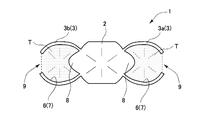
- FIG. 1 is a perspective view showing a state in which a partial denture 1 of the present invention is mounted.
- a partial denture 1 of the present invention is attached to a natural tooth missing portion S, which is a portion where natural teeth are missing, and is entirely made of resin, for example, approximately 80% polypropylene by weight. Ingredients.
- the resin material constituting the partial denture 1 will be described later in detail.
- the partial denture 1 is located at the center and has a denture portion 2 that fills the natural tooth missing portion S, and both ends of the denture portion 2 are detachably engaged with the outer peripheral surface of an adjacent remaining natural tooth T, and the denture portion 2 Bridge portions 3a and 3b (hereinafter referred to as bridge portion 3 when both of the bridge portions 3a and 3b are included) are integrally molded (molded).
- the denture part 2 at the center of the partial denture 1 is solid and has the same shape as the missing tooth.
- a bridge portion 3a protruding outward in a C shape in plan view is formed at the right end of the denture portion 2, and a bridge portion 3b protruding outward in an inverted C shape in plan view is integrated with the denture portion 2 at the left end. Molded.
- the bridge portions 3 of the bridge portions 3a and 3b can be elastically deformed in the expanding / reducing (contracting / closing) direction. Further, both the bridge portions 3 have a thickness of about 1 mm to 3 mm, for example.
- the upper end position of the bridge part 3 in the front view is substantially the same height as the upper end position of the denture part 2, and the lower end position of the bridge part 3 is higher than the lower end position of the denture part 2.
- the height direction dimension h 3 is smaller than the height direction dimension H of the denture part 2.
- the upper and lower end surfaces of the bridge portions 3a and 3b are open, and the bridge portion 3 exposes the natural tooth upper surface 5 that is the upper surface of the remaining natural tooth T in a state of being engaged with the remaining natural tooth T. At the same time, it has a curved portion 11 covering the upper peripheral edge 10 of the remaining natural tooth T.
- the curved portion 11 is curved (or refracted) inward from the upper ends of the bridge portions 3a and 3b to contact the upper surface of the remaining natural tooth T.
- the curved portion 11 is curved (or refracted) inward from the upper ends of the bridge portions 3a and 3b to contact the upper surface of the remaining natural tooth T.
- the curved portion 11 is formed along the shape of the remaining natural tooth T so that a part of the tooth is covered.
- illustration of the curved part 11 is abbreviate
- the curved portion 11 may not be formed.
- the bridge portion 3 extends integrally from the denture portion 2 toward the remaining natural teeth T located on both sides of the denture portion 2 (see also FIG. 3), and the outer peripheral surface of the remaining natural teeth T on both sides.
- the denture part 2 is fixed by detachably engaging with the remaining natural teeth T so as to sandwich 7 from inside and outside in an elastically deformed state.
- the bridge portion 3 has a C-shape and an inverted C-shape in plan view, and thus has an open portion 9 opened to the outside.
- the open portion 9 prevents the remaining natural tooth T2 further outside the remaining natural tooth T engaged with the bridge portion 3 from interfering with the bridge portion 3 (see also FIG. 6). Further, the opening 9 can be appropriately widened or narrowed in the elastic deformation state described above, and can be matched with the outer peripheral surface 7 of the remaining natural tooth T to be engaged.
- the inner peripheral surface 6 of the bridge portion 3 is formed so as to correspond to the shape of the outer peripheral surface 7 of the remaining natural tooth T, and the bridge portion 3 and the remaining natural tooth T are fitted together. By doing so, positioning in the front-rear and left-right directions when the partial denture 1 is mounted is performed.
- the inner peripheral surface 6 is appropriately formed according to the shape of the user's remaining natural teeth T.
- the denture part 2 and the bridge part 3 are colors similar to the natural tooth color, and when the partial denture 1 is mounted, it can be seen as if all the remaining natural teeth T, so that a sense of unity And high aesthetics.
- the remaining natural tooth color can be appropriately adjusted according to the color of the user's remaining natural tooth T, and specifically, an intermediate color from yellow to white is colored.
- a yellow pigment is used for coloring, and white titanium oxide is added thereto, whereby “yellowish white” coloring closer to the color of the remaining natural teeth T can be made to the resin.
- the bridge outer peripheral surface 12 which is the outer peripheral surface of the bridge portion 3 shown in FIG. 4 and the like is formed in a gloss and shape close to the outer peripheral surface 7 of the remaining natural tooth T. Therefore, the partial denture 1 has an appearance factor very close to the remaining natural tooth T in combination with the above-described remaining natural tooth color.
- the partial denture 1 of this invention demonstrated the example which uses a polypropylene as a main component, about 80% of polyethylene may be made into a main component, for example by weight ratio.
- the partial denture 1 when the partial denture 1 is mounted, the partial denture 1 is mounted from the upper side to the lower side with respect to the natural tooth missing portion S which is a portion where the natural tooth is missing.
- the bridge portion 3 is elastically deformed while the inner peripheral surface 6 of the bridge portion 3 is abutted and positioned on the outer peripheral surface 7 of the remaining natural tooth T, and the partial denture 1 is engaged with the remaining natural tooth T.
- the partial denture 1 is invisible.
- Example 2 to 8 showing other examples of Example 1 will be described below.
- symbol is provided to the part which is common in Example 1, and description is abbreviate
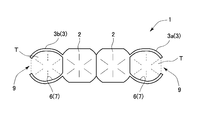
- Example 2 As shown in FIG. 7, a plurality of central denture parts 2 are formed, for example, two are continuously formed, and a C-shaped bridge part 3 a in plan view is formed at the right end of the continuous denture parts 2.
- a bridge portion 3b having an inverted C shape in plan view can be integrally formed at the left end. This example can be applied when there are two natural tooth missing portions S where natural teeth are missing.
- Example 3 As shown in FIG. 8, for example, three central denture parts 2 are continuously formed, and a C-shaped bridge part 3 a in a plan view is formed at the right end of the continuous denture part 2, and a reverse C is obtained in a plan view at the left end.
- Each of the letter-shaped bridge portions 3b can be integrally formed. This example is applicable when there are three natural tooth missing portions S.
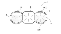
- Example 4 As shown in FIG. 9, when there is no remaining natural tooth T2 adjacent to the remaining natural tooth T, that is, only when the remaining natural tooth T is not continuous with either one, the O-shaped bridge portion 3f in plan view and The denture part 2 can be integrally formed. Specifically, for example, an O-shaped bridge portion 3f is integrally formed at the left end of the central denture portion 2 in plan view. As described above, this example is effective when there is no remaining natural tooth T on the left side (back side) further than the O-shaped bridge portion 3f. This is because there is no possibility that the O-shaped bridge portion 3f interferes with the remaining natural tooth T2 that is further adjacent (on the back side) with the remaining natural tooth T to be engaged.
- the bridge part 3 can also be shape
- FIG. In this case, an inverted C-shaped bridge portion is applied in plan view.
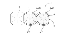
- Example 5 As shown in FIG. 10, two C-shaped bridge portions 3 a are integrally formed at the right end of the denture portion 2, and the bridge portion 3 may not be formed at the left end of the denture portion 2.
- the present invention can be applied particularly when the natural tooth missing portion S is continuous, for example, when two are consecutive.
- this example shows an example in which two continuous bridge portions 3a are integrally formed at the right end of the denture portion 2, the bridge portion 3 is formed at the left end of the denture portion 2 as in the example of FIG. Can do. In this case as well, an inverted C-shaped bridge portion is applied in plan view.
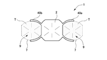
- bridge portions 40 a and 40 b each having a semicircular shape in plan view and each having an open portion 9 on the outside can be integrally formed at both ends of the denture portion 2.
- the bridge portions 40a and 40b may have a length that does not interfere with fixing the denture portion 2 by sandwiching the outer peripheral surface 7 of the remaining natural tooth T while elastically deforming. If it does in this way, the material cost of the partial denture 1 can be saved compared with another Example, a manufacturing cost can be suppressed, and the wearing feeling of the partial denture 1 will become light for a user.
- a protruding portion 8 that is protruded in the direction of the remaining natural tooth T may be provided at both ends of the denture portion 2.
- the protruding portion 8 is formed in a convex shape in a fitting form corresponding to the concave portion of the outer peripheral surface 7 of the remaining natural tooth T. In this way, when the partial denture 1 is mounted, the denture part 2 itself can be firmly fitted to the remaining natural tooth T by the protruding part 8 together with the engagement of the bridge part 3, so that it is more reliable.
- the partial denture 1 can be attached.
- the denture parts 2 and the bridge parts 3 can be integrally formed alternately. More specifically, an inverted C-shaped bridge portion 3b in plan view at the left end of the partial denture 1, followed by a denture portion 2, a bridge portion 3c connecting the denture portion 2 at the center, and a denture portion 2 at the right end
- Each of the letter-shaped bridge portions 3a is integrally formed.
- the combination of the bridge part 3 and the denture part 2 is not limited to this, although not illustrated, for example, from the left end toward the right end, the bridge part 3b, the denture part 2, the denture part 2, the bridge part 3c, According to the state of the user's remaining natural tooth T in the order of the denture part 2, the bridge part 3a, etc., it can shape
- the remaining natural tooth T engaged by the bridge portion 3 is not a healthy tooth due to a decayed tooth or the like, the fixing of the denture portion 2 by the bridge portion 3 tends to be insufficient.
- the bridge part 3c which connects the denture part 2 to the center is applied as in this embodiment, the adjacent remaining natural tooth T can be further engaged and the denture part 2 can be fixed.
- This embodiment can be combined with the examples of the second to fourth embodiments.
- the partial denture 1 can be applied to the missing front tooth portion, and can be applied to any portion of the missing top and bottom teeth. can do.
- the resin material of the partial denture 1 is, for example, 70% to 100% polypropylene by weight. More specifically, 80% polypropylene by weight was used as the main component, and 18% ethylene alpha olefin copolymer was copolymerized therewith to obtain a purified polypropylene. For this polypropylene, 80% polypropylene homopolymer [CH 2 —CH (CH 3 )] m by weight ratio, ethylene propylene copolymer [CH 2 —CH (CH 3 )] m— [CH 2 — as ethylene ⁇ -olefin copolymer.
- n is used at a ratio of 18%, and further additives include magnesium stearate 0.1%, titanium oxide 0.03%, pigments (eg, aluminum lakes and bengaras that are legal dyes, organic and inorganic pigments, etc. 1 pigment is selected from among the above, or a plurality of pigments are selected and blended and used) and adjusted to 0.03%.
- pigments eg, aluminum lakes and bengaras that are legal dyes, organic and inorganic pigments, etc. 1 pigment is selected from among the above, or a plurality of pigments are selected and blended and used
- the same amount of iron oxide may be blended instead of titanium oxide, or the total amount of titanium oxide and iron oxide may be 0.03%.
- ethylene butene 1 copolymer may be used as the ethylene ⁇ -olefin copolymer, and further, polyethylene may be contained, for example, 18% instead of the ethylene ⁇ -olefin copolymer.
- Substances other than those mentioned above are included as inevitable impurities within a range of 2% or less, as additives for a predetermined addition purpose, or as a sum of inevitable impurities and a predetermined additive, which is essential for the present invention. Regardless of requirements and effects, they do not affect them and can be ignored.
- polyethylene can also be used as the main component of the other resin material of the partial denture 1, for example, in the range of 70% to 100% polyethylene by weight. More specifically, 80% polyethylene by weight is the main component, and the remainder is appropriately blended with, for example, magnesium stearate.
- any of an injection molding method, a compression molding method, a vacuum pressure molding method, and the like can be easily processed using a general-purpose molding machine.
- the resin material of the partial denture 1 is generally a pellet raw material, which is placed in the barrel of a general-purpose resin molding machine, and the furnace temperature is set to 180 to 230 degrees Celsius. Set and soften and melt the raw material to perform injection molding.
- the resin fluidity is high, and it is possible to accurately reproduce the details of the molded product.
- the partial denture 1 made of the resin material thus obtained has the following features and characteristics. 1. There is no resin allergic reaction in the human body. 2. For all additives, this resin component is highly safe because it does not dissolve in the oral cavity, and there is no concern about the additives and pigments in terms of safety (the resin material of the partial denture 1 of the present invention). For example, the melting point is about 180 degrees Celsius). 3. By blending magnesium stearate as an additive, all the pigments are evenly mixed at the time of resin dyeing, and the dyeability is greatly enhanced. 4). By blending magnesium stearate, the smoothness of the surface of the resin itself is increased and the slipping is improved, so that it is effective for desorption of the partial denture 1. 5.
- titanium oxide iron oxide
- the resin material constituting the partial denture 1 has an extremely low water absorption compared to conventional resin materials, the propagation of various bacteria and the deterioration of physical properties of the resin due to water absorption are extremely small. Moreover, since the elasticity is high, the fitting state can be maintained without the bridge portion 3 spreading. 7. Since the resin material constituting the partial denture 1 is less likely to absorb moisture in the air than conventional resin materials, there is no problem even when stored at room temperature, and heat is used to remove moisture even during injection molding. There is no need to dry. 8). In addition, although the resin material which comprises the partial denture 1 is generally a pellet-shaped thing, it is not limited to this, A sheet-like thing may be sufficient.
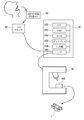
- FIG. 14 and FIG. 15 show a first manufacturing method of the denture 1.
- FIG. 14 is a system diagram for manufacturing the denture 1.
- the denture manufacturing system includes a computer 20, a camera 30, and a cutting machine 40.
- the computer 20 includes a CPU 200, a RAM 201, a ROM 202, a display 203, an input unit 204, and an interface unit 205 (I / F).
- the CPU 200 executes information processing such as various calculations to be described later for manufacturing a denture
- the RAM 201 is a temporary storage unit as a work area of the CPU 200.
- the ROM 202 is a non-volatile storage unit that stores software, data, and the like necessary for manufacturing a denture.
- the display 203 displays various images for manufacturing a denture, for example, as a liquid crystal display unit.
- the input unit 204 receives an input for manufacturing a denture from an operator (operator, dental technician) as described later, for example, as a mouse or a keyboard.
- the I / F 205 connects the computer 20, the camera 30, and the cutting machine 40 so that information can be exchanged.
- the camera 30 is provided for photographing the patient's mouth.
- the camera 30 outputs the image data to the computer 20 as a digital signal.
- the image captured by the camera 30 may be a monochrome image or a full color image.
- the cutting machine 40 is an automatic cutting machine (processing machine) having servo mechanisms in, for example, the three axis directions of x, y, and z axes by NC control (numerical control). The cutting process is automatically executed.
- FIG. 15 shows a denture manufacturing procedure using the denture manufacturing system of FIG.
- the processing procedure of FIG. 15 may be programmed in advance and stored in, for example, the ROM 202, and the computer 20 may automatically execute the processing procedure.
- the operator may be a dentist or a dental technician who is involved in the work for manufacturing a denture.
- the operator uses the camera 30 to capture an image including the natural teeth remaining in the oral cavity of the patient (who needs a denture) and the missing natural tooth portion.
- the photographed image is sent to a computer as digital data.
- the computer 20 receives the captured image, the computer 20 automatically executes the subsequent processing from S20.
- the CPU 200 calculates, on the RAM 201, three-dimensional (3D) shape data including the remaining natural tooth and the natural tooth missing portion in the patient's oral cavity.
- the photographing process in S10 may be a plurality of images taken from different angles.
- 3D data is calculated from the image (s) using a known image processing technique.
- the CPU 200 calculates the shape of the partial denture 1 so as to fill a portion where the natural tooth is missing in the 3D shape in the oral cavity of the patient.
- This calculation is first performed from the above-described calculation of the denture part 2 in the denture 1, for example.
- a standard tooth shape at the location of the missing natural tooth is called from the ROM 202, and the size and shape of the missing space in the shape of the patient's missing position, the shape of the adjacent remaining tooth, etc. What is necessary is just to calculate together.
- standard tooth shape data may be stored in the ROM 202 in advance, and it may be called and partially corrected.
- the bridge part 3 is calculated following the calculation of the denture part 2.
- the bridge portion 3 having a shape that appropriately holds the adjacent remaining natural tooth by the elastic restoring force is calculated according to the surface shape of the remaining natural tooth adjacent to the missing portion.
- the shape data of the standard bridge portion is stored in the ROM 202 in advance, and an appropriate shape is called and partially corrected according to the surface shape of the remaining natural tooth adjacent to the missing portion. It may be used.
- the shape of the denture 1 is automatically calculated by the computer 20 as described above. However, it is preferable to check the shape of the denture 1 with the eyes of the operator and if correction (fine correction) is necessary. Steps S40 and S50 are followed for that purpose.
- the CPU 200 displays the denture image calculated in S30 on the display 203.
- the display it is preferable to display the denture image superimposed on the image in the oral cavity of the patient.
- the operator corrects the denture shape on the display 203 using the input unit 204 (for example, a mouse) while viewing the displayed image.
- the CPU 200 receives this input and corrects the denture shape data.
- the shape of the denture 1 is finally determined. Note that the processing of S40 and S50 may be omitted, and the shape of the denture 1 may be determined by only fully automatic processing from the imaging of S10.
- the CPU 200 sends the shape data of the denture 1 to the cutting machine 40, and the cutting machine 40 has the same shape as the shape data confirmed in S50 (or calculated in S30) and sent to the cutting machine 40.
- the set resin block 100 (block-shaped resin) is automatically cut, and the denture part 2 and the bridge part 3 are continuously formed integrally by continuous cutting, so that the denture 1 Create
- the component of the resin block 100 may be the above-described resin component.
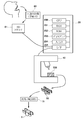
- FIGS. 16 and 17 the same reference numerals as those in FIGS. 14 and 15 have the same configuration and processing contents, and thus description thereof is omitted.
- the system shown in FIG. 16 includes a computer 20, a camera 30, and a cutting machine 40 as in FIG. Under this system configuration, the same processing as in FIG. 15 is executed from S10 to S50, as shown in FIG.
- the CPU 200 sends the shape data of the denture 1 to the cutting machine 40.
- a dental wax (wax) block 500 (block-shaped wax) is set in the cutting machine 40.
- the cutting machine 40 cuts the wax 500 so as to have the same shape as the sent shape data, and creates a wax denture 50.
- a known denture manufacturing process using wax dentures is performed. That is, the wax denture 50 is buried in the investment material (sand mold, plaster, etc.) 51 in S80. Then, the investment material 51 is cured by elapse of time. Next, in S90, in the investment material 51 including the wax denture, only the wax is washed away with hot water, for example (so-called flowing wax).
- the shape of the wax denture 50 created in S70 may be finely corrected by the operator by manual operation (for example, wearing it in the patient's oral cavity). In this case, there is an advantage that the shape can be more adapted to the patient.
- a resin in a fluid state is injected (filled, filled, injected) into the cavity in the investment material 51 formed by melting the wax.
- the resin component may be the same as the resin component of the denture 1 described above.
- a resin part is dug out from the investment material 51 by S110, and a resin-made denture 1 is completed when an operator passes through final processes, such as grinding
- the above manufacturing method has an advantage that the technique of the known lost wax method can be partially used.
- the computer 20 and the cutting machine 40 are used as in the system of FIG. 14, but the dental impression material 60 and the three-dimensional (3D) scanner 61 are used instead of the camera 30. Is used.
- the manufacturing procedure first copies (collects) an impression in the oral cavity of the patient (negative shape of the intraoral shape) using the dental impression material 60 in S5.
- the material of the dental impression material may be, for example, alginate or silicon.
- the intraoral impression (impression material obtained by copying the intraoral impression) 60 is scanned by the 3D scanner 61, three-dimensional shape information in the patient's oral cavity is acquired as digital data, and sent to the computer 20.
- the impression 60 may be taken by the camera 30, and the three-dimensional shape may be calculated by the computer 20.
- the denture 1 is created from the sent three-dimensional data, as in the first manufacturing method described above.
- FIGS. 20 and 21 the same reference numerals as those in the other drawings are the same in configuration and processing contents, and thus description thereof is omitted.
- the system used in the fourth manufacturing method includes a dental impression material 60 and a 3D scanner 61 as in FIG. 18, and includes a dental wax block 500 and an investment material 51 as in FIG. And after performing the process from S5 to S50 similarly to the 3rd manufacturing method, the process of S70 to S110 is performed similarly to the 2nd manufacturing method, and the denture 1 is created.
- the above four manufacturing methods are naturally used not only for the denture 1 of FIGS. 1 to 6 but also for the manufacture of all other dentures 1 after FIG. If the above manufacturing method is used, the labor of the operator can be remarkably reduced by making many processes automatic processes by a computer or a cutting machine. Also, quality variations due to the skill of the operator can be avoided.
- the denture 1 described above is a so-called one-piece denture in which the denture portion 2 and the bridge portion 3 are made of the same resin, but the present invention is not limited to this, and the denture portion 2 and the bridge portion 3 May be a two-piece type formed of different resin components.
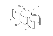
- FIGS. 22A to 22C show a denture 1 'in which the denture 1 of FIGS. 1 to 6 is a two-piece type.
- FIG. 22B shows the denture portion 2'
- FIG. 22C shows the bridge portion 3 '.
- the denture portion 2 ' has a cylindrical shape having a lid portion 21 at the top and an opening at the bottom.
- the hole 20 is formed in the position of the both sides of the figure in the side surface of denture part 2 '.
- the bridge portion 3 ′ includes an inverted C-shaped bridge 3 b on the left side in the drawing (hereinafter, the shape is a plan view), a C-shaped bridge 3 a on the right side in the drawing, and a connecting portion 3 d for connecting them.
- Each of the bridge 3b and the bridge 3a holds the remaining natural tooth from the inside and outside (that is, from the tongue side and the cheek side or the lip side), as in the case of FIGS.
- Both the denture part 2 'and the bridge part 3' may be solid.
- the hole 20 for the connection part 3d exists in denture part 2 '.
- the connecting portion 3d is inserted into the cylindrical shape of the denture portion 2 ′.
- the connecting portion 3d passing through the hole 20 connects the bridge 3a and the bridge 3b within the denture portion 2 ′.
- the connecting portion 3d is included in the denture portion 2 '.
- the denture part 2 and the bridge part 2 may be integrally formed with the same component resin mainly composed of polypropylene or polyethylene colored in a color corresponding to the natural tooth color.
- the resin constituting the denture portion 2 ′ is blended with acrylic rather than the resin constituting the bridge portion 3 ′.
- the weight ratio is large, and the resin constituting the bridge portion 3 ′ may have a higher blending weight ratio of polypropylene or polyethylene than the resin constituting the denture portion 2 ′.
- the denture part 2 ′ may have an acrylic compounding weight ratio of 100%, and the bridge part 3 ′ may have a compounding weight ratio of polypropylene or polyethylene of 100%.
- the component of the bridge portion 3 ′ in the two-piece type may be the same as the component of the one-piece type partial denture 1.
- acrylic resin generally includes the entire range defined as acrylic resin. That is, acrylic acid, methacrylic acid, and derivatives thereof such as triethylene glycol dimethacrylate, diethylene glycol dimethacrylate, ethylene glycol dimethacrylate, di (methacryloxy) trimethylhexamethylenediurethane, 2,2-bis [4- (2-hydroxy It is sufficient to include all polymers including monomers and polymers, such as -3-methacryloxypropoxy) phenyl] propane, ethyl methacrylate, and methyl methacrylate.
- each denture part 2 ' has the same structure as FIG. 22A to FIG. 22C, and the bridge
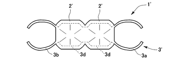
- FIG. 23 shows a denture 1 'in which the denture 1 of FIG.
- a denture portion 2 ' is formed continuously in the center of the figure, and an inverted C-shaped bridge 3b is formed on the left side of the figure, and a C-shaped bridge 3a is formed on the right side of the figure.
- the inverted C-shaped bridge 3b and the C-shaped bridge 3a are connected by a connecting portion 3d in the denture portion 2 'to form a bridge portion 3'.
- FIG. 24 shows a denture 1 'in which the denture 1 of FIG. Similarly to FIG. 8, three denture parts 2 'are continuously formed in the center of the figure, and an inverted C-shaped bridge 3b is formed on the left side of the figure, and a C-shaped bridge 3a is formed on the right side of the figure.
- the inverted C-shaped bridge 3b and the C-shaped bridge 3a are connected by a connecting portion 3d in the denture portion 2 'to form a bridge portion 3'.
- FIG. 25 shows a denture 1 'in which the denture 1 of FIG. Similarly to FIG. 9, a C-shaped bridge 3 a is formed on the right side of the denture portion 2 ′ and an O-shaped bridge 3 f is formed on the left side of the figure.
- the C-shaped bridge 3a sandwiches the remaining natural teeth from inside and outside, and the O-shaped bridge 3f surrounds and sandwiches the remaining natural teeth. There are no adjacent natural teeth on the left side of the O-shaped bridge 3f in the figure.
- the C-shaped bridge 3a and the O-shaped bridge 3f are connected by a connecting portion 3d in the denture portion 2 'to form a bridge portion 3'.
- FIG. 26 shows a denture 1 'in which the denture 1 of FIG. 10 is a two-piece type.
- two bridges 3 a and 3 a are continuously formed on the right side of the denture part 2 ′ in the figure, and no bridge is formed on the left side of the denture part 2 ′ in the figure.
- an insertion portion 3e is formed on the left side of the bridge 3a and the bridge 3a in the drawing, the insertion portion 3e is inserted into the denture portion 2 ′, and the bridge 3a and the bridge 3a become the denture portion 2 ′. It is fixed.
- FIG. 27 shows a denture 1 'in which the denture 1 of FIG. Similarly to FIG. 11, bridges 40 a and 40 b are formed on the right and left sides of the denture portion 2 ′, respectively, with the outside being an open portion. The bridges on both sides are connected by a connecting part 3d in the denture part 2 'to form a bridge part 3'.
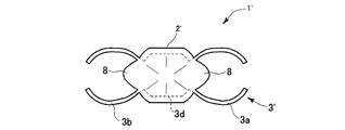
- FIG. 28 shows a denture 1 'in which the denture 1 of FIG. Similarly to FIG. 12, an inverted C-shaped bridge 3b is formed on the left side of the denture part 2 ′, and a C-shaped bridge 3a is formed on the right side of the denture part 2 ′. Is formed.
- the inverted C-shaped bridge 3b, the C-shaped bridge 3a, and the left and right protruding portions 8 are connected by the connecting portion 3d in the denture portion 2 'to form a bridge portion 3'.
- FIG. 29 shows a denture 1 'in which the denture 1 of FIG. 13 is a two-piece type. Similar to FIG. 13, denture parts 2 ′ and bridges are alternately formed. Specifically, a bridge 3c connecting the two denture parts 2 ′, an inverted C-shaped bridge 3b on the left side of the left denture part 2 ′ in the figure, and a right side of the denture part 2 ′ on the right side in the figure. C-shaped bridges 3a are respectively formed. The above three bridges are connected in the denture part 2 'by the connecting part 3d to form a bridge part 3'.
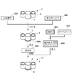
- FIG. 31 A method for manufacturing the two-piece partial denture 1 'is shown in FIGS. The manufacturing procedure of FIG. 31 will be described with reference to FIG.
- the manufacturing procedure of the two-piece partial denture 1 starts by collecting a patient's intraoral impression 60 using a dental impression material in S200. Subsequently, in S210, the intraoral impression is copied onto gypsum, and a gypsum model 250 having the intraoral shape of the patient is created. In S220, the worker manually creates the wax mold 300a of the bridge portion 3 'using the dental wax 300 on the model 250.
- the wax mold 300a is buried in the investment material 400.
- the temperature is raised in S240 to remove only the wax (flowing wax).
- Polypropylene 600 is filled into the cavity formed by the wax at S250.
- the bridge portion 3 ′ made of polypropylene is dug from the investment material in S 260, and the bridge portion 3 ′ is fitted into the plaster model 250 in S 270.
- the wax mold 300b of the denture part 2 ' is manually created by the operator using the dental wax 300 on the gypsum model 250 in which the bridge part 3' is fitted. Subsequently, in S290, the created wax mold 300b is buried in the investment material 400 while being combined with the bridge portion 3 '.
- a wax wax process is performed in S300. That is, the temperature is raised to remove only the wax. As a result, only the portion of the denture portion 2 'becomes a cavity.
- Acrylic 700 is filled into the cavity formed by flowing wax in S310.
- the acrylic 700 is polymerized and cured, the portion becomes the denture portion 2 ′ made of acrylic.
- the denture part 2 'made of acrylic is formed integrally with the bridge part 3' made of polypropylene.
- a two-piece type partial denture 1 ' having an acrylic denture part 2' and a bridge part 3 'made of polypropylene is manufactured.
- the above is the manufacturing method of the two-piece type partial denture 1 '.
- the part of polypropylene by said manufacturing method be resin which comprises the said partial denture 1, such as polyethylene.
- FIG. 32A shows a perspective view of an example of a three-piece partial denture.
- the three-piece partial denture 1 has a configuration in which a gingival part 4 is further added to the denture part 2 'and the bridge part 3' of the two-piece partial denture 1 '.
- the gingival part 4 is formed on the side surface of the denture part 2'. It is formed so as to surround the lower end of the figure (the end on the gingival side), and if the gingival part 4 is formed thicker as shown in the figure, it is preferable because it resembles the shape of natural gingiva. As shown in the perspective view of FIG. 32B, it may be formed so as to surround the entire circumference of the denture part 2 ′, or may be formed only in a portion that is not continuous over the entire circumference and that can be seen by others at the time of wearing.
- the material of the gingival part 4 may be, for example, polypropylene (resin mainly composed of polypropylene or polyethylene) in which a gingival color pigment (approximate color) is blended.
- a gingival color pigment approximately color
- the denture portion 2 ′ is not formed up to the lower end of the connecting portion 3d of the bridge portion 3 ′, and the gingival portion surrounds the entire periphery of the portion where the lower end of the connecting portion 3d is exposed. 4 may be formed so that the denture part 2 ′ is not formed up to the part hidden by the gingival part 4.
- FIG. 33 and 34 show a manufacturing method of the three-piece partial denture 1 ".
- the manufacturing procedure shown in FIG. 34 will be described with reference to FIG.
- the manufacturing procedure of the three-piece partial denture 1 is performed following the manufacturing procedure of the two-piece partial denture 1 'of Fig. 31. At this time, S330 may be omitted.
- a gingival color pigment 601 is added to the polypropylene 600.
- the two-piece type partial denture 1 ′ ie, the denture portion 2 ′ and the bridge portion 3 ′ is added to the gypsum model 250 in the oral cavity of the patient created in step S210 in step S350. ) Is set.
- the wax mold 300c of the gingiva 4 is created by the operator using the dental wax 300 manually on the gypsum model 250 in which the denture part 2 'and the bridge part 3' are fitted. Subsequently, in S370, the created wax mold 300c is buried in the investment material 400 while being combined with the denture portion 2 'and the bridge portion 3'.
- a wax wax process is performed in S380. That is, the temperature is raised to remove only the wax. Thereby, only the part of the gingival part 4 becomes a cavity.
- the pigment blended polypropylene 602 created in S340 is filled into the cavity formed by flowing wax.
- the portion becomes the gingival portion 4.
- the gingival portion 4 of the pigment-blended polypropylene 602 is integrally formed with an acrylic denture portion 2 ′ and a polypropylene bridge portion 3 ′.
- the gingival portion 4 may be added to the one-piece type partial denture 1 described above.
- An example is shown in FIG. In the manufacturing process, the same procedure as in FIG. 34 may be applied to the one-piece partial denture 1.
- the gingival color pigment 601 is blended with the polypropylene 600.
- the process of S340 may be performed in advance.
- the partial denture 1 (comprising the denture part 2 and the bridge part 3) is set on the plaster model 250 in the oral cavity of the patient created in the same process as S210.
- the wax mold 300c of the gingiva 4 is created by using the dental wax 300 manually by the operator on the gypsum model 250 in which the partial denture 1 is fitted. Subsequently, in S ⁇ b> 370, the created wax mold 300 c is embedded in the investment material 400 while being combined with the partial denture 1.
- a wax wax process is performed in S380. That is, the temperature is raised to remove only the wax. Thereby, only the part of the gingival part 4 becomes a cavity.
- the pigment blended polypropylene 602 created in S340 is filled into the cavity formed by flowing wax.
- the portion becomes the gingival portion 4.
- the gingival part 4 of the pigment-blended polypropylene 602 is formed integrally with a polypropylene partial denture 1 (denture part 2, bridge part 3).
- a partial denture 1 ′ ′′ having a denture part 2 and a bridge part 3 made of polypropylene and a gingival part 4 made of pigment-containing polypropylene is manufactured. Is done. The above is the manufacturing method of adding the gingival part 4 to the partial denture 1.
- the size of the gingival part 4 may be larger than the size shown in FIG. 32A.
- An example is shown in FIG. In this example, the gingival part 4 is extended downward in the figure so as to cover (a part of) the remaining gingiva of the user.
- the example of Fig. 36 applies to both the partial dentures 1 "and 1 '". This is suitable for patients whose gingiva has greatly deteriorated.
- the enlargement of the gingival part is limited to the example of Fig. 36. However, it may be applied to partial dentures of any shape of the present invention.
- the bridge portion 3 (3 ') may be formed in a cap-like shape by forming a portion covering the natural tooth like a lid.
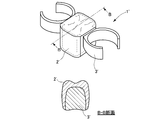
- FIGS. 37 shows one denture part 2 (2 ′) and one bridge part 3 (3 ′)
- FIG. 38 shows two denture parts 2 (2 ′) and one bridge part 3 (3 ′).
- the partial dentures in FIGS. 37 and 38 may be any of the partial dentures 1, 1 ′, 1 ′′, and 1 ′ ′′.
- the upper covering portion 3g is extended from the bridge portion so as to connect the cheek-side bridge portion and the tongue-side bridge portion above the bridge portion 3 (3 ′). Is formed.
- the upper cover portion 3g is formed so as to cover the occlusal surfaces of the remaining natural teeth sandwiched by the bridge portion 3 (3 '). Forming the upper cover portion 3g on the bridge portion 3 (3 ′) improves the clamping performance of the bridge portion 3 (3 ′), so that the fixing of the partial denture becomes more stable and the wearing feeling of the user is improved. .
- the bridge portion 3 (3 ′) is clearly formed only on one side of the denture portion 2 (2 ′) (for example, the mesial side, that is, the center side of the dentition). It is. Such a formation example is applied when the natural tooth is only one of the missing natural tooth portions.
- the bridge portion 3 (3 ') is formed only on one side of the denture portion 2 (2')
- the fixing to the remaining natural tooth by the bridge portion 3 (3 ') may become unstable.
- Forming the upper cover portion 3g on the bridge portion 3 (3 ') improves the clamping performance of the bridge portion 3 (3').
- the natural tooth when the natural tooth is only on one side of the denture part, it is particularly effective to secure the partial denture by forming the upper cover part 3g.
- the provision of the upper cover portion is not limited to the examples of FIGS. 37 and 38, and may be applied to partial dentures of any shape of the present invention. Further, as shown in FIGS. 37 and 38, the number of bridge portions is preferably the same as the number of denture portions for stable fixation.
- the bridge portion 3 (3 ') may be formed so as to surround the remaining natural teeth when there is a gap while providing the upper cover portion 3g.
- An example is shown in FIG.
- wall portions 3h and 3i are formed on the bridge portion 3 (3 ') in the example of FIG.
- the wall portions 3h and 3i are extended and formed from the bridge portion 3 (3 ') so as to contact the side surfaces of the remaining natural teeth.
- the left natural tooth is surrounded by the bridge portion 3 (3 ') and the wall portion 3h, and the upper portion (occlusion surface) is covered with the upper cover portion 3g.
- the remaining natural tooth on the right side is surrounded by the bridge portion 3 (3 '), the wall portion 3i, and the denture portion 2 (2'), and the upper portion (occlusion surface) is covered with the upper cover portion 3g.
- the wall portions 3h and 3i are formed in this way, the fixation to the remaining natural teeth is further stabilized, so that the user has a good wearing feeling.
- only one of the walls 3h and 3i may be formed according to the situation of the gaps forming the walls 3h and 3i.
- providing a wall part is not limited to the example of FIG. 39, What is necessary is just to apply to the partial dentures of all the shapes of this invention.
- the gingival part 4 may be formed on the lower part of the bridge part 3 in the figure. Examples are shown in FIGS. 40 to 42.
- FIG. 40 the gingival part 4 of FIG. 37 is extended to the lower part of the bridge part 3 (3 ') by the extension part 4a.
- FIG. 41 the gingival part 4 of FIG. 38 is extended by the extension part 4a to the illustration lower part of the bridge
- the gingival part 4 of FIG. 36 is extended by the extending part 4a to the lower part of the bridge part 3 (3 ') of both sides in the figure.
- the height of the bridge portion 3 (3 ') is also aligned with the height of the denture portion 2 (2').
- bridging part is not limited to the example of FIGS. 40-42, What is necessary is just to apply to the partial dentures of all shapes of this invention.
- the present invention is not limited to these embodiments, and is based on the knowledge of those skilled in the art without departing from the scope of the claims.
- Various changes are possible.
- the thickness of the acrylic part (denture part 2') is minimized, so that the component composition of the entire partial denture 1 'is mainly composed of polypropylene or polyethylene.
- the partial denture of the present invention is not limited to the specific tooth shape shown in the drawings, and is applied to all teeth without distinction between upper, lower, anterior and back teeth in the oral cavity. .
Landscapes
- Health & Medical Sciences (AREA)
- Oral & Maxillofacial Surgery (AREA)
- Dentistry (AREA)
- Epidemiology (AREA)
- Life Sciences & Earth Sciences (AREA)
- Animal Behavior & Ethology (AREA)
- General Health & Medical Sciences (AREA)
- Public Health (AREA)
- Veterinary Medicine (AREA)
- Engineering & Computer Science (AREA)
- Manufacturing & Machinery (AREA)
- Dental Prosthetics (AREA)
Abstract
L'invention porte sur un appareil dentaire (1) qui est adapté dans une section sans dent naturelle (S), qui est une région où une dent naturelle fait défaut, et est fait entièrement de résine avec, par exemple, le polypropylène en tant que composant principal à un rapport de poids de 80 %. Dans l'appareil dentaire partiel (1), une partie d'appareil dentaire (2) située au centre qui tombe dans la section sans dent naturelle (S), et des parties de pont (3a, 3b) sur les deux extrémités de la partie d'appareil dentaire (2) qui viennent en prise de manière détachable avec les surfaces externes des dents naturelles restantes (T) adjacentes pour immobiliser la partie d'appareil dentaire (2), sont toutes moulées en tant qu'unité. La partie d'appareil dentaire (2) et les parties de pont (3a, 3b) sont de la couleur des dents naturelles et lorsque l'appareil dentaire partiel (1) est porté, l'appareil dentaire partiel (1) entier peut être fabriqué pour ressembler aux dents naturelles restantes (T). L'invention porte sur un appareil dentaire partiel qui satisfait l'exigence d'avoir le même aspect que les dents naturelles restantes, tout en permettant de maintenir un état fermement immobilisé.
Applications Claiming Priority (2)
| Application Number | Priority Date | Filing Date | Title |
|---|---|---|---|
| JP2010232293 | 2010-10-15 | ||
| JP2010-232293 | 2010-10-15 |
Publications (1)
| Publication Number | Publication Date |
|---|---|
| WO2012049879A1 true WO2012049879A1 (fr) | 2012-04-19 |
Family
ID=45938116
Family Applications (1)
| Application Number | Title | Priority Date | Filing Date |
|---|---|---|---|
| PCT/JP2011/062388 Ceased WO2012049879A1 (fr) | 2010-10-15 | 2011-05-30 | Appareil dentaire et son procédé de fabrication |
Country Status (2)
| Country | Link |
|---|---|
| AU (1) | AU2010246413A1 (fr) |
| WO (1) | WO2012049879A1 (fr) |
Cited By (15)
| Publication number | Priority date | Publication date | Assignee | Title |
|---|---|---|---|---|
| WO2014103872A1 (fr) * | 2012-12-25 | 2014-07-03 | 株式会社ユニックスジャパン | Procédé de production d'article moulé à usage dentaire |
| JP2015042191A (ja) * | 2013-08-25 | 2015-03-05 | 順一 田代 | 歯科用ワックス |
| JP2015198850A (ja) * | 2014-04-09 | 2015-11-12 | 株式会社シケン | 歯科用の補綴模型に切削加工される切削プレート |
| CN106264764A (zh) * | 2015-06-09 | 2017-01-04 | 郑永如 | 和固定义齿一样牢固的活动义齿及其装卸方法 |
| CN107126283A (zh) * | 2016-02-29 | 2017-09-05 | 布莱登特有限责任两合公司 | 用于制作牙齿替换件的方法 |
| JP2018519911A (ja) * | 2015-07-21 | 2018-07-26 | シロナ・デンタル・システムズ・ゲゼルシャフト・ミット・ベシュレンクテル・ハフツング | 部分義歯の修復または調整のプランニング |
| CN108852541A (zh) * | 2018-08-07 | 2018-11-23 | 佛山科学技术学院 | 一种牙科修复用纯钛支架基托 |
| JP2019511293A (ja) * | 2016-04-12 | 2019-04-25 | ノベル バイオケア サーヴィシィズ アーゲー | 歯科修復物の製造方法 |
| CN110478070A (zh) * | 2019-07-22 | 2019-11-22 | 北京大学口腔医学院 | 一种可摘局部义齿的修复设计和制造方法 |
| EP3597142A1 (fr) * | 2018-07-20 | 2020-01-22 | DGSHAPE Corporation | Procédé de fabrication de base de prothèse, appareil de coupe et matériau de pièce à usiner |
| CN112807112A (zh) * | 2021-02-22 | 2021-05-18 | 上海市口腔病防治院 | 一种透明压膜式隐形义齿及其制作方法 |
| CN113440285A (zh) * | 2021-06-12 | 2021-09-28 | 杭州口腔医院集团有限公司 | 一种用于口腔修复的义齿及其义齿桥融合方法 |
| TWI747764B (zh) * | 2021-03-11 | 2021-11-21 | 艾瑞瓷精密股份有限公司 | 牙齒矯正組件及其磨除導板 |
| JP7232545B1 (ja) | 2021-12-27 | 2023-03-03 | 有限会社ワイ・デンタル・ラボ | 部分義歯の製造方法、及び、部分義歯 |
| JP7382613B1 (ja) | 2023-06-12 | 2023-11-17 | 有限会社ワイ・デンタル・ラボ | 部分義歯 |
Citations (7)
| Publication number | Priority date | Publication date | Assignee | Title |
|---|---|---|---|---|
| JPS59122109U (ja) * | 1983-02-05 | 1984-08-17 | 木暮 山人 | 架工義歯 |
| JPH0422356A (ja) * | 1990-05-17 | 1992-01-27 | Buhei Akaha | 義歯 |
| JP2000287998A (ja) * | 1999-04-07 | 2000-10-17 | Makoto Kameda | 歯牙用装置 |
| JP2002224144A (ja) * | 2001-02-05 | 2002-08-13 | Takashi Maeda | ポリエチレン義歯材料 |
| US20040086831A1 (en) * | 2002-11-06 | 2004-05-06 | Lai Yen-Ping | Detachable architecture of false teeth |
| JP2006167089A (ja) * | 2004-12-15 | 2006-06-29 | Microcast Laboratory:Kk | 無鈎固着義歯 |
| JP2008081446A (ja) * | 2006-09-27 | 2008-04-10 | Gc Dental Products Corp | 歯科補綴物パターン製作用光重合レジン組成物 |
-
2010
- 2010-11-25 AU AU2010246413A patent/AU2010246413A1/en not_active Abandoned
-
2011
- 2011-05-30 WO PCT/JP2011/062388 patent/WO2012049879A1/fr not_active Ceased
Patent Citations (7)
| Publication number | Priority date | Publication date | Assignee | Title |
|---|---|---|---|---|
| JPS59122109U (ja) * | 1983-02-05 | 1984-08-17 | 木暮 山人 | 架工義歯 |
| JPH0422356A (ja) * | 1990-05-17 | 1992-01-27 | Buhei Akaha | 義歯 |
| JP2000287998A (ja) * | 1999-04-07 | 2000-10-17 | Makoto Kameda | 歯牙用装置 |
| JP2002224144A (ja) * | 2001-02-05 | 2002-08-13 | Takashi Maeda | ポリエチレン義歯材料 |
| US20040086831A1 (en) * | 2002-11-06 | 2004-05-06 | Lai Yen-Ping | Detachable architecture of false teeth |
| JP2006167089A (ja) * | 2004-12-15 | 2006-06-29 | Microcast Laboratory:Kk | 無鈎固着義歯 |
| JP2008081446A (ja) * | 2006-09-27 | 2008-04-10 | Gc Dental Products Corp | 歯科補綴物パターン製作用光重合レジン組成物 |
Cited By (26)
| Publication number | Priority date | Publication date | Assignee | Title |
|---|---|---|---|---|
| WO2014103872A1 (fr) * | 2012-12-25 | 2014-07-03 | 株式会社ユニックスジャパン | Procédé de production d'article moulé à usage dentaire |
| JP2015042191A (ja) * | 2013-08-25 | 2015-03-05 | 順一 田代 | 歯科用ワックス |
| JP2015198850A (ja) * | 2014-04-09 | 2015-11-12 | 株式会社シケン | 歯科用の補綴模型に切削加工される切削プレート |
| CN108464872B (zh) * | 2015-06-09 | 2020-05-05 | 郑永如 | 和固定义齿一样牢固的活动义齿及其装卸方法 |
| CN106264764A (zh) * | 2015-06-09 | 2017-01-04 | 郑永如 | 和固定义齿一样牢固的活动义齿及其装卸方法 |
| CN111317588B (zh) * | 2015-06-09 | 2021-12-10 | 郑牧之 | 和固定义齿一样牢固的活动义齿及其装卸方法 |
| CN106264764B (zh) * | 2015-06-09 | 2018-03-23 | 郑永如 | 和固定义齿一样牢固的活动义齿及其装卸方法 |
| CN108464872A (zh) * | 2015-06-09 | 2018-08-31 | 郑永如 | 和固定义齿一样牢固的活动义齿及其装卸方法 |
| CN111317588A (zh) * | 2015-06-09 | 2020-06-23 | 郑永如 | 和固定义齿一样牢固的活动义齿及其装卸方法 |
| JP2018519911A (ja) * | 2015-07-21 | 2018-07-26 | シロナ・デンタル・システムズ・ゲゼルシャフト・ミット・ベシュレンクテル・ハフツング | 部分義歯の修復または調整のプランニング |
| CN107126283A (zh) * | 2016-02-29 | 2017-09-05 | 布莱登特有限责任两合公司 | 用于制作牙齿替换件的方法 |
| JP2019511293A (ja) * | 2016-04-12 | 2019-04-25 | ノベル バイオケア サーヴィシィズ アーゲー | 歯科修復物の製造方法 |
| US12324714B2 (en) | 2016-04-12 | 2025-06-10 | Nobel Biocare Services Ag | Method for producing a dental restoration |
| EP3597142A1 (fr) * | 2018-07-20 | 2020-01-22 | DGSHAPE Corporation | Procédé de fabrication de base de prothèse, appareil de coupe et matériau de pièce à usiner |
| JP2020010950A (ja) * | 2018-07-20 | 2020-01-23 | Dgshape株式会社 | 義歯床の製造方法および切削装置ならびに切削材料 |
| CN108852541A (zh) * | 2018-08-07 | 2018-11-23 | 佛山科学技术学院 | 一种牙科修复用纯钛支架基托 |
| CN108852541B (zh) * | 2018-08-07 | 2023-08-08 | 佛山科学技术学院 | 一种牙科修复用纯钛支架基托 |
| CN110478070A (zh) * | 2019-07-22 | 2019-11-22 | 北京大学口腔医学院 | 一种可摘局部义齿的修复设计和制造方法 |
| CN112807112A (zh) * | 2021-02-22 | 2021-05-18 | 上海市口腔病防治院 | 一种透明压膜式隐形义齿及其制作方法 |
| TWI747764B (zh) * | 2021-03-11 | 2021-11-21 | 艾瑞瓷精密股份有限公司 | 牙齒矯正組件及其磨除導板 |
| CN113440285A (zh) * | 2021-06-12 | 2021-09-28 | 杭州口腔医院集团有限公司 | 一种用于口腔修复的义齿及其义齿桥融合方法 |
| CN113440285B (zh) * | 2021-06-12 | 2023-06-30 | 杭州口腔医院集团有限公司 | 一种用于口腔修复的义齿及其义齿桥融合方法 |
| JP7232545B1 (ja) | 2021-12-27 | 2023-03-03 | 有限会社ワイ・デンタル・ラボ | 部分義歯の製造方法、及び、部分義歯 |
| JP2023096323A (ja) * | 2021-12-27 | 2023-07-07 | 有限会社ワイ・デンタル・ラボ | 部分義歯の製造方法、及び、部分義歯 |
| JP7382613B1 (ja) | 2023-06-12 | 2023-11-17 | 有限会社ワイ・デンタル・ラボ | 部分義歯 |
| JP2024178073A (ja) * | 2023-06-12 | 2024-12-24 | 有限会社ワイ・デンタル・ラボ | 部分義歯 |
Also Published As
| Publication number | Publication date |
|---|---|
| AU2010246413A1 (en) | 2012-05-03 |
Similar Documents
| Publication | Publication Date | Title |
|---|---|---|
| WO2012049879A1 (fr) | Appareil dentaire et son procédé de fabrication | |
| US12064312B2 (en) | Filling undercut areas of teeth relative to axes of appliance placement | |
| JP5932803B2 (ja) | 義歯をモデル化して製造する方法 | |
| US10327873B2 (en) | Method, system and user interface for creating a digital design for use in manufacturing a molding-shell for a dental restoration | |
| CN105982753B (zh) | 一种用于提高无牙颌个性化托盘在口腔内就位精度的方法 | |
| CN103027758B (zh) | 牙印模托盘 | |
| CN107260351A (zh) | 用于监测牙齿矫治状态的方法 | |
| CN108451661A (zh) | 具有定制美学的口腔数字化功能托盘及其使用方法 | |
| EP2624782A1 (fr) | Conception d'une couronne double comprenant une couronne interne et une couronne externe | |
| WO2016142407A1 (fr) | Procédé pour produire une prothèse dentaire | |
| EP3684289A1 (fr) | Procédés et dispositifs de fermeture d'un espace entre des dents | |
| WO2014103872A1 (fr) | Procédé de production d'article moulé à usage dentaire | |
| CN109259877A (zh) | 一种牙科产品的数字化定制生产工艺 | |
| Farah et al. | Comparison of the fit of crowns based on digital impressions with 3M ESPE Lava Chairside Oral Scanner COS vs. traditional impressions | |
| JP2018149079A (ja) | 義歯床、義歯床の製造方法、有床義歯及び有床義歯の製造方法 | |
| Mishra et al. | Fabrication of bar-retained tooth-supported mandibular overdenture | |
| US20230210632A1 (en) | Dental reparative article | |
| JP2860630B2 (ja) | 可動性連結人工歯及びその製造方法 | |
| WO2019188919A1 (fr) | Article dentaire moulé et matière de résine dentaire | |
| JP4309938B2 (ja) | 部分義歯 | |
| US20210015591A1 (en) | Method of fabricating a denture | |
| KR20120072792A (ko) | 치아 금형틀, 그를 이용한 틀니 제조방법과 그 틀니 | |
| JP5075633B2 (ja) | 透明な機能部付き人工歯 | |
| KR102098489B1 (ko) | 틀니 제작을 위한 왁스 틀니 제작방법 | |
| Çötert et al. | Transformation of teeth by using porcelain laminate veneers designed by diagnostic additive wax-up and resin composite mock-up |
Legal Events
| Date | Code | Title | Description |
|---|---|---|---|
| 121 | Ep: the epo has been informed by wipo that ep was designated in this application |
Ref document number: 11832321 Country of ref document: EP Kind code of ref document: A1 |
|
| NENP | Non-entry into the national phase |
Ref country code: DE |
|
| 122 | Ep: pct application non-entry in european phase |
Ref document number: 11832321 Country of ref document: EP Kind code of ref document: A1 |
|
| NENP | Non-entry into the national phase |
Ref country code: JP |