WO2012050133A1 - 建設機械 - Google Patents
建設機械 Download PDFInfo
- Publication number
- WO2012050133A1 WO2012050133A1 PCT/JP2011/073435 JP2011073435W WO2012050133A1 WO 2012050133 A1 WO2012050133 A1 WO 2012050133A1 JP 2011073435 W JP2011073435 W JP 2011073435W WO 2012050133 A1 WO2012050133 A1 WO 2012050133A1
- Authority
- WO
- WIPO (PCT)
- Prior art keywords
- storage device
- charge
- charge amount
- power
- construction machine
- Prior art date
- Legal status (The legal status is an assumption and is not a legal conclusion. Google has not performed a legal analysis and makes no representation as to the accuracy of the status listed.)
- Ceased
Links
Images




Classifications
-
- E—FIXED CONSTRUCTIONS
- E02—HYDRAULIC ENGINEERING; FOUNDATIONS; SOIL SHIFTING
- E02F—DREDGING; SOIL-SHIFTING
- E02F9/00—Component parts of dredgers or soil-shifting machines, not restricted to one of the kinds covered by groups E02F3/00 - E02F7/00
- E02F9/20—Drives; Control devices
-
- B—PERFORMING OPERATIONS; TRANSPORTING
- B60—VEHICLES IN GENERAL
- B60L—PROPULSION OF ELECTRICALLY-PROPELLED VEHICLES; SUPPLYING ELECTRIC POWER FOR AUXILIARY EQUIPMENT OF ELECTRICALLY-PROPELLED VEHICLES; ELECTRODYNAMIC BRAKE SYSTEMS FOR VEHICLES IN GENERAL; MAGNETIC SUSPENSION OR LEVITATION FOR VEHICLES; MONITORING OPERATING VARIABLES OF ELECTRICALLY-PROPELLED VEHICLES; ELECTRIC SAFETY DEVICES FOR ELECTRICALLY-PROPELLED VEHICLES
- B60L1/00—Supplying electric power to auxiliary equipment of vehicles
- B60L1/003—Supplying electric power to auxiliary equipment of vehicles to auxiliary motors, e.g. for pumps, compressors
-
- B—PERFORMING OPERATIONS; TRANSPORTING
- B60—VEHICLES IN GENERAL
- B60L—PROPULSION OF ELECTRICALLY-PROPELLED VEHICLES; SUPPLYING ELECTRIC POWER FOR AUXILIARY EQUIPMENT OF ELECTRICALLY-PROPELLED VEHICLES; ELECTRODYNAMIC BRAKE SYSTEMS FOR VEHICLES IN GENERAL; MAGNETIC SUSPENSION OR LEVITATION FOR VEHICLES; MONITORING OPERATING VARIABLES OF ELECTRICALLY-PROPELLED VEHICLES; ELECTRIC SAFETY DEVICES FOR ELECTRICALLY-PROPELLED VEHICLES
- B60L50/00—Electric propulsion with power supplied within the vehicle
- B60L50/10—Electric propulsion with power supplied within the vehicle using propulsion power supplied by engine-driven generators, e.g. generators driven by combustion engines
- B60L50/16—Electric propulsion with power supplied within the vehicle using propulsion power supplied by engine-driven generators, e.g. generators driven by combustion engines with provision for separate direct mechanical propulsion
-
- B—PERFORMING OPERATIONS; TRANSPORTING
- B60—VEHICLES IN GENERAL
- B60L—PROPULSION OF ELECTRICALLY-PROPELLED VEHICLES; SUPPLYING ELECTRIC POWER FOR AUXILIARY EQUIPMENT OF ELECTRICALLY-PROPELLED VEHICLES; ELECTRODYNAMIC BRAKE SYSTEMS FOR VEHICLES IN GENERAL; MAGNETIC SUSPENSION OR LEVITATION FOR VEHICLES; MONITORING OPERATING VARIABLES OF ELECTRICALLY-PROPELLED VEHICLES; ELECTRIC SAFETY DEVICES FOR ELECTRICALLY-PROPELLED VEHICLES
- B60L53/00—Methods of charging batteries, specially adapted for electric vehicles; Charging stations or on-board charging equipment therefor; Exchange of energy storage elements in electric vehicles
-
- B—PERFORMING OPERATIONS; TRANSPORTING
- B60—VEHICLES IN GENERAL
- B60L—PROPULSION OF ELECTRICALLY-PROPELLED VEHICLES; SUPPLYING ELECTRIC POWER FOR AUXILIARY EQUIPMENT OF ELECTRICALLY-PROPELLED VEHICLES; ELECTRODYNAMIC BRAKE SYSTEMS FOR VEHICLES IN GENERAL; MAGNETIC SUSPENSION OR LEVITATION FOR VEHICLES; MONITORING OPERATING VARIABLES OF ELECTRICALLY-PROPELLED VEHICLES; ELECTRIC SAFETY DEVICES FOR ELECTRICALLY-PROPELLED VEHICLES
- B60L53/00—Methods of charging batteries, specially adapted for electric vehicles; Charging stations or on-board charging equipment therefor; Exchange of energy storage elements in electric vehicles
- B60L53/10—Methods of charging batteries, specially adapted for electric vehicles; Charging stations or on-board charging equipment therefor; Exchange of energy storage elements in electric vehicles characterised by the energy transfer between the charging station and the vehicle
- B60L53/14—Conductive energy transfer
-
- B—PERFORMING OPERATIONS; TRANSPORTING
- B60—VEHICLES IN GENERAL
- B60L—PROPULSION OF ELECTRICALLY-PROPELLED VEHICLES; SUPPLYING ELECTRIC POWER FOR AUXILIARY EQUIPMENT OF ELECTRICALLY-PROPELLED VEHICLES; ELECTRODYNAMIC BRAKE SYSTEMS FOR VEHICLES IN GENERAL; MAGNETIC SUSPENSION OR LEVITATION FOR VEHICLES; MONITORING OPERATING VARIABLES OF ELECTRICALLY-PROPELLED VEHICLES; ELECTRIC SAFETY DEVICES FOR ELECTRICALLY-PROPELLED VEHICLES
- B60L58/00—Methods or circuit arrangements for monitoring or controlling batteries or fuel cells, specially adapted for electric vehicles
- B60L58/10—Methods or circuit arrangements for monitoring or controlling batteries or fuel cells, specially adapted for electric vehicles for monitoring or controlling batteries
- B60L58/12—Methods or circuit arrangements for monitoring or controlling batteries or fuel cells, specially adapted for electric vehicles for monitoring or controlling batteries responding to state of charge [SoC]
- B60L58/13—Maintaining the SoC within a determined range
-
- E—FIXED CONSTRUCTIONS
- E02—HYDRAULIC ENGINEERING; FOUNDATIONS; SOIL SHIFTING
- E02F—DREDGING; SOIL-SHIFTING
- E02F9/00—Component parts of dredgers or soil-shifting machines, not restricted to one of the kinds covered by groups E02F3/00 - E02F7/00
- E02F9/20—Drives; Control devices
- E02F9/2058—Electric or electro-mechanical or mechanical control devices of vehicle sub-units
- E02F9/2062—Control of propulsion units
- E02F9/2075—Control of propulsion units of the hybrid type
-
- E—FIXED CONSTRUCTIONS
- E02—HYDRAULIC ENGINEERING; FOUNDATIONS; SOIL SHIFTING
- E02F—DREDGING; SOIL-SHIFTING
- E02F9/00—Component parts of dredgers or soil-shifting machines, not restricted to one of the kinds covered by groups E02F3/00 - E02F7/00
- E02F9/20—Drives; Control devices
- E02F9/2058—Electric or electro-mechanical or mechanical control devices of vehicle sub-units
- E02F9/2091—Control of energy storage means for electrical energy, e.g. battery or capacitors
-
- F—MECHANICAL ENGINEERING; LIGHTING; HEATING; WEAPONS; BLASTING
- F02—COMBUSTION ENGINES; HOT-GAS OR COMBUSTION-PRODUCT ENGINE PLANTS
- F02D—CONTROLLING COMBUSTION ENGINES
- F02D29/00—Controlling engines, such controlling being peculiar to the devices driven thereby, the devices being other than parts or accessories essential to engine operation, e.g. controlling of engines by signals external thereto
- F02D29/02—Controlling engines, such controlling being peculiar to the devices driven thereby, the devices being other than parts or accessories essential to engine operation, e.g. controlling of engines by signals external thereto peculiar to engines driving vehicles; peculiar to engines driving variable pitch propellers
-
- B—PERFORMING OPERATIONS; TRANSPORTING
- B60—VEHICLES IN GENERAL
- B60L—PROPULSION OF ELECTRICALLY-PROPELLED VEHICLES; SUPPLYING ELECTRIC POWER FOR AUXILIARY EQUIPMENT OF ELECTRICALLY-PROPELLED VEHICLES; ELECTRODYNAMIC BRAKE SYSTEMS FOR VEHICLES IN GENERAL; MAGNETIC SUSPENSION OR LEVITATION FOR VEHICLES; MONITORING OPERATING VARIABLES OF ELECTRICALLY-PROPELLED VEHICLES; ELECTRIC SAFETY DEVICES FOR ELECTRICALLY-PROPELLED VEHICLES
- B60L2200/00—Type of vehicles
- B60L2200/40—Working vehicles
-
- B—PERFORMING OPERATIONS; TRANSPORTING
- B60—VEHICLES IN GENERAL
- B60L—PROPULSION OF ELECTRICALLY-PROPELLED VEHICLES; SUPPLYING ELECTRIC POWER FOR AUXILIARY EQUIPMENT OF ELECTRICALLY-PROPELLED VEHICLES; ELECTRODYNAMIC BRAKE SYSTEMS FOR VEHICLES IN GENERAL; MAGNETIC SUSPENSION OR LEVITATION FOR VEHICLES; MONITORING OPERATING VARIABLES OF ELECTRICALLY-PROPELLED VEHICLES; ELECTRIC SAFETY DEVICES FOR ELECTRICALLY-PROPELLED VEHICLES
- B60L2240/00—Control parameters of input or output; Target parameters
- B60L2240/40—Drive Train control parameters
- B60L2240/42—Drive Train control parameters related to electric machines
- B60L2240/423—Torque
-
- B—PERFORMING OPERATIONS; TRANSPORTING
- B60—VEHICLES IN GENERAL
- B60L—PROPULSION OF ELECTRICALLY-PROPELLED VEHICLES; SUPPLYING ELECTRIC POWER FOR AUXILIARY EQUIPMENT OF ELECTRICALLY-PROPELLED VEHICLES; ELECTRODYNAMIC BRAKE SYSTEMS FOR VEHICLES IN GENERAL; MAGNETIC SUSPENSION OR LEVITATION FOR VEHICLES; MONITORING OPERATING VARIABLES OF ELECTRICALLY-PROPELLED VEHICLES; ELECTRIC SAFETY DEVICES FOR ELECTRICALLY-PROPELLED VEHICLES
- B60L2240/00—Control parameters of input or output; Target parameters
- B60L2240/40—Drive Train control parameters
- B60L2240/42—Drive Train control parameters related to electric machines
- B60L2240/427—Voltage
-
- B—PERFORMING OPERATIONS; TRANSPORTING
- B60—VEHICLES IN GENERAL
- B60L—PROPULSION OF ELECTRICALLY-PROPELLED VEHICLES; SUPPLYING ELECTRIC POWER FOR AUXILIARY EQUIPMENT OF ELECTRICALLY-PROPELLED VEHICLES; ELECTRODYNAMIC BRAKE SYSTEMS FOR VEHICLES IN GENERAL; MAGNETIC SUSPENSION OR LEVITATION FOR VEHICLES; MONITORING OPERATING VARIABLES OF ELECTRICALLY-PROPELLED VEHICLES; ELECTRIC SAFETY DEVICES FOR ELECTRICALLY-PROPELLED VEHICLES
- B60L2240/00—Control parameters of input or output; Target parameters
- B60L2240/40—Drive Train control parameters
- B60L2240/54—Drive Train control parameters related to batteries
- B60L2240/547—Voltage
-
- B—PERFORMING OPERATIONS; TRANSPORTING
- B60—VEHICLES IN GENERAL
- B60L—PROPULSION OF ELECTRICALLY-PROPELLED VEHICLES; SUPPLYING ELECTRIC POWER FOR AUXILIARY EQUIPMENT OF ELECTRICALLY-PROPELLED VEHICLES; ELECTRODYNAMIC BRAKE SYSTEMS FOR VEHICLES IN GENERAL; MAGNETIC SUSPENSION OR LEVITATION FOR VEHICLES; MONITORING OPERATING VARIABLES OF ELECTRICALLY-PROPELLED VEHICLES; ELECTRIC SAFETY DEVICES FOR ELECTRICALLY-PROPELLED VEHICLES
- B60L2240/00—Control parameters of input or output; Target parameters
- B60L2240/80—Time limits
-
- Y—GENERAL TAGGING OF NEW TECHNOLOGICAL DEVELOPMENTS; GENERAL TAGGING OF CROSS-SECTIONAL TECHNOLOGIES SPANNING OVER SEVERAL SECTIONS OF THE IPC; TECHNICAL SUBJECTS COVERED BY FORMER USPC CROSS-REFERENCE ART COLLECTIONS [XRACs] AND DIGESTS
- Y02—TECHNOLOGIES OR APPLICATIONS FOR MITIGATION OR ADAPTATION AGAINST CLIMATE CHANGE
- Y02T—CLIMATE CHANGE MITIGATION TECHNOLOGIES RELATED TO TRANSPORTATION
- Y02T10/00—Road transport of goods or passengers
- Y02T10/60—Other road transportation technologies with climate change mitigation effect
- Y02T10/64—Electric machine technologies in electromobility
-
- Y—GENERAL TAGGING OF NEW TECHNOLOGICAL DEVELOPMENTS; GENERAL TAGGING OF CROSS-SECTIONAL TECHNOLOGIES SPANNING OVER SEVERAL SECTIONS OF THE IPC; TECHNICAL SUBJECTS COVERED BY FORMER USPC CROSS-REFERENCE ART COLLECTIONS [XRACs] AND DIGESTS
- Y02—TECHNOLOGIES OR APPLICATIONS FOR MITIGATION OR ADAPTATION AGAINST CLIMATE CHANGE
- Y02T—CLIMATE CHANGE MITIGATION TECHNOLOGIES RELATED TO TRANSPORTATION
- Y02T10/00—Road transport of goods or passengers
- Y02T10/60—Other road transportation technologies with climate change mitigation effect
- Y02T10/70—Energy storage systems for electromobility, e.g. batteries
-
- Y—GENERAL TAGGING OF NEW TECHNOLOGICAL DEVELOPMENTS; GENERAL TAGGING OF CROSS-SECTIONAL TECHNOLOGIES SPANNING OVER SEVERAL SECTIONS OF THE IPC; TECHNICAL SUBJECTS COVERED BY FORMER USPC CROSS-REFERENCE ART COLLECTIONS [XRACs] AND DIGESTS
- Y02—TECHNOLOGIES OR APPLICATIONS FOR MITIGATION OR ADAPTATION AGAINST CLIMATE CHANGE
- Y02T—CLIMATE CHANGE MITIGATION TECHNOLOGIES RELATED TO TRANSPORTATION
- Y02T10/00—Road transport of goods or passengers
- Y02T10/60—Other road transportation technologies with climate change mitigation effect
- Y02T10/7072—Electromobility specific charging systems or methods for batteries, ultracapacitors, supercapacitors or double-layer capacitors
-
- Y—GENERAL TAGGING OF NEW TECHNOLOGICAL DEVELOPMENTS; GENERAL TAGGING OF CROSS-SECTIONAL TECHNOLOGIES SPANNING OVER SEVERAL SECTIONS OF THE IPC; TECHNICAL SUBJECTS COVERED BY FORMER USPC CROSS-REFERENCE ART COLLECTIONS [XRACs] AND DIGESTS
- Y02—TECHNOLOGIES OR APPLICATIONS FOR MITIGATION OR ADAPTATION AGAINST CLIMATE CHANGE
- Y02T—CLIMATE CHANGE MITIGATION TECHNOLOGIES RELATED TO TRANSPORTATION
- Y02T90/00—Enabling technologies or technologies with a potential or indirect contribution to GHG emissions mitigation
- Y02T90/10—Technologies relating to charging of electric vehicles
- Y02T90/14—Plug-in electric vehicles
Definitions
- the present invention relates to a construction machine such as a hydraulic shovel mounted with an engine and a power storage device.
- a construction machine such as a hydraulic shovel has a hydraulic pump driven by an engine, and the hydraulic pump drives a hydraulic work device such as a bucket cylinder, an arm cylinder, a boom cylinder and a traveling hydraulic motor.
- a hydraulic work device such as a bucket cylinder, an arm cylinder, a boom cylinder and a traveling hydraulic motor.
- Patent Document 1 a method for efficiently using a motor has also been devised, and there is a prior art of this kind, for example, as shown in Patent Document 1.
- This is a hybrid in which a motor and a generator are connected to the engine, and the remaining power at the time of light load work is charged to the battery, while the power is extracted from the battery at the time of heavy load work and used for heavy load work.
- the engine is automatically stopped to store the storage power of the storage device.
- the engine is automatically restarted when the work load is higher than the set value or the charge amount is lower than the set value during no-engine work. That is, it is possible to stably operate the engine in a light load state, which is a high efficiency area, and to save the charge amount of the power storage device within a certain range while performing energy saving operation while compensating for the shortage of engine output with respect to work load with the motor. It is
- Patent Document 2 when the charge amount of the storage device is insufficient, the power generated by the generator rotationally driven by the engine is charged to the storage device, and when the charge amount is sufficient, the engine It is characterized in that excessive charging of the power storage device is prevented by setting the output to a minimum idling state or stopping the engine.
- the charge amount of the power storage device is constant. It is controlled to keep it in the range.
- the lead storage battery used as a power storage device in the present invention has a large power loss at the time of charging, and it is desirable that the power storage device preferentially discharges.
- an object of the present invention is to realize a storage device control means capable of performing a control such that the storage device charged in advance at the start of the work is used up within the working time, and performing discharge preferentially. Do.
- Another object of the present invention is to disclose a technology that uses a commercial power source or the like with low energy cost when charging the power storage device in advance.
- the object of the present invention is as follows.
- the first object is to realize a plug-in construction machine capable of charging from an external power source such as a commercial power source having a low energy cost via a charging device in a power storage device mounted to assist the engine. It is.
- the second object is that, when a power storage device to be charged using an external power supply is mounted, assist can be performed by the power storage device in a situation where the engine output is insufficient, and the charge amount is insufficient during work and the assist becomes impossible.
- the third object is to realize a construction machine which can use the power storage device efficiently.
- the present application includes a plurality of means for solving the above object, and one example thereof is an engine, an assist motor mechanically connected coaxially with the engine, and an assist motor and a storage device,
- the storage device has a charging device connected to the storage device, and the storage device performs charging from an external power supply through the charging device. Is possible.
- a construction machine comprising: an engine; an assist motor mechanically connected coaxially with the engine; and a power converter connected to the assist motor and the storage device to control the voltage of the assist motor and the voltage of the storage device. Then, the charge amount target value of the power storage device is determined based on the estimated working time of the construction machine, and the charge / discharge amount is controlled based on the charge amount target value.
- the present invention it is possible to realize a construction machine on which an engine can be mounted and an external power source can be used. Further, in a situation where the engine output is insufficient, assist by the power storage device is possible, and it is possible to realize a construction machine that efficiently charges and discharges the power storage device so that the charge amount is used up at the end of work.
- FIGS. 1 to 6 and 9 A first embodiment of the present invention will be described with reference to FIGS. 1 to 6 and 9.
- the device efficiency is not considered in order to make the description easy to understand, but more accurate control is possible by controlling in consideration of the device efficiency.
- FIG. 1 is a view showing the configuration of a hydraulic shovel (a typical example of a construction machine) to which the present embodiment is applied.
- the hydraulic shovel 18 has a traveling body 201 and a swing body 202.
- the traveling body 201 has a function of causing the construction machine to travel by the traveling hydraulic motor 8.
- the pivoting body 202 is rotated relative to the traveling body 201 by the pivoting mechanism 12, and the boom 203, the arm 204, and the bucket for performing the digging operation on the other front side (for example, forward and right) of the pivoting body 202 205 is provided.
- the boom 203, the arm 204, and the bucket 205 are driven by the boom cylinder 7, the arm cylinder 6, and the bucket cylinder 5, respectively. Further, the revolving unit 202 is provided with a cab 206, and an operator gets on the cab 206 to operate a construction machine.
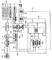
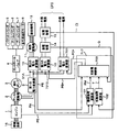
- FIG. 2 shows the overall configuration of a construction machine drive system for driving the construction machine shown in FIG.
- the drive system includes an engine 1, an assist motor 2, a hydraulic pump 3, a control valve 4, a bucket cylinder 5, an arm cylinder 6, a boom cylinder 7, a traveling hydraulic motor 8, power converters 9 and 10, a swing motor 11, It comprises a turning mechanism 12, a power storage device 14, a charging device 15, an accessory load 16, and a control device 17.
- the engine 1 is subjected to rotational speed control based on a target rotational speed set by the operator.
- the engine 1 is mechanically coupled to the assist motor 2.
- An accessory load 16 such as a fan or a compressor for an air conditioner is mechanically coupled to the engine 1 and is connected to the assist motor 2 via the engine 1.
- the hydraulic pump 3 is connected to an assist motor 2 mechanically coupled to the engine 1.
- the hydraulic pump 3 is driven by the motive power of the engine 1 and the assist motor 2 to supply hydraulic fluid to the control valve 4, and the control valve 4 operates based on the operating lever operated by the operator. , And controls hydraulic oil supplied to the boom cylinder 7 and the traveling hydraulic motor 8.
- the assist motor 2 assists the engine 1 at the time of power running, and drives the hydraulic pump 3 and the auxiliary load 16 by the power of the engine 1 and the assist motor 2.
- the assist motor 2 generates electric power by the engine 1 at the time of regeneration.
- the hydraulic work device comprises a bucket cylinder 5, an arm cylinder 6, a boom cylinder 7, and a traveling hydraulic motor 8, and is installed on the revolving unit 202 and the traveling unit 201.
- the first power converter 9 is connected to the assist motor 2, and converts a DC voltage into an AC voltage and an AC voltage into a DC voltage. That is, the AC voltage generated by the assist motor 2 is converted to a DC voltage through the first power converter 9.
- a second power converter 10 is connected to the DC side of the first power converter 9.
- the second power converter 10 also converts the DC voltage into an AC voltage and converts the AC voltage into a DC voltage.
- the swing motor 11 is connected, and through the control lever information operated by the operator, the first power converter 9 and the second power converter 10 Thus, it is possible to control the rotational speed and torque of the swing motor 11.
- the swing mechanism 12 is connected to the swing motor 11 and is driven via the swing motor 11.
- the first power converter 9 and the second power converter 10 are connected via the DC bus 91A, and the third power converter 13 is connected to the DC bus 91A via the DC bus 91B. ing.
- the voltage of the DC buses 91A and 91B is converted by the third power converter 13, and the power storage device 14 is connected to the side from which the voltage-converted DC current is output.
- the storage device 14 a lead storage battery can be used.
- Power storage device 14 is connected to charging device 15.
- charging device 15 is connectable to external power supply EPS, and can convert current obtained from external power supply EPS from alternating current to direct current and can convert power storage device 14 to a chargeable voltage. Therefore, the storage device 14 can be charged from the external power supply EPS.
- charging of power storage device 14 can be performed by a commercial external power supply with low energy cost during a rest time when no work is performed. For example, when working in the daytime and not in the nighttime, it is possible to connect to the external power supply EPS and charge at nighttime and use the charged power in the daytime work. Thereby, when the power required for the work exceeds the engine output for a short time, the power can be supplied from the power storage device 14 and the engine 1 needs to be able to cope with the engine output corresponding to the average work output. Engines will be available. Small capacity engines are also expected to be cost effective because they are inexpensive and generally efficient.
- control device 17 is connected to the engine 1, the first power converter 9, the second power converter 10, the third power converter 13, the storage device 14 and the charging device 15 through the communication means. ing.
- the control device 17 is configured of a machine load calculation unit 101, a working time calculation unit 102, and a charge / discharge control unit 103.
- the charge amount Q of 14 and the charge information CI of the charging device 15 are input, and the calculated charge / discharge command PB * is output to the third power converter 13.
- Third power converter 13 converts the power between DC bus 91 B and power storage device 14 to each other, thereby charging power storage device 14 to match charge / discharge command PB * output from control device 17. Control the amount of discharge PB. Therefore, it becomes possible to control the release charge of the storage device 14.
- charge / discharge command PB * is a positive value
- power storage device 14 is a discharge, and when it is a negative value, it is a command value that charges.
- the mechanical load calculation unit 101 the engine output PE and the assist motor mechanical output PA are input, and the mechanical load PM corresponding to the load used by the hydraulic pump 3 and the accessory load 16 is calculated using Equation (1).
- the working time calculation unit 102 calculates the working time T of the construction machine by integrating the charging information CI from the charging device 15 and the time when the construction machine is activated. It should be noted that when the power storage device 14 is charged from the external power supply EPS and the power storage device 14 is fully charged, the working time T is reset.
- charge / discharge control unit 103 turning motor machine output PS, machine load PM, operation time T, and charge amount Q of power storage device 14 are input, and charge / discharge command PB * is sent to third power converter 13. Output.
- the charge / discharge control unit 103 includes a charge amount target value calculation unit 301, a subtractor 302, 310, a first charge / discharge target value calculation unit 303, a minimum value calculator 304, 312, and a second charge / discharge target value calculation unit 305. , Third charge / discharge target value calculation unit 306, adders 307, 308, and 309, and a maximum value calculation unit 311.
- the charge amount target value calculation unit 301 calculates the charge amount target value Q * based on the working time T of the construction machine and the estimated working time Ts set in advance.
- Charge amount target value Q * is set to be the maximum charge amount Qmax of power storage device 14 when work time T is 0, and the minimum charge amount Qmin when work time T is the work end.
- the characteristic is monotonically decreasing.
- the power stored in the storage device 14 can be used systematically, and charging can be performed during operation. It is possible to prevent the problem that the amount is insufficient and the assist is impossible, and the problem that it is not possible to use up at the time of working weight and can not reduce the fuel consumption sufficiently. Therefore, not only the storage device can be efficiently used, but also the size reduction can be achieved.
- the assumed work time Ts is set to 8 hours which is considered to be an average work time, but in consideration of a general work time, it is appropriate to set it in the range of 6 to 10 hours.
- the estimated work time Ts may be set to a work time setting unit 321 that can be set by the worker, and any time can be set.
- the estimated work time Ts is changed in the middle of work, according to the elapsed time and the remaining work time, charging is performed so that the charge amount target value Q * becomes the minimum charge amount Qmin at the set work time Ts.
- the characteristic of the amount target value calculation unit 301 is changed.
- the worker has set the working time, it is also possible to set the remaining working time.
- a clock function and a work end time setting means capable of setting the work end time are provided instead of the work time setting means, the same function can be obtained by calculating the work time from the time and the work end time. It is feasible. Also in this case, the work end time can be changed midway. Furthermore, it is possible to provide a function to improve the calculation accuracy of work time by inputting the break time zone of work such as lunch break together.
- adder 302 In order to control charge amount Q of power storage device 14 to match the characteristic of charge amount target value Q *, adder 302 first subtracts charge amount target value Q * from charge amount Q of power storage device 14. Then, the charge amount margin value ⁇ Q is calculated.
- the first charge / discharge target value calculation unit 303 receives the charge amount margin value ⁇ Q calculated by the adder 302, and calculates a first charge / discharge target value PB1.
- the first charge / discharge target value PB1 is a discharge amount corresponding to the charge amount margin value ⁇ Q, 0 when the charge amount margin value ⁇ Q is smaller than 0, and 0 when the charge amount margin value ⁇ Q is 0 or more.
- the target value is such that Q is discharged to match the charge amount target value Q *.
- the minimum value calculation unit 304 Furthermore, in the minimum value calculation unit 304, the calculated first charge / discharge target value PB1 and the swing motor machine output PS are input, and the smaller one of them is output as the second charge / discharge target value PB2. That is, the minimum value calculation unit 304 outputs a value obtained by limiting the swing motor machine output PS as the upper limit value.
- the second charge / discharge target value calculation unit 305 calculates a third charge / discharge target value PB3 based on the charge amount margin value ⁇ Q.
- the third charge / discharge target value PB3 is 0 when the charge amount margin value ⁇ Q is smaller than the first charge amount margin set value Qa set in advance, and the charge amount margin value ⁇ Q is the first charge amount margin set value In the case of Qa or more, it is a discharge target value that can be discharged such that the charge amount Q matches Q * + Qa, which is a value larger than the charge amount target value Q *.
- the third charge / discharge target value calculation unit 306 calculates a fourth charge / discharge target value PB4 based on the charge amount margin value ⁇ Q.
- the fourth charge / discharge target value PB4 is 0 when the charge amount margin value ⁇ Q is larger than the second charge amount margin set value ⁇ Qc determined in advance, and the charge amount margin value ⁇ Q is the second charge amount margin set value In the case of -Qc or less, it is a charge target value that can be charged so that the charge amount Q matches Q * -Qc, which is a value smaller than the charge amount target value Q *.
- the addition value of these target values is calculated by the adder 307.
- the addition value calculated in this way is further input to the adder 308, the addition value with the second charge / discharge target value PB2 is calculated, and the fifth charge / discharge target value PB5 is calculated.
- the adder 309 the mechanical load PM and the swing motor mechanical output PS are input, the addition value is calculated, and the total output Pload which is the power necessary for the entire drive system is output.
- the engine output shortage amount ⁇ P is calculated by subtracting the maximum output PEmax of the engine from the total output Pload calculated by the adder 309. That is, when the engine output shortage amount ⁇ P is a positive value, the maximum output PEmax of the engine is insufficient with respect to the total output Pload, and a negative value indicates that there is a margin.
- the engine output shortage ⁇ P and the fifth charge / discharge target value PB5 calculated in this manner are input to the maximum value calculator 311, and the larger value is output. That is, a value limited with the engine output shortage amount ⁇ P as the lower limit value is output.
- the value output from the maximum value calculator 311 and the total output Pload are input, and the smaller value is output as the release charge amount PB. That is, a value limited with total output Pload as the upper limit value is output, and this value is output as charge / discharge command PB *.
- the fifth charge / discharge target value PB5 is the charge / discharge command PB * with the engine output shortage amount ⁇ P as the lower limit value and the total output Pload as the upper limit value via the maximum value calculator 311 and the minimum value calculator 312. Are output to the third power converter 13.
- third power converter 13 Since third power converter 13 is connected to power storage device 14, power storage device 14 can be charged or discharged via the third power converter based on the input charge / discharge command.
- FIG. 9 shows the state of the system with respect to the total output Pload and the charge / discharge amount PB.
- Region A is a region where the charge / discharge amount PB is excessive and the power becomes excessive even if the engine output PE is zero.
- Region B is a region where the charge / discharge amount PB is insufficient, and the total output Pload can not be satisfied even if the engine output PE is the maximum output PEmax of the engine.
- Region C is a region in which the power is excessive even if the charge / discharge amount PB is insufficient and the engine output PE is zero.
- Region D is a region where the charge / discharge amount PB is excessive, and even if the engine output PE is the maximum output PEmax of the engine, the total output Pload and the charge amount can not be covered. Therefore, the charge / discharge command PB * is limited as described above because it is necessary to prevent the charge / discharge amount PB from entering the regions A to D.
- the engine power PE is in balance with the assist motor mechanical power PA and the mechanical load PM.
- the rotational speed of the engine 1 is temporarily reduced, but the rotational speed of the engine 1 is satisfied so as to satisfy the equation (1).
- the engine output PE is increased until the amount of increase in the mechanical load PM and the increase in the engine output PE are balanced by the control. Therefore, except for the transient short time, the engine output PE satisfies the equation (2). That is, even when the mechanical load PM is increased or decreased by the operation of the operating lever by the operator, the engine output PE corresponding to that is output. The same applies to the case where the assist motor mechanical output PA increases or decreases.
- the assist motor mechanical output PA is a swing motor mechanical output PS And control to balance the charge and discharge amount PB.
- the assist motor machine output PA becomes equation (3) except for a transient short time. That is, even when the swing motor machine output PS increases or decreases due to the swing operation, the assist motor machine output PA is adjusted accordingly. Furthermore, as described above, since the engine output PE is determined by equation (2) according to the increase or decrease of PA, the engine output PE is output according to the turning operation.
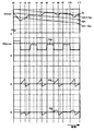
- FIG. 6 is a time chart showing the relationship between the charge amount target value Q * and the charge amount Q, the machine load PM, the swing motor machine output PS, and the charge / discharge amount PB from the top.
- the initial values of the charge amount Q and the working time T are respectively the maximum charge amount Qmax and 0, and when the operator operates the operation lever, the mechanical load PM and the swing motor mechanical output PS are as shown in the figure. It is output.
- the charge amount target value Q * calculated by the charge amount target value calculation unit 301 matches the maximum charge amount Qmax, so the charge amount target value Q * and the charge amount
- the first charge / discharge target value PB1, the third charge / discharge target value PB3, and the fourth charge / discharge target value PB4 are zero.
- the swing motor machine output PS is zero
- the second charge / discharge target value PB2 is zero
- the fifth charge / discharge target value PB5 is also zero.
- the engine output shortage ⁇ P which is the lower limit value of the charge / discharge command PB * is positive. It becomes the value of. Therefore, the charge / discharge command PB * becomes the engine output shortage amount ⁇ P. As a result, the power storage device 14 discharges, and it is possible to compensate for the shortage of the maximum output PEmax of the engine with respect to the mechanical load PM.
- the charge amount target value Q * decreases with time, the decrease of the charge amount Q of the storage device 14 due to discharge is sharper than the charge amount target value Q *, so the charge amount margin value ⁇ Q is It becomes a negative value, and the fifth charge / discharge target value PB5 becomes 0 or a negative value. Therefore, the charge / discharge command PB * becomes the engine output shortage amount ⁇ P.
- the engine output shortage ⁇ P is a negative value because the mechanical load PM decreases and the total output Pload becomes smaller than the maximum output PEmax of the engine, and the charge / discharge command PB * directly outputs the fifth charge / discharge target value PB5 Do.
- power storage device 14 is charged such that the charge amount Q which is too small matches Q * -Qc.
- the charge amount Q is smaller than Q * -Qc and is largely insufficient relative to the charge amount target value Q *, the power storage device 14 is charged, and Q near the charge amount target value Q * The charge amount Q is controlled to match * -Qc.
- the swing motor 11 switches to deceleration, the swing motor machine output PS switches to a negative value (regeneration), and thereafter the speed starts to decrease.
- the second charge / discharge target value PB2 is limited by the swing motor machine output PS, and becomes a swing motor machine output PS that is a negative value (charging), and the charge / discharge command PB * also becomes the swing motor machine output PS.
- the charge amount Q exceeds Q * -Qc and the fourth charge / discharge target value PB4 becomes 0, charging continues with the second charge / discharge target value PB2.
- the power storage device 14 can be charged with the power regenerated by the swing motor 11.
- the mechanical load PM increases in a range that does not exceed the maximum output PEmax of the engine, the swing motor 11 stops, and the swing motor mechanical output PS becomes zero. Since the charge amount Q is between Q * -Qc and Q * and the charge amount margin value ⁇ Q is between -Qc and 0, the first charge / discharge target value PB1, the third charge / discharge target value PB3, The fourth charge / discharge target value PB4 is zero. Further, since the swing motor machine output PS is zero, the second charge / discharge target value PB2 is zero. Thus, the fifth charge / discharge target value PB5 is zero. Furthermore, since the mechanical load PM and the total output Pload do not exceed the maximum output PEmax of the engine, the charge / discharge command PB * is 0 without limitation, and the charge amount Q is constant.
- the mechanical load PM decreases as at time t1, and the swing motor mechanical output PS increases. Furthermore, when the charge amount Q becomes equal to or more than the charge amount target value Q *, the charge amount margin value ⁇ Q becomes equal to or more than 0, and the first charge / discharge target value PB1 becomes a positive value (discharge). As a result, charge and discharge command PB * is a positive value (discharge), and power storage device 14 is discharged such that charge amount Q matches charge amount target value Q *.
- the mechanical load PM decreases as at time t1, and the swing motor machine output PS increases. Since the charge amount Q is equal to or greater than Q * + Qa, the charge amount margin value ⁇ Q becomes equal to or greater than Qa, and the third charge / discharge target value PB3 becomes a positive value (discharge), and the first charge / discharge target value PB1 is also Since it is a positive value (discharge), the second charge / discharge target value PB2 limited by the swing motor machine output PS is also a positive value (discharge). As a result, the charge / discharge command PB * becomes a positive value (discharge) larger than the swing motor mechanical output PS, and the storage device 14 is discharged more than the power used by the swing motor 11.
- the assist motor 2 assists the engine 1 through the first power converter 9 by the discharge power exceeding the swing motor mechanical output PS.
- the charge / discharge command PB * matches the swing motor mechanical output PS, and the electric power used by the swing motor 11 is a power storage device It is discharged from 14.
- the first charge / discharge target value PB1 is output as the charge / discharge command PB *. Is discharged from power storage device 14 so as to match charge amount target value Q *.
- the turning motor machine output PS switches to a negative value (regeneration) as at time t5, and as at time t5, the charge / discharge command PB * becomes a negative value (charging), and the turning motor 11 is regenerated.
- An operation of charging power storage device 14 is performed.
- the regenerative power is basically charged to the storage device 14 as described in the operation from time t2 to t3.
- the operation for the charge amount Q is as follows.
- the charge amount Q is equal to or less than Q * -Qc, the charge amount is largely insufficient relative to the charge amount target value Q *, and the total power Pload is the power necessary for work exceeding the maximum output PEmax of the engine. It is necessary to perform the charging operation to secure the Therefore, as described in the operation from time t1 to t2, control is performed so that the charge amount Q matches Q * ⁇ Qc.
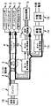
- FIG. 4 shows the time when the charge / discharge command PB * is larger than the swing motor machine output PS, and at this time, the assist motor 2 performs the powering operation and assists the insufficient energy by the discharge power of the storage device 14. ing.
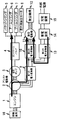
- FIG. 5 shows the time when the charge / discharge command PB * is smaller than the swing motor machine output PS, and at this time, the assist motor 2 performs the regeneration operation.
- the storage device 14 supplies power to the swing motor 11 via the third power converter 13 and the second power converter 10, and the engine 1 is an assist motor There is one that supplies power to the swing motor 11 via the second power converter 9 and the second power converter 10.
- the device efficiency when power is supplied to the swing motor 11 by the discharge power of the storage device 14, the number of devices to be interposed is small and the conversion loss of power or power is also small. There is no need to increase it, and the fuel consumption reduction effect of the engine is large.
- the power storage device 14 is discharged so that the power flow shown in FIG. 5 is obtained, that is, the charge / discharge command PB * becomes smaller than the swing motor machine output PS. Therefore, as described in the operation of time t7 to t8, the reduction effect of the fuel consumption of the engine 1 with respect to the discharge amount is increased by operating the charge / discharge command PB * so as to be equal to or less than the swing motor machine output PS. It is possible.
- the estimated work time Ts set in the charge amount target value calculation unit 301 is 8 hours, but setting change means that can be operated by the operator such as operation buttons is provided, and the set value of the estimated work time It is also possible to change Ts.
- the setting change means is preferably provided in the cab 206 so that the operator can operate, and the assumed work time input by the operator is controlled via the communication means, preferably the control device 17, preferably a release charge control unit. The value is input to the charge target value calculation unit 301 of FIG.
- setting change means 341 such as a button operation by which the operator can specify the presence or absence of charging is provided to make the charge amount target value Q * constant.
- the setting change unit 341 for designating the presence or absence of charge is provided in the cab 206 so that the operator can operate, and the information on the presence or absence of charge input by the operator is controlled via the communication means It is input to the device 17. Even in this case, it is possible to discharge for assisting when the engine output is insufficient or to charge and reuse the regenerative electric power of the swing motor 11 in the power storage device, and the fuel consumption can be reduced. is there.
- the storage device can not be performed by the external power supply if the pause time is longer than the time set in advance and charging from the external power supply is not performed. It is also possible to judge it as an environment. At this time, it is also possible to perform the operation without reducing the charge amount of the power storage device by switching the charge amount target value Q * constant as well.
- similar control can be performed by adding the electric load power to the swing motor machine output PS.
- FIGS. 7 and 8 A second embodiment of the present invention will be described with reference to FIGS. 7 and 8.
- the device efficiency is not considered in order to make the description easy to understand.
- the same reference numerals are given to the same components as in the first embodiment, and the description will be omitted.
- FIG. 7 shows the overall configuration of the construction machine drive system.
- the drive system in the present embodiment has a fourth power converter 701 added to the drive system shown in FIG. 1 and is provided with a control device 717 instead of the control device 17.
- the fourth power converter 701, the first power converter 9, and the second power converter 10 are connected via the DC buses 91A and 91B which are DC side circuits, and the power from the external power supply EPS is To convert the voltage of
- the power supplied from the external power supply EPS supplies power to each part via the DC buses 91A and 91B based on the constant power supply command PC * via the fourth power converter 701.
- the supplied power is smaller than the maximum output PEmax of the engine 1.
- the control device 717 includes a charge / discharge control unit 703 in place of the charge / discharge control unit 103 in the control device 17 of FIG. 1.
- the charge / discharge control unit 703 receives the swing motor machine output PS, the machine load PM, the working time T, and the charge amount Q from the storage device 14, and supplies the charge / discharge command PB * to the third power converter 13, and Constant power supply command PC * is output to power converter 701 of FIG.
- the charge / discharge control unit 703 has an adder / subtractor 801, a minimum value calculator 802, and a subtractor 803 added to the charge / discharge control unit 103 shown in FIG.
- the adder-subtractor 801 calculates a value obtained by subtracting the fourth charge / discharge target value PB4 from the sum of the machine load PM and the swing motor machine output PS.
- the minimum value calculator 802 always outputs the smaller one of the value calculated and output by the adder / subtractor 801 and the maximum constantly supplied power PCmax of the fourth power converter 701 as the constantly supplied power command PC *.
- the subtractor 803 subtracts the constant power supply command PC * from the swing motor machine output PS, and outputs a corrected swing motor machine output PS 'to be used instead of the swing motor machine output PS of the charge / discharge control unit 103.
- This is equivalent to the supply power of the fourth power converter 701 being considered by the load of the DC bus and the swing motor machine output PS being reduced by the supply power. This is because it is necessary to consider the power supply of the power converter 701.
- the drive system of the construction machine of the second embodiment is equivalent to the reduction of the power consumption of the swing motor 11 by the supplied power when the swing motor 11 is in power running, and the supplied power when it is regenerated. This is equivalent to the increase in the regenerative electric power of the swing motor 11 by an amount, so that the same charge / discharge control of the power storage device 14 as that of the first embodiment is performed, and the same effect is obtained.
- the fuel consumption of the engine can be reduced.
- a small-capacity power converter can be used as the fourth power converter 701, and the fourth power converter 701 can operate even when external power is not supplied.
Landscapes
- Engineering & Computer Science (AREA)
- Power Engineering (AREA)
- Mechanical Engineering (AREA)
- Transportation (AREA)
- General Engineering & Computer Science (AREA)
- Structural Engineering (AREA)
- Mining & Mineral Resources (AREA)
- Civil Engineering (AREA)
- Chemical & Material Sciences (AREA)
- Combustion & Propulsion (AREA)
- Life Sciences & Earth Sciences (AREA)
- Sustainable Development (AREA)
- Sustainable Energy (AREA)
- Operation Control Of Excavators (AREA)
- Hybrid Electric Vehicles (AREA)
- Charge And Discharge Circuits For Batteries Or The Like (AREA)
- Electric Propulsion And Braking For Vehicles (AREA)
Abstract
Description
域Aは充放電量PBが過剰で、エンジン出力PEを0にしてもパワーが過剰となる領域である。領域Bは、充放電量PBが不足し、エンジン出力PEをエンジンの最大出力PEmaxにしても総出力Ploadをまかなえない領域である。領域Cは、充放電量PBが不足しエンジン出力PEを0にしてもパワーが過剰となる領域である。領域Dは充放電量PBが過剰で、エンジン出力PEをエンジンの最大出力PEmaxにしても総出力Ploadと充電量をまかなえない領域である。よって、充放電量PBを領域A~Dに入らないようにする必要が有るため、充放電指令PB*を前述のように制限している。
701が追加され、制御装置17に替えて制御装置717を備える。
2 アシスト電動機
3 油圧ポンプ
4 コントロールバルブ
5 バケットシリンダ
6 アームシリンダ
7 ブームシリンダ
8 走行用油圧モータ
9 第1の電力変換器
10 第2の電力変換器
11 旋回電動機
12 旋回機構
13 第3の電力変換器
14 蓄電装置
15 充電装置
17,717 制御装置
18 油圧ショベル
19 油圧作業装置
91A,91B 直流バス(直流側回路)
101 機械負荷演算部
102 作業時間演算部
103 充放電制御部
201 走行体
202 旋回体
203 ブーム
204 アーム
205 バケット
206 キャブ
301 充電量目標値演算部
303 第1の充放電目標値演算部
305 第2の充放電目標値演算部
306 第3の充放電目標値演算部
321 作業時間設定手段
341 設定変更手段(モードの設定手段)
701 第4の電力変換器
CI 充電情報
EPS 外部電源
PA アシスト電動機機械出力
PB 充放電量
PB* 充放電指令
PB1~PB5 第1~5の充放電目標値
PCmax 最大常時給電量
PC* 常時給電指令
PE エンジン出力
PEmax エンジンの最大出力
Pload 総出力
PM 機械負荷
PS 旋回電動機機械出力
PS′ 補正後旋回電動機機械出力
Q 充電量
Q* 充電量目標値
ΔQ 充電量余裕値
T 作業時間
Ts 想定作業時間(設定値)
Claims (10)
- エンジン(1)と、前記エンジン(1)と同軸上に機械的に接続されるアシスト電動機(2)と、前記アシスト電動機(2)および蓄電装置(14)に接続され、前記アシスト電動機(2)の電圧および前記蓄電装置(14)の電圧を制御する電力変換器(9,13)とを備える建設機械において、
前記蓄電装置(14)に接続される充電装置(15)を有し、前記蓄電装置(14)は前記充電装置(15)を介して外部電源(EPS)より充電が可能なことを特徴とする建設機械。 - 請求項1に記載の建設機械において、前記建設機械の想定作業時間(Ts)に基づき前記蓄電装置(14)の充電量目標値(Q*)を決定し、前記充電量目標値(Q*)に基づき充放電量を制御する充放電制御手段(103)を備えることを特徴とする建設機械。
- 請求項1または請求項2に記載の建設機械において、前記外部電源(EPS)から供給される電力を、前記電力変換器(9)の直流側回路(91A,791B)に供給する外部給電手段(701,717)を備えることを特徴とする建設機械。
- 請求項2に記載の建設機械において、前記充放電制御手段(103)は、前記建設機械の作業時間(T)と予め設定された想定作業時間(Ts)とに基づいて前記蓄電装置(14)の充電量目標値(Q*)を演算する充電量目標値演算部(301)と、前記蓄電装置(14)の充電量(Q)が前記充電量目標値(Q*)と所定の値(Qa)に基づいて決定される充電量(Q*+Qa)よりも大きい場合は、前記蓄電装置(14)の放電を行い、前記蓄電装置(14)の充電量(Q)が前記充電量目標値(Q*)と所定の値(Qc)に基づいて決定される充電量(Q*-Qc)よりも小さい場合は、前記蓄電装置(14)の充電を行う充放電目標値演算部(305,306)と、を備えることを特徴とする建設機械。
- 請求項2に記載の建設機械において、前記充放電制御手段(103)は、前記建設機械の作業時間(T)と予め設定された想定作業時間(Ts)とに基づいて前記蓄電装置(14)の充電量目標値(Q*)を演算する充電量目標値演算部(301)と、前記充電量目標値(Q*)に基づいて前記蓄電装置(14)の充放電を行う充放電目標値演算部(303,304,305,306)とを備え、
前記充放電目標値演算部(303,304,305,306)は、前記蓄電装置(14)の充電量(Q)が前記充電量目標値(Q*)と所定の値(Qa)に基づいて決定される充電量(Q*+Qa)よりも大きい場合は、前記蓄電装置(14)の放電を行い、前記蓄電装置(14)の充電量(Q)が前記充電量目標値(Q*)より大きい場合は、前記建設機械の電動駆動装置の消費電力(PS)より小さい電力にて前記蓄電装置(14)の放電を行い、前記蓄電装置(14)の充電量(Q)が、前記充電量目標値(Q*)と所定の値(Qc)に基づいて決定される充電量(Q*-Qc)よりも小さい場合は、前記蓄電装置(14)の充電を行うことを特徴とする建設機械。 - 請求項2、請求項4、請求項5のいずれか記載の建設機械において、想定作業時間(Ts)を設定できる設定手段(321)を備えることを特徴とする建設機械。
- 請求項2に記載の建設機械において、前記想定作業時間(Ts)は6乃至10時間であることを特徴とする建設機械。
- 請求項1乃至請求項3のいずれかに記載の建設機械において、前記外部電源(EPS)からの充電の有無を指定するモードの設定手段(341)を備え、前記モードに基づき前記蓄電装置(14)の充放電制御方法を切り替えることを特徴とする建設機械。
- 請求項2、請求項4、請求項5のいずれかに記載の建設機械において、前記外部電源(EPS)からの充電の有無を指定するモードの設定手段(341)を備え、前記モードに基づき前記充電量目標値(Q*)を切り替えることを特徴とする建設機械。
- 請求項8または請求項9に記載の建設機械において、前記建設機械の動作が停止した時間から予め設定した時間が経過し、前記外部電源(EPS)から前記蓄電装置(14)が充電されていない状態で起動した場合は、前記外部電源(EPS)からの充電無しのモードに切り替わることを特徴とする建設機械。
Priority Applications (5)
| Application Number | Priority Date | Filing Date | Title |
|---|---|---|---|
| JP2012538697A JP5605815B2 (ja) | 2010-10-15 | 2011-10-12 | 建設機械 |
| US13/879,444 US9421873B2 (en) | 2010-10-15 | 2011-10-12 | Construction machine |
| CN201180049640.6A CN103189576B (zh) | 2010-10-15 | 2011-10-12 | 工程机械 |
| EP11832567.9A EP2628859B1 (en) | 2010-10-15 | 2011-10-12 | Construction machine |
| KR1020137008833A KR101834592B1 (ko) | 2010-10-15 | 2011-10-12 | 건설 기계 |
Applications Claiming Priority (2)
| Application Number | Priority Date | Filing Date | Title |
|---|---|---|---|
| JP2010232075 | 2010-10-15 | ||
| JP2010-232075 | 2010-10-15 |
Publications (1)
| Publication Number | Publication Date |
|---|---|
| WO2012050133A1 true WO2012050133A1 (ja) | 2012-04-19 |
Family
ID=45938360
Family Applications (1)
| Application Number | Title | Priority Date | Filing Date |
|---|---|---|---|
| PCT/JP2011/073435 Ceased WO2012050133A1 (ja) | 2010-10-15 | 2011-10-12 | 建設機械 |
Country Status (6)
| Country | Link |
|---|---|
| US (1) | US9421873B2 (ja) |
| EP (1) | EP2628859B1 (ja) |
| JP (1) | JP5605815B2 (ja) |
| KR (1) | KR101834592B1 (ja) |
| CN (1) | CN103189576B (ja) |
| WO (1) | WO2012050133A1 (ja) |
Cited By (2)
| Publication number | Priority date | Publication date | Assignee | Title |
|---|---|---|---|---|
| JP2014148879A (ja) * | 2013-02-04 | 2014-08-21 | Hitachi Constr Mach Co Ltd | 作業機械 |
| JP2015131606A (ja) * | 2014-01-15 | 2015-07-23 | 株式会社小松製作所 | 作業車両及び作業車両の制御方法 |
Families Citing this family (7)
| Publication number | Priority date | Publication date | Assignee | Title |
|---|---|---|---|---|
| JP5226733B2 (ja) * | 2010-05-20 | 2013-07-03 | 株式会社小松製作所 | ハイブリッド建設機械およびハイブリッド建設機械の蓄電器容量計測方法 |
| SE542381C2 (sv) | 2012-04-23 | 2020-04-21 | Brokk Ab | Elektiskt driven demoleringsrobot och dess kraftförsörjningssystem |
| US9719498B2 (en) * | 2015-05-29 | 2017-08-01 | Caterpillar Inc. | System and method for recovering energy in a machine |
| JP6381491B2 (ja) * | 2015-07-07 | 2018-08-29 | 日立建機株式会社 | 建設機械の制御装置 |
| KR102330256B1 (ko) * | 2019-11-29 | 2021-11-24 | 주식회사 이스쿠스 | 가변 부하용 이중 전원식 전기동력 공급 시스템 |
| JP7389064B2 (ja) * | 2021-01-14 | 2023-11-29 | ヤンマーホールディングス株式会社 | 建設機械 |
| US12442339B2 (en) * | 2021-08-02 | 2025-10-14 | Transportation Ip Holdings, Llc | Electric drive system for a vehicle |
Citations (6)
| Publication number | Priority date | Publication date | Assignee | Title |
|---|---|---|---|---|
| JP2001011901A (ja) | 1999-06-30 | 2001-01-16 | Kobe Steel Ltd | ハイブリッド建設機械の作業情報処理装置 |
| JP2007120109A (ja) | 2005-10-27 | 2007-05-17 | Kobelco Contstruction Machinery Ltd | ハイブリッド式建設機械 |
| JP2009013632A (ja) * | 2007-07-03 | 2009-01-22 | Hitachi Constr Mach Co Ltd | 建設機械のエンジン制御装置 |
| JP2009197514A (ja) * | 2008-02-22 | 2009-09-03 | Hitachi Constr Mach Co Ltd | 電気駆動式作業機械 |
| JP2009215855A (ja) * | 2008-03-13 | 2009-09-24 | Hitachi Constr Mach Co Ltd | 作業機械 |
| WO2010114036A1 (ja) * | 2009-03-31 | 2010-10-07 | 日立建機株式会社 | 電源システムを備えた建設機械及び産業車両 |
Family Cites Families (12)
| Publication number | Priority date | Publication date | Assignee | Title |
|---|---|---|---|---|
| JPH07212902A (ja) * | 1993-12-02 | 1995-08-11 | Nippondenso Co Ltd | 電気自動車の空調装置制御システム |
| US6172480B1 (en) * | 1998-10-23 | 2001-01-09 | Primetech Electronics, Inc. | Compact fast battery charger |
| JP3859982B2 (ja) * | 2001-04-27 | 2006-12-20 | 株式会社神戸製鋼所 | ハイブリッド建設機械の電力制御装置 |
| JP2004150304A (ja) * | 2002-10-29 | 2004-05-27 | Komatsu Ltd | エンジンの制御装置 |
| JP5269811B2 (ja) * | 2007-12-26 | 2013-08-21 | 住友重機械工業株式会社 | ハイブリッド型建設機械及びハイブリッド型建設機械の制御方法 |
| KR101169962B1 (ko) * | 2008-04-11 | 2012-08-06 | 스미토모 겐키 가부시키가이샤 | 작업기계 |
| US20100028684A1 (en) | 2008-07-31 | 2010-02-04 | Jose Mariscal | Conductive multilayer stack |
| JP5319236B2 (ja) * | 2008-10-22 | 2013-10-16 | 日立建機株式会社 | 電源装置および作業機械 |
| US9725008B2 (en) * | 2008-11-10 | 2017-08-08 | Sumitomo Heavy Industries, Ltd. | Hybrid type construction machine |
| JP5097687B2 (ja) * | 2008-12-05 | 2012-12-12 | 株式会社日立製作所 | 鉄道車両及び鉄道車両用駆動装置 |
| CN102272389B (zh) * | 2009-01-07 | 2015-01-21 | 住友重机械工业株式会社 | 混合式施工机械的暖机方法及混合式施工机械 |
| US8886479B2 (en) * | 2009-09-03 | 2014-11-11 | Toyota Jidosha Kabushiki Kaisha | Charge state detecting device for battery pack and method for detecting charge state |
-
2011
- 2011-10-12 WO PCT/JP2011/073435 patent/WO2012050133A1/ja not_active Ceased
- 2011-10-12 CN CN201180049640.6A patent/CN103189576B/zh not_active Expired - Fee Related
- 2011-10-12 JP JP2012538697A patent/JP5605815B2/ja not_active Expired - Fee Related
- 2011-10-12 KR KR1020137008833A patent/KR101834592B1/ko not_active Expired - Fee Related
- 2011-10-12 EP EP11832567.9A patent/EP2628859B1/en not_active Not-in-force
- 2011-10-12 US US13/879,444 patent/US9421873B2/en not_active Expired - Fee Related
Patent Citations (6)
| Publication number | Priority date | Publication date | Assignee | Title |
|---|---|---|---|---|
| JP2001011901A (ja) | 1999-06-30 | 2001-01-16 | Kobe Steel Ltd | ハイブリッド建設機械の作業情報処理装置 |
| JP2007120109A (ja) | 2005-10-27 | 2007-05-17 | Kobelco Contstruction Machinery Ltd | ハイブリッド式建設機械 |
| JP2009013632A (ja) * | 2007-07-03 | 2009-01-22 | Hitachi Constr Mach Co Ltd | 建設機械のエンジン制御装置 |
| JP2009197514A (ja) * | 2008-02-22 | 2009-09-03 | Hitachi Constr Mach Co Ltd | 電気駆動式作業機械 |
| JP2009215855A (ja) * | 2008-03-13 | 2009-09-24 | Hitachi Constr Mach Co Ltd | 作業機械 |
| WO2010114036A1 (ja) * | 2009-03-31 | 2010-10-07 | 日立建機株式会社 | 電源システムを備えた建設機械及び産業車両 |
Non-Patent Citations (1)
| Title |
|---|
| See also references of EP2628859A4 |
Cited By (4)
| Publication number | Priority date | Publication date | Assignee | Title |
|---|---|---|---|---|
| JP2014148879A (ja) * | 2013-02-04 | 2014-08-21 | Hitachi Constr Mach Co Ltd | 作業機械 |
| JP2015131606A (ja) * | 2014-01-15 | 2015-07-23 | 株式会社小松製作所 | 作業車両及び作業車両の制御方法 |
| WO2015107829A1 (ja) * | 2014-01-15 | 2015-07-23 | 株式会社小松製作所 | 作業車両及び作業車両の制御方法 |
| US9593468B2 (en) | 2014-01-15 | 2017-03-14 | Komatsu Ltd. | Work vehicle and work vehicle control method |
Also Published As
| Publication number | Publication date |
|---|---|
| US9421873B2 (en) | 2016-08-23 |
| KR20130132413A (ko) | 2013-12-04 |
| EP2628859A4 (en) | 2018-02-14 |
| KR101834592B1 (ko) | 2018-03-05 |
| CN103189576B (zh) | 2016-10-12 |
| JPWO2012050133A1 (ja) | 2014-02-24 |
| US20140103874A1 (en) | 2014-04-17 |
| JP5605815B2 (ja) | 2014-10-15 |
| CN103189576A (zh) | 2013-07-03 |
| EP2628859B1 (en) | 2019-07-03 |
| EP2628859A1 (en) | 2013-08-21 |
Similar Documents
| Publication | Publication Date | Title |
|---|---|---|
| JP5605815B2 (ja) | 建設機械 | |
| US9340953B2 (en) | Construction machine | |
| CN101954871B (zh) | 混合型作业机械 | |
| EP3006745B1 (en) | Construction machine | |
| US8798876B2 (en) | Hybrid working machine and controlling method thereof | |
| KR101952984B1 (ko) | 하이브리드식 건설 기계 및 그 제어 방법 | |
| CN103384747B (zh) | 混合动力式工程机械 | |
| CN105517868B (zh) | 混合动力式工程机械 | |
| WO2001000935A1 (en) | Drive device of working machine | |
| KR101923758B1 (ko) | 건설 기계 | |
| US8297392B2 (en) | Hybrid energy management system | |
| JP2012082644A (ja) | 建設機械 | |
| JP2010173599A (ja) | ハイブリッド式作業機械の制御方法、及びサーボ制御システムの制御方法 | |
| KR101643023B1 (ko) | 굴삭기 전기 동력시스템 | |
| JP2016108761A (ja) | 作業機械 | |
| JP4563302B2 (ja) | 電力配分制御装置およびハイブリッド建設機械 | |
| JP2005210870A (ja) | ハイブリッドシステムにおけるモータジェネレータの制御方法 | |
| JP2007332921A (ja) | ハイブリッド制御システムおよびハイブリッド式作業機械 | |
| JP2005210874A (ja) | ハイブリッドシステムにおけるモータジェネレータの制御方法 |
Legal Events
| Date | Code | Title | Description |
|---|---|---|---|
| 121 | Ep: the epo has been informed by wipo that ep was designated in this application |
Ref document number: 11832567 Country of ref document: EP Kind code of ref document: A1 |
|
| ENP | Entry into the national phase |
Ref document number: 2012538697 Country of ref document: JP Kind code of ref document: A |
|
| ENP | Entry into the national phase |
Ref document number: 20137008833 Country of ref document: KR Kind code of ref document: A |
|
| NENP | Non-entry into the national phase |
Ref country code: DE |
|
| WWE | Wipo information: entry into national phase |
Ref document number: 2011832567 Country of ref document: EP |
|
| WWE | Wipo information: entry into national phase |
Ref document number: 13879444 Country of ref document: US |