WO2012050148A1 - Dispositif et procédé fluoroscopiques à rayons-x - Google Patents
Dispositif et procédé fluoroscopiques à rayons-x Download PDFInfo
- Publication number
- WO2012050148A1 WO2012050148A1 PCT/JP2011/073472 JP2011073472W WO2012050148A1 WO 2012050148 A1 WO2012050148 A1 WO 2012050148A1 JP 2011073472 W JP2011073472 W JP 2011073472W WO 2012050148 A1 WO2012050148 A1 WO 2012050148A1
- Authority
- WO
- WIPO (PCT)
- Prior art keywords
- ray
- image
- subject
- fluoroscopic
- ray detector
- Prior art date
- Legal status (The legal status is an assumption and is not a legal conclusion. Google has not performed a legal analysis and makes no representation as to the accuracy of the status listed.)
- Ceased
Links
Images




Classifications
-
- A—HUMAN NECESSITIES
- A61—MEDICAL OR VETERINARY SCIENCE; HYGIENE
- A61B—DIAGNOSIS; SURGERY; IDENTIFICATION
- A61B6/00—Apparatus or devices for radiation diagnosis; Apparatus or devices for radiation diagnosis combined with radiation therapy equipment
- A61B6/10—Safety means specially adapted therefor
- A61B6/102—Protection against mechanical damage, e.g. anti-collision devices
-
- A—HUMAN NECESSITIES
- A61—MEDICAL OR VETERINARY SCIENCE; HYGIENE
- A61B—DIAGNOSIS; SURGERY; IDENTIFICATION
- A61B6/00—Apparatus or devices for radiation diagnosis; Apparatus or devices for radiation diagnosis combined with radiation therapy equipment
- A61B6/42—Arrangements for detecting radiation specially adapted for radiation diagnosis
-
- A—HUMAN NECESSITIES
- A61—MEDICAL OR VETERINARY SCIENCE; HYGIENE
- A61B—DIAGNOSIS; SURGERY; IDENTIFICATION
- A61B6/00—Apparatus or devices for radiation diagnosis; Apparatus or devices for radiation diagnosis combined with radiation therapy equipment
- A61B6/44—Constructional features of apparatus for radiation diagnosis
- A61B6/4429—Constructional features of apparatus for radiation diagnosis related to the mounting of source units and detector units
- A61B6/4435—Constructional features of apparatus for radiation diagnosis related to the mounting of source units and detector units the source unit and the detector unit being coupled by a rigid structure
- A61B6/4441—Constructional features of apparatus for radiation diagnosis related to the mounting of source units and detector units the source unit and the detector unit being coupled by a rigid structure the rigid structure being a C-arm or U-arm
-
- A—HUMAN NECESSITIES
- A61—MEDICAL OR VETERINARY SCIENCE; HYGIENE
- A61B—DIAGNOSIS; SURGERY; IDENTIFICATION
- A61B6/00—Apparatus or devices for radiation diagnosis; Apparatus or devices for radiation diagnosis combined with radiation therapy equipment
- A61B6/54—Control of apparatus or devices for radiation diagnosis
- A61B6/547—Control of apparatus or devices for radiation diagnosis involving tracking of position of the device or parts of the device
-
- A—HUMAN NECESSITIES
- A61—MEDICAL OR VETERINARY SCIENCE; HYGIENE
- A61B—DIAGNOSIS; SURGERY; IDENTIFICATION
- A61B6/00—Apparatus or devices for radiation diagnosis; Apparatus or devices for radiation diagnosis combined with radiation therapy equipment
- A61B6/58—Testing, adjusting or calibrating thereof
- A61B6/588—Setting distance between source unit and detector unit
-
- A—HUMAN NECESSITIES
- A61—MEDICAL OR VETERINARY SCIENCE; HYGIENE
- A61B—DIAGNOSIS; SURGERY; IDENTIFICATION
- A61B6/00—Apparatus or devices for radiation diagnosis; Apparatus or devices for radiation diagnosis combined with radiation therapy equipment
- A61B6/52—Devices using data or image processing specially adapted for radiation diagnosis
- A61B6/5211—Devices using data or image processing specially adapted for radiation diagnosis involving processing of medical diagnostic data
- A61B6/5229—Devices using data or image processing specially adapted for radiation diagnosis involving processing of medical diagnostic data combining image data of a patient, e.g. combining a functional image with an anatomical image
Definitions
- the present invention relates to an X-ray fluoroscopic apparatus, and more particularly, to movement control of an X-ray detector when acquiring a captured image with a reduced magnification.
- An apparatus that irradiates a subject with X-rays and images the transmitted X-rays transmitted through the subject on an X-ray film using a cassette, and converts the transmitted X-rays into electrical signals to obtain a fluoroscopic image as digital data
- an X-ray imaging apparatus that uses an X-ray detector such as a digital radiography apparatus (DR apparatus) such as an image intensifier (II) or a flat panel detector (FPD)
- DR apparatus digital radiography apparatus
- II image intensifier
- FPD flat panel detector
- an operator visually checks the positional relationship between the X-ray detector and the top plate when acquiring a captured image with a reduced magnification.
- the operation of reducing the distance between the X-ray detector and the top plate was performed.
- an object of the present invention is to obtain an X-ray fluoroscopic imaging apparatus and an X-ray fluoroscopic imaging capable of easily positioning a X-ray detector and acquiring a radiographic image when acquiring a radiographed image with a reduced magnification. Is to provide a method.
- the present invention is configured as follows.
- An X-ray detector in an X-ray fluoroscopic apparatus comprising: a mechanism; an image processing unit that converts transmitted X-rays output from the X-ray detector into an X-ray image; and a display device that displays the X-ray image.
- An X-ray detector moving mechanism that varies the distance between the X-ray source and the X-ray detector by moving the X-ray detector, and the X-ray detector moving mechanism acquires a fluoroscopic image of the subject with the position of the X-ray detector.
- X-ray fluoroscopy characterized by moving from the first position to the second position for acquiring a captured image with a small magnification relative to the acquired fluoroscopic image Shadow devices.
- an X-ray fluoroscopic imaging apparatus and an X-ray fluoroscopic imaging method capable of easily positioning a X-ray detector and acquiring a radiographic image when acquiring a radiographic image with a reduced magnification. Can be provided.
- the figure which showed an example of the photography reservation screen displayed on the display apparatus 117 (a), (b) is a diagram showing an example of a display screen displayed on the display device 117 when shooting is performed based on a shooting reservation Flowchart for explaining the first embodiment Functional block diagram for explaining
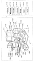
- FIG. 1 is a diagram showing a configuration example of an X-ray fluoroscopic apparatus according to the present invention.
- the X-ray fluoroscopic apparatus shown in FIG. 1 includes a top plate 102 on which a subject 101 is placed, an X-ray source 103 that irradiates the subject 101 with X-rays, and an X-ray diaphragm that sets an X-ray irradiation area for the subject 101
- An X-ray detector 105a including an apparatus 104, an X-ray detector 105a that detects X-rays irradiated from the X-ray source 103 and transmitted through the subject 101, an X-ray source 103 and an X-ray diaphragm device 104,
- a support device 106 that supports and detects the X-ray source 103 and the X-ray diaphragm device 104 by supporting and moving the support device 106.
- the detection unit 105 is rotated in a direction with the longitudinal direction of the top plate 102 (hereinafter referred to as the X direction) as an axis, and the rotation of the top plate 102 in a direction with the short direction (hereinafter referred to as the Y direction) as an axis.
- Support device moving mechanism 120 that slides in the X direction, and the top plate 102, the top plate 102 is moved vertically in the direction perpendicular to the floor surface 1 (hereinafter Z direction), and the Y direction
- the top plate is moved to slide A mechanism 110, a top plate tilting mechanism 111 that erects the top plate 102 with respect to the floor surface 1 while maintaining the relative positions of the top plate 102, the X-ray source 103, the X-ray diaphragm device 104, and the X-ray detection unit 105;
- a support column 112 standing on the floor 1 and supporting the top plate tilting mechanism 111, an X-ray source 103, an X-ray diaphragm device 104, and an X-ray detection unit 105 moved by the support moving mechanism 120 and the top plate moving mechanism 110.
- a position detector 113 for detecting the positional relationship between the top plate 102, a high voltage generator 114 for supplying power to the X-ray source 103, and image processing on the X-ray signal output from the X-ray detector 105a.
- a control unit 118 that controls the elements and an operation unit 119 that gives commands to the control unit 118 are provided.
- the XYZ directions are orthogonal to each other.
- the X-ray source 103 has an X-ray tube that receives power supply from the high voltage generator 114 and generates X-rays. Further, the X-ray source 103 may have an X-ray filter that selectively transmits X-rays having specific energy.
- the X-ray diaphragm device 104 has a plurality of lead plates for shielding X-rays generated from the X-ray source 103, and irradiates the subject 101 by moving the plurality of lead plates for shielding X-rays, respectively. Determine the X-ray irradiation area.
- the X-ray detector 105 includes an X-ray detector 105a, an X-ray detector moving mechanism 105b, and an X-ray detector distance measurement sensor 105c.
- the X-ray detector 105a includes, for example, a plurality of X-ray detectors.
- the detection elements are arranged in a two-dimensional array, and are devices that detect an X-ray signal corresponding to an incident amount of X-rays irradiated from the X-ray source 103 and transmitted through the subject 101.
- the X-ray detector moving mechanism 105b changes the distance from the X-ray source 103 by moving the position of the X-ray detector 105a.
- the X-ray detector moving mechanism 105b Next, the position of the X-ray detector 105a is moved. The position of the X-ray detector 105a moved by the X-ray detector moving mechanism 105b is detected by the position detector 113.
- the moving mechanism of the X-ray detector 105a is implemented by a known technique such as a rack and pinion.
- the X-ray detector distance measurement sensor 105c prevents, for example, a collision between the X-ray detector 105a and the subject 101 on the top plate 102 when the X-ray detector 105a is moved by the X-ray detector moving mechanism 105b. Sensor for measuring the distance to an object approaching the X-ray detector 105a.
- the X-ray detector distance measuring sensor 105c is configured by, for example, infrared rays or ultrasonic waves. The value measured by the X-ray detector distance measuring sensor 105c is transmitted to the control unit 118. Further, it goes without saying that the X-ray detector distance measuring sensor 105c also operates when the X-ray detector 105a moves in accordance with the movement of the support 106 described later.
- the support device 106 has a C shape, and an X-ray source 103 and an X-ray diaphragm device 104 are set at one end of the support device 106, and an X-ray detection unit 105 is set at the other end.
- the shape of the support device 106 is not limited to a C shape, and may be any shape as long as the X-ray source 103 and the X-ray diaphragm device 104 and the X-ray detection unit 105 can be arranged to face each other with the top plate 102 interposed therebetween.
- the support device moving mechanism 120 includes a support device rotation mechanism 107, a support device rotation mechanism 108, and a support device slide mechanism 109.
- the support device rotation mechanism 107 supports the support device 106, and includes an X-ray source 103 and an X-ray diaphragm.
- the device 104 and the X-ray detection unit 105 are rotated about the X direction, and the support device rotation mechanism 108 supports the support device rotation mechanism 107, and the X-ray source 103 and the X-ray diaphragm device 104
- the X-ray detection unit 105 is rotated about the Y direction.
- the support slide mechanism 109 includes a slide rail 109b extending in the X direction, and a slide mechanism 109A that runs on the slide rail 109b and supports the support rotation mechanism 108, and includes an X-ray source 103 and an X-ray diaphragm.
- the apparatus 104 and the X-ray detection unit 105 are slid in the X direction. That is, the X-ray source 103, the X-ray diaphragm 104, and the X-ray detector 105 can be slid along the body axis direction of the subject 101 on the top plate 102.
- the top plate moving mechanism 110 includes a top plate vertical moving mechanism 110A and a top plate horizontal moving mechanism 110b.
- the top plate vertical moving mechanism 110A is installed at the end of the slide mechanism 109A and moves the top plate 102 in the Z direction. It is a mechanism to move to.
- the top plate horizontal movement mechanism 110b is a mechanism that is supported by the top plate vertical movement mechanism 110A and moves the top plate 102 in the Y direction.
- the image processing unit 115 performs image processing on the X-ray signal output from the X-ray detector 105a, and outputs an image-processed X-ray image.
- Image processing includes gamma conversion, gradation conversion processing, image enlargement / reduction, and the like.
- the image processed by the image processing unit 115 is output to the image storage unit 116 and the display device 117.
- the display device 117 displays various images stored in the image storage unit 116 in addition to the various images output from the image processing unit 115.
- the operation unit 119 includes a keyboard, a mouse, a joystick, and the like, and instructs the control unit 118.
- FIG. 2 is a diagram for explaining types of positional relationships among the X-ray source 103, the X-ray diaphragm device 104, the X-ray detection unit 105, and the top plate 102 in the X-ray fluoroscopic apparatus shown in FIG. It is.
- FIG. 3 shows an X-ray source 103 and an X-ray diaphragm device 104 for obtaining a fluoroscopic image in the body axis direction for the subject 101 on the top plate 102 in the X-ray fluoroscopic apparatus shown in FIG.
- FIG. 6 is a diagram for explaining an operation with the X-ray detection unit 105.
- FIG. 3 shows an X-ray source 103 and an X-ray diaphragm device 104 for obtaining a fluoroscopic image in the body axis direction for the subject 101 on the top plate 102 in the X-ray fluoroscopic apparatus shown in FIG.
- FIG. 6 is a diagram for explaining an operation with the X-ray detection unit 105
- FIG. 4 is a diagram for explaining the operation of the X-ray detection unit 105 when acquiring a fluoroscopic image and a captured image.
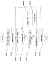
- FIG. 5 is a flowchart for explaining the present embodiment.
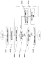
- FIG. 10 is a functional block diagram for explaining the present embodiment.
- FIG. 2 (a) simply shows the positional relationship between the X-ray source 103 and the X-ray diaphragm device 104, the X-ray detection unit 105, and the top plate 102 shown in FIG.
- An X-ray source 103 and an X-ray diaphragm device 104 are disposed on the back surface side, and an X-ray detection unit 105 is disposed on the surface of the top plate 102 (surface on which the subject 101 is disposed). This arrangement is called an undertube.
- FIG. 2 (b) shows the back side of the top plate 102 by rotating the X-ray source 103, the X-ray diaphragm device 104, and the X-ray detection unit 105 around the X direction by the support rotating mechanism 107.
- the X-ray detection unit 105 is disposed on the surface, and the X-ray source 103 and the X-ray diaphragm device 104 are disposed on the surface. This arrangement is called an overtube.
- this embodiment will be described in detail using the case of an undertube.
- the operator uses the operation unit 119 to instruct the control unit 118 to acquire the fluoroscopic image. Do. Based on the command, the control unit 118 slides the X-ray source 103, the X-ray diaphragm device 104, and the X-ray detection unit 105 in the body axis direction of the subject 101 using the support slide mechanism 109.
- the X-ray dose irradiated to the subject 101 is smaller than that at the time of acquiring a captured image described later. This is for grasping the photographing position when acquiring a photographed image for viewing the region of interest of the subject 101 in more detail.
- the X-ray dose required for grasping the position is limited to the subject. 101 exposure reduction.
- the X-ray dose is performed by controlling the output of the high voltage generator 114 that supplies power to the X-ray source 103.
- the output value of the high voltage generator 114 can be arbitrarily set within a predetermined range using a value set in the control unit 118 in advance or the operation unit 119 by the operator.
- a fluoroscopic image of the subject 101 is acquired from point A to point C.
- the operator can use the display device 117 to see the fluoroscopic image.
- the operator uses the perspective image displayed on the display device 117 to specify the region of interest of the subject 101 for which a captured image is to be acquired.
- the region of interest is point B
- the operator uses the operation unit 119 to instruct the control unit 118 to acquire a captured image.
- the control unit 118 causes the X-ray detector moving mechanism 105b to bring the X-ray detector 105a close to the vicinity of the subject 101 and then performs imaging. This will be described in more detail with reference to FIGS. 4 and 5.
- the diagram shown in FIG. 4 (a) shows details of the positional relationship among the X-ray source 103, the X-ray diaphragm 104, the X-ray detector 105, and the subject 101 at the time of obtaining a fluoroscopic image at the point B.
- the distance between the X-ray source 103 and the X-ray detection unit 105 is L1
- the distance from the X-ray detection unit 105, more specifically, the X-ray detector 105a to the front part of the body of the subject 101 is L2.
- the diagram shown in FIG. 4 (b) shows the details of each positional relationship when a captured image is acquired at the point B.
- the control unit 118 that has received an imaging image acquisition command from the operator at the point B causes the X-ray detector moving mechanism 105b to bring the X-ray detector 105a close to the vicinity of the subject 101, and from the X-ray detector 105a to the subject 101. Reduce the distance to the body surface from L2 to L4. The distance between the X-ray source 103 and the X-ray detector 105 is shortened from L1 to L3. There is no change in the positional relationship between the subject 101 and the X-ray source 103.
- control unit 118 uses the value measured by the X-ray detector distance measurement sensor 105c to make the X-ray detector 105a as far as possible. It is close to the vicinity of 101.
- the purpose of acquiring the fluoroscopic image is to grasp the captured image acquisition position, so it is sufficient if an image having a certain level of image quality can be acquired. Therefore, when obtaining a fluoroscopic image, the object is examined using the support slide mechanism 109 while the distances between the X-ray source 103 and the X-ray diaphragm device 104, the X-ray detection unit 105, and the top plate 102 are kept constant. 101 slides in the body axis direction. If a high-quality image is acquired by minimizing the magnification rate even when acquiring a fluoroscopic image, it is necessary to move the position of the X-ray detector 105a sequentially along the unevenness of the body surface of the subject 101. Therefore, very complicated control is required, and traveling time is also required.
- step S501 the operator moves the X-ray source 103, the X-ray diaphragm device 104, and the X-ray detection unit 105 to the fluoroscopic image acquisition start position using the support movement switch 1001 provided in the operation unit 119.
- step S502 the operator uses the fluoroscopic image acquisition start switch 1002 provided in the operation unit 119 to start irradiating the subject 101 with a preset X-ray dose from the X-ray tube 103.
- step S503 the operator starts sliding movement of the X-ray source 103, the X-ray diaphragm device 104, and the X-ray detection unit 105 in the body axis direction of the subject 101 using the support movement switch 1001. .
- the operator can also use the supporter movement switch 1001 to pause the slide movement.
- step S504 the operator determines whether or not it is a desired shooting position from the fluoroscopic image displayed on the display device 117. If it is determined that the photographing position is desired, the process proceeds to step S505, and if not, the process proceeds to step S507 described later.
- step S505 the operator uses the supporter movement switch 1001 to stop the slide movement and presses the captured image acquisition switch 1003 provided in the operation unit 119.
- step S506 the control unit 118 uses the X-ray detector moving mechanism 105b and the X-ray detector distance measurement sensor 105c to perform imaging by bringing the X-ray detector 105a close to the vicinity of the subject 101, and ends the imaging. Thereafter, the X-ray detector 105a is returned to the original position, and the slide movement by the supporter movement switch 1001 is made possible again. Whether or not the slide movement by the supporter movement switch 1001 is valid is notified to the operator by turning on and off a display lamp (not shown) provided in the operation unit 119.
- step S506 After step S506 ends, the process returns to step S503.
- step S507 the operator determines whether or not the X-ray source 103, the X-ray diaphragm device 104, and the X-ray detection unit 105 have reached the fluoroscopic image acquisition end position. If it has reached the fluoroscopic image acquisition end position, the process proceeds to step S508; otherwise, the process returns to step S503.
- step S508 the operator ends fluoroscopy using the fluoroscopic image acquisition end switch 1004 provided in the operation unit 119.
- the operator when acquiring a captured image with a reduced magnification of the subject 101, the operator can use the fluoroscopic image of the subject 101 displayed on the display device 117.
- the control unit 118 uses the X-ray detector moving mechanism 105b and the X-ray detector distance measurement sensor 105c to move the X-ray detector 105a to the vicinity of the subject 101 and perform imaging. Therefore, the operator can easily obtain a high-quality captured image with a reduced magnification.
- the fluoroscopic image is acquired in the body axis direction of the subject 101 with the undertube.
- the X-ray source 103, the X-ray diaphragm device 104, and the X-ray detection when acquiring the fluoroscopic image are described.
- the arrangement position and moving direction of the unit 105 can be implemented without any particular limitation.
- the present invention can be implemented even in the case of an overtube or when the periphery of the subject 101 is seen through with the X direction as the rotation axis.
- the operator moves the X-ray source 103, the X-ray aperture device 104, and the X-ray detection unit 105 in the body axis direction of the subject 101 by using the support moving switch 1001, and acquires a fluoroscopic image.
- the control unit 118 may perform sliding movement. In this case, the process related to shooting by the operator is interrupted with respect to the slide movement by the control unit 118. As a result, it is not necessary to operate the supporter movement switch 1001 during slide movement when acquiring a fluoroscopic image, so that the burden on the operator is reduced.
- Example 2 of the present invention will be described with reference to FIGS. Further, differences from the first embodiment will be described.
- FIG. 6 is a diagram for explaining the operation of the X-ray fluoroscopic apparatus when there are a plurality of regions of interest for which a captured image is to be acquired.
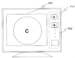
- FIG. 7 is a view showing an example of a shooting reservation screen displayed on the display device 117.
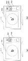
- FIG. 8 is a diagram illustrating an example of a display screen displayed on the display device 117 when shooting is performed based on a shooting reservation.
- FIG. 9 is a flowchart for explaining the present embodiment.
- FIG. 6 (a) is the same diagram as FIG. 3, and is a diagram in which a fluoroscopic image is acquired from point A to point C in the body axis direction of the subject 101.
- FIG. The X-ray fluoroscopic apparatus of the present embodiment is particularly effective when there are a plurality of places where it is determined that the operator wants to acquire a captured image.
- the operator performs a fluoroscopy from the point A to the point C in the body axis direction of the subject 101, and at this time, the radiographed image of the subject 101 displayed on the display device 117 is seen to be a captured image.
- the position is memorized by using the photographing reservation function at the point where it is determined that the image acquisition is desired, and the photographing reservation is performed.
- the positions of the X-ray source 103, the X-ray diaphragm device 104, and the X-ray detection unit 105 are detected by the position detection unit 113.
- the imaging reservation is performed by the operator using the operation unit 119, and the perspective image of the reserved point is reduced to the side of the currently acquired fluoroscopic image 701 and displayed as the imaging reservation image 702 as shown in FIG.
- the operator can grasp the reserved shooting position and the number of shots by looking at the shooting reservation image 702.
- the control unit 118 starts photographing based on the photographing reservation.
- FIG. 6B shows the operation of the X-ray source 103, the X-ray diaphragm device 104, and the X-ray detection unit 105 when the imaging reservation points are the points A and B. Since the operations of the X-ray detector 105a and the like at the time of imaging are the same as those in the first embodiment, description thereof is omitted.
- the control unit 118 displays on the display device 117 as shown in FIG.
- the shooting start display 801 is flashed around the reserved shooting image 702 at the point B with a red frame or the like.
- the control unit 118 performs imaging by operating the X-ray detector 105a and the like in the same manner as in the first embodiment.
- the control unit 118 displays the acquired captured image 802 on the display device 117, and further replaces the reserved shooting image displayed on the display device 117 with a reduced captured image 803 obtained by reducing the captured image 802. To display.
- a photographing end display 804 is displayed around the reduced photographed image 803 with a blue frame line or the like.
- the shooting start display 801 and the shooting end display 804 are displayed by frame lines, but the present invention is not limited to this.
- the reduced photographed image 803 may be displayed using a mark or the like.
- step S905 the operator presses a photographing image reservation switch (not shown) provided in the operation unit 119 to make a photographing reservation.
- step S906 the control unit 118 displays the currently acquired fluoroscopic image 701 on which the imaging reservation has been made on the display device 117 as the imaging reservation image 702.
- step S909 the control unit 118 starts shooting based on the shooting reservation.
- the acquired photographic image is displayed on the display device 117, and a reduced photographic image 803 obtained by reducing the photographic image is displayed.
- a display indicating the end of shooting is displayed on the display device 117.
- the operator when acquiring captured images with a reduced magnification rate of the subject 101 at a plurality of locations, the operator can display the subject 101 displayed on the display device 117. Since the control unit 118 sequentially acquires captured images based on the reserved imaging simply by making a reservation for imaging from the fluoroscopic image, the operator can easily acquire high-quality captured images with reduced magnification at multiple locations. Can do.
- the arrangement positions and moving directions of the X-ray source 103, the X-ray diaphragm device 104, and the X-ray detection unit 105 when acquiring a fluoroscopic image are not particularly limited. Further, regarding the movement operation of the X-ray source 103, the X-ray diaphragm device 104, and the X-ray detection unit 105, similarly to the first embodiment, after the operator has previously set the fluoroscopic image acquisition start position and the fluoroscopic image acquisition end position, The slide may be performed by the control unit 118.
Landscapes
- Health & Medical Sciences (AREA)
- Life Sciences & Earth Sciences (AREA)
- Medical Informatics (AREA)
- Engineering & Computer Science (AREA)
- Radiology & Medical Imaging (AREA)
- Biomedical Technology (AREA)
- Biophysics (AREA)
- Nuclear Medicine, Radiotherapy & Molecular Imaging (AREA)
- Optics & Photonics (AREA)
- Pathology (AREA)
- Physics & Mathematics (AREA)
- High Energy & Nuclear Physics (AREA)
- Heart & Thoracic Surgery (AREA)
- Molecular Biology (AREA)
- Surgery (AREA)
- Animal Behavior & Ethology (AREA)
- General Health & Medical Sciences (AREA)
- Public Health (AREA)
- Veterinary Medicine (AREA)
- Apparatus For Radiation Diagnosis (AREA)
Abstract
L'invention porte sur un dispositif fluoroscopique à rayons-X et sur un procédé fluoroscopique à rayons-X qui permettent de positionner plus facilement un détecteur de rayons-X et ainsi d'obtenir plus facilement une image photographiée dont le facteur de grossissement est réduit lorsque l'image photographiée est obtenue. L'image photographiée d'un sujet est obtenue sur la base d'une image transparente du sujet affichée sur un dispositif d'affichage à l'aide d'un mécanisme de déplacement de détecteur de rayons-X disposé sur une unité de détection de rayons-X et conçu pour faire varier la distance par rapport à une source de rayons-X, et d'un capteur de mesure de distance de détecteur de rayons-X pour empêcher une collision avec le détecteur de rayons-X. le détecteur de rayons-X est déplacé par un dispositif de commande à proximité du sujet afin d'obtenir une image photographiée dont le facteur de grossissement est réduit par rapport à l'image transparente.
Priority Applications (2)
| Application Number | Priority Date | Filing Date | Title |
|---|---|---|---|
| CN201180049340.8A CN103167832B (zh) | 2010-10-14 | 2011-10-13 | X射线透视摄影装置以及x射线透视摄影方法 |
| JP2012538706A JP5943351B2 (ja) | 2010-10-14 | 2011-10-13 | X線透視撮影装置及びx線透視撮影方法 |
Applications Claiming Priority (2)
| Application Number | Priority Date | Filing Date | Title |
|---|---|---|---|
| JP2010-231196 | 2010-10-14 | ||
| JP2010231196 | 2010-10-14 |
Publications (1)
| Publication Number | Publication Date |
|---|---|
| WO2012050148A1 true WO2012050148A1 (fr) | 2012-04-19 |
Family
ID=45938372
Family Applications (1)
| Application Number | Title | Priority Date | Filing Date |
|---|---|---|---|
| PCT/JP2011/073472 Ceased WO2012050148A1 (fr) | 2010-10-14 | 2011-10-13 | Dispositif et procédé fluoroscopiques à rayons-x |
Country Status (3)
| Country | Link |
|---|---|
| JP (1) | JP5943351B2 (fr) |
| CN (1) | CN103167832B (fr) |
| WO (1) | WO2012050148A1 (fr) |
Families Citing this family (2)
| Publication number | Priority date | Publication date | Assignee | Title |
|---|---|---|---|---|
| EP2873403A1 (fr) * | 2013-11-18 | 2015-05-20 | Ondal Medical Systems GmbH | Dispositif à pied avec surveillance anti collision et procédé de surveillance anti collision |
| JP6610795B2 (ja) * | 2016-08-29 | 2019-11-27 | 株式会社島津製作所 | X線撮影装置用保持機構およびx線撮影装置 |
Citations (6)
| Publication number | Priority date | Publication date | Assignee | Title |
|---|---|---|---|---|
| JPS58218949A (ja) * | 1982-06-15 | 1983-12-20 | 株式会社東芝 | X線透視撮影装置 |
| JPH09276259A (ja) * | 1996-02-16 | 1997-10-28 | Toshiba Corp | X線診断装置 |
| JP2001095790A (ja) * | 1999-09-30 | 2001-04-10 | Shimadzu Corp | X線透視撮影装置 |
| JP2005510278A (ja) * | 2001-11-23 | 2005-04-21 | ジーイー・メディカル・システムズ・グローバル・テクノロジー・カンパニー・エルエルシー | X線源・画像間の可変距離を利用した3d再構成システム及び方法 |
| JP2005245502A (ja) * | 2004-03-01 | 2005-09-15 | Toshiba Corp | X線画像診断装置 |
| JP2010162175A (ja) * | 2009-01-16 | 2010-07-29 | Hitachi Medical Corp | X線装置 |
-
2011
- 2011-10-13 WO PCT/JP2011/073472 patent/WO2012050148A1/fr not_active Ceased
- 2011-10-13 CN CN201180049340.8A patent/CN103167832B/zh not_active Expired - Fee Related
- 2011-10-13 JP JP2012538706A patent/JP5943351B2/ja active Active
Patent Citations (6)
| Publication number | Priority date | Publication date | Assignee | Title |
|---|---|---|---|---|
| JPS58218949A (ja) * | 1982-06-15 | 1983-12-20 | 株式会社東芝 | X線透視撮影装置 |
| JPH09276259A (ja) * | 1996-02-16 | 1997-10-28 | Toshiba Corp | X線診断装置 |
| JP2001095790A (ja) * | 1999-09-30 | 2001-04-10 | Shimadzu Corp | X線透視撮影装置 |
| JP2005510278A (ja) * | 2001-11-23 | 2005-04-21 | ジーイー・メディカル・システムズ・グローバル・テクノロジー・カンパニー・エルエルシー | X線源・画像間の可変距離を利用した3d再構成システム及び方法 |
| JP2005245502A (ja) * | 2004-03-01 | 2005-09-15 | Toshiba Corp | X線画像診断装置 |
| JP2010162175A (ja) * | 2009-01-16 | 2010-07-29 | Hitachi Medical Corp | X線装置 |
Also Published As
| Publication number | Publication date |
|---|---|
| CN103167832A (zh) | 2013-06-19 |
| JPWO2012050148A1 (ja) | 2014-02-24 |
| JP5943351B2 (ja) | 2016-07-05 |
| CN103167832B (zh) | 2016-10-12 |
Similar Documents
| Publication | Publication Date | Title |
|---|---|---|
| US8351568B2 (en) | Long length multiple detector imaging apparatus and method | |
| JP5579636B2 (ja) | 放射線画像撮影装置および放射線画像撮影方法 | |
| CN102440079B (zh) | X射线摄影装置 | |
| JP6658578B2 (ja) | X線撮影装置 | |
| JP2009225945A (ja) | 放射線長尺撮影における撮影支援装置 | |
| JP5702236B2 (ja) | X線撮影装置およびそのキャリブレーション方法 | |
| JP5550209B2 (ja) | X線撮影装置 | |
| JP5279672B2 (ja) | 放射線撮影システム及びその撮影制御方法 | |
| JP2011072346A (ja) | X線画像撮影装置、撮影方法および撮影プログラム | |
| WO2014132361A1 (fr) | Dispositif d'imagerie par rayons x | |
| JP2022068290A (ja) | X線透視撮影装置およびx線透視撮影システム | |
| JP5943351B2 (ja) | X線透視撮影装置及びx線透視撮影方法 | |
| JP5553965B2 (ja) | 放射線画像撮影システム | |
| JP2012075798A (ja) | 放射線撮影装置、放射線撮影システム、画像処理装置及びプログラム | |
| JP6540827B2 (ja) | 放射線撮影装置 | |
| JP5049836B2 (ja) | 放射線撮影方法 | |
| JP5959972B2 (ja) | X線診断装置 | |
| EP4268723B1 (fr) | Dispositif radiographique et procédé radiographique l'utilisant | |
| JP2015112298A5 (fr) | ||
| JP2015112298A (ja) | X線画像診断装置 | |
| JP2012161472A (ja) | 放射線画像撮影装置および放射線画像撮影方法 | |
| JP5259061B2 (ja) | 医用画像撮影装置 | |
| JP2023183893A (ja) | X線撮影システム、x線撮影方法、x線撮影制御装置及びプログラム | |
| US20260096798A1 (en) | X-ray imaging apparatus | |
| JP2017006595A (ja) | 画像処理装置、断層画像生成システム及びプログラム |
Legal Events
| Date | Code | Title | Description |
|---|---|---|---|
| 121 | Ep: the epo has been informed by wipo that ep was designated in this application |
Ref document number: 11832580 Country of ref document: EP Kind code of ref document: A1 |
|
| ENP | Entry into the national phase |
Ref document number: 2012538706 Country of ref document: JP Kind code of ref document: A |
|
| NENP | Non-entry into the national phase |
Ref country code: DE |
|
| 122 | Ep: pct application non-entry in european phase |
Ref document number: 11832580 Country of ref document: EP Kind code of ref document: A1 |