WO2012053025A1 - 鉛蓄電池 - Google Patents
鉛蓄電池 Download PDFInfo
- Publication number
- WO2012053025A1 WO2012053025A1 PCT/JP2010/006154 JP2010006154W WO2012053025A1 WO 2012053025 A1 WO2012053025 A1 WO 2012053025A1 JP 2010006154 W JP2010006154 W JP 2010006154W WO 2012053025 A1 WO2012053025 A1 WO 2012053025A1
- Authority
- WO
- WIPO (PCT)
- Prior art keywords
- bone
- lattice
- bones
- thickness direction
- thickness
- Prior art date
- Legal status (The legal status is an assumption and is not a legal conclusion. Google has not performed a legal analysis and makes no representation as to the accuracy of the status listed.)
- Ceased
Links
Images




Classifications
-
- H—ELECTRICITY
- H01—ELECTRIC ELEMENTS
- H01M—PROCESSES OR MEANS, e.g. BATTERIES, FOR THE DIRECT CONVERSION OF CHEMICAL ENERGY INTO ELECTRICAL ENERGY
- H01M4/00—Electrodes
- H01M4/02—Electrodes composed of, or comprising, active material
- H01M4/64—Carriers or collectors
- H01M4/70—Carriers or collectors characterised by shape or form
- H01M4/72—Grids
- H01M4/73—Grids for lead-acid accumulators, e.g. frame plates
-
- H—ELECTRICITY
- H01—ELECTRIC ELEMENTS
- H01M—PROCESSES OR MEANS, e.g. BATTERIES, FOR THE DIRECT CONVERSION OF CHEMICAL ENERGY INTO ELECTRICAL ENERGY
- H01M10/00—Secondary cells; Manufacture thereof
- H01M10/06—Lead-acid accumulators
- H01M10/12—Construction or manufacture
-
- H—ELECTRICITY
- H01—ELECTRIC ELEMENTS
- H01M—PROCESSES OR MEANS, e.g. BATTERIES, FOR THE DIRECT CONVERSION OF CHEMICAL ENERGY INTO ELECTRICAL ENERGY
- H01M4/00—Electrodes
- H01M4/02—Electrodes composed of, or comprising, active material
- H01M4/14—Electrodes for lead-acid accumulators
- H01M4/16—Processes of manufacture
- H01M4/20—Processes of manufacture of pasted electrodes
-
- H—ELECTRICITY
- H01—ELECTRIC ELEMENTS
- H01M—PROCESSES OR MEANS, e.g. BATTERIES, FOR THE DIRECT CONVERSION OF CHEMICAL ENERGY INTO ELECTRICAL ENERGY
- H01M4/00—Electrodes
- H01M4/86—Inert electrodes with catalytic activity, e.g. for fuel cells
- H01M4/88—Processes of manufacture
- H01M4/8875—Methods for shaping the electrode into free-standing bodies, like sheets, films or grids, e.g. moulding, hot-pressing, casting without support, extrusion without support
-
- H—ELECTRICITY
- H01—ELECTRIC ELEMENTS
- H01M—PROCESSES OR MEANS, e.g. BATTERIES, FOR THE DIRECT CONVERSION OF CHEMICAL ENERGY INTO ELECTRICAL ENERGY
- H01M2220/00—Batteries for particular applications
- H01M2220/20—Batteries in motive systems, e.g. vehicle, ship, plane
-
- Y—GENERAL TAGGING OF NEW TECHNOLOGICAL DEVELOPMENTS; GENERAL TAGGING OF CROSS-SECTIONAL TECHNOLOGIES SPANNING OVER SEVERAL SECTIONS OF THE IPC; TECHNICAL SUBJECTS COVERED BY FORMER USPC CROSS-REFERENCE ART COLLECTIONS [XRACs] AND DIGESTS
- Y02—TECHNOLOGIES OR APPLICATIONS FOR MITIGATION OR ADAPTATION AGAINST CLIMATE CHANGE
- Y02E—REDUCTION OF GREENHOUSE GAS [GHG] EMISSIONS, RELATED TO ENERGY GENERATION, TRANSMISSION OR DISTRIBUTION
- Y02E60/00—Enabling technologies; Technologies with a potential or indirect contribution to GHG emissions mitigation
- Y02E60/10—Energy storage using batteries
-
- Y—GENERAL TAGGING OF NEW TECHNOLOGICAL DEVELOPMENTS; GENERAL TAGGING OF CROSS-SECTIONAL TECHNOLOGIES SPANNING OVER SEVERAL SECTIONS OF THE IPC; TECHNICAL SUBJECTS COVERED BY FORMER USPC CROSS-REFERENCE ART COLLECTIONS [XRACs] AND DIGESTS
- Y02—TECHNOLOGIES OR APPLICATIONS FOR MITIGATION OR ADAPTATION AGAINST CLIMATE CHANGE
- Y02E—REDUCTION OF GREENHOUSE GAS [GHG] EMISSIONS, RELATED TO ENERGY GENERATION, TRANSMISSION OR DISTRIBUTION
- Y02E60/00—Enabling technologies; Technologies with a potential or indirect contribution to GHG emissions mitigation
- Y02E60/30—Hydrogen technology
- Y02E60/50—Fuel cells
-
- Y—GENERAL TAGGING OF NEW TECHNOLOGICAL DEVELOPMENTS; GENERAL TAGGING OF CROSS-SECTIONAL TECHNOLOGIES SPANNING OVER SEVERAL SECTIONS OF THE IPC; TECHNICAL SUBJECTS COVERED BY FORMER USPC CROSS-REFERENCE ART COLLECTIONS [XRACs] AND DIGESTS
- Y02—TECHNOLOGIES OR APPLICATIONS FOR MITIGATION OR ADAPTATION AGAINST CLIMATE CHANGE
- Y02P—CLIMATE CHANGE MITIGATION TECHNOLOGIES IN THE PRODUCTION OR PROCESSING OF GOODS
- Y02P70/00—Climate change mitigation technologies in the production process for final industrial or consumer products
- Y02P70/50—Manufacturing or production processes characterised by the final manufactured product
-
- Y—GENERAL TAGGING OF NEW TECHNOLOGICAL DEVELOPMENTS; GENERAL TAGGING OF CROSS-SECTIONAL TECHNOLOGIES SPANNING OVER SEVERAL SECTIONS OF THE IPC; TECHNICAL SUBJECTS COVERED BY FORMER USPC CROSS-REFERENCE ART COLLECTIONS [XRACs] AND DIGESTS
- Y02—TECHNOLOGIES OR APPLICATIONS FOR MITIGATION OR ADAPTATION AGAINST CLIMATE CHANGE
- Y02T—CLIMATE CHANGE MITIGATION TECHNOLOGIES RELATED TO TRANSPORTATION
- Y02T10/00—Road transport of goods or passengers
- Y02T10/60—Other road transportation technologies with climate change mitigation effect
- Y02T10/70—Energy storage systems for electromobility, e.g. batteries
Definitions
- the present invention relates to a lead storage battery.
- lithium-ion batteries and nickel-metal hydride batteries are disadvantageous in terms of price.
- lithium-ion batteries need to be considered in terms of safety, so they can be used in office buildings and hospitals in preparation for power outages.
- Lead-acid batteries are often used as batteries used for backup power supplies to be installed, industrial batteries for measures against instantaneous voltage drop, or automobile batteries.
- power generation facilities using natural energy such as power generation facilities using solar cells and wind power generators, have been actively built. In such power generation facilities, In order to level the power, it has been studied to attach a power storage facility using a secondary battery to the power generation facility. Since such a power storage facility requires a large amount of batteries, it is advantageous to use a lead storage battery as the battery.
- a lead storage battery has a structure in which an electrode plate group configured by laminating a positive electrode plate and a negative electrode plate via a separator is housed in a battery case together with an electrolytic solution.
- the electrode plate of the lead storage battery those having various structures such as a clad type, a paste type, and a tudor type are known.
- a paste capable of discharging a large current is used in a lead storage battery for industrial use or automobile.
- a paste capable of discharging a large current is used.
- Many types of electrode plates are used.
- sealed lead batteries that eliminate the need for water replenishment are often used to facilitate maintenance.
- the life of a lead storage battery is equivalent to the service life of a power generation means such as a wind power generator or a solar cell (for example, 17 years or more). It is hoped to do.
- the paste-type positive electrode plate and negative electrode plate have a structure in which a positive electrode active material and a negative electrode active material constituting the current collector are filled with a positive electrode active material and a negative electrode active material, respectively, and held.
- the positive electrode grid plate and the negative electrode grid plate are produced by casting and those produced by subjecting a lead or lead alloy plate to expansion processing, but the battery life is extended. As described later, since it is necessary to increase the cross-sectional area of the lattice bone, it is necessary to use a positive electrode lattice plate and a negative electrode lattice plate manufactured by casting. It is advantageous.
- a lattice plate manufactured by casting has a substantially quadrangular (rectangular or square) outline shape as shown in, for example, Patent Document 1, extends in the horizontal direction, and is a pair of horizontal frames facing the vertical direction.
- a frame portion having a bone and a pair of vertical frame bones extending in the vertical direction and opposed in the horizontal direction; a plurality of horizontal lattice bones and a plurality of vertical lattice bones forming a lattice inside the frame portion; and the frame portion Current collecting ears formed integrally with one of the lateral frame bones.
- the part of the grid plate provided with the current collecting ears is the upper part of the grid plate, and the direction in which the vertical frame bone extends (longitudinal)
- the longitudinal direction of the frame bone is defined as the longitudinal direction of the lattice plate.
- the direction in which the lateral frame bone extends is the lateral direction of the lattice plate, and the direction perpendicular to both the longitudinal direction and the lateral direction of the lattice plate is the thickness direction of the lattice plate.
- the vertical direction, the horizontal direction, and the thickness direction of the electrode plate are directions along the vertical direction, the horizontal direction, and the thickness direction of the lattice plate, respectively.
- the direction along the thickness direction of the lattice plate is the thickness direction, and the direction perpendicular to both the longitudinal direction and the thickness direction is the width direction. Further, when the lattice plate is placed on a horizontal plane and filled with the active material, the surface directed upward and the surface directed downward are defined as the front and back surfaces of the lattice plate, respectively.
- paste is filled with the lattice plates laid down (with the thickness direction oriented vertically).
- the paste-like active material is supplied to the surface of the lattice plate from above, and the supplied active material is passed through the lattice from the surface of the lattice plate (the surface facing upward of the lattice plate) to the back surface (below the lattice plate).
- the active material is filled in the entire lattice by making it flow toward the surface).
- the horizontal lattice bone and the entire vertical lattice bone of the lattice plate are embedded in the active material.
- the portion of the lattice bone exposed from the active material (referred to as the exposed portion of the lattice bone) is in direct contact with sulfuric acid that is the electrolyte. Therefore, a discharge reaction occurs on the surface of the exposed portion of the lattice bone during discharge, and a passive lead sulfate (PbSO4) film is generated on the surface of the exposed portion of the lattice bone.
- PbSO4 passive lead sulfate
- the lattice bone when the lattice bone is formed of a lead alloy containing calcium, the surface of the lattice bone is active, so if the surface of the lattice bone is in direct contact with the electrolyte, the discharge reaction occurs on the surface of the lattice bone. This leads to the formation of a lead sulfate film.
- the passive film formed on the surface of the lattice bone does not have conductivity and will not return to its original state when charged. If a part of the lattice bone of the grid plate for the positive electrode is exposed from the active material, the electrolyte enters the interface between the lattice bone and the active material from the exposed portion, so that the surface of the lattice bone is not exposed. The generation of the dynamic membrane progresses, and eventually the passive membrane is generated on the entire surface of the lattice bone. When a passive film is formed on the entire surface of the lattice bone, conduction between the lattice bone and the active material is hindered, so that charging cannot be performed, and the battery has an early capacity drop (PCL). : Premature Capacity Loss), and it becomes impossible to meet the demand for longer battery life.
- PCL early capacity drop
- lead-acid batteries will eventually reach the end of their life as their parts deteriorate with use.
- the main cause of lead-acid batteries reaching the end of their life is the corrosion of the grid plate (generation of PbO2 due to oxidation) that occurs on the positive electrode plate during charging.
- the generation of PbO2 on the positive electrode grid plate gradually progresses from the surface of the grid plate to the inside thereof.
- PbO2 has conductivity, but because it is fragile, when the lattice bone progresses, the lattice bone breaks or the shape of the lattice bone collapses and the function of holding the active material is lost.
- the battery will eventually reach the end of its life.
- the gaps between the lattice bones are narrowed. Therefore, an amount of active material necessary for obtaining a predetermined battery capacity is added to the lattice plates. Can no longer be filled.
- the cross-sectional area of the lattice bone is increased, the gap between the lattices is reduced, and it becomes difficult to smoothly flow the active material from the front side to the back side of the lattice plate when filling the lattice plate with the active material.
- the active material When the active material is filled, the active material cannot be sufficiently supplied to the back surface side of the lattice plate, and there is a problem that an exposed portion of the lattice bone tends to occur on the back surface side of the lattice plate.
- Patent Document 2 proposes a lattice plate in which a lattice bone is composed of a thick bone and a thin bone so that the thick bone portion has mechanical strength.
- a lattice plate since the lattice gap can be enlarged by making a part of the lattice bone fine, flow of the active material from the front surface side to the back surface side of the lattice plate can be facilitated.
- the thickness of all the thick bones and the thickness of the fine bones were set equal to the thickness of the frame portion, so when filling the lattice plate with the active material, the thickness direction of the thick bones and thin bones There was a problem that it was difficult to cover the end face with the active material.
- the active material is filled solely by the flow of the active material that has passed through the gaps of the lattice, so that it is difficult to cover the exposed portion of the lattice bone.
- the feed roller When manufacturing an electrode plate for a lead-acid battery, the feed roller is brought into frictional contact with the grid plate placed on the transport belt from above, and each grid plate is sandwiched between the transport belt and the feed roller.
- An active material filling process is performed in which the active material is fed into the paste filling machine and the lattice plate is filled with the active material by the paste filling machine.
- the grid plate (electrode plate) filled with the active material is passed between the pressure roller and the feed roller facing each other up and down, so that the active material filled in the grid plate
- An active material compression step for compressing in the thickness direction of the plate is performed.
- the flow of the active material can be generated on the front surface side and the back surface side of the electrode plate, although only slightly. Therefore, when the active material is filled into the lattice plate by the paste filling machine, even if there is an exposed portion of the lattice bone on the back side of the electrode plate, if the exposed portion area is sufficiently small, the active material is compressed. In the process, the exposed portion can be covered with an active material. However, when the area of the exposed portion of the lattice bone existing on the back side of the electrode plate is large, the exposed portion of the lattice bone may be completely covered with the active material depending on the flow of the active material generated in the active material compression process. There are things that cannot be done.
- the active material filling step is performed.
- the end faces in the thickness direction of both the thick bone and the thin bone are arranged on the same plane as the end face of the frame portion on the back side of the lattice plate, the active material filling step is performed.
- the end faces in the thickness direction of both the thick bone and the thin bone are exposed on the back side of the lattice plate, and it is inevitable that the area of the exposed portion of the lattice bone becomes wide.
- the exposed portion of the lattice bone has a large area on the back surface side of the lattice plate when the active material filling step is finished, the exposed portion of the lattice bone is performed in the active material compression step performed thereafter.
- the present inventor configured the lattice bone with thick and thin bones to prevent the amount of active material filled in the lattice plate from being reduced
- the present invention proposes a lattice plate that facilitates the flow of the active material during filling with the active material and suppresses the end face of the lattice bone from being exposed from the active material on the back side of the electrode plate.
- the lattice plate previously proposed by the present inventor is configured as follows. a. At least one of the longitudinal lattice bone and the transverse lattice bone is composed of a thick bone and a thin bone, and the thick bone and the thin bone are arranged so that the lattice bone adjacent to each thick bone becomes a thin bone. b. The thickness of the thick bone is set to be smaller than the thickness of the frame portion, and the end surface on one end side in the thickness direction of the thick bone and the end surface on the other end side are from the end surface on the one end side in the thickness direction of the frame portion and the end surface on the other end side. Is also arranged inside in the thickness direction. c.
- the width and thickness of the fine bone are set smaller than the width and thickness of the thick bone, respectively, and each thin bone is close to the plane where the end face on one end side in the thickness direction is arranged on the end face on one end side in the thickness direction of the thick bone. It is provided in a state of being biased.
- the longitudinal lattice bone and the transverse lattice bone is composed of thick bone and thin bone, even if the corrosion of the portion of the fine bone has progressed and its mechanical strength has decreased, the corrosion will last for a longer period of time. Since the shape of the lattice can be maintained by giving mechanical strength to the part of the thick bone that can withstand the stress, the active material retention function of the lattice for a longer period than when all the lattice bones are made of fine bone Can be maintained.
- the thick bone and the thin bone are arranged so that the lattice bone adjacent to each thick bone becomes a thin bone, a wide space for flowing the paste-like active material to the side of the thick bone Since the space can be secured, when filling the active material from the front side of the grid plate, the active material smoothly flows to the back side of the grid plate to fill the back side of the grid plate with the active material. It can be done well.
- the end surfaces of the thin bones and the thick bones are arranged on the inner side of the end surface of the frame portion on the back surface side of the lattice plate. It can suppress that it will be in the state exposed from the active material.
- JP 2001-332268 A Japanese Patent Laid-Open No. 4-171666 WO (International Publication) 2010/73588
- the shape of the lattice can be maintained for a long period of time by giving mechanical strength to the thick bone portion that can withstand long-term corrosion, thereby extending the life of the battery. be able to. Moreover, since it can suppress that an exposed part arises in a lattice bone, it can suppress that the passive film of lead sulfate is produced
- both ends in the thickness direction of the thick bone are arranged on the inner side than both ends in the thickness direction of the frame portion, and both ends in the thickness direction of the thin bone are also on the inner side than both ends in the thickness direction of the frame portion. Since it was arrange
- the conveyor belt and the feed roller can only contact the frame portion of the grid plate, the friction resistance between the grid plate and the feed roller and between the grid plate and the transport belt is insufficient. You may not be able to send in the correct posture. If the lattice plate cannot be fed into the paste filling machine in the correct posture, the lattice plate will be deformed, and it will not be possible to normally fill the lattice plate with the active material. Since the electrode plate obtained by filling the grid plate that was not sent to the paste filling machine in the correct posture with the active material becomes a defective product, it is not allowed to supply this electrode plate to the lead-acid battery assembly process . Therefore, when a situation occurs in which the grid plate cannot be supplied to the paste filling machine in a correct posture, it is necessary to temporarily stop the production line and repel the grid plate from the line.
- An object of the present invention is to provide a lead-acid battery that is excellent in mass productivity and has a long life.
- the present invention relates to a lead storage battery including a positive electrode plate in which a positive electrode active material is filled in a positive electrode lattice plate and a negative electrode plate in which a negative electrode lattice plate is filled with a negative electrode active material.
- a lead storage battery including a positive electrode plate in which a positive electrode active material is filled in a positive electrode lattice plate and a negative electrode plate in which a negative electrode lattice plate is filled with a negative electrode active material.
- at least the grid plate for the positive electrode is configured as follows.
- a pair of horizontal frame bones extending in the horizontal direction and opposed in the vertical direction and a pair of vertical frame bones extending in the vertical direction and opposed in the horizontal direction, and having a thickness perpendicular to both the horizontal direction and the vertical direction A frame portion having a constant thickness dimension in the direction, and a plurality of horizontal lattice bones and a plurality of vertical lattice bones provided so as to extend in parallel with the horizontal frame bone and the vertical frame bone, respectively, to form a lattice inside the frame portion; And a current collecting ear part integrally formed on one horizontal frame bone of the frame part.
- the longitudinal lattice bone and transverse lattice bone each have a plurality of fine longitudinal bones and thin transverse bones and a plurality of large longitudinal bones and transverse bones having a cross-sectional area larger than that of the thin longitudinal bones and the thin transverse bones.
- at least one thin vertical bone is aligned to the side of each thick vertical bone
- a plurality of thin horizontal bones are aligned to the side of each thick horizontal bone.
- Horizontal bones are arranged.
- the plurality of thick vertical bones have a thickness smaller than the thickness of the frame portion, and the end surface on one end side in each thickness direction is positioned on the same plane as the end surface on one end side in the thickness direction of the frame portion.
- the end surface on the other end side in each thickness direction is arranged in a state of being positioned on the inner side in the thickness direction of the frame portion with respect to the end surface on the other end side in the thickness direction of the frame portion.
- the plurality of thin vertical bones have a thickness smaller than the thickness of the thick vertical bone, and the end surface on one end side in the thickness direction and the end surface on the other end side in the thickness direction of the thick vertical bone respectively. It arrange
- the plurality of thick horizontal bones have a thickness equal to the thickness of the frame portion, and the end surface on one end side in the thickness direction and the end surface on the other end side in the thickness direction of the frame portion respectively. It arrange
- the width direction is a direction perpendicular to both the thickness direction and the longitudinal direction of each thick transverse bone
- the width dimension of the end surface on the other end side in the thickness direction is one end in the thickness direction. It is set smaller than the width dimension of the side end face.
- the plurality of thin transverse bones have a thickness smaller than the thickness of the thick transverse bone, and the end face on one end side in the thickness direction and the end face on the other end side are respectively on one end side in the thickness direction of the thick transverse bone. It arrange
- one end in the thickness direction of the thick transverse bone and one end in the thickness direction of the thick vertical bone can be positioned on the same plane as the end face on one end side in the thickness direction of the frame portion. Therefore, when the grid plate is fed into the paste filling machine by the feed roller, a sufficient contact area between the feed roller and the grid plate can be secured and the frictional resistance between the feed roller and the grid plate can be increased. . Further, when configured as described above, the other end in the thickness direction of the thick transverse bone can be positioned on the same plane as the end surface on the other end side in the thickness direction of the frame portion. The frictional resistance between the two can be increased by increasing the area.
- the frictional resistance between the grid plate and the feed roller and between the grid plate and the transport belt is sufficiently increased.
- the lattice plate can be reliably fed into the paste filling machine in a state where the horizontal direction of the lattice plate is kept in the transport direction, and the filling operation of the active material can be performed smoothly.
- the thickness direction end faces of both the thick transverse bone and the thick longitudinal bone are on the surface (surface directed upward when filling the active material) side.
- the thick horizontal bone and the thick vertical bone are configured in a state where a large number of rectangular partition frames opened on the surface of the lattice plate are arranged vertically and horizontally, The surface of the lattice plate is in a state of being partitioned vertically and horizontally by these partition frames.
- the surface pressure side of the grid plate is changed from the front side to the back side through a limited area in each partition frame without dispersing the filling pressure of the active material. Since it can transmit uniformly and reliably, the flow of the active material from the front surface side to the back surface side of the lattice plate is uniformly and smoothly performed, and the active material is satisfactorily filled on the back surface side of the lattice plate. be able to.
- an active material compression step is performed in which the lattice plate is passed between the pressure roller and the feeding roller to press and harden the filled active material.
- the partition frame constituted by the frame bone, the thick horizontal bone and the thick vertical bone acts to uniformly transmit the pressure applied to the lattice plate from the pressure roller to each part, so that the active material is uniform throughout. It is possible to easily obtain a high-quality electrode plate filled and pressed.
- both end faces in the thickness direction of the bone are arranged on the same plane as the end faces in the thickness direction of the frame portion.
- the surface side of the lattice plate it is easy to apply the active material beyond the thickness of the frame so as to hide the thick horizontal bone and the thick vertical bone when filling the active material.
- the end face in the thickness direction of the longitudinal bone and the end face in the thickness direction of the frame portion are arranged on the same plane, it is easy to fill the active material so as not to expose the thick transverse bone and the thick longitudinal bone. .
- the width dimension of the end face in the thickness direction of each thick transverse bone on the back side of the lattice plate is smaller than the width dimension of the end face in the thickness direction of each thick transverse bone on the surface side of the lattice plate.
- the area of the exposed portion can be sufficiently reduced. Therefore, even when the end face of the large transverse bone is exposed on the back side of the electrode plate at the end of the active material filling process, the exposure of the thick transverse bone is caused by the flow of the active material that occurs in the active material compression process performed thereafter.
- the portion can be reliably covered with the active material, and an electrode plate that does not have the exposed portions of the lattice bone on both the front and back surfaces of the lattice plate can be easily obtained.
- the lattice plate according to the present invention and the lattice plate disclosed in Patent Document 3 are compared with the same thickness (thickness) of the thick vertical bone, the lattice plate disclosed in Patent Document 3 On the surface side, the end face in the thickness direction of the thick vertical bone is arranged in a state positioned on the inner side in the thickness direction of the frame part than the end face of the frame part, whereas in the present invention, on the surface side of the lattice plate, Since the end face in the thickness direction of the thick vertical bone is arranged on the same plane as the end face of the frame portion, the end face in the thickness direction of the thick vertical bone is shown in Patent Document 3 on the back side of the lattice plate of the present invention.
- each of the plurality of thin vertical bones and thin horizontal bones is configured to have a cross-sectional area that is set to withstand corrosion during the intended life of the lead acid battery.
- one end in the thickness direction of the thick transverse bone and one end in the thickness direction of the thick vertical bone are arranged on the same plane as the end face on one end side in the thickness direction of the frame portion.
- the other end in the thickness direction of the thick transverse bone is arranged on the same plane as the end surface on the other end side in the thickness direction of the frame portion, so the lattice plate is placed between the feed roller and the conveyor belt. Friction between the feed roller and the grid plate by securing a sufficient contact area between the feed roller and the grid plate and a contact area between the conveyor belt and the grid plate when feeding the paste to the paste filling machine.
- the resistance and the frictional resistance between the conveyor belt and the grid plate can be sufficiently increased. Therefore, the lattice plate can be reliably fed into the paste filling machine while maintaining the correct posture, and the active material filling operation can be performed correctly and smoothly. Therefore, not only can the electrode plate with poor active material filling be manufactured to increase the product yield, but also the line can be prevented from stopping in the process of filling the lattice plate with the active material, Productivity of the lead storage battery can be improved.
- the end faces in the thickness direction of both the thick transverse bone and the thick longitudinal bone are arranged on the same plane as the end face in the thickness direction of the frame portion, and the frame bone, the thick transverse bone, and the thick longitudinal bone are used.
- a large number of partition frames arranged vertically and horizontally on the front side of the grid plate are configured, so that the filling pressure of the active material is not dispersed, and the front and back sides of the grid plate are uniformly and reliably passed through each partition frame. Can be communicated to. Therefore, the flow of the active material from the front surface side to the back surface side of the lattice plate can be performed uniformly and smoothly, and the active material can be satisfactorily filled on the back surface side of the lattice plate.
- the pressure applied to the lattice plate from the pressure roller through the partition frame composed of the frame bone, the thick transverse bone, and the thick longitudinal bone is applied. Since it can transmit uniformly to each part, the high-quality electrode plate by which the active material was uniformly filled and consolidated by the whole can be obtained easily.
- the thickness direction of each thick transverse bone on the back surface side of the lattice plate is larger than the width dimension of the end surface in the thickness direction (end surface on one end side in the thickness direction) of each thick transverse bone on the surface side of the lattice plate. Since the width dimension of the end face (the end face on the other end side in the thickness direction) is set to be small, it is possible to reduce the area of the exposed portion of the large transverse bone generated on the back face side of the electrode plate at the end of the active material filling step it can.
- the active material flowing in the subsequent active material compression step causes the active material to flow toward the back side of the electrode plate.
- the exposed portion of the resulting large transverse bone can be reliably covered with the active material. Therefore, it is possible to easily obtain an electrode plate that does not have an exposed portion of the lattice bone on both the front and back surfaces of the lattice plate, and it is possible to easily obtain a long-life lead storage battery that does not have an exposed portion of the lattice bone on the positive electrode plate.
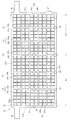
- FIG. 1 is a front view showing a configuration example of a grid plate used in a lead storage battery according to the present invention.
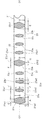
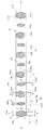
- 2 is an enlarged cross-sectional view showing the lattice plate of FIG. 1 along the line II-II of FIG. 3 is an enlarged cross-sectional view showing the lattice plate of FIG. 1 along the line III-III of FIG.
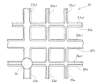
- FIG. 4 is an enlarged front view showing a part of the lattice plate of FIG.
- FIG. 5 is a cross-sectional view showing an example of the configuration of a mold used when the lattice plate of FIG. 1 is cast.
- FIG. 6 is a front view showing another example of a lattice plate used in the lead storage battery according to the present invention.
- FIG. 1 is a front view showing a configuration example of a grid plate used in a lead storage battery according to the present invention.
- FIG. 7 is a front view showing still another example of a grid plate used in the lead storage battery according to the present invention.
- FIG. 8 is a perspective view showing a configuration of an apparatus used when the lattice plate is filled with an active material.
- FIG. 9 is an exploded perspective view showing an example of the configuration of the lead storage battery.
- FIG. 9 is an exploded perspective view showing an example of the structure of a sealed lead-acid battery.
- reference numerals 1 and 2 denote a positive electrode plate and a negative electrode plate, respectively
- 3 denotes a separator
- the positive electrode plate 1 and the negative electrode plate 2 are alternately stacked via the separator 3 to constitute the electrode plate group 4.
- the positive plates 1, 1,..., The negative plates 2, 2,... And the separators 3, 3, the positive electrode plates 1 and the negative electrode plates 2 are alternately stacked via the separators 3 with their positions aligned.
- the strap 5 is a positive strap for connecting the ears provided on the plurality of positive plates 1, 1,... 6 is a negative strap for connecting the ears provided on the plurality of negative plates 2, 2,.
- the strap 5 and the negative strap 6 are respectively provided with a positive pole 5a and a negative pole 6a.
- the electrode plate group 4 is accommodated in the cell chamber 7a of the battery case 7 together with the electrolytic solution.
- the opening at the upper end of the battery case 7 is closed by a lid 8, and the positive pole 5 a and the negative pole 6 a are led out to the outside through holes respectively provided in the positive terminal bushing 9 and the negative terminal bushing 10 cast into the lid 8. Is done.
- the lid 8 is provided with an exhaust plug 11 that opens when the pressure in the battery case exceeds a specified value and opens the pressure in the battery case.
- the battery case 7 Since the storage battery shown in FIG. 9 is a single battery, the battery case 7 is provided with only one cell chamber. When the rated voltage of the battery exceeds 2V, a plurality of cell chambers are provided in the battery case 7, and electrode plate groups are inserted into each cell chamber, and predetermined electrode groups of electrode plates inserted into adjacent cell chambers By connecting the polar straps to each other via inter-cell connecting portions provided through the partition walls between the cell chambers, the batteries configured in the plurality of cell chambers are connected in series or in parallel. Thus, a lead storage battery having a predetermined rated voltage and rated capacity is configured.
- the positive electrode plate 1 and the negative electrode plate 2 each have a structure in which a positive electrode active material and a negative electrode active material are filled and held in a positive electrode lattice plate and a negative electrode lattice plate constituting the current collector, respectively.
- As the grid plate constituting the current collector those produced by casting and those produced by subjecting a lead or lead alloy plate to expansion processing are used. Use the manufactured grid plate.
- the lattice plate used in the lead-acid battery according to the present invention can be formed of an alloy material in which the main raw material is lead and an alloy material such as tin, calcium, antimony, sodium, etc. is added thereto. It is particularly preferable to use both tin and calcium as the alloy material added to the main raw material. Addition of calcium can reduce the rate of self-discharge. When calcium is added to the main raw material (lead), there arises a problem that bone corrosion easily occurs. However, bone corrosion can be suppressed by adding tin.
- the lattice plate includes a frame portion, a lattice provided inside the frame portion, and a current collecting ear portion provided in the frame portion.
- the frame portion is constituted by a pair of horizontal frame bones facing in the vertical direction and a pair of vertical frame bones facing in the horizontal direction, and a current collecting ear is provided on one of the horizontal frame bones.
- the lattice provided inside the frame portion is composed of a horizontal lattice bone extending parallel to the horizontal frame bone and a vertical lattice bone extending parallel to the vertical frame bone.
- FIG. 1 shows an example of a lattice plate 20 used in the lead storage battery according to this embodiment.
- the illustrated lattice plate 20 includes a frame portion 21 having a rectangular outline shape and a lattice 22 formed inside the frame portion 21.
- FIG. 1 shows the shape of the main surface on one end side in the thickness direction of the lattice plate 20, but the details of the shape of the main surface are not shown in the drawing.
- each bone has a hexagonal cross-sectional shape, the ridgeline of each bone actually appears on the main surface of the lattice plate as shown in the enlarged view of FIG.
- each part of the lattice plate will be described in detail.
- the frame portion 21 defines the outer shape of the lattice plate.
- the shape of the frame portion 21 is a shape adapted to the internal shape of the battery case (exterior case) of the lead storage battery used.
- the outline shape of the frame portion 21 is a square or a rectangle.
- the illustrated frame portion 21 has a pair of horizontal frame bones 21a and 21a extending in the horizontal direction and opposed in the vertical direction, and a pair of vertical frame bones 21b and 21b extending in the vertical direction and opposed in the horizontal direction.
- a current collecting ear portion 25 for connecting a strap (not shown) is integrally formed on one horizontal frame bone 21 a of the frame portion 21.
- the other lateral frame bone 21a of the frame portion 21 includes a holding ear portion 26 that protrudes on the opposite side of the current collecting ear portion 25, and a holding ear portion that is laterally separated from the holding ear portion 26.
- a foot part 27 protruding in the same direction is formed integrally with the frame part.
- the current collecting ear portion 25 and the lattice plate holding ear portion 26 are provided symmetrically, and in the process of manufacturing the electrode plate, the series of lattice plates 20 are arranged with their plate surfaces (main surfaces) in the horizontal direction. It is used to hold each lattice plate on a transporting tool when transported side by side while being suspended.
- the current collecting ears 25 and the lattice plate holding ears 26 are hooked on the carrier, whereby the lattice plates are held in a suspended state.
- the holding ear portion 26 is cut so as to form a foot portion having the same shape as the foot portion 27 after the filling of the active material into the lattice plate is completed.
- the foot formed by cutting the foot 27 and the holding ear 26 is formed between the lower end of the frame portion 21 and the bottom of the cell chamber when the electrode plate group is inserted into the cell chamber of the battery case. Used to form a gap. In some cases, the foot 27 is omitted. In this case, the entire holding ear 26 is cut after the filling of the lattice plate with the active material is completed.
- the current collecting ear 25 is used for connecting a strap for connecting the same polarity plates of the electrode plate group.
- the current collecting ear portion 25 is preferably formed in an appropriate shape and size in accordance with the shape of the battery case and its lid and the shape of the electrode plate.
- the number of the ears 25 is preferably one, and the thickness is preferably about the same as the thickness of the frame bone.
- the ear portion is preferably formed of the same material as the frame portion and the lattice portion.
- the portion of the grid plate 20 where the collecting ears 25 are provided is the upper portion of the grid plate, and the direction in which the vertical frame bone 21b extends (the longitudinal direction of the vertical frame bone) is the grid.
- the longitudinal direction of the plate 20 is assumed.
- the direction in which the lateral frame bone 21a extends is the lateral direction of the lattice plate, and the direction perpendicular to both the longitudinal direction and the lateral direction of the lattice plate 20 is the thickness direction of the lattice plate.
- the vertical direction, the horizontal direction, and the thickness direction of the electrode plate are directions along the vertical direction, the horizontal direction, and the thickness direction of the lattice plate 20, respectively.
- the direction along the thickness direction of the lattice plate is the thickness direction, and the direction perpendicular to both the longitudinal direction and the thickness direction is the width.
- the surface directed upward and the surface directed downward are defined as the front and back surfaces of the lattice plate, respectively.
- the cross-sectional shapes of the horizontal frame bone 21a and the vertical frame bone 21b have a large contact area with the active material and can be easily filled with the active material.
- the cross-sectional outlines of the horizontal frame bone 21a and the vertical frame bone 21b are hexagons elongated in the thickness direction of the frame portion.
- two opposite sides of the hexagonal six sides that define the cross section of each of the horizontal frame bone 21a and the vertical frame bone 21b are opposed to each other in the thickness direction of the frame portion 21.
- the horizontal frame bone 21a and the vertical frame are positioned so that the two vertices facing in the direction perpendicular to the opposing direction are positioned on the reference plane O1-O1 set to be perpendicular to the thickness direction of the frame portion.
- the direction of the hexagon that defines the cross section of the frame bone 21b is determined.
- the horizontal frame bone 21 a (FIG. 2) and the vertical frame bone 21 b (FIG. 3) have horizontal cross-sectional contours that are elongated in the thickness direction of the frame portion 21.
- the width dimension A of each of 21a and the vertical frame bone 21b is set smaller than the thickness dimension B.
- Flat end surfaces 21a1, 21a2 and 21b1, 21b2 are formed at both ends in the thickness direction of the horizontal frame bone 21a and the vertical frame bone 21b, respectively.
- the width dimensions C of the end faces 21a1, 21a2 and 21b1, 21b2 of the horizontal frame bone 21a and the vertical frame bone 21b are all set equal.
- the lattice 22 includes a plurality of horizontal lattice bones 23, 23,... And a plurality of vertical lattice bones 24, 24,.
- the material of the horizontal lattice bone and the vertical lattice bone may be the same as or different from the horizontal frame bone and the vertical frame bone described above. And in order to make it easy to integrally form the vertical lattice bones in one piece, the material constituting the horizontal lattice bone and the vertical lattice bone is the same as the material constituting the horizontal frame bone and the vertical frame bone. Is preferred.
- the plurality of horizontal lattice bones 23, 23,... are provided in parallel with the horizontal frame bone 21a, and are arranged side by side with a certain interval in the longitudinal direction of the vertical frame bone 21b.
- the plurality of longitudinal lattice bones 24, 24,... are provided so as to extend in parallel with the longitudinal frame bone 21b, and are arranged side by side with a certain interval in the longitudinal direction of the lateral frame bone 21a. ..
- the vertical lattice bones 24, 24,... Intersect at right angles to form a lattice 22.
- 26 horizontal lattice bones 23, 23,... Are provided, and 9 vertical lattice bones 24, 24,.
- the horizontal lattice bone 23 is composed of a plurality of fine bones 23a having a cross-sectional area that can withstand corrosion during the life of the lead-acid battery, and a plurality of thick bones 23b having a cross-sectional area larger than that of the thin bones 23a.
- the thick bone 23b and the thin bone 23a are arranged so that the bone adjacent to the bone 23b becomes the thin bone 23a.
- 21 fine bones 23a are provided and 5 thick bones 23b are provided.
- the vertical lattice bone 24 includes a plurality of fine bones 24a having a cross-sectional area that can withstand corrosion during the life of the lead-acid battery, and a plurality of thick bones 24b having a cross-sectional area larger than that of the thin bones 24a.
- the thick bone 24b and the thin bone 24a are arranged so that the bone adjacent to each thick bone 24b becomes the thin bone 24a.
- five fine bones 24a are provided, and four thick bones 24b are provided.
- the fine bones constituting the transverse lattice bone 23 are distinguished.
- 23a and the thick bone 23b are called a thin transverse bone and a thick transverse bone, respectively
- the thin bone 24a and the thick bone 24b constituting the longitudinal lattice bone 24 are called a thin longitudinal bone and a thick longitudinal bone, respectively.
- the narrow transverse bones 23a and the thick transverse bones 23b constituting the lattice 22 have a vertically long hexagonal cross-sectional shape extended in the thickness direction of the lattice plate. Is formed.
- two opposite sides of the hexagonal six sides that define the cross sections of the thin transverse bone 23a and the large transverse bone 23b are opposed to each other in the thickness direction of the frame portion 21.
- the thin transverse bone 23a is positioned so that two vertices opposed to a direction perpendicular to the side are positioned on a reference plane O1-O1 set to be perpendicular to the thickness direction of the frame portion.
- the cross-sectional shape of each of the large transverse bone 23b is defined.
- the reference plane O1-O1 is a plane along the dividing surface of the mold for casting the lattice plate.
- the end surface 23b2 is provided in a state where it is positioned on the same plane as the end surface 21a1 on one end side in the thickness direction of the frame portion 21 and the end surface 21a2 on the other end side.
- the width E of the thick transverse bone 23b is set smaller than the thickness D so that the contour shape of the cross section of the thick transverse bone 23b is a hexagon extending in the thickness direction.
- the width dimension G of the end face 23b2 on the other end side in the thickness direction of each thick transverse bone 21b is set smaller than the width dimension F of the end face on one end side in the thickness direction.
- the active material compression process performed thereafter is performed.
- the width dimension G of the end face 23b2 on the other end side in the thickness direction of each thick transverse bone 21b is set to be sufficiently small so that the end face 23b2 can be completely covered with the active material by the flow of the active material generated in FIG. Yes.
- the end surface 23a1 and the end surface 23a2 on the other end side are positioned on the inner side in the thickness direction of the frame portion than the end surface 21a1 on the one end side in the thickness direction of the lateral frame bone 21a and the end surface 21a2 on the other end side (frame portion). 21 (positioned inside 21 in the thickness direction).
- the width I of the narrow transverse bone 23a is set to be smaller than its thickness H so that the contour shape of the cross section of the thin transverse bone 23a is a hexagon extending in the thickness direction of the frame portion.
- the width dimension of the end surface 23a1 on the one end side in the thickness direction of the thin transverse bone 23a and the end surface 23a2 on the other end side can be set as appropriate, in this embodiment, the end surface 23a1 on one end side in the thickness direction of the thin transverse bone 23a and The end face 23a2 on the other end side has an equal width dimension J.
- the plurality of thick vertical bones 24 b constituting the vertical lattice bone 24 has a thickness K ( ⁇ B) smaller than the thickness B of the frame portion 21, and each thickness direction
- the end surface 24b1 on one end side is positioned on the same plane as the end surface on one end side in the thickness direction of the frame portion 21, and the end surface 24b2 on the other end side in the thickness direction is the end surface on the other end side in the thickness direction of the frame portion 21. It arrange
- the width L of the thick vertical bone 24b is set to be smaller than the thickness K so that the outline of the cross section of the thick vertical bone 24b is a hexagon extending long in the thickness direction of the frame portion.
- the width dimension of the end face 24b1 on one end side and the end face 24b2 on the other end side in the thickness direction of the thick vertical bone 24b can be set as appropriate, in the present embodiment, these end faces have the same width dimension M.
- the fine vertical bones 24a constituting the vertical lattice bone have a thickness N smaller than the thickness K ( ⁇ B) of the thick vertical bone 24b and a width P smaller than the width L of the thick vertical bone 24b.
- the end surface 24a1 on the one end side in the thickness direction and the end surface 24a2 on the other end side are respectively positioned on the inner side in the thickness direction of the frame portion than the end surface 21b1 on the one end side in the thickness direction of the vertical frame bone 21b and the end surface 21b2 on the other end side.
- the width P of the thin vertical bone 24a is set to be smaller than its thickness N so that the cross-sectional contour shape of the thin vertical bone 24a is a hexagon extending in the thickness direction of the frame portion.
- the width dimension of the end surface 24a1 on one end side in the thickness direction of the thin vertical bone 24a and the end surface 24a2 on the other end side can be set as appropriate, in this embodiment, the end surface 24a1 on one end side in the thickness direction of the thin vertical bone 24a and The end face 24a2 on the other end side has an equal width dimension Q.
- the thickness N of the thin vertical bone 24a is set equal to the thickness H of the thin horizontal bone
- the width P of the thin vertical bone 24a is set equal to the width I of the thin horizontal bone 23a.
- the width Q of the end face on one end side and the other end side in the thickness direction of the thin longitudinal bone 24a is set equal to the width J of the end face on one end side and the other end side in the thickness direction of the thin horizontal bone 23a.
- the thick bone and the thin bone are arranged so that the bone adjacent to each thick bone becomes a thin bone, but the thickness (width and thickness) of the thin bone constituting the horizontal lattice bone and the vertical lattice bone It is not always necessary to have one type, and a plurality of types of fine bones having different widths and thicknesses can be provided.
- the number of thin bones disposed between the frame bone and the thick bone and between the thick bone and the thick bone may be one or plural.
- the thickness (cross-sectional area) of the thick transverse bone 23b and the thick longitudinal bone 24b may be the same or different.
- the thickness of the thick transverse bone and the thickness of the thick longitudinal bone can be made different. For example, if the thickness of the thick transverse bone is made larger than the thickness of the longitudinal thick bone, the cavity for casting the horizontal lattice bone of the mold for casting the lattice plate is oriented in the vertical direction, and the lattice is formed by the gravity casting method.
- a large amount of molten lead can flow smoothly through a cavity (cavity extending in the vertical direction) that casts a large transverse bone 23b having a large cross-sectional area. It is possible to facilitate the casting by smoothing the flow of the molten metal.
- the relationship between the thickness of the thick transverse bone 23b and the thickness of the thin transverse bone 23a and the relationship between the thickness of the thick vertical bone 24b and the thickness of the thin vertical bone 24a are related to the ease of filling the active material, the life of the electrode plate, and the like. Set appropriately in consideration.
- the electrical resistance of the grid 22 increases as the distance from the current collecting ear 25 increases, and the voltage drop generated at the grid bone increases as the distance from the ear 25 increases. For this reason, the current flowing between the lattice bone and the active material at a location far from the current collecting ear 25 is restricted, and the charge / discharge reaction of the active material is less likely to be performed actively at a location away from the ear 25.
- the number of thin horizontal bones is equal to the number of thin horizontal bones provided per certain area in a region adjacent to one horizontal frame bone 21a provided with the current collecting ear portion 25.
- the ratio of the number of thin transverse bones per fixed area in the region near the other lateral frame bone away from the current collecting ear 25 to the number of thick transverse bones is more It is preferable to arrange the lattice bone so as to be small.
- the number of large transverse bones which is the number of thin transverse bones, on one lateral frame bone 21a side where the ear portion 25 is provided and on the other lateral frame bone 21a side located away from the ear portion, respectively.
- a first area A1 having a ratio to the first ratio and a second area A2 having a ratio of the number of thin transverse bones to the number of thick transverse bones a second ratio smaller than the first ratio are set.
- the ratio of the number of thin transverse bones to the number of thick transverse bones in the first region A1 and the second region A2 is not particularly limited, but in the present embodiment, the ratio is 1 in the first region A1.
- Four thin horizontal bones are lined up next to the large horizontal bone, and in the second area A2, the number of thick horizontal bones is set so that three thin horizontal bones are lined up next to one thick horizontal bone.
- a ratio with the number of fine horizontal bones is set. That is, the distance between the thick transverse bones 23b in the second area A2 is narrower than the distance between the thick transverse bones 23b in the first area A1.
- the paste-like active material can be easily filled while suppressing an increase in the electrical resistance (voltage drop) of the lattice as the distance from the ear portion increases. be able to.
- the thickness of the frame portion 21 is experimentally determined in consideration of the following points. If the thickness of the frame portion 21 is too thin, the thickness of the thick vertical bone set to be less than the thickness of the frame portion becomes too thin, the period until the lattice bone corrosion reaches the limit is shortened, and the life of the electrode plate is shortened. Tend to be shorter. Further, if the thickness of the frame portion 21 becomes too thin, the thickness of the horizontal and vertical thin bones becomes too thin, and the active material holding ability may be reduced.
- the thickness of the frame portion 21 is set to 5 mm or more, the thickness of the thick transverse bone 23b constituting the lattice bone is made equal to the thickness of the frame portion 21, the thickness of the thin transverse bone 23a and the thickness of the thick longitudinal bone 24b and the thin longitudinal bone 24a If it can be set to an appropriate value within a range of less than 5 mm, the requirement of extending the life of the electrode plate and the ease of filling the active material without reducing the active material holding capacity are improved. It is possible to meet both the demand for enhancement.
- the frame part 21 is a rectangle having the same size as the frame part of the grid plate used in the current industrial lead-acid battery.
- the long side dimension is 370 to 390 mm
- the short side dimension is 130 to 150 mm. It is preferable to form it in a rectangular shape.
- the dimension of the frame portion of the lattice plate is set to the above value, a relatively large electrode plate can be manufactured, and a battery having a large discharge capacity can be manufactured by using a large number of these electrode plates.
- the dimension of the above grid plate is about the same as the size of the grid plate used in industrial lead-acid batteries, it can be used without changing the battery case, lid, etc. of conventional industrial lead-acid batteries. A lead storage battery having a large discharge capacity and a long life can be obtained.
- the thick transverse bone 23b and the thick vertical bone 24b are provided with a function of maintaining the lattice shape in a predetermined shape over the lifetime of the battery. Therefore, in manufacturing the lattice plate of the present invention, the number of the large transverse bones 23b and the large longitudinal bones 24b is set to a number necessary for maintaining the shape of the lattice for a desired lifetime. In order not to reduce the amount of active material that can be filled in the lattice plate 20, the number of the thick transverse bones 23b and the thick longitudinal bones 24b is set so as not to be too large.
- the cross-sectional areas of the thick transverse bone 23b and the thick longitudinal bone 24b do not reduce the amount of active material that can be filled in the lattice plate, and maintain the shape of the lattice body over a desired lifetime. Set to the minimum necessary thickness (so as not to be too thick). The number and cross-sectional area of the thick transverse bone and the thick longitudinal bone are determined experimentally.
- the thin transverse bone 23a and the thin longitudinal bone 24a maintain a predetermined shape for a desired life period on the premise that they maintain their shapes with the help of the thick transverse bone 23b and the thick longitudinal bone 24b.
- the cross-sectional area of the size suitable for maintaining the function of holding the active material (the cross-sectional area smaller than the cross-sectional areas of the thick transverse bone and the thick longitudinal bone) is formed.
- the widths of the thin transverse bone 23a and the thin longitudinal bone 24a facilitate the flow of the paste-like active material between the thick transverse bone 23b and the thin transverse bone 23a and between the thick longitudinal bone 24b and the thin longitudinal bone 24a. Therefore, it is set to a size that can secure a space for the above.
- the widths of the narrow transverse bones 23a and the narrow longitudinal bones 24a are too wide, the meshes of the lattices are narrowed. Therefore, when the active material is filled, the flow of the active material is facilitated to facilitate the filling of the active material. This not only prevents the effect of the present invention from preventing a state where the active material is not covered with the active material, but also reduces the amount of active material that can be filled in the lattice plate.
- the cross-sectional area of the thin transverse bone and the thin longitudinal bone is too small, the corrosion of the thin transverse bone and the thin longitudinal bone reaches the deep part early and the mechanical strength is lowered. Even if borrowed, it becomes impossible to maintain the shape of the thin horizontal bone and the thin vertical bone, and the active material holding function is lowered.
- the cross-sectional areas of the thin transverse bone 23a and the thin longitudinal bone 24a are also experimentally determined.
- the gravity casting method is a method in which a raw material metal (alloy) of a grid plate is melted, and this molten metal (alloy) is cast by casting into a mold made of a material that can withstand the temperature of the molten metal.
- the gravity casting method there is no theoretical limit to the thickness of the grid that can be cast.
- it is easy to manufacture a lattice having both a large lattice bone and a fine lattice bone, and the obtained lattice plate has excellent current collecting characteristics and corrosion resistance.
- the first die 31 having the cavity 31a for forming one half in the thickness direction of the lattice body, and the lattice body
- a mold 33 including a second mold 32 having a cavity 32a for molding the other half in the thickness direction is used.
- the second die 32 is provided with an extrusion pin 34 used for releasing the cast lattice body.
- a cavity for molding each part of the lattice plate is formed inside the mold.
- 23b ' is a cavity for casting the horizontal thick bone 23b
- 24a' and 24b ' are cavities for casting the thin vertical bone 24a and the thick vertical bone 24b, respectively
- 21b' is a casting of the vertical frame bone 21b. It is a cavity to do.
- the first mold 31 and the second mold 32 are combined, and as shown in FIG. 5, the horizontal thick bone formed in the mold.
- molten lead alloy molten metal
- the first mold 31 is separated from the second mold 32, and the lattice plate remaining on the second mold 32 side is pushed by the push pins 34, The mold 32 is released from the second mold 32.
- the extrusion pin 34 shown at the top is used to extrude the solidified lead alloy in the gate 35 of the mold.
- the lattice plate 20 is provided with an extruding pin abutting seat 28 that abuts the extruding pin 4 when the cast lattice plate is extruded from the mold.
- the force applied from the extrusion pin is concentrated at one point to prevent the lattice plate from being deformed. It is preferable to provide a cross-sectional area larger than the cross-sectional area of each crossing portion at the crossing portion of the bone or the vertical lattice bone and the crossing portion of the horizontal lattice bone and the vertical lattice bone.
- the small frame provided at the intersection of one vertical frame bone 21b and the five large horizontal bones 23b and one vertical frame bone 21b near one end and the other end in the vertical direction.
- the horizontal bones 23a, 23a At the intersection of the horizontal bones 23a, 23a, at the intersection of one thin vertical bone 24a and five thick horizontal bones 23b arranged at the center in the horizontal direction of the lattice plate, and at the horizontal center of the lattice plate Pushing pin abutting seats 28 are respectively formed at the intersections between the arranged thin vertical bones 24a and the two horizontal frame bones 21a and 21a.
- Each push pin abutment seat 28 has an intersection between the vertical frame bone 21b and the thick horizontal bone 23b or the thin horizontal bone 23a, an intersection between the horizontal frame bone 21a and the thin vertical bone 24a, and the thick horizontal bone 23b. It is formed so as to have a cross-sectional area larger than each cross-sectional area of the intersection with the vertical bone 24a.
- the arrangement of the push pin contact seats 28 is not limited to the example shown in FIG.
- the push pin contact seats 28 may be arranged.
- an active material filling step and an active material compression step are performed.
- a paste filling machine 41 that performs an active material filling process and an example of a compressor 42 that performs an active material compression process are shown.
- the illustrated paste filling machine 41 is in contact with the conveying belt 41b that is guided by a roller 41a and travels in one direction, and the lattice plate 20 supplied on the conveying belt 41b from above, and the lattice plate 20 is moved toward the conveying belt 41b.
- It consists of a feed roller 41c that rotates while being pressed, and a paste supply device 41d that supplies a paste-like active material to the grid plate 20 on the conveyor belt 41b while applying pressure.
- the conveyor belt 41b and the feed roller 41c are driven by a motor (not shown).
- the compressor 42 includes a plurality of feed rollers 42a arranged with their axes oriented in a direction perpendicular to the transport direction, and a pressure roller 42b urged toward the feed roller 42a by an air cylinder, a spring, or the like.
- the active material filled in the lattice plate is latticed while being fed in one direction with the electrode plate supplied from the paste filling machine 41 side being sandwiched between the feed roller 42a and the pressure roller 42b. Compress and harden in the thickness direction of the plate.
- the lattice plate 20 cast in the casting process is transported by a transport device (not shown) and supplied to the end of the transport belt 41b.
- the lattice plate 20 has the horizontal direction in the conveyance direction, the vertical direction in the direction perpendicular to the conveyance direction, and one main surface (front surface) in the thickness direction facing upward. Supplied on top.
- the lattice plate 20 supplied onto the transport belt 41b is fed into the paste supply device 41d while being sandwiched between the feed roller 41c and the transport belt 41b.
- the paste supply device 41d supplies a paste-like active material to the surface of the lattice plate 20 at a predetermined pressure.
- the active material supplied to the surface of the grid plate 20 covers the surface of the grid plate 20 and flows to the back side of the grid plate through the eyes of the grid 22, and the inside of the grid 22 and the back side of the grid plate Filled.
- the active material to be filled in the lattice plate is not particularly limited, but is preferably prepared by kneading lead powder containing lead monoxide, water, sulfuric acid and the like.
- additives such as cut fiber, carbon powder, lignin, barium sulfate, and red lead may be added to the active material.
- the amount of the active material to be filled is not a problem as long as the bones (thin bones and thick bones) formed inside the frame bone are completely hidden, but it is desirable to fill up the thickness of the frame bone or more.
- the lattice plate (electrode plate) filled with the active material is transported by the transport belt 41 b and supplied to the compressor 42.
- the electrode plate supplied to the compressor 42 is fed while being pressed between the feed roller 42a and the pressure roller 42b. In this process, the active material is compressed and compressed in the thickness direction of the lattice plate.
- the electrode plate according to the present invention is manufactured by filling the above-mentioned paste-like active material into a lattice plate with a paste filling machine, and aging and drying.
- the time and temperature for aging and drying are not particularly limited, but it is preferable to adjust to a suitable value depending on the thickness of the lattice plate and the physical properties of the active material.
- the configuration of the lead storage battery according to the present invention is not particularly limited, except that at least the grid plate according to the present invention is used for the positive electrode plate.
- the lead-acid battery is manufactured from members such as a positive electrode plate, a negative electrode plate, dilute sulfuric acid as an electrolytic solution, a separator (such as a glass fiber retainer), a battery case, and a lid.
- a separator such as a glass fiber retainer
- the positive electrode plates 1 and the negative electrode plates 2 are alternately stacked one by one, so The parts are connected by the straps 5 and 6 to constitute the electrode plate group 4.
- the electrode plate group 4 is put in a battery case 7 and covered, and after dilute sulfuric acid is poured into the battery case, chemical conversion is performed to complete a lead storage battery.
- the end surface on one end side in the thickness direction of the thick transverse bone 23b and the end surface on one end side in the thickness direction of the thick vertical bone 24b are one end side in the thickness direction of the frame portion 21. Therefore, when the grid plate 20 is fed into the paste filling machine by the feed roller 41c, a sufficient contact area between the feed roller 41c and the grid plate 20 can be secured to feed the grid plate 20 into the paste filling machine. The frictional resistance between the roller 41c and the lattice plate 20 can be increased.
- the end surface on the other end side in the thickness direction of the thick transverse bone 23b is disposed on the same plane as the end surface on the other end side in the thickness direction of the frame portion 21.
- the contact area between the belt 20 and the conveyor belt can be increased to increase the frictional resistance between them. Therefore, when the grid plate is sandwiched between the transport belt and the feed roller and supplied to the paste filling machine, the frictional resistance between the grid plate and the feed roller and between the grid plate and the transport belt is sufficiently increased.
- the grid plate can be reliably fed into the paste filling machine 41 in a state in which the grid plate is kept in a normal posture with the lateral direction thereof directed in the transport direction, and the filling operation of the active material can be performed smoothly. .
- the end surfaces in the thickness direction of both the thick transverse bone 23b and the thick longitudinal bone 24b and the thickness direction of the frame portion 21 are used.
- the frame bones 21a, 21b, the thick horizontal bones 23b, and the thick vertical bones 24b are arranged side by side in the vertical and horizontal directions, and the surface of the lattice plate 20 is in a state of being partitioned in the vertical and horizontal directions by these partition frames.
- the grids are passed through the limited areas in each partition frame without dispersing the filling pressure of the active material applied to the surface of the grid plate. Since it can transmit to the back surface side of a board uniformly and reliably, the flow of the active material from the surface side of a lattice board to a back surface side can be performed uniformly and smoothly.
- the end surface 24b2 in the thickness direction of the thick vertical bone 24b and the end surface 24a2 of the thin vertical bone 24a are arranged on the inner side in the thickness direction of the frame portion than the end surfaces 21a2 and 21b2 of the frame portion.
- the active material on the back side of the lattice plate 20 It is possible to facilitate the flow of the active material and to satisfactorily fill the active material.
- the end faces in the thickness direction of both the thick transverse bone 23b and the thick longitudinal bone 24b are on the same plane as the end faces in the thickness direction of the frame portion 21 on the surface side.
- it is arranged it is easy to apply the active material on the surface side of the lattice plate so as to hide the thick transverse bone and the thick longitudinal bone when the active material is filled. Therefore, even if the end face in the thickness direction of the thick transverse bone and the thick longitudinal bone and the end face in the thickness direction of the frame portion are arranged on the same plane on the surface side of the lattice plate, the thick transverse bone and the thick longitudinal bone are It is easy to fill the active material so that it is not exposed.
- the end surface 23 b 2 on the other end side in the thickness direction of the thick transverse bone 23 b is arranged on the same plane as the plane on which the end surface on the other end side in the thickness direction of the frame portion 21 is arranged. Therefore, the end surface 23b2 in the thickness direction of the thick transverse bone 23b may be exposed without being covered with the active material. Although it is difficult to completely cover the end face of the thick horizontal bone exposed on the back side of the grid plate only by the flow of the active material from the front side to the back side of the grid plate.
- the width dimension G of the end surface in the thickness direction of each thick transverse bone 23b on the back side of the lattice plate is larger than the width dimension F of the end surface in the thickness direction of each thick transverse bone on the surface side of the lattice plate. Since it is set small, even if the end surface 23b2 in the thickness direction of the thick transverse bone 23b is exposed on the back surface side of the electrode plate at the end of the active material filling step, the area of the exposed portion can be made sufficiently small.
- the flow of the active material that occurs in the active material compression process performed thereafter causes the The exposed portion of the end surface 23b2 on the other end side in the thickness direction, and an electrode plate having no exposed portion of the lattice bone on both the front and back surfaces of the lattice plate can be easily obtained.
- the vertical lattice bones are provided so that the thick vertical bones and the thin vertical bones are alternately arranged along the longitudinal direction of the lateral frame bones 21a and 21b. As shown, it is not limited to the case where the vertical lattice bone is configured.
- the vertical lattice bone may be configured so that the two fine vertical bones 24a are arranged next to the thick vertical bone 24b.
- the main surface of the lattice plate is positioned on the side of the one side frame bone provided with the ear portion on the side of the one side frame bone and on the side of the other side frame bone away from the ear portion.
- a second region A2 is formed, the main surface of the lattice plate is divided into two in the longitudinal direction (up and down), and in the first region, four thin transverse bones are arranged on the side of each thick transverse bone, In the second region, three thin horizontal bones are arranged side by side on each thick horizontal bone, but the present invention is not limited to the above embodiment.
- a narrow horizontal width provided per certain area in a region adjacent to one lateral frame bone provided with the ear portion.
- the number of thin transverse bones provided per fixed area in the area near the other lateral frame bone located far from the ear part The ratio of the number of fine transverse bones to the number of thick transverse bones in each region of the main surface of the lattice plate is not limited to the above example.
- one or more regions are further provided between the first region A1 and the second region A2, and the main surface of the lattice plate is divided into three or more regions in the vertical direction, while the ears are provided.
- the ratio of the number of fine transverse bones provided per fixed area to the number of thick transverse bones increases from the region provided on the lateral frame bone side to the region provided on the other lateral frame bone side.
- the number of thin transverse bones and the number of thick transverse bones in each region may be set so that the number of the transverse bones decreases in a stepwise manner (so that the space between the thick and horizontal lattices gradually decreases).
- the lattice plate A has the structure previously proposed by the present inventor (shown in Patent Document 3).
- the arrangement pattern of the horizontal lattice bones 23 and the vertical lattice bones 24 inside the frame portion 21 is the same as the example shown in FIG. 1, but in the lattice plate A, the thick transverse bones 23b and the thick vertical bones 24b are arranged.
- the thickness is set smaller than the thickness of the frame portion 21, and the end surface 23 b 1 on one end side in the thickness direction of the thick transverse bone 23 b and the end surface 23 b 2 on the other end side are end surfaces 21 a 1, 21 b 1 on one end side in the thickness direction of the frame portion 21.
- the thin transverse bones 23a and the thin vertical bones 24a are located at positions where the end surfaces on one end side in the thickness direction are biased toward the plane where the end surfaces on the one end side in the thickness direction of the thick horizontal bones 23b and thick vertical bones 24b are arranged. It is provided in a positioned state.
- the vertical dimension of the frame portion 21 is 385 mm
- the horizontal dimension is 140 mm
- the thickness is 5.8 mm
- the width is 4.4 mm
- the thick horizontal bone 23b and the thin horizontal bone 23a are provided inside the frame portion 21.
- the provided horizontal lattice bone 23 and the vertical lattice bone 24 including the thick vertical bone 24b and the thin vertical bone 24a were formed.
- the cross-sectional shape of the thick transverse bone 23b and the thick longitudinal bone 24b was a hexagon whose thickness was larger than the width, the thickness was 5.4 mm, and the width was 4.3 mm.
- the cross-sectional shapes of the thin transverse bone 24a and the thin longitudinal bone 24a were also hexagons having a thickness larger than the width, and the thickness was 3.6 mm and the width was 2.8 mm.
- the end surfaces 23a1 and 24a1 on one end side in the thickness direction of the thin transverse bone 23a and the thin longitudinal bone 24a arranged in the upward direction when filled with the active material are replaced by the thick transverse bone 23b and the thick longitudinal bone 24b. It was located on the same plane as the end faces 23b1 and 24b1 on one end side in the thickness direction.
- ⁇ Lattice plate B Example>
- the arrangement pattern of the horizontal lattice bones 23 and the vertical lattice bones 24 inside the frame portion 21 is the same as the example shown in FIG.
- the thickness of the thick transverse bone 23b is set equal to the thickness of the frame portion 21, and the end face 23b1 on one end side in the thickness direction of the thick transverse bone 23b and the end face on the other end side.
- 23b2 is disposed on the same plane as the end faces 21a1, 21b1 on one end side in the thickness direction of the frame portion 21 and the end faces 21a2, 21b2 on the other end side. As shown in FIG.
- the thickness of the thick vertical bone 24b is set smaller than the thickness of the frame portion 21, and the end surface 24b1 on one end side in the thickness direction is an end surface 21a1 on one end side in the thickness direction of the frame portion 21.
- the end surface 24b2 on the other end side in the thickness direction of the thick vertical bone 24b is disposed on the same plane as 21b1, and is located on the inner side in the thickness direction of the frame portion than the end surfaces 21a2 and 21b2 on the other end side in the thickness direction of the frame portion 21. Is arranged.
- the width and thickness of the thin transverse bone 23a are set smaller than the width and thickness of the thick transverse bone 23b, respectively, and the width and thickness of the thin longitudinal bone 24a are respectively smaller than the width and thickness of the thick longitudinal bone 24b.
- the thin transverse bones 23a and the thin vertical bones 24a have end faces 23a1 and 24a1 on one end side in the thickness direction positioned inside the end face on one end side in the thickness direction of the frame part 21 in the thickness direction of the frame part, and The end surfaces 23a2 and 24a2 on the other end side in the thickness direction are provided in a state where the end surfaces on the other end side in the thickness direction of the frame portion 21 are positioned on the inner side in the thickness direction of the frame portion.
- the vertical dimension of the frame portion 21 is 385 mm
- the horizontal dimension is 140 mm
- the thickness B is 5.8 mm
- the width A is 4.4 mm
- the thick horizontal bone 23b and the thin horizontal bone 23a are placed inside the frame portion.
- the cross-sectional shape of the thick transverse bone 23b was a hexagon whose thickness D was larger than the width E, the thickness D was 5.8 mm, and the width E was 4.3 mm.
- the width F of the end surface 23b1 on one end side in the thickness direction of the thick transverse bone 23b and the width G of the end surface 23b2 on the other end side were 1.7 mm and 1.0 mm, respectively.
- the cross-sectional shape of the thick vertical bone 24b is also a hexagon whose thickness K is larger than the width L, the thickness K is 5.6 mm, and the width L is 4.3 mm.
- the cross-sectional shapes of the thin transverse bone 24a and the thin longitudinal bone 24a are also hexagons having thicknesses H and N larger than the widths I and P, the thicknesses H and N being 3.6 mm, and the widths I and P being 2.8 mm. It was.
- the end surfaces 23a1 and 24a1 on one end side in the thickness direction of the thin transverse bone 23a and the thin longitudinal bone 24a are closer to the inner side in the thickness direction of the frame portion than the end surface on one end side in the thickness direction of the frame portion 21.
- the end surfaces 23a2 and 24a2 on the other end side in the thickness direction of the thin transverse bone 23a and the thin longitudinal bone 24a are positioned on the same plane at the same position, and the frame portion is located on the other end side in the thickness direction of the frame portion 21. It was located on the same plane at a position close to the inside in the thickness direction.
- the paste-like active material for positive electrode used in the active material filling experiment was prepared by adding 0.1% by mass of polyester fiber to the mass of lead powder containing lead monoxide as a main component and mixing 12 masses of water. %, 16% by mass of diluted sulfuric acid was added and kneaded again.
- the method for producing the positive electrode active material is the same as the conventional method.
- both the lattice plates A and B are All the lattice bones were neatly embedded in the active material, and the active material was well packed on the back side of the lattice plate.
- the reason why the end face 23b2 of the thick transverse bone is not exposed on the back side of the lattice plate is that By forming a partition frame with a large transverse bone and a large longitudinal bone on the front side, the flow of the active material from the front side to the back side of the lattice plate was made smooth, and the other end in the thickness direction of the thick transverse bone This is probably because the width G of the end face 23b2 on the side is made smaller than the end face 23b1 on the one end side in the thickness direction of the thick transverse bone.
- the rate of occurrence of the same trouble is reduced to 0.7%, and the trouble due to the failure of feeding the lattice plate to the paste filling machine is Good results were obtained, a 48% reduction compared to the case of using a plate.
- the present invention it is possible not only to satisfactorily fill the lattice plate with the active material as in the case of using the previously proposed lattice plate, but also to use the lattice plate as a paste filling machine. It has become clear that the number of times the line is stopped due to troubles during supply can be greatly reduced compared to the case of using the proposed grid plate.
- the cross-sectional area of the thick transverse bone can be made larger than the cross-sectional area of the large transverse bone of the lattice plate used in the proposed lead-acid battery, and
- the cross-sectional area of the horizontal bone and the thin vertical bone can be made equal to the cross-sectional area of the thick vertical bone and the cross-sectional area of the thin horizontal bone and the thin vertical bone of the proposed lattice plate, respectively.
- it is clear that it has a life characteristic equal to or better than that of the previously proposed lead acid battery.
- the lattice plate can be smoothly fed into the paste filling machine, the probability that the line stops due to the failure to correctly feed the lattice plate into the paste filling machine is reduced.
- the productivity of the electrode plate can be improved.
- the lattice plate can have a structure that can withstand long-term corrosion and a structure that facilitates filling of the active material, the life of the electrode plate, in particular, the positive electrode plate can be extended and the life can be increased.
- a control valve type lead acid battery can be obtained.
- Lattice plate 21 Frame portion 21a Horizontal frame bone 21b Vertical frame bone 22 Grid 23 Horizontal lattice bone 23a Fine horizontal bone 23a1 End face on one end side in the thickness direction of the fine horizontal bone 23a2 End face 23b on the other end side in the thickness direction of the fine horizontal bone Thick transverse bone 23b1 End face on one end side in the thickness direction of the thick transverse bone 23b2 End face on the other end side in the thickness direction of the thick transverse bone 24 Vertical lattice bone 24a Fine longitudinal bone 24a1 End face on one end side in the thickness direction of the thin longitudinal bone 24a2 Fine End face on the other end side in the thickness direction of the longitudinal bone 24b Thick longitudinal bone 24b1 End face on the one end side in the thickness direction of the thick longitudinal bone 24b2 End face on the other end side in the thickness direction of the thick longitudinal bone 25 Current collecting ear portion 26 Lattice plate holding Ear part 27 Foot part
Landscapes
- Chemical & Material Sciences (AREA)
- Chemical Kinetics & Catalysis (AREA)
- Electrochemistry (AREA)
- General Chemical & Material Sciences (AREA)
- Engineering & Computer Science (AREA)
- Manufacturing & Machinery (AREA)
- Cell Electrode Carriers And Collectors (AREA)
- Battery Electrode And Active Subsutance (AREA)
Abstract
Description
a.縦格子骨及び横格子骨の少なくとも一方が太骨と細骨とにより構成されて、各太骨に隣接する格子骨が細骨となるように太骨と細骨とが配列される。
b.太骨の厚みが枠部の厚みよりも小さく設定されて、太骨の厚み方向の一端側の端面及び他端側の端面が枠部の厚み方向の一端側の端面及び他端側の端面よりも厚み方向の内側に配置される。
c.細骨の幅及び厚みはそれぞれ太骨の幅及び厚みよりも小さく設定され、各細骨は、その厚み方向の一端側の端面を太骨の厚み方向の一端側の端面が配置された平面寄りに偏った位置させた状態で設けられる。
(1.1)横方向に伸び縦方向に相対する一対の横枠骨と縦方向に伸び横方向に相対する一対の縦枠骨とを有し、横方向及び縦方向の双方に対して直角な厚み方向に一定の厚み寸法を有する枠部と、横枠骨及び縦枠骨とそれぞれ平行に伸びるように設けられて枠部の内側に格子を形成する複数の横格子骨及び複数の縦格子骨と、枠部の一方の横枠骨に一体に形成された集電用耳部とを備えている。
(1.2)縦格子骨及び横格子骨はそれぞれ、複数の細縦骨及び細横骨と、細縦骨及び細横骨よりも断面積が大きい複数の太縦骨及び太横骨とを有して、各太縦骨の側方に少なくとも一つの細縦骨が並び、各太横骨の側方に複数の細横骨が並ぶように、太縦骨及び細縦骨と太横骨及び細横骨とが配列される。
(1.3)複数の太縦骨は、枠部の厚みよりも小さい厚みを有して、それぞれの厚み方向の一端側の端面を前記枠部の厚み方向の一端側の端面と同一平面上に位置させ、かつそれぞれの厚み方向の他端側の端面を前記枠部の厚み方向の他端側の端面よりも前記枠部の厚み方向の内側に位置させた状態で配置される。
(1.4)複数の細縦骨は、太縦骨の厚みよりも小さい厚みを有して、それぞれの厚み方向の一端側の端面及び他端側の端面をそれぞれ太縦骨の厚み方向の一端側の端面及び他端側の端面よりも枠部の厚み方向の内側に位置させた状態で配置される。
(1.5)複数の太横骨は、枠部の厚みに等しい厚みを有して、それぞれの厚み方向の一端側の端面及び他端側の端面をそれぞれ枠部の厚み方向の一端側の端面及び他端側の端面と同一の平面上に位置させた状態で配置される。
(1.6)各太横骨は、その厚み方向及び長手方向の双方に対して直角な方向を幅方向としたときに、その厚み方向の他端側の端面の幅寸法が、その厚み方向の一端側の端面の幅寸法よりも小さく設定される。
(1.7)複数の細横骨は、太横骨の厚みよりも小さい厚みを有して、それぞれの厚み方向の一端側の端面及び他端側の端面をそれぞれ太横骨の厚み方向の一端側の端面及び他端側の端面よりも枠部の厚み方向の内側に位置させた状態で配置される。
図9は、密閉型鉛蓄電池の構造の一例を示す分解斜視図である。同図において1及び2はそれぞれ正極板及び負極板、3はセパレータで、正極板1及び負極板2がセパレータ3を介して交互に積層されることにより極板群4が構成される。
枠部21は、格子板の外形形状を画定するものである。枠部21の形状は、使用される鉛蓄電池の電槽(外装ケース)の内部形状に適合させた形状とされる。本実施形態では、立方体または直方体状の電槽を用いるため、枠部21の輪郭形状を正方形又は長方形とする。
格子22は、複数本の横格子骨23,23,…と、複数本の縦格子骨24,24,…とからなっている。横格子骨及び縦格子骨の材質は、先に述べた横枠骨及び縦枠骨と同じものであっても、異なるものであっても良いが、横枠骨、縦枠骨、横格子骨及び縦格子骨を、一括して一体成形することを容易にするために、横格子骨及び縦格子骨を構成する材料は、横枠骨及び縦枠骨を構成する材料と同じものであることが好ましい。
太横骨23b及び太縦骨24bの太さ(断面積)は、同一であってもよく、異なっていてもよい。格子板の鋳造性を考慮して、太横骨の太さと太縦骨の太さとを異ならせることができる。例えば、太横骨の太さを縦太骨の太さよりも太くしておくと、格子板を鋳造する鋳型の横格子骨を鋳造するキャビティを鉛直方向に向けた状態で、重力鋳造方式により格子板を鋳造する際に、断面積が大きい太横骨23bを鋳造するキャビティ(鉛直方向に伸びるキャビティ)内を通して、大量の溶融鉛を円滑に流すことができるため、縦格子骨を鋳造するキャビティ内への溶湯の流れを円滑にして、鋳造を容易にすることができる。
本実施形態では、図1に示されているように、横枠骨21aの長手方向に太縦骨24bと細縦骨24aとが交互に並ぶように、縦格子骨24を構成する細縦骨24a及び太縦骨24bが設けられている。
枠部21の厚みは以下の点を考慮して実験的に決定する。枠部21の厚みが薄すぎると、枠部の厚み未満に設定される太縦骨の厚みが薄くなり過ぎて、格子骨の腐食が限界に達するまでの期間が短くなり、極板の寿命が短くなる傾向がある。また枠部21の厚みが薄くなり過ぎると、横細骨及び縦細骨の厚みが薄くなり過ぎるため、活物質の保持能力が低下するおそれがある。枠部21の厚みを5mm以上として、格子骨を構成する太横骨23bの厚みを枠部21の厚みに等しくし、細横骨23aの厚みと太縦骨24b及び細縦骨24aの厚みとを5mm未満の範囲で適当な値に設定することができるようにしておくと、極板の寿命を長くするという要求と、活物質の保持能力を低下させることなく活物質の充填の容易性を高めるという要求との双方に応えることができる。
本発明においては、太横骨23b及び太縦骨24bの部分に、電池の寿命期間に亘って格子の形状を所定の形状に維持する機能を持たせる。従って本発明の格子板を製作するに当たって、太横骨23b及び太縦骨24bの本数は、所望の寿命期間の間格子の形状を維持するために必要な本数に設定される。格子板20に充填し得る活物質量を減少させることがないようにするために、太横骨23b及び太縦骨24bの本数は多すぎないように設定する。同様に、太横骨23b及び太縦骨24bの断面積は、格子板に充填し得る活物質量を減少させることがなく、かつ所望の寿命期間に亘って格子体の形を保持するために必要最小限の太さに(太すぎないように)設定する。太横骨及び太縦骨の本数及び断面積は、実験的に決定する。
一方細横骨23a及び細縦骨24aは、太横骨23b及び太縦骨24bの力を借りて自らの形状を維持することを前提にして、所望の寿命期間の間所定の形状を保持し、活物質を保持する機能を維持するのに適した大きさの断面積(太横骨及び太縦骨の断面積よりは小さい断面積)を持つように形成する。また細横骨23a及び細縦骨24aの幅は、太横骨23bと細横骨23aとの間及び太縦骨24bと細縦骨24aとの間にペースト状活物質の流動を容易にするためのスペースを確保することができる大きさに設定される。
格子板の製造方法としては、重力鋳造方式(GDC:Gravity Die Casting)、連続鋳造方式、エキスパンド方式、打ち抜き方式等があるが、本発明に係わる格子板の製造には重力鋳造方式を用いることが好ましい。重力鋳造方式は、格子板の原材料金属(合金)を溶融し、この溶融金属(合金)を、該溶融金属の温度に耐え得る材料からなる金型内に重力により流し込み、鋳造する方法である。重力鋳造方式では、鋳造可能な格子の太さに理論上限界がない。また重力鋳造方式によれば、太格子骨と細格子骨とを合わせ持つ格子の製造が容易であり、得られた格子板の集電特性及び耐食性が優れている。
格子板20を用いて鉛蓄電池用極板を製造する際には、活物質充填工程と活物質圧縮行程とを行う。図8を参照すると、活物質充填工程を行うペースト充填機41の一例と、活物質圧縮行程を行う圧縮機42の一例とが示されている。図示のペースト充填機41は、ローラ41aによりガイドされて一方向に走行する搬送ベルト41bと、搬送ベルト41b上に供給された格子板20に上方から接して、格子板20を搬送ベルト41b側に押しつけながら回転する送りローラ41cと、搬送ベルト41b上の格子板20にペースト状の活物質を加圧しながら供給するペースト供給装置41dとからなっている。搬送ベルト41b及び送りローラ41cは、図示しないモータにより駆動される。
本発明に係わる鉛蓄電池の構成は、少なくとも正極板に本発明に係わる格子板を用いる点を除き、特に限定されるものではない。前述のように、鉛蓄電池は、正極板、負極板、電解液としての希硫酸、セパレータ(ガラス繊維製のリテーナ等)、電槽、蓋等の部材から作製される。例えば、図9に示されるように、正極板1と負極板2との間にセパレータを介在させながら、正極板1と負極板2とを1枚ずつ交互に積層して、同極板の耳部同士をストラップ5及び6で連結させ、極板群4を構成する。この極板群4を電槽7の中に入れて蓋をし、電槽内に希硫酸を注液した後に化成を行って鉛蓄電池を完成する。
図1に示した例では、太縦骨と細縦骨とが横枠骨21a,21bの長手方向に沿って交互に並ぶように縦格子骨を設けているが、本発明は、図1に示したように縦格子骨を構成する場合に限定されるものではない。例えば、太縦骨24bの隣に2本の細縦骨24aが並ぶように縦格子骨を構成しても良い。
鉛に、スズ:1.0~1.8質量%、カルシウム:0.05~0.1質量%を添加して作製した鉛合金を溶融し、異なる2種類の金型を用いて、重力鋳造方式により正極用の格子板A及び格子板Bを作製した。これらの格子板のうち、格子板Aは比較例であり、格子板Bは本発明の実施例である。
格子板Aは、本発明者が先に提案した構造を有するもの(特許文献3に示されたもの)である。格子板Aにおいて、枠部21の内側の横格子骨23及び縦格子骨24の配列パターンは図1に示した例と同様であるが、格子板Aでは太横骨23b及び太縦骨24bの厚みが枠部21の厚みよりも小さく設定されて、太横骨23bの厚み方向の一端側の端面23b1及び他端側の端面23b2が枠部21の厚み方向の一端側の端面21a1,21b1及び他端側の端面21a2,21b2よりも厚み方向の内側に配置されている。また太縦骨24bの厚み方向の一端側の端面24b1及び他端側の端面24b2が枠部21の厚み方向の一端側の端面21a1,21b1及び他端側の端面21a2,21b2よりも厚み方向の内側に配置されている。細横骨23aの幅及び厚みはそれぞれ太横骨23bの幅及び厚みよりも小さく設定され、細縦骨24aの幅及び厚みはそれぞれ太縦骨24bの幅及び厚みよりも小さく設定されている。各細横骨23a及び細縦骨24aは、それぞれの厚み方向の一端側の端面を太横骨23b及び太縦骨24bの厚み方向の一端側の端面が配置された平面寄りに偏った位置に位置させた状態で設けられている。
格子板Bにおいて、枠部21の内側の横格子骨23及び縦格子骨24の配列パターンは図1に示した例と同様である。格子板Bにおいては、図2に示すように、太横骨23bの厚みが枠部21の厚みに等しく設定されて、太横骨23bの厚み方向の一端側の端面23b1及び他端側の端面23b2が枠部21の厚み方向の一端側の端面21a1,21b1及び他端側の端面21a2,21b2と同一の平面上に配置されている。また図3に示すように、太縦骨24bの厚みは枠部21の厚みよりも小さく設定されて、その厚み方向の一端側の端面24b1は枠部21の厚み方向の一端側の端面21a1,21b1と同一平面上に配置され、太縦骨24bの厚み方向の他端側の端面24b2は、枠部21の厚み方向の他端側の端面21a2,21b2よりも枠部の厚み方向の内側に配置されている。
格子板A及びBに対して、ペースト充填機によりペースト状の活物質を充填する活物質充填実験を実施し、その後、熟成・乾燥をして未化成の正極板を作製した。
格子板A及びBにペースト状活物質を充填、圧縮した後、活物質充填時に下方に向いていた格子板の裏側への活物質の充填状態を視認した結果、格子板A及びBの双方とも、すべての格子骨が活物質中に綺麗に埋まっており、格子板の裏側への活物質の充填状態は良好であった。本発明においては、太横骨23bの厚みDを枠部21の厚みBに等しくしているにも拘わらず、格子板の裏面側で太横骨の端面23b2が露出しない理由は、格子板の表面側に太横骨と太縦骨とにより仕切り枠を形成したことにより、格子板の表面側から裏面側への活物質の流動を円滑にしたことと、太横骨の厚み方向の他端側の端面23b2の幅Gを太横骨の厚み方向の一端側の端面23b1に比べて小さくしたこととによるものと思われる。
格子板Aにおいては、格子板を、その横方向を搬送方向に向けた状態で搬送ベルトの上に載せて、搬送ベルト上の格子板20に送りローラを接触させることによりペースト充填機に送り込む際に、格子板の姿勢が正規の姿勢からずれてラインが停止するトラブルが全数の1.2%の割合で生じた。これは、正極板100個当たり1.2個の不良品が生じることを意味し,生産性を向上させる上で無視できない値である。これに対し、本発明の実施例である格子板Bにおいては、同様のトラブルが生じる割合が0.7%まで減少し、ペースト充填機への格子板の送り込みの不具合によるトラブルが既提案の格子板を用いる場合に比べて48%も減少するという好結果が得られた。
21 枠部
21a 横枠骨
21b 縦枠骨
22 格子
23 横格子骨
23a 細横骨
23a1 細横骨の厚み方向の一端側の端面
23a2 細横骨の厚み方向の他端側の端面
23b 太横骨
23b1 太横骨の厚み方向の一端側の端面
23b2 太横骨の厚み方向の他端側の端面
24 縦格子骨
24a 細縦骨
24a1 細縦骨の厚み方向の一端側の端面
24a2 細縦骨の厚み方向の他端側の端面
24b 太縦骨
24b1 太縦骨の厚み方向の一端側の端面
24b2 太縦骨の厚み方向の他端側の端面
25 集電用耳部
26 格子板保持用耳部
27 足部
Claims (2)
- 正極用の格子板に正極活物質を充填してなる正極板と、負極用の格子板に負極活物質を充填してなる負極板とを備えた鉛蓄電池であって、
少なくとも前記正極用の格子板は、横方向に伸び縦方向に相対する一対の横枠骨と縦方向に伸び横方向に相対する一対の縦枠骨とを有し、前記横方向及び縦方向の双方に対して直角な厚み方向に一定の厚み寸法を有する枠部と、前記横枠骨及び縦枠骨とそれぞれ平行に伸びるように設けられて前記枠部の内側に格子を形成する複数の横格子骨及び複数の縦格子骨と、前記枠部の一方の横枠骨に一体に形成された集電用耳部とを備え、
前記縦格子骨及び横格子骨はそれぞれ、複数の細縦骨及び細横骨と、前記細縦骨及び細横骨よりも断面積が大きい複数の太縦骨及び太横骨とを有して、各太縦骨の側方に少なくとも一つの細縦骨が並び、各太横骨の側方に複数の細横骨が並ぶように、前記太縦骨及び細縦骨と太横骨及び細横骨とが配列され、
前記複数の太縦骨は、前記枠部の厚みよりも小さい厚みを有して、それぞれの厚み方向の一端側の端面を前記枠部の厚み方向の一端側の端面と同一の平面上に位置させ、かつそれぞれの厚み方向の他端側の端面を前記枠部の厚み方向の他端側の端面よりも前記枠部の厚み方向の内側に位置させた状態で配置され、
前記複数の細縦骨は、前記太縦骨の厚みよりも小さい厚みを有して、それぞれの厚み方向の一端側の端面及び他端側の端面をそれぞれ前記太縦骨の厚み方向の一端側の端面及び他端側の端面よりも前記枠部の厚み方向の内側に位置させた状態で配置され、
前記複数の太横骨は、前記枠部の厚みに等しい厚みを有して、それぞれの厚み方向の一端側の端面及び他端側の端面をそれぞれ前記枠部の厚み方向の一端側の端面及び他端側の端面と同一の平面上に位置させた状態で配置され、
各太横骨は、その厚み方向及び長手方向の双方に対して直角な方向を幅方向としたときに、その厚み方向の他端側の端面の幅寸法が、その厚み方向の一端側の端面の幅寸法よりも小さく設定され、
前記複数の細横骨は、前記太横骨の厚みよりも小さい厚みを有して、それぞれの厚み方向の一端側の端面及び他端側の端面をそれぞれ前記太横骨の厚み方向の一端側の端面及び他端側の端面よりも前記枠部の厚み方向の内側に位置させた状態で配置されている、
鉛蓄電池。 - 前記複数の細縦骨及び細横骨のそれぞれは、鉛蓄電池の所期の寿命期間の間腐食に耐えるように設定された断面積を有している請求項1に記載の鉛蓄電池。
Priority Applications (7)
| Application Number | Priority Date | Filing Date | Title |
|---|---|---|---|
| US13/144,764 US8586243B2 (en) | 2010-10-18 | 2010-10-18 | Lead acid storage battery |
| CN201080002525.9A CN102640334B (zh) | 2010-10-18 | 2010-10-18 | 铅蓄电池 |
| JP2011533458A JP4892651B1 (ja) | 2010-10-18 | 2010-10-18 | 鉛蓄電池 |
| EP10814639.0A EP2546909B1 (en) | 2010-10-18 | 2010-10-18 | Lead storage battery |
| PCT/JP2010/006154 WO2012053025A1 (ja) | 2010-10-18 | 2010-10-18 | 鉛蓄電池 |
| KR1020117004104A KR101839152B1 (ko) | 2010-10-18 | 2010-10-18 | 납 축전지 |
| US14/060,699 US8841028B2 (en) | 2010-10-18 | 2013-10-23 | Lead acid storage battery |
Applications Claiming Priority (1)
| Application Number | Priority Date | Filing Date | Title |
|---|---|---|---|
| PCT/JP2010/006154 WO2012053025A1 (ja) | 2010-10-18 | 2010-10-18 | 鉛蓄電池 |
Related Child Applications (2)
| Application Number | Title | Priority Date | Filing Date |
|---|---|---|---|
| US13/144,764 A-371-Of-International US8586243B2 (en) | 2010-10-18 | 2010-10-18 | Lead acid storage battery |
| US14/060,699 Continuation US8841028B2 (en) | 2010-10-18 | 2013-10-23 | Lead acid storage battery |
Publications (1)
| Publication Number | Publication Date |
|---|---|
| WO2012053025A1 true WO2012053025A1 (ja) | 2012-04-26 |
Family
ID=45907927
Family Applications (1)
| Application Number | Title | Priority Date | Filing Date |
|---|---|---|---|
| PCT/JP2010/006154 Ceased WO2012053025A1 (ja) | 2010-10-18 | 2010-10-18 | 鉛蓄電池 |
Country Status (6)
| Country | Link |
|---|---|
| US (2) | US8586243B2 (ja) |
| EP (1) | EP2546909B1 (ja) |
| JP (1) | JP4892651B1 (ja) |
| KR (1) | KR101839152B1 (ja) |
| CN (1) | CN102640334B (ja) |
| WO (1) | WO2012053025A1 (ja) |
Cited By (4)
| Publication number | Priority date | Publication date | Assignee | Title |
|---|---|---|---|---|
| JP2013176776A (ja) * | 2012-02-28 | 2013-09-09 | Shin Kobe Electric Mach Co Ltd | 鉛蓄電池極板の格子基板鋳造用金型 |
| JP2014239027A (ja) * | 2013-05-07 | 2014-12-18 | 株式会社Gsユアサ | 制御弁式鉛蓄電池 |
| US20210280867A1 (en) * | 2016-10-05 | 2021-09-09 | Clarios Germany Gmbh & Co. Kgaa | Current-conducting structure and method for the production thereof |
| EP3869598A4 (en) * | 2018-10-16 | 2021-12-15 | GS Yuasa International Ltd. | LEAD-ACID BATTERY COLLECTORS AND MANUFACTURING METHOD FOR IT |
Families Citing this family (9)
| Publication number | Priority date | Publication date | Assignee | Title |
|---|---|---|---|---|
| JP2013206839A (ja) * | 2012-03-29 | 2013-10-07 | Shin Kobe Electric Mach Co Ltd | 鉛蓄電池 |
| PL2887428T3 (pl) * | 2013-12-20 | 2017-06-30 | Hoppecke Batterien Gmbh & Co. Kg | Akumulator, zwłaszcza akumulator trakcyjny |
| HU230572B1 (hu) * | 2014-05-20 | 2016-12-28 | Andrew Sárosi George | Akkumulátorrács kialakítás, az akkumulátorrácsokkal kialakított akkumulátor cella és az akkumulátor cellákkal kialakított akkumulátor |
| JP7024177B2 (ja) * | 2016-10-03 | 2022-02-24 | 株式会社Gsユアサ | 鉛蓄電池及び集電体 |
| JP7185981B2 (ja) * | 2018-05-23 | 2022-12-08 | 昭和電工マテリアルズ株式会社 | 格子体及び鉛蓄電池 |
| US10693193B2 (en) * | 2018-06-13 | 2020-06-23 | Trojan Battery Company, Llc | Bi-plate grids for batteries, and single process to cast the same |
| WO2020148836A1 (ja) * | 2019-01-16 | 2020-07-23 | 日立化成株式会社 | 格子体基材、電極及び鉛蓄電池 |
| US11621455B2 (en) * | 2019-12-23 | 2023-04-04 | Saft America | Vent assembly with membrane |
| CN117175025B (zh) * | 2023-09-05 | 2024-12-17 | 浙江天能电池江苏新能源有限公司 | 一种极群组及其制造方法 |
Citations (7)
| Publication number | Priority date | Publication date | Assignee | Title |
|---|---|---|---|---|
| JPS55128263A (en) * | 1979-03-27 | 1980-10-03 | Shin Kobe Electric Mach Co Ltd | Lattice for lead storage battery |
| JPH02114451A (ja) * | 1988-10-25 | 1990-04-26 | Matsushita Electric Ind Co Ltd | 鉛蓄電池用ペースト式正極板 |
| JPH04171666A (ja) | 1990-11-05 | 1992-06-18 | Matsushita Electric Ind Co Ltd | 鉛蓄電池 |
| JP2001273905A (ja) * | 2000-03-27 | 2001-10-05 | Shin Kobe Electric Mach Co Ltd | 鉛蓄電池 |
| JP2001332268A (ja) | 2000-05-25 | 2001-11-30 | Shin Kobe Electric Mach Co Ltd | 制御弁式鉛蓄電池 |
| JP2002231302A (ja) * | 2001-01-31 | 2002-08-16 | Shin Kobe Electric Mach Co Ltd | 制御弁式鉛蓄電池 |
| WO2010073588A1 (ja) | 2008-12-22 | 2010-07-01 | 新神戸電機株式会社 | 鉛蓄電池用格子板、極板及びこの極板を備えた鉛蓄電池 |
Family Cites Families (5)
| Publication number | Priority date | Publication date | Assignee | Title |
|---|---|---|---|---|
| US2713079A (en) * | 1952-04-15 | 1955-07-12 | Univ Michigan | Battery plate |
| US4658623A (en) * | 1984-08-22 | 1987-04-21 | Blanyer Richard J | Method and apparatus for coating a core material with metal |
| US5611128A (en) * | 1995-04-28 | 1997-03-18 | Wirtz Manufacturing Co., Inc. | Battery grids, method and apparatus |
| JP4171666B2 (ja) * | 2003-03-31 | 2008-10-22 | 住友重機械工業株式会社 | 直線運動及び回転運動可能なアクチュエータ |
| GB2420439B (en) * | 2004-11-17 | 2006-10-11 | Accuma Plastics Ltd | Lead-acid battery grid plates,manufacturing method and apparatus therefor |
-
2010
- 2010-10-18 CN CN201080002525.9A patent/CN102640334B/zh active Active
- 2010-10-18 WO PCT/JP2010/006154 patent/WO2012053025A1/ja not_active Ceased
- 2010-10-18 US US13/144,764 patent/US8586243B2/en active Active
- 2010-10-18 KR KR1020117004104A patent/KR101839152B1/ko active Active
- 2010-10-18 JP JP2011533458A patent/JP4892651B1/ja active Active
- 2010-10-18 EP EP10814639.0A patent/EP2546909B1/en not_active Not-in-force
-
2013
- 2013-10-23 US US14/060,699 patent/US8841028B2/en active Active
Patent Citations (7)
| Publication number | Priority date | Publication date | Assignee | Title |
|---|---|---|---|---|
| JPS55128263A (en) * | 1979-03-27 | 1980-10-03 | Shin Kobe Electric Mach Co Ltd | Lattice for lead storage battery |
| JPH02114451A (ja) * | 1988-10-25 | 1990-04-26 | Matsushita Electric Ind Co Ltd | 鉛蓄電池用ペースト式正極板 |
| JPH04171666A (ja) | 1990-11-05 | 1992-06-18 | Matsushita Electric Ind Co Ltd | 鉛蓄電池 |
| JP2001273905A (ja) * | 2000-03-27 | 2001-10-05 | Shin Kobe Electric Mach Co Ltd | 鉛蓄電池 |
| JP2001332268A (ja) | 2000-05-25 | 2001-11-30 | Shin Kobe Electric Mach Co Ltd | 制御弁式鉛蓄電池 |
| JP2002231302A (ja) * | 2001-01-31 | 2002-08-16 | Shin Kobe Electric Mach Co Ltd | 制御弁式鉛蓄電池 |
| WO2010073588A1 (ja) | 2008-12-22 | 2010-07-01 | 新神戸電機株式会社 | 鉛蓄電池用格子板、極板及びこの極板を備えた鉛蓄電池 |
Non-Patent Citations (1)
| Title |
|---|
| See also references of EP2546909A4 |
Cited By (4)
| Publication number | Priority date | Publication date | Assignee | Title |
|---|---|---|---|---|
| JP2013176776A (ja) * | 2012-02-28 | 2013-09-09 | Shin Kobe Electric Mach Co Ltd | 鉛蓄電池極板の格子基板鋳造用金型 |
| JP2014239027A (ja) * | 2013-05-07 | 2014-12-18 | 株式会社Gsユアサ | 制御弁式鉛蓄電池 |
| US20210280867A1 (en) * | 2016-10-05 | 2021-09-09 | Clarios Germany Gmbh & Co. Kgaa | Current-conducting structure and method for the production thereof |
| EP3869598A4 (en) * | 2018-10-16 | 2021-12-15 | GS Yuasa International Ltd. | LEAD-ACID BATTERY COLLECTORS AND MANUFACTURING METHOD FOR IT |
Also Published As
| Publication number | Publication date |
|---|---|
| EP2546909B1 (en) | 2014-05-07 |
| US8586243B2 (en) | 2013-11-19 |
| EP2546909A1 (en) | 2013-01-16 |
| US20120094182A1 (en) | 2012-04-19 |
| US8841028B2 (en) | 2014-09-23 |
| KR20130093795A (ko) | 2013-08-23 |
| US20140106233A1 (en) | 2014-04-17 |
| CN102640334B (zh) | 2014-09-17 |
| CN102640334A (zh) | 2012-08-15 |
| KR101839152B1 (ko) | 2018-03-15 |
| EP2546909A4 (en) | 2013-11-13 |
| JPWO2012053025A1 (ja) | 2014-02-24 |
| JP4892651B1 (ja) | 2012-03-07 |
Similar Documents
| Publication | Publication Date | Title |
|---|---|---|
| JP4892651B1 (ja) | 鉛蓄電池 | |
| JP5387666B2 (ja) | 鉛蓄電池用格子板、極板及びこの極板を備えた鉛蓄電池 | |
| AU680484B2 (en) | Battery grids and plates and lead-acid batteries made using such grids and plates | |
| JP6162136B2 (ja) | 耐食性を変化させた電池グリッド | |
| US5948566A (en) | Method for making lead-acid grids and cells and batteries using such grids | |
| JP5325358B1 (ja) | 電池用極板及びその製造方法、該極板を有する極板群並びに鉛蓄電池 | |
| EP0884792A1 (en) | Lead-acid batteries and grids therefore | |
| CN104518201B (zh) | 铅蓄电池 | |
| JPH10188996A (ja) | 鉛蓄電池用格子体 | |
| JP5387667B2 (ja) | 鉛蓄電池 | |
| TWI413288B (zh) | Lead battery | |
| CN102738470B (zh) | 铅蓄电池用格栅、正极板、极板组、铅蓄电池及其制造方法 | |
| JP2011048911A (ja) | 鉛蓄電池用格子基板及びこの格子基板を用いた鉛蓄電池 | |
| CN106025383A (zh) | 阀控式铅酸蓄电池及其制备方法 | |
| Prengaman | 6 Current Collectors, Battery Grids, and Lead-Acid Batteries | |
| JPH07307148A (ja) | 鉛蓄電池 | |
| JP2001273918A (ja) | 円筒型密閉鉛蓄電池の製造法 | |
| JPH03105860A (ja) | クラッド式鉛蓄電池 | |
| JP2003031257A (ja) | 鉛蓄電池 |
Legal Events
| Date | Code | Title | Description |
|---|---|---|---|
| WWE | Wipo information: entry into national phase |
Ref document number: 201080002525.9 Country of ref document: CN |
|
| ENP | Entry into the national phase |
Ref document number: 20117004104 Country of ref document: KR Kind code of ref document: A |
|
| WWE | Wipo information: entry into national phase |
Ref document number: 2010814639 Country of ref document: EP |
|
| WWE | Wipo information: entry into national phase |
Ref document number: 1875/DELNP/2011 Country of ref document: IN |
|
| WWE | Wipo information: entry into national phase |
Ref document number: 2011533458 Country of ref document: JP |
|
| WWE | Wipo information: entry into national phase |
Ref document number: 13144764 Country of ref document: US |
|
| 121 | Ep: the epo has been informed by wipo that ep was designated in this application |
Ref document number: 10814639 Country of ref document: EP Kind code of ref document: A1 |
|
| NENP | Non-entry into the national phase |
Ref country code: DE |