WO2012053258A1 - 風車回転翼 - Google Patents
風車回転翼 Download PDFInfo
- Publication number
- WO2012053258A1 WO2012053258A1 PCT/JP2011/064970 JP2011064970W WO2012053258A1 WO 2012053258 A1 WO2012053258 A1 WO 2012053258A1 JP 2011064970 W JP2011064970 W JP 2011064970W WO 2012053258 A1 WO2012053258 A1 WO 2012053258A1
- Authority
- WO
- WIPO (PCT)
- Prior art keywords
- wind turbine
- outer skin
- turbine rotor
- rotor blade
- blade
- Prior art date
- Legal status (The legal status is an assumption and is not a legal conclusion. Google has not performed a legal analysis and makes no representation as to the accuracy of the status listed.)
- Ceased
Links
Images






Classifications
-
- F—MECHANICAL ENGINEERING; LIGHTING; HEATING; WEAPONS; BLASTING
- F03—MACHINES OR ENGINES FOR LIQUIDS; WIND, SPRING, OR WEIGHT MOTORS; PRODUCING MECHANICAL POWER OR A REACTIVE PROPULSIVE THRUST, NOT OTHERWISE PROVIDED FOR
- F03D—WIND MOTORS
- F03D1/00—Wind motors with rotation axis substantially parallel to the air flow entering the rotor
- F03D1/06—Rotors
-
- F—MECHANICAL ENGINEERING; LIGHTING; HEATING; WEAPONS; BLASTING
- F03—MACHINES OR ENGINES FOR LIQUIDS; WIND, SPRING, OR WEIGHT MOTORS; PRODUCING MECHANICAL POWER OR A REACTIVE PROPULSIVE THRUST, NOT OTHERWISE PROVIDED FOR
- F03D—WIND MOTORS
- F03D1/00—Wind motors with rotation axis substantially parallel to the air flow entering the rotor
- F03D1/06—Rotors
- F03D1/065—Rotors characterised by their construction elements
- F03D1/0675—Rotors characterised by their construction elements of the blades
-
- F—MECHANICAL ENGINEERING; LIGHTING; HEATING; WEAPONS; BLASTING
- F03—MACHINES OR ENGINES FOR LIQUIDS; WIND, SPRING, OR WEIGHT MOTORS; PRODUCING MECHANICAL POWER OR A REACTIVE PROPULSIVE THRUST, NOT OTHERWISE PROVIDED FOR
- F03D—WIND MOTORS
- F03D13/00—Assembly, mounting or commissioning of wind motors; Arrangements specially adapted for transporting wind motor components
- F03D13/10—Assembly of wind motors; Arrangements for erecting wind motors
-
- F—MECHANICAL ENGINEERING; LIGHTING; HEATING; WEAPONS; BLASTING
- F03—MACHINES OR ENGINES FOR LIQUIDS; WIND, SPRING, OR WEIGHT MOTORS; PRODUCING MECHANICAL POWER OR A REACTIVE PROPULSIVE THRUST, NOT OTHERWISE PROVIDED FOR
- F03D—WIND MOTORS
- F03D80/00—Details, components or accessories not provided for in groups F03D1/00 - F03D17/00
- F03D80/30—Lightning protection
-
- F—MECHANICAL ENGINEERING; LIGHTING; HEATING; WEAPONS; BLASTING
- F05—INDEXING SCHEMES RELATING TO ENGINES OR PUMPS IN VARIOUS SUBCLASSES OF CLASSES F01-F04
- F05B—INDEXING SCHEME RELATING TO WIND, SPRING, WEIGHT, INERTIA OR LIKE MOTORS, TO MACHINES OR ENGINES FOR LIQUIDS COVERED BY SUBCLASSES F03B, F03D AND F03G
- F05B2230/00—Manufacture
- F05B2230/60—Assembly methods
-
- F—MECHANICAL ENGINEERING; LIGHTING; HEATING; WEAPONS; BLASTING
- F05—INDEXING SCHEMES RELATING TO ENGINES OR PUMPS IN VARIOUS SUBCLASSES OF CLASSES F01-F04
- F05B—INDEXING SCHEME RELATING TO WIND, SPRING, WEIGHT, INERTIA OR LIKE MOTORS, TO MACHINES OR ENGINES FOR LIQUIDS COVERED BY SUBCLASSES F03B, F03D AND F03G
- F05B2230/00—Manufacture
- F05B2230/60—Assembly methods
- F05B2230/601—Assembly methods using limited numbers of standard modules which can be adapted by machining
-
- F—MECHANICAL ENGINEERING; LIGHTING; HEATING; WEAPONS; BLASTING
- F05—INDEXING SCHEMES RELATING TO ENGINES OR PUMPS IN VARIOUS SUBCLASSES OF CLASSES F01-F04
- F05B—INDEXING SCHEME RELATING TO WIND, SPRING, WEIGHT, INERTIA OR LIKE MOTORS, TO MACHINES OR ENGINES FOR LIQUIDS COVERED BY SUBCLASSES F03B, F03D AND F03G
- F05B2240/00—Components
- F05B2240/20—Rotors
- F05B2240/30—Characteristics of rotor blades, i.e. of any element transforming dynamic fluid energy to or from rotational energy and being attached to a rotor
-
- F—MECHANICAL ENGINEERING; LIGHTING; HEATING; WEAPONS; BLASTING
- F05—INDEXING SCHEMES RELATING TO ENGINES OR PUMPS IN VARIOUS SUBCLASSES OF CLASSES F01-F04
- F05B—INDEXING SCHEME RELATING TO WIND, SPRING, WEIGHT, INERTIA OR LIKE MOTORS, TO MACHINES OR ENGINES FOR LIQUIDS COVERED BY SUBCLASSES F03B, F03D AND F03G
- F05B2240/00—Components
- F05B2240/20—Rotors
- F05B2240/30—Characteristics of rotor blades, i.e. of any element transforming dynamic fluid energy to or from rotational energy and being attached to a rotor
- F05B2240/302—Segmented or sectional blades
-
- F—MECHANICAL ENGINEERING; LIGHTING; HEATING; WEAPONS; BLASTING
- F05—INDEXING SCHEMES RELATING TO ENGINES OR PUMPS IN VARIOUS SUBCLASSES OF CLASSES F01-F04
- F05B—INDEXING SCHEME RELATING TO WIND, SPRING, WEIGHT, INERTIA OR LIKE MOTORS, TO MACHINES OR ENGINES FOR LIQUIDS COVERED BY SUBCLASSES F03B, F03D AND F03G
- F05B2260/00—Function
- F05B2260/30—Retaining components in desired mutual position
- F05B2260/301—Retaining bolts or nuts
-
- Y—GENERAL TAGGING OF NEW TECHNOLOGICAL DEVELOPMENTS; GENERAL TAGGING OF CROSS-SECTIONAL TECHNOLOGIES SPANNING OVER SEVERAL SECTIONS OF THE IPC; TECHNICAL SUBJECTS COVERED BY FORMER USPC CROSS-REFERENCE ART COLLECTIONS [XRACs] AND DIGESTS
- Y02—TECHNOLOGIES OR APPLICATIONS FOR MITIGATION OR ADAPTATION AGAINST CLIMATE CHANGE
- Y02E—REDUCTION OF GREENHOUSE GAS [GHG] EMISSIONS, RELATED TO ENERGY GENERATION, TRANSMISSION OR DISTRIBUTION
- Y02E10/00—Energy generation through renewable energy sources
- Y02E10/70—Wind energy
-
- Y—GENERAL TAGGING OF NEW TECHNOLOGICAL DEVELOPMENTS; GENERAL TAGGING OF CROSS-SECTIONAL TECHNOLOGIES SPANNING OVER SEVERAL SECTIONS OF THE IPC; TECHNICAL SUBJECTS COVERED BY FORMER USPC CROSS-REFERENCE ART COLLECTIONS [XRACs] AND DIGESTS
- Y02—TECHNOLOGIES OR APPLICATIONS FOR MITIGATION OR ADAPTATION AGAINST CLIMATE CHANGE
- Y02E—REDUCTION OF GREENHOUSE GAS [GHG] EMISSIONS, RELATED TO ENERGY GENERATION, TRANSMISSION OR DISTRIBUTION
- Y02E10/00—Energy generation through renewable energy sources
- Y02E10/70—Wind energy
- Y02E10/72—Wind turbines with rotation axis in wind direction
-
- Y—GENERAL TAGGING OF NEW TECHNOLOGICAL DEVELOPMENTS; GENERAL TAGGING OF CROSS-SECTIONAL TECHNOLOGIES SPANNING OVER SEVERAL SECTIONS OF THE IPC; TECHNICAL SUBJECTS COVERED BY FORMER USPC CROSS-REFERENCE ART COLLECTIONS [XRACs] AND DIGESTS
- Y02—TECHNOLOGIES OR APPLICATIONS FOR MITIGATION OR ADAPTATION AGAINST CLIMATE CHANGE
- Y02P—CLIMATE CHANGE MITIGATION TECHNOLOGIES IN THE PRODUCTION OR PROCESSING OF GOODS
- Y02P70/00—Climate change mitigation technologies in the production process for final industrial or consumer products
- Y02P70/50—Manufacturing or production processes characterised by the final manufactured product
Definitions
- the present invention relates to a wind turbine rotor blade constituting a wind turbine for wind power generation.
- Patent Document 1 what is disclosed in Patent Document 1 is a wind turbine blade structure having only an outer skin, and has a structure that ensures strength only by the outer skin, and the outer skin and the connecting member are bolted in a direction perpendicular to the outer skin. It is an aspect. Therefore, when the wind turbine rotor blades are large, for example, when the blade length is 40 meters or more as the wind turbine for wind power generation becomes larger, it is necessary to increase the outer skin thickness in order to ensure sufficient strength. , The weight will increase significantly. Moreover, although what coat
- the present invention has been made in view of the above circumstances, and a main object of the present invention is to provide a wind turbine rotor blade capable of preventing breakage at a joint portion between divided blades.
- the wind turbine rotor blade according to the first aspect of the present invention is a wind turbine rotor blade including an outer skin that forms a long hollow shape, and a girder that is longitudinally reinforced to reinforce the outer skin from the inside. Is divided into at least two in the longitudinal direction, and the ends of the adjacent beams are a first flange portion facing one end portion, a second flange portion facing the other end portion, and The coupling portion skin is coupled via a metallic coupling member having a coupling portion that couples the first flange portion and the second flange portion, and the outer skin is disposed at a position corresponding to the coupling member. And a main body outer shell disposed at a position corresponding to the girder.
- the girders which are the main strength members of the divided blades, are coupled by the metal coupling member, even if the blade is enlarged, Sufficient strength at the joint can be ensured without significant increase.
- the coupling member includes a plurality of bolts fixed to end portions of the spar and a corresponding end of the spar via a nut screwed to the bolts. It is more preferable that the structure is coupled to the portion.
- the end surface shapes of the first flange portion and the second flange portion have the same shape as the end surface shape of the facing beam. .
- the connecting member and the end of the corresponding girder are smoothly connected, and the load can be transmitted efficiently.
- the cross-sectional shapes of the divided beams are the same or similar in the majority in the longitudinal direction.
- the coupling portion outer skin is fixed to a back surface and an abdominal surface of the first flange portion and the second flange portion via a fastening member.
- the coupling portion outer skin is firmly fixed to the back surface and the abdominal surface of the first flange portion and the second flange portion of the coupling member corresponding thereto, so that the coupling portion The peeling of the outer skin can be prevented.
- the outer skin of the coupling portion is fixed to the back surface and the abdominal surface of the first flange portion and the second flange portion, and the back surface and the abdominal surface of the girder via a fastening member. More preferably.
- the coupling portion outer skin is firmly attached to the back surface and the abdominal surface of the first flange portion and the second flange portion of the corresponding coupling member, and the back surface and the abdominal surface of the corresponding beam. Since it will be fixed, peeling of the outer skin of the joint portion can be prevented.
- the metal lightning strips arranged on the back surface and / or the abdominal surface of the outer skin and the coupling member are connected by a conductive cable, and the coupling member and the coupling member are It is more preferable that the coupling member and the rotor hub are connected by a second down conductor while being connected by a first down conductor.
- the potential difference between the air around the wind turbine rotor blade and the ground where the wind turbine foundation for wind power generation is installed is eliminated, making it difficult for lightning to occur, and even if a lightning strike occurs,
- the conductive cable, the first down conductor, the second down conductor, and the ground line serve as a current path, and damage to the wind turbine rotor blade and the wind turbine for wind power generation can be prevented.
- the coupling member as an electrical contact of each of the divided blades, a circuit can be formed easily and reliably when the blades are coupled.
- the wind turbine for wind power generation includes wind turbine rotor blades in which the beams that are the main strength members of the divided blades are coupled with each other by a metal coupling member.
- the wind turbine for wind power generation it is possible to cope with an increase in the size of the wind turbine rotor blade accompanying an increase in the size of the wind turbine for wind power generation without significantly increasing the weight.
- the beams that are the main strength members of the divided blades are joined together by the metal joining member, so that even if the blade is enlarged, the weight is significantly increased. Without being accompanied, there is an effect that it is possible to ensure a sufficient strength in the coupling portion.
- FIG. 6 is a cross-sectional view taken along the line VI-VI in FIG. 2.
- FIG. 7 is a cross-sectional view taken along arrow VII-VII in FIG. 2.
- FIG. 3 is a cross-sectional view taken along arrow VIII-VIII in FIG. 2. It is a figure which shows the 1st coupling member which couple
- FIG. 1 is a side view showing a wind turbine for wind power generation equipped with a wind turbine rotor blade according to the present invention
- FIG. 2 is a plan view showing the wind turbine rotor blade according to this embodiment in the middle of assembly
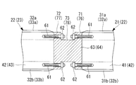
- FIG. FIG. 4 is an enlarged cross-sectional view
- FIG. 4 is a cross-sectional view showing a state after the completion of the assembly of the wind turbine rotor blade according to the present embodiment
- FIG. 5 is a cross-sectional view showing a state after the assembly of the wind turbine rotor blade according to another embodiment
- 6 is a sectional view taken along arrow VI-VI in FIG.
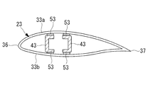
- FIG. 7 is a sectional view taken along arrow VII-VII in FIG. 2
- FIG. 8 is a sectional view taken along arrow VIII-VIII in FIG. It is a figure which shows the 1st coupling member which couple
- (a) is a figure which shows the flange shape seen from the 2nd main girder side
- (b) is a side view
- ( c) is a diagram showing a flange shape viewed from the first main beam side
- FIG. 10 is a diagram showing a second coupling member that couples the second main beam and the third main beam
- a) is a diagram showing FIG.
- the (b) is a side view
- (c) is a flange shape viewed from the side of the second main beam showing a flange shape viewed from the third main beam side of the.
- a wind turbine 1 for wind power generation includes a support column 3 standing on a foundation 2, a nacelle 4 installed at the upper end of the support column 3, and a nacelle 4 that is rotatable around a substantially horizontal axis. And a plurality of, for example, three windmill rotor blades 6 mounted radially around the rotation axis of the rotor hub 5. The wind force applied to the wind turbine rotor blade 6 from the direction of the rotation axis of the rotor hub 5 is converted into power for rotating the rotor hub 5 around the rotation axis.
- an anemometer 7 for measuring the peripheral wind speed value At the upper part of the nacelle 4, an anemometer 7 for measuring the peripheral wind speed value, an anemometer 8 for measuring the wind direction, and a lightning rod (not shown) are provided.
- a generator connected to the rotor hub 5 via a coaxial gearbox is installed inside the nacelle 4, although not shown in the drawings. In other words, the generator output is obtained from the generator by driving the generator by increasing the rotation of the rotor hub 5 with a speed increaser.
- the wind turbine rotor blade 6 has a skin 11 that defines a long hollow blade shape, and a longitudinal passage in the longitudinal direction inside the skin 11 to reinforce the strength of the skin 11.
- a girder (girder: spar) 12 is provided, and is at least divided into two (three in this embodiment) in the longitudinal direction. That is, the wind turbine rotor blades 6 are arranged in order from the blade root side (right side in FIG. 2) to the blade top side (left side in FIG. 2), the first blade 21, the second blade 22, and the third blade. 23.
- the outer skin 11 includes a first outer skin (main body outer skin) 31 that forms (configures) the first wing 21, a second outer skin (main body outer skin) 32 that forms (configures) the second wing 22, and a third A third outer skin 33 (main body outer skin) 33 that forms (composes) the wings 23, a first coupling portion outer skin 34, and a second coupling portion outer skin 35.
- the first outer skin 31, the second outer skin 32, the third outer skin 33, the first connecting portion outer skin 34, and the second connecting portion outer skin 35 are respectively formed from two halves of the back side skin and the ventral side skin. It has become.
- the suffix “a” or “b” is added to the reference numeral of the second coupling portion outer skin 35 for illustration. That is, the suffix “a” indicates the dorsal outer skin, and the suffix “b” indicates the ventral outer skin.
- first outer skin 31, the second outer skin 32, the third outer skin 33, the first coupling portion outer skin 34, and the second coupling portion outer skin 35 are formed of glass fiber reinforced plastic.
- first outer skin 31, the second outer skin 32, the third outer skin 33, the first coupling portion outer skin 34, and the second coupling portion outer skin 35 for example, carbon fiber reinforced plastic may be used. It is also possible to use other materials. When a carbon fiber reinforced plastic having high strength and rigidity is used, it is possible to easily cope with an increase in size of the wind turbine rotor blade 6.
- the main girder 12 forms a first main girder 41 that forms (configures) the first wing 21, a second main girder 42 that forms (configures) the second wing 22, and a third wing 23. It consists of a third main girder 43 to be configured.
- the first main girder 41 has a hollow cylindrical shape in cross section, and is bonded to the inner surface of the first outer skin 31 via the first reinforcing layer 51.
- the cross section 42 has a hollow prism shape and is bonded to the inner surface of the second outer skin 32 via the second reinforcing layer 52. Further, as shown in FIG.
- the third main girder 43 has a U-shaped cross-sectional shape and is attached to the inner surface of the third outer skin 33 so that the open portions thereof face each other.
- the first main beam 41, the second main beam 42, and the third main beam 43 are made of glass fiber reinforced plastic.
- a carbon fiber reinforced plastic may be used, for example, and another material may be used.
- a carbon fiber reinforced plastic having high strength and rigidity is used, it is possible to easily cope with an increase in size of the wind turbine rotor blade 6.
- the reinforcing layer 52, the third reinforcing layer 53 interposed between the third outer skin 33 and the third main girder 43 are each formed of glass fiber reinforced plastic and integrated with the corresponding outer skin and main girder. It is configured.
- a carbon fiber reinforced plastic may be used, for example, and another material may be used.
- the reinforcing layer 51, the reinforcing layer 52, and the reinforcing layer 53 may be configured only by a resin adhesive (resin layer).
- the first wing 21 and the second wing 22 are made of metal (for example, carbon steel, high-tensile steel, stainless steel, etc.) anchor bolts (or stud bolts) 61 and metal.
- anchor bolts or stud bolts
- metal for example, carbon steel, high-tensile steel, stainless steel, etc.
- first coupling member joint member
- the second wing 22 and the third wing 23 are joined to each other.
- the anchor bolt 61 made of metal (for example, carbon steel, high-tensile steel, stainless steel, etc.) and the metal (for example, carbon steel, high-tensile)
- the nut 62 made of steel, stainless steel, or the like and a second coupling member (joint member) 64 made of metal (for example, carbon steel, high-tensile steel, stainless steel, etc.) are joined to each other.
- the anchor bolt 61 extends from an end surface on the blade root side of the second main beam 42 toward an end surface on the blade root side of the second main beam 42 facing from the end surface on the blade top side of the first main beam 41. From the end surface on the blade top side of the second main girder 42 toward the end surface on the blade root side of the third main beam 43 facing each other, toward the end surface on the blade top side of the first main beam 41 facing each other.
- the first main girder 41 made of fiber-reinforced plastic is erected from the blade root side end surface of the third main girder 43 toward the blade top side end surface of the opposing second main girder 42.
- Each book (eight in this embodiment) is embedded.
- a female screw portion (not shown) that is screwed with a male screw portion (not shown) formed on the outer peripheral surface of the anchor bolt 61 is formed.
- the first coupling member 63 has a first flange portion 71 having a circular outer shape on the side joined to the first main beam 41, and the second main beam. 42 has a second flange portion 72 whose outer shape is rectangular, and a connecting portion 73 that connects the first flange portion 71 and the second flange portion 72. .
- the end face of the first flange part 71 has the same shape and the same dimensions as the end face on the blade top side of the first main girder 41 and is in close contact with the entire end face on the blade top side of the first main girder 41.
- a flange surface 71a is formed.
- an anchor bolt 61 that penetrates in the plate thickness direction and corresponds to a position corresponding to the anchor bolt 61 that is erected on the blade top end face of the first main girder 41 is provided.
- the through-holes 71b to be inserted are provided at equal intervals along the circumferential direction (45-degree intervals in the present embodiment).
- the end face of the second flange portion 72 has the same shape and the same dimensions as the end face on the blade root side of the second main girder 42 and is in close contact with the entire end face on the blade root side of the second main girder 42.
- a flange surface 72a is formed.
- anchor bolts 61 corresponding to penetrating in the plate thickness direction are provided at positions corresponding to the anchor bolts 61 erected on the blade root side end face of the second main girder 42.
- a through-hole 72b to be inserted is provided along the circumferential direction.
- the second coupling member 64 has a first flange portion 76 having a rectangular outer shape on the side joined to the second main girder 42, and has a third main girder.
- 43 has a second flange portion 77 whose outer shape is rectangular, and a connecting portion 78 that connects the first flange portion 76 and the second flange portion 77.
- the end face of the first flange portion 76 has the same shape and the same dimensions as the end face on the blade top side of the second main girder 42 and is in close contact with the entire end face on the blade top side of the second main girder 42.
- a flange surface 76a is formed.
- first flange portion 76 has an anchor bolt 61 corresponding to penetrating in the plate thickness direction at a position corresponding to the anchor bolt 61 erected on the end surface on the blade top side of the second main girder 42.
- a through hole 76b to be inserted is provided along the circumferential direction.
- the end face of the second flange portion 77 has the same shape and the same dimensions as the end face on the blade top side of the third main girder 43 and is in close contact with the entire end face on the blade root side of the third main girder 43.
- a flange surface 77a is formed.
- anchor bolts 61 corresponding to penetrating in the plate thickness direction are provided at positions corresponding to the anchor bolts 61 erected on the blade root side end face of the third main girder 43.
- a through hole 77b to be inserted is provided along the circumferential direction.
- the first flange portion 71 in contact with the inner surface of the back-side coupling portion skin 34a (35a) when the back-side coupling portion skin 34a (35a) is attached.
- 76 and the back surface (top surface) of the second flange portion 72 (77) and the inner side surface of the abdominal coupling portion skin 34b (35b) when the abdominal coupling portion skin 34b (35b) is attached.
- At least one recess 80 for receiving the tip of a countersunk screw (fastening member) 79 to be fixed (attached) is provided.
- a female screw portion (not shown) is formed which is screwed with a male screw portion 79a formed on the outer peripheral surface of the tip of the countersunk screw 79.
- the inner side surface of the coupling portion outer skin 34a (35a) on the back side and the back surfaces of the first flange portion 71 (76) and the second flange portion 72 (77) are in surface contact.
- Part (location), inner surface of the coupling portion outer skin 34a (35a) on the back side, outer surface of the first outer skin 31a on the back side, outer surface of the second outer skin 32a on the back side, third side on the back side The portion (location) where the outer surface of the outer skin 33a comes into surface contact, the inner surface of the abdominal coupling portion outer skin 34b (35b), the first flange portion 71 (76) and the second flange portion 72 (77).
- both end portions of the dorsal coupling portion skin 34 a (35 a) and both end portions of the abdominal coupling portion skin 34 b (35 b) The blade root side end of the second main girder 42 and the blade top side end, and the blade root side end of the third main girder 43 via a countersunk screw (fastening member) 81. Is (fixed).
- the inner surface of the back coupling portion outer skin 34a (35a) and the back surfaces of the first flange portion 71 (76) and the second flange portion 72 (77) are in surface contact.
- An adhesive (not shown) is applied to the portion (location) where the outer surface of the third outer skin 33b on the ventral side comes into surface contact.
- the girders 31, 32, 33 that are the main strength members of the divided blades 21, 22, 23 are coupled by the metal coupling members 63, 64. Therefore, even if the wing is enlarged, sufficient strength at the joint can be ensured without a significant increase in weight.
- the first blade 21, the second blade 22, the third blade 23, the first coupling portion outer skin 34, The second coupling portion skin 35, the first coupling member 63, and the second coupling member 64 separately or the first coupling member 63 is attached to the first wing 21 or the second wing 22, and the second In the state where the coupling members 64 are attached to the second wing 22 or the third wing 23, they are separately carried (conveyed) to the installation site of the wind turbine 1 for wind power generation.
- the coupling members 64 are attached to the second wing 22 or the third wing 23
- they are separately carried (conveyed) to the installation site of the wind turbine 1 for wind power generation.
- the end of the main girder 42 on the blade root side is easily coupled (assembled) via a first coupling member 63 that is coupled with a bolt and a nut, and the second main girder 42 of the second wing 22 is assembled.
- the end portion on the blade top side and the end portion on the blade root side of the third main girder 43 of the third blade 23 are easily coupled via a second coupling member 64 that is bolt-nut coupled. Therefore, the maintainability such as the ease of assembly and disassembly can be improved.
- the end face shapes of the first flange portions 71 and 76 and the second flange portions 72 and 77 are respectively the blade tops of the first main girder 41 facing each other. Because it has the same shape as the end face side, the blade root side end of the second main girder 42, the blade top side end, and the blade root side end of the third main girder 43. , Coupling member 63, 64 and the corresponding end of the first main girder 41 on the blade top side, the end of the second main girder 42 on the blade root side and the end of the blade top side, The end of the main girder 43 on the blade root side is smoothly connected, and the load can be transmitted efficiently.
- the coupling portion outer skins 34, 35 are connected to the back surfaces of the first flange portions 71, 76 and the second flange portions 72, 77 via the countersunk screws 79.
- it since it will be firmly fixed to the abdominal surface, the back surface and the abdominal surface of the third girder 43, it is possible to prevent peeling of the connecting portion outer skins 34 and 35.
- the wind turbine rotor blade 6 that can prevent breakage at the joint portion is provided, the wind turbine rotor blade accompanying the increase in size of the wind turbine 1 for wind power generator. 6 can also be accommodated.
- the present invention is not limited to the above-described embodiments, and various changes and modifications can be made without departing from the gist of the present invention.
- a metal hole for example, carbon steel, high-tensile steel, stainless steel, etc.
- a pilot hole 84 FIG. 11B
- FIG. 11B shows a state in which the first coupling member 63 is attached (fixed) to the blade root side end of the second main girder 42. Further, by inserting (interposing) an adhesive (resin) into the gap between the nut 85 and the pilot hole 84, the nut 85 can be securely fixed to the pilot hole 84. The omission of 85 can be reliably prevented.
- the blade end side end of the first main girder 41 molded (manufactured) as the first main girder 41, the second main girder 42, and the third main girder 43, the second main girder 42 The blade root side end and blade tip side end, the blade root side end of the third main girder 43, and the positions corresponding to the through holes 71b, 72b, 76b, 77b are shown in FIG.
- a metal e.g., carbon steel, high-tensile steel, stainless steel, etc.
- the lower hole 90 that accommodates an elongated (substantially) conical insert member 91 is provided in the longitudinal direction of the main girders 41, 42, 43.
- the insert member 91 is pre-embedded (screwed) into the pilot hole 90 in advance along the direction, and the coupling members 63 and 64 are connected to the end of the first main beam 41 on the blade top side, the second main beam.
- the anchor Before attaching (fixing) the blade root side end portion and blade top side end portion of 42 to the blade root side end portion of the third main girder 43, the anchor is fixed.
- a male screw portion 86 a formed on the outer peripheral surface of one end of the bolt (or stud bolt) 86 is screwed into a female screw portion 91 a formed on the inner peripheral surface of a bolt hole provided along the longitudinal direction of the insert member 91.
- FIG. 12 shows a state in which the first coupling member 63 is attached (fixed) to the blade root side end of the second main girder 42.
- a male screw portion (not shown) is formed on the outer peripheral surface of the insert member 91, and the male screw portion bites into the inner peripheral surface of the pilot hole 90, and the insert member 91 is It is difficult to remove from the pilot hole 90. Further, by inserting (interposing) an adhesive (resin) into the gap between the insert member 91 and the pilot hole 90, the insert member 91 can be securely fixed to the pilot hole 90. It is possible to reliably prevent the insert member 91 from coming off.
- the nut 85 as shown in FIG. 11 or the insert member 91 as shown in FIG. 12 is preliminarily attached to the blade top side end of the first main girder 41, the blade root side end of the second main girder 42, and the blade.
- the anchor bolt 86 is more reliably prevented from coming out in the axial direction (longitudinal direction of the wind turbine rotor blade 6). Therefore, the reliability of the wind turbine rotor blade 6 can be further improved.
- a metal lightning strip (receptor) 95 disposed on the tip and / or back and / or abdominal surface of the wind turbine rotor blade 6 and the coupling members 63 and 64 are connected by a conductive cable 96.
- the first coupling member 63 and the second coupling member 64 are connected by a (first) down conductor 97, and the first coupling member 63 and the rotor hub 5 are coupled by a (second) down conductor 98. It is more preferable to connect them. Since the rotor hub 5 is further electrically grounded via a slip ring, a bearing, a tower, etc.
- the potential difference between the air around the wind turbine rotor 6 and the ground on which the foundation 2 is installed is eliminated, and lightning strikes. Even when a lightning strike occurs, the conductive cable 96, the down conductors 97 and 98, and the ground line serve as a current path, and damage to the wind turbine rotor 6 and the wind turbine 1 for wind power generation can be prevented. . Further, by using the coupling members 63 and 64 as electrical contacts of the divided blades, a circuit can be easily and reliably formed when the blades are coupled.
- the metal lightning strip (receptor) 95, the conductive cable 96, the coupling members 63 and 64, and the down conductors 97 and 98 are coated with a resin or the like with respect to the internal space of the wing or painted with a paint. It is preferable that the lightning current be prevented from flowing out of the circuit.
Landscapes
- Engineering & Computer Science (AREA)
- Life Sciences & Earth Sciences (AREA)
- Sustainable Development (AREA)
- Sustainable Energy (AREA)
- Chemical & Material Sciences (AREA)
- Combustion & Propulsion (AREA)
- Mechanical Engineering (AREA)
- General Engineering & Computer Science (AREA)
- Wind Motors (AREA)
Priority Applications (4)
| Application Number | Priority Date | Filing Date | Title |
|---|---|---|---|
| CN201180050903.5A CN103180609B (zh) | 2010-10-22 | 2011-06-29 | 风车旋转叶片 |
| EP11834100.7A EP2631478A4 (de) | 2010-10-22 | 2011-06-29 | Rotorschaufel einer windturbine |
| KR1020137010067A KR20130069817A (ko) | 2010-10-22 | 2011-06-29 | 풍차 회전 날개 |
| US13/208,558 US8376713B2 (en) | 2010-10-22 | 2011-08-12 | Wind turbine rotor blade |
Applications Claiming Priority (2)
| Application Number | Priority Date | Filing Date | Title |
|---|---|---|---|
| JP2010237346A JP4939640B2 (ja) | 2010-10-22 | 2010-10-22 | 風車回転翼 |
| JP2010-237346 | 2010-10-22 |
Related Child Applications (1)
| Application Number | Title | Priority Date | Filing Date |
|---|---|---|---|
| US13/208,558 Continuation US8376713B2 (en) | 2010-10-22 | 2011-08-12 | Wind turbine rotor blade |
Publications (1)
| Publication Number | Publication Date |
|---|---|
| WO2012053258A1 true WO2012053258A1 (ja) | 2012-04-26 |
Family
ID=45974984
Family Applications (1)
| Application Number | Title | Priority Date | Filing Date |
|---|---|---|---|
| PCT/JP2011/064970 Ceased WO2012053258A1 (ja) | 2010-10-22 | 2011-06-29 | 風車回転翼 |
Country Status (6)
| Country | Link |
|---|---|
| US (1) | US8376713B2 (de) |
| EP (1) | EP2631478A4 (de) |
| JP (1) | JP4939640B2 (de) |
| KR (1) | KR20130069817A (de) |
| CN (1) | CN103180609B (de) |
| WO (1) | WO2012053258A1 (de) |
Families Citing this family (59)
| Publication number | Priority date | Publication date | Assignee | Title |
|---|---|---|---|---|
| CA2781551A1 (en) * | 2009-11-24 | 2011-06-03 | David E. Ronner | Wind turbine blade and methods, apparatus and materials for fabrication in the field |
| US9388789B2 (en) * | 2009-12-02 | 2016-07-12 | Vestas Wind Systems A/S | Sectional wind turbine blade |
| US20120141287A1 (en) * | 2011-08-29 | 2012-06-07 | General Electric Company | Wind turbine rotor blade joint |
| FR2980246B1 (fr) * | 2011-09-20 | 2018-08-17 | Arianegroup Sas | Dispositif de liaison de troncons d'ailes et procede d'assemblage de tels troncons |
| DE102011088025A1 (de) * | 2011-12-08 | 2013-06-13 | Wobben Properties Gmbh | Rotorblatt |
| IN2012DE00572A (de) * | 2012-02-29 | 2015-06-05 | Gen Electric | |
| US20140119926A1 (en) * | 2012-10-31 | 2014-05-01 | General Electric Company | Wind turbine rotor blade assembly with a ring insert in the blade root |
| US9790919B2 (en) | 2014-02-25 | 2017-10-17 | General Electric Company | Joint assembly for rotor blade segments of a wind turbine |
| WO2015155079A1 (de) | 2014-04-07 | 2015-10-15 | Wobben Properties Gmbh | Rotorblatt einer windenergieanlage |
| EP2930350B1 (de) | 2014-04-11 | 2018-02-14 | Siemens Aktiengesellschaft | Segmentierte Rotorschaufel mit Schraubverbindung |
| WO2015181401A1 (es) * | 2014-05-29 | 2015-12-03 | Nabrawind Sl | Union atornillada para pala modular |
| GB2527035A (en) * | 2014-06-05 | 2015-12-16 | Vestas Wind Sys As | Improvements relating to wind turbine blades |
| KR20170086071A (ko) | 2014-11-14 | 2017-07-25 | 글로벌 라이트닝 프로텍션 서비시즈 에이/에스 | 풍력 터빈 블레이드용 피뢰 시스템을 위한 완전 절연 팁 유닛 및 이를 포함하는 풍력 터빈 블레이드 |
| WO2017092766A1 (en) * | 2015-11-30 | 2017-06-08 | Vestas Wind Systems A/S | Wind turbines, wind turbine blades, and methods for manufacturing wind turbine blades |
| DK3441561T3 (da) * | 2016-04-04 | 2023-06-12 | Nabrawind Tech Sl | Indretning til sammenføjning af et modulært blad |
| US10550823B2 (en) * | 2016-08-10 | 2020-02-04 | General Electric Company | Method for balancing segmented wind turbine rotor blades |
| KR101954775B1 (ko) * | 2016-11-30 | 2019-05-17 | 두산중공업 주식회사 | 멀티 다운 컨덕터가 적용된 풍력 발전기용 카본 블레이드. |
| US10563636B2 (en) | 2017-08-07 | 2020-02-18 | General Electric Company | Joint assembly for a wind turbine rotor blade |
| WO2019091533A1 (en) * | 2017-11-13 | 2019-05-16 | Vestas Wind Systems A/S | Wind turbine blade assembly |
| CN108087191B (zh) * | 2017-12-25 | 2020-01-31 | 江苏金风科技有限公司 | 分段叶片、连接分段叶片的方法和风力发电机组 |
| DE102018112833A1 (de) * | 2018-05-29 | 2019-12-05 | Wobben Properties Gmbh | Windenergieanlagen-Rotorblatt |
| CN108843509A (zh) * | 2018-07-17 | 2018-11-20 | 芜湖超源力工业设计有限公司 | 一种新型风力发电机 |
| US10830207B2 (en) | 2018-08-28 | 2020-11-10 | General Electric Company | Spar configuration for jointed wind turbine rotor blades |
| DE102018121190A1 (de) * | 2018-08-30 | 2020-03-05 | Wobben Properties Gmbh | Rotorblatt, Windenergieanlage und Verfahren zum Optimieren einer Windenergieanlage |
| AU2018446413A1 (en) | 2018-10-25 | 2021-05-27 | General Electric Renovables España, S.L. | Spar cap configuration for a jointed wind turbine blade |
| GB201817599D0 (en) * | 2018-10-29 | 2018-12-12 | Blade Dynamics Ltd | Manufacturing of segmented wind turbine blade |
| GB201817618D0 (en) * | 2018-10-29 | 2018-12-12 | Blade Dynamics Ltd | Sealing member for a sectioned wind turbine blades |
| ES2961057T3 (es) | 2018-10-31 | 2024-03-07 | General Electric Renovables Espana Sl | Pala de rotor de turbina eólica unida ("jointed") que tiene combinaciones de materiales distintos a lo largo de su envergadura ("span") para refuerzo con pasadores |
| CN112912618B (zh) | 2018-11-01 | 2024-07-12 | 通用电气可再生能源西班牙有限公司 | 用于连结转子叶片节段的展向延伸销 |
| CN112912614A (zh) | 2018-11-01 | 2021-06-04 | 通用电气公司 | 用于将衬套安装并且固持于转子叶片接头的承载块中的方法 |
| WO2020091791A1 (en) * | 2018-11-01 | 2020-05-07 | General Electric Company | Spacer material for reducing a bond gap between a beam structure and a blade shell of a segmented rotor blade |
| US11828264B2 (en) | 2018-11-01 | 2023-11-28 | General Electric Company | Compliant structures for jointed rotor blades |
| WO2020091784A1 (en) * | 2018-11-01 | 2020-05-07 | General Electric Company | Wind turbine jointed rotor blade having a hollow chord-wise extending pin |
| EP3874140A1 (de) | 2018-11-01 | 2021-09-08 | General Electric Company | Stumpfverbindung für eine windturbinenrotorschaufel |
| EP3653871A1 (de) * | 2018-11-14 | 2020-05-20 | Winfoor AB | Kupplungsanordnung |
| EP3894194A1 (de) | 2018-12-11 | 2021-10-20 | General Electric Company | Verfahren zur herstellung einer hohlen verbundstruktur, insbesondere eines holmträgers für eine windturbinenlaufschaufel, und zugehöriger dorn |
| CN113165285A (zh) | 2018-12-11 | 2021-07-23 | 通用电气公司 | 用于制造用于风力涡轮的转子叶片的叶片节段的结构构件的方法 |
| JP7234371B2 (ja) | 2018-12-11 | 2023-03-07 | ゼネラル・エレクトリック・カンパニイ | 遷移形状を有するセグメント化されたロータブレード用のビーム構造 |
| CN113165288B (zh) | 2018-12-11 | 2023-06-20 | 通用电气公司 | 用于制造用于风力涡轮的转子叶片的叶片节段的结构构件的方法 |
| WO2020122864A1 (en) | 2018-12-11 | 2020-06-18 | General Electric Company | Methods for manufacturing blade components for wind turbine rotor blades |
| WO2020122909A1 (en) | 2018-12-13 | 2020-06-18 | General Electric Company | Jointed rotor blade having a chord-wise extending pin supported via one or more structural members |
| WO2020119874A1 (en) | 2018-12-14 | 2020-06-18 | Vestas Wind Systems A/S | Wind turbine blade |
| DK3899246T3 (da) | 2018-12-19 | 2024-05-06 | Lm Wind Power As | Segmenteret rotorvinge med indvendig støttestruktur med varierende fiberorientering til stiftforstærkning |
| EP3899244B1 (de) | 2018-12-20 | 2025-10-01 | General Electric Renovables España, S.L. | Zusammengefügtes windturbinenrotorblatt mit holmkappe, die aus unterschiedlichen formen von materialien entlang ihrer spannweite konstruiert ist |
| EP3899243B1 (de) | 2018-12-20 | 2024-04-10 | LM Wind Power A/S | Rotorblattsegmente, die über innere stützstrukturen miteinander verbunden sind, die einen variablen spalt dazwischen definieren |
| AU2020232943A1 (en) | 2019-03-01 | 2021-09-23 | General Electric Renovables España, S.L. | Jointed wind turbine rotor blade with chord-wise extending pin bushings designed to minimize chord-wise gap |
| WO2021018362A1 (en) | 2019-07-30 | 2021-02-04 | Vestas Wind Systems A/S | Connection for split wind turbine blade |
| WO2021021160A1 (en) * | 2019-07-31 | 2021-02-04 | General Electric Company | System and method for servicing a jointed rotor blade of a wind turbine |
| US12385465B2 (en) | 2020-08-28 | 2025-08-12 | Vestas Wind Systems A/S | Connection joint for a split wind turbine blade |
| GB202013647D0 (en) | 2020-08-31 | 2020-10-14 | Lm Wind Power As | Jointed wind turbine blade having improved transitions between varying material combinations |
| ES2977311T3 (es) * | 2021-01-27 | 2024-08-21 | Nordex Energy Se & Co Kg | Pala de rotor de aerogenerador |
| WO2023022715A1 (en) * | 2021-08-19 | 2023-02-23 | Lm Wind Power A/S | Winged spar cap configuration for a jointed wind turbine blade |
| CN113550862A (zh) * | 2021-08-20 | 2021-10-26 | 张效新 | 一种风力发电机组分段式叶片及叶片轴的连接方法 |
| CN113700599B (zh) * | 2021-09-18 | 2022-06-28 | 常州市宏发纵横新材料科技股份有限公司 | 一种高连接强度的复材分段式风电叶片 |
| WO2023046251A1 (en) * | 2021-09-22 | 2023-03-30 | Vestas Wind Systems A/S | Wind turbine blade with lightning protection system |
| JP7355142B1 (ja) * | 2022-03-17 | 2023-10-03 | 株式会社明電舎 | 風力発電装置のブレード用レセプタ |
| WO2023237166A1 (en) * | 2022-06-10 | 2023-12-14 | Vestas Wind Systems A/S | A pitch controlled wind turbine |
| CN119948255A (zh) * | 2022-09-20 | 2025-05-06 | 纳布拉温德科技有限公司 | 模块化叶片中的雷电保护装置 |
| EP4663942A1 (de) | 2024-06-12 | 2025-12-17 | Nordex Energy SE & Co. KG | Ein rotorblatt einer windkraftanlage mit wurzel-, haupt- und spitzenabschnitt |
Citations (3)
| Publication number | Priority date | Publication date | Assignee | Title |
|---|---|---|---|---|
| WO2005100781A1 (es) * | 2004-04-07 | 2005-10-27 | Gamesa Eólica, S.A., Sociedad Unipersonal | Pala para generadores eólicos |
| WO2008084126A1 (es) * | 2007-01-08 | 2008-07-17 | Guillermo Petri Larrea | Sistema reversible de seccionamiento en varias piezas de palas de aerogeneradores |
| JP2010059884A (ja) * | 2008-09-04 | 2010-03-18 | Mitsubishi Heavy Ind Ltd | 風車翼 |
Family Cites Families (9)
| Publication number | Priority date | Publication date | Assignee | Title |
|---|---|---|---|---|
| US1785318A (en) * | 1929-01-26 | 1930-12-16 | Dfan Mcg Gilfillan | Wing structure for airplanes |
| FR1187166A (fr) * | 1957-11-14 | 1959-09-08 | Perfectionnements apportés aux machines à pales, notamment aux éoliennes | |
| JP2000064941A (ja) * | 1998-08-19 | 2000-03-03 | Hitachi Zosen Corp | 風力発電装置 |
| JP2004011616A (ja) * | 2002-06-11 | 2004-01-15 | Shin Meiwa Ind Co Ltd | 風力発電機の風車ブレード構造 |
| CN2713072Y (zh) * | 2004-03-31 | 2005-07-27 | 厦门革新塑胶制品有限公司 | 折叠杆件连接件 |
| DK176176B1 (da) * | 2004-11-24 | 2006-11-27 | Siemens Wind Power As | Fremgangsmåde og samlestykke til samling af en vinge, fortrinsvis vindmöllevinge, i sektioner |
| JP4494499B2 (ja) * | 2007-08-01 | 2010-06-30 | ニッコー株式会社 | 水平軸風車のための筒状体及びその製造方法 |
| ES2337645B1 (es) | 2007-09-14 | 2011-03-11 | GAMESA INNOVATION & TECHNOLOGY, S.L. | Union de pala sensorizada. |
| CN201502483U (zh) * | 2009-07-13 | 2010-06-09 | 浙江恒通机械有限公司 | 一种风轮机叶片 |
-
2010
- 2010-10-22 JP JP2010237346A patent/JP4939640B2/ja not_active Expired - Fee Related
-
2011
- 2011-06-29 CN CN201180050903.5A patent/CN103180609B/zh not_active Expired - Fee Related
- 2011-06-29 EP EP11834100.7A patent/EP2631478A4/de not_active Withdrawn
- 2011-06-29 KR KR1020137010067A patent/KR20130069817A/ko not_active Ceased
- 2011-06-29 WO PCT/JP2011/064970 patent/WO2012053258A1/ja not_active Ceased
- 2011-08-12 US US13/208,558 patent/US8376713B2/en not_active Expired - Fee Related
Patent Citations (3)
| Publication number | Priority date | Publication date | Assignee | Title |
|---|---|---|---|---|
| WO2005100781A1 (es) * | 2004-04-07 | 2005-10-27 | Gamesa Eólica, S.A., Sociedad Unipersonal | Pala para generadores eólicos |
| WO2008084126A1 (es) * | 2007-01-08 | 2008-07-17 | Guillermo Petri Larrea | Sistema reversible de seccionamiento en varias piezas de palas de aerogeneradores |
| JP2010059884A (ja) * | 2008-09-04 | 2010-03-18 | Mitsubishi Heavy Ind Ltd | 風車翼 |
Also Published As
| Publication number | Publication date |
|---|---|
| EP2631478A4 (de) | 2014-05-07 |
| CN103180609B (zh) | 2015-11-25 |
| JP2012087753A (ja) | 2012-05-10 |
| US8376713B2 (en) | 2013-02-19 |
| CN103180609A (zh) | 2013-06-26 |
| JP4939640B2 (ja) | 2012-05-30 |
| US20120100002A1 (en) | 2012-04-26 |
| EP2631478A1 (de) | 2013-08-28 |
| KR20130069817A (ko) | 2013-06-26 |
Similar Documents
| Publication | Publication Date | Title |
|---|---|---|
| JP4939640B2 (ja) | 風車回転翼 | |
| JP5249684B2 (ja) | 風車翼 | |
| US8043065B2 (en) | Wind turbine blade with prefabricated leading edge segments | |
| US10830214B2 (en) | Method for securing a lightning receptor cable within a segmented rotor blade | |
| CN113056602B (zh) | 用于接合式风力涡轮转子叶片的翼梁构造 | |
| CA2894728C (en) | Wind blade tip joint | |
| US20120141287A1 (en) | Wind turbine rotor blade joint | |
| CN106286118B (zh) | 模块化风力涡轮转子叶片和其组装方法 | |
| CN103635306B (zh) | 包括在其根部区域中的圆柱形金属插入件的风力涡轮机叶片 | |
| EP3631198B1 (de) | Segmentiertes rotorblatt einer windturbine mit einer verbindungsanordnung aus geflanschten buchsen | |
| CN107191323A (zh) | 用于转子叶片段的螺栓接合 | |
| US11231010B2 (en) | Modular wind turbine blade | |
| EP3874141B1 (de) | Spannweitenweiser spreizstift zum verbinden von rotorblattsegmenten | |
| US12385465B2 (en) | Connection joint for a split wind turbine blade | |
| CN108138742A (zh) | 风能设备-转子叶片和风能设备 |
Legal Events
| Date | Code | Title | Description |
|---|---|---|---|
| 121 | Ep: the epo has been informed by wipo that ep was designated in this application |
Ref document number: 11834100 Country of ref document: EP Kind code of ref document: A1 |
|
| ENP | Entry into the national phase |
Ref document number: 20137010067 Country of ref document: KR Kind code of ref document: A |
|
| WWE | Wipo information: entry into national phase |
Ref document number: 2011834100 Country of ref document: EP |
|
| NENP | Non-entry into the national phase |
Ref country code: DE |