WO2012056830A1 - Véhicule utilitaire et son procédé de commande - Google Patents
Véhicule utilitaire et son procédé de commande Download PDFInfo
- Publication number
- WO2012056830A1 WO2012056830A1 PCT/JP2011/071301 JP2011071301W WO2012056830A1 WO 2012056830 A1 WO2012056830 A1 WO 2012056830A1 JP 2011071301 W JP2011071301 W JP 2011071301W WO 2012056830 A1 WO2012056830 A1 WO 2012056830A1
- Authority
- WO
- WIPO (PCT)
- Prior art keywords
- speed
- upper limit
- engine
- limit value
- clutch
- Prior art date
- Legal status (The legal status is an assumption and is not a legal conclusion. Google has not performed a legal analysis and makes no representation as to the accuracy of the status listed.)
- Ceased
Links
Images

Classifications
-
- E—FIXED CONSTRUCTIONS
- E02—HYDRAULIC ENGINEERING; FOUNDATIONS; SOIL SHIFTING
- E02F—DREDGING; SOIL-SHIFTING
- E02F9/00—Component parts of dredgers or soil-shifting machines, not restricted to one of the kinds covered by groups E02F3/00 - E02F7/00
- E02F9/20—Drives; Control devices
- E02F9/2058—Electric or electro-mechanical or mechanical control devices of vehicle sub-units
- E02F9/2095—Control of electric, electro-mechanical or mechanical equipment not otherwise provided for, e.g. ventilators, electro-driven fans
-
- E—FIXED CONSTRUCTIONS
- E02—HYDRAULIC ENGINEERING; FOUNDATIONS; SOIL SHIFTING
- E02F—DREDGING; SOIL-SHIFTING
- E02F3/00—Dredgers; Soil-shifting machines
- E02F3/04—Dredgers; Soil-shifting machines mechanically-driven
- E02F3/76—Graders, bulldozers, or the like with scraper plates or ploughshare-like elements; Levelling scarifying devices
- E02F3/7609—Scraper blade mounted forwardly of the tractor on a pair of pivoting arms which are linked to the sides of the tractor, e.g. bulldozers
-
- F—MECHANICAL ENGINEERING; LIGHTING; HEATING; WEAPONS; BLASTING
- F01—MACHINES OR ENGINES IN GENERAL; ENGINE PLANTS IN GENERAL; STEAM ENGINES
- F01P—COOLING OF MACHINES OR ENGINES IN GENERAL; COOLING OF INTERNAL-COMBUSTION ENGINES
- F01P7/00—Controlling of coolant flow
- F01P7/02—Controlling of coolant flow the coolant being cooling-air
- F01P7/04—Controlling of coolant flow the coolant being cooling-air by varying pump speed, e.g. by changing pump-drive gear ratio
- F01P7/044—Controlling of coolant flow the coolant being cooling-air by varying pump speed, e.g. by changing pump-drive gear ratio using hydraulic drives
-
- B—PERFORMING OPERATIONS; TRANSPORTING
- B60—VEHICLES IN GENERAL
- B60K—ARRANGEMENT OR MOUNTING OF PROPULSION UNITS OR OF TRANSMISSIONS IN VEHICLES; ARRANGEMENT OR MOUNTING OF PLURAL DIVERSE PRIME-MOVERS IN VEHICLES; AUXILIARY DRIVES FOR VEHICLES; INSTRUMENTATION OR DASHBOARDS FOR VEHICLES; ARRANGEMENTS IN CONNECTION WITH COOLING, AIR INTAKE, GAS EXHAUST OR FUEL SUPPLY OF PROPULSION UNITS IN VEHICLES
- B60K25/00—Auxiliary drives
- B60K25/02—Auxiliary drives directly from an engine shaft
- B60K2025/026—Auxiliary drives directly from an engine shaft by a hydraulic transmission
-
- B—PERFORMING OPERATIONS; TRANSPORTING
- B60—VEHICLES IN GENERAL
- B60W—CONJOINT CONTROL OF VEHICLE SUB-UNITS OF DIFFERENT TYPE OR DIFFERENT FUNCTION; CONTROL SYSTEMS SPECIALLY ADAPTED FOR HYBRID VEHICLES; ROAD VEHICLE DRIVE CONTROL SYSTEMS FOR PURPOSES NOT RELATED TO THE CONTROL OF A PARTICULAR SUB-UNIT
- B60W2510/00—Input parameters relating to a particular sub-units
- B60W2510/02—Clutches
- B60W2510/0208—Clutch engagement state, e.g. engaged or disengaged
- B60W2510/0233—Clutch engagement state, e.g. engaged or disengaged of torque converter lock-up clutch
-
- F—MECHANICAL ENGINEERING; LIGHTING; HEATING; WEAPONS; BLASTING
- F16—ENGINEERING ELEMENTS AND UNITS; GENERAL MEASURES FOR PRODUCING AND MAINTAINING EFFECTIVE FUNCTIONING OF MACHINES OR INSTALLATIONS; THERMAL INSULATION IN GENERAL
- F16H—GEARING
- F16H61/00—Control functions within control units of change-speed- or reversing-gearings for conveying rotary motion ; Control of exclusively fluid gearing, friction gearing, gearings with endless flexible members or other particular types of gearing
- F16H61/38—Control of exclusively fluid gearing
- F16H61/40—Control of exclusively fluid gearing hydrostatic
- F16H61/4165—Control of cooling or lubricating
Definitions
- the present invention relates to a work vehicle and a work vehicle control method.
- Cooling devices such as bulldozers are equipped with a cooling device for cooling the engine coolant.
- This cooling device has a cooling fan and a hydraulic motor.
- the hydraulic motor is driven by the hydraulic pressure supplied from the hydraulic pump, whereby the cooling fan rotates.
- the work vehicle includes a control unit that controls the number of rotations of the cooling fan. For example, as disclosed in Patent Document 1, the control unit sets the target rotational speed of the cooling fan (hereinafter referred to as “fan target rotational speed”) based on the temperature of the coolant and the temperature of the torque converter oil. Set. Further, the control unit sets an upper limit value of the fan target rotation speed in accordance with the engine rotation speed.
- the above-mentioned upper limit value of the fan target speed is uniformly determined according to the engine speed. For this reason, the upper limit value of the fan target speed is set regardless of the actual heat balance of the vehicle. For this reason, in order to avoid the situation where the cooling capacity is insufficient, it is desirable to set the upper limit value of the fan target rotational speed higher. For example, assuming the situation where the highest cooling capacity is required, the upper limit value of the fan target rotational speed is set so that sufficient cooling capacity can be exhibited even in such a situation.
- the actual situation of the work vehicle is not limited to the situation where the highest cooling capacity is required as described above. For this reason, the cooling capacity may become excessive. In this case, a part of the output of the engine is wasted for driving the cooling device.
- An object of the present invention is to provide a work vehicle and a work vehicle control method capable of improving fuel efficiency by suppressing an excessive cooling capacity.
- the work vehicle includes an engine, a traveling device, a power transmission device, a cooling fan, and a control unit.
- the traveling device is a device for traveling the vehicle.
- the power transmission device has a torque converter with a lock-up clutch and a transmission, and transmits driving force from the engine to the traveling device.
- the cooling fan cools the engine coolant and the power transmission fluid of the torque converter.
- the control unit sets an upper limit value of the fan target speed according to the engine speed. Further, the control unit reduces the upper limit value of the target fan speed when the lockup clutch is in an engaged state than when the lockup clutch is in an opened state.
- the work vehicle according to the second aspect of the present invention is the work vehicle according to the first aspect, and the control unit stores the first information and the second information.
- the first information is information indicating the relationship between the engine speed and the upper limit value of the fan target speed.
- the second information indicates the relationship between the engine speed and the upper limit value of the fan target speed, and is information for setting the upper limit value of the fan target speed lower than that of the first information.
- the control unit sets an upper limit value of the fan target speed based on the first information when the lockup clutch is in the released state. When the lockup clutch is in the engaged state, the control unit sets an upper limit value of the fan target speed based on the second information.
- a work vehicle is the work vehicle according to the second aspect, wherein the control unit locks up when the speed stage of the transmission is a predetermined speed stage higher than the minimum speed stage. Whether the clutch is in the engaged state or the released state, the upper limit value of the fan target speed is set based on the second information.
- a work vehicle control method is a work vehicle control method including an engine, a traveling device, a power transmission device, and a cooling fan.
- the traveling device is a device for traveling the vehicle.
- the power transmission device has a torque converter with a lock-up clutch and a transmission, and transmits driving force from the engine to the traveling device.
- the cooling fan cools the engine coolant and the power transmission fluid of the torque converter.
- the work vehicle control method includes a process of setting an upper limit value of the fan target speed according to the engine speed. In the process of setting the upper limit value of the fan target speed, the upper limit value of the fan target speed is reduced when the lockup clutch is in the engaged state than when the lockup clutch is in the released state.
- the lockup clutch when the lockup clutch is in the engaged state, the upper limit value of the fan target rotational speed is reduced compared to when the lockup clutch is in the released state.
- the lockup clutch When the lockup clutch is in the released state, the driving force from the engine is transmitted in the torque converter via the power transmission fluid of the torque converter. For this reason, the heat generation of the power transmission fluid of the torque converter is large.
- the lockup clutch when the lockup clutch is in the engaged state, the input shaft and the output shaft of the torque converter are directly connected via the lockup clutch. For this reason, the heat generation of the power transmission fluid of the torque converter is small.
- the cooling capacity for cooling the power transmission fluid of the torque converter may be smaller than when the lockup clutch is in the released state. For this reason, when the lockup clutch is in the engaged state, by reducing the upper limit value of the fan target rotation speed, it is possible to suppress the cooling capacity from becoming excessive and to improve the fuel efficiency.
- the upper limit value of the fan target rotational speed is set based on the first information. For this reason, high cooling capacity is securable by setting the upper limit of fan target number of rotations high.
- the upper limit value of the fan target speed is set based on the second information. For this reason, by setting the upper limit value of the fan target rotation number to be low, it is possible to suppress the cooling capacity from being excessive and to improve the fuel consumption.
- the upper limit value of the fan target rotational speed is based on the second information even if the lockup clutch is in the released state. Is set.
- the transmission speed stage is a high speed stage, it is easy to maintain a good heat balance of the work vehicle even if the cooling capacity of the cooling fan is low. For this reason, even if the lock-up clutch is in the released state, it is possible to prevent the cooling capacity from being insufficient. Moreover, fuel consumption can be improved by suppressing the cooling capacity of the cooling fan from becoming excessive.
- the lockup clutch when the lockup clutch is in the engaged state, the upper limit value of the fan target rotational speed is reduced compared to when the lockup clutch is in the released state.
- the lockup clutch When the lockup clutch is in the released state, the driving force from the engine is transmitted in the torque converter via the power transmission fluid of the torque converter. For this reason, the heat generation of the power transmission fluid of the torque converter is large.
- the lockup clutch when the lockup clutch is in the engaged state, the input shaft and the output shaft of the torque converter are directly connected via the lockup clutch. For this reason, the heat generation of the power transmission fluid of the torque converter is small.
- the cooling capacity for cooling the power transmission fluid of the torque converter may be smaller than when the lockup clutch is in the released state. For this reason, when the lock-up clutch is in the engaged state, by reducing the upper limit value of the fan target rotation speed, it is possible to suppress the cooling capacity from being excessive and to improve the fuel efficiency.
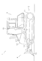
- FIG. 1 is a side view showing an external configuration of a work vehicle 1 according to an embodiment of the present invention.
- the work vehicle 1 is a bulldozer and includes left and right traveling bodies 2, a vehicle body 3, and a work implement 4.
- the traveling device 2 is a device for traveling the vehicle and has a crawler belt 11. When the crawler belt 11 is driven, the work vehicle 1 travels.
- the vehicle body 3 is disposed between the left and right traveling devices 2, and an engine room 12 is provided at the front of the vehicle body 3.
- the engine room 12 houses an engine 5 and a cooling device 7 which will be described later.
- a cab 15 is provided behind the engine room 12.
- the work machine 4 is provided in front of the engine room 12 and includes a blade 13 that is swingable in the vertical direction and a hydraulic cylinder 14 that drives the blade 13.
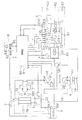
- the work vehicle 1 includes an engine 5, a power transmission device 6, a first hydraulic pump 16, a second hydraulic pump 17, a third hydraulic pump 19, a cooling device 7, an operating device 8, and various sensors SN1. -SN5 and control unit 9 are provided.
- the engine 5 is a diesel engine, and the output of the engine 5 is controlled by adjusting the fuel injection amount from a fuel injection pump (not shown). Adjustment of the fuel injection amount is performed by a control unit 9 controlling a governor (not shown).
- a governor an all-speed control type governor is generally used, and the engine speed and the fuel according to the load so that the actual engine speed becomes a command value of the engine speed set by the control unit 9. Adjust the injection amount. That is, the governor increases or decreases the fuel injection amount so that the difference between the engine speed command value and the actual engine speed is eliminated.
- the power transmission device 6 is a device that transmits the driving force from the engine 5 to the traveling device 2 described above.
- the power transmission device 6 includes a torque converter 60 with a lock-up clutch LC, a transmission 61, a final reduction device 62, and a sprocket 63.
- the output of the engine 5 is transmitted to the traveling device 2 described above via the torque converter 60, the transmission 61, the final reduction device 62, and the sprocket 63.
- the torque converter 60 is connected to the output shaft of the engine 5 via a PTO (power take-off device) shaft 18.
- the lockup clutch LC is switched between the engaged state and the released state by the hydraulic oil supplied from the third hydraulic pump 19.
- the lockup clutch LC When the lockup clutch LC is engaged, the input shaft and the output shaft of the torque converter 60 are directly connected.
- the torque converter 60 transmits the driving force via the torque converter oil as the power transmission fluid.
- the torque converter oil is hydraulic oil that is supplied from the third hydraulic pump 19 to the torque converter 60.
- the supply of hydraulic oil to the lockup clutch LC is controlled by a lockup solenoid valve LV controlled by a control signal from the control unit 9.
- the transmission 61 has a forward hydraulic clutch (hereinafter referred to as “F clutch”) C1 and a reverse hydraulic clutch (hereinafter referred to as “R clutch”) C2, and any of the F clutch C1 and the R clutch C2 Is selected, forward travel or reverse travel is performed.
- the F clutch C ⁇ b> 1 and the R clutch C ⁇ b> 2 are switched between the engaged state and the released state by the hydraulic fluid supplied from the third hydraulic pump 19.
- the transmission 61 includes a first speed hydraulic clutch (hereinafter referred to as “1st clutch”) C3, a second speed hydraulic clutch (hereinafter referred to as “2nd clutch”) C4, and a third speed hydraulic clutch (hereinafter referred to as “first clutch”). , Referred to as “3rd clutch”).
- first clutch a first speed hydraulic clutch
- second clutch a second speed hydraulic clutch
- third speed hydraulic clutch hereinafter referred to as “first clutch”.
- the supply of hydraulic oil to the first clutch C3 is controlled by the first speed solenoid valve V3, and the supply of hydraulic oil to the second clutch C4 is controlled by the second speed solenoid valve V4, and the operation to the 3rd clutch C5.
- the supply of oil is controlled by the third speed solenoid valve V5.
- These electromagnetic valves V3-V5 are controlled by a control signal from the control unit 9.
- the output of the engine 5 is transmitted to the sprocket 63 via the torque converter 60, the transmission 61, and the final reduction gear 62, and thereby the sprocket 63 is rotationally driven.
- the sprocket 63 is driven to rotate, the crawler belt 11 (see FIG. 1) wound around the sprocket 63 is driven, whereby the work vehicle 1 travels.
- a part of the horsepower of the engine 5 is consumed as a traveling horsepower for causing the work vehicle 1 to travel.
- the first hydraulic pump 16 is connected to the output shaft of the engine 5 via the PTO shaft 18 and is driven by the driving force from the engine 5.
- the first hydraulic pump 16 discharges hydraulic oil for driving the cooling device 7.
- the first hydraulic pump 16 is a variable displacement hydraulic pump, and the pump displacement is changed by changing the tilt angle of the swash plate by the swash plate drive unit 21.
- the swash plate driving unit 21 is controlled by a control signal from the control unit 9.
- the second hydraulic pump 17 is connected to the output shaft of the engine 5 through the PTO shaft 18 and is driven by the engine 5 to discharge hydraulic oil for driving the hydraulic cylinder 14 of the work machine 4.
- the second hydraulic pump 17 is a variable displacement hydraulic pump, and the pump displacement is changed by changing the tilt angle of the swash plate by the swash plate drive unit 29.
- the swash plate driving unit 29 is controlled by a control signal from the control unit 9.
- the cooling device 7 is a device that is driven by hydraulic oil supplied from the first hydraulic pump 16 and cools the engine 5.
- the cooling device 7 includes a hydraulic motor 71, a cooling fan 72, a radiator 73, a first oil cooler 76, and a second oil cooler 74.
- the hydraulic motor 71 is a hydraulic motor for the cooling fan 72.
- the hydraulic motor 71 is driven by the hydraulic oil discharged from the first hydraulic pump 16 and rotationally drives the cooling fan 72.
- An electromagnetic switching valve 75 is provided between the hydraulic motor 71 and the first hydraulic pump 16.
- the electromagnetic switching valve 75 is a two-position valve, and can switch the flow direction of the hydraulic oil by a command signal from the control unit 9, thereby controlling the rotation direction of the hydraulic motor 71, that is, the cooling fan 72. .
- the rotational speed of the hydraulic motor 71, that is, the rotational speed of the cooling fan 72 is controlled by controlling the pump capacity of the first hydraulic pump 16 by the swash plate driving unit 21.
- the cooling fan 72 is rotationally driven by the hydraulic motor 71 to generate an air flow through the radiator 73, the first oil cooler 76, and the second oil cooler 74.
- the radiator 73 is a device that cools the coolant of the engine 5.
- the radiator 73 receives the air flow generated by the cooling fan 72 and cools the coolant of the engine 5.
- the first oil cooler 76 is a device that cools the torque converter oil from the torque converter 60.
- the first oil cooler 76 receives the air flow generated by the cooling fan 72 and cools the torque converter oil.
- the hydraulic circuit for supplying torque converter oil to the torque converter 60 is partially common with the hydraulic circuit for supplying hydraulic oil to the hydraulic clutches C1-C5 of the transmission 61. is doing. Accordingly, the second oil cooler 74 also cools the hydraulic oil from the hydraulic clutch C1-C5 of the transmission 61.
- the second oil cooler 74 is a device that cools the hydraulic oil supplied to the hydraulic motor 71 of the cooling device 7.
- the second oil cooler 74 receives the air flow generated by the cooling fan 72 and cools the hydraulic oil from the hydraulic motor 71.
- the hydraulic oil from the hydraulic motor 71 enters the second oil cooler 74 via the electromagnetic switching valve 75, is cooled by the second oil cooler 74, and then returns to the hydraulic oil tank 22.
- the hydraulic oil from the hydraulic cylinder 14 of the work machine 4 is similarly cooled by the second oil cooler 74 and then returned to the hydraulic oil tank 22.
- the hydraulic oil stored in the hydraulic oil tank 22 is pressurized by the first hydraulic pump 16 and the second hydraulic pump 17 and supplied to the hydraulic motor 71 and the hydraulic cylinder 14, respectively.
- radiator 73 the first oil cooler 76, and the second oil cooler 74 may be formed separately. Alternatively, all or a part of the radiator 73, the first oil cooler 76, and the second oil cooler 74 may be integrally formed.
- the cooling fan 72 When hydraulic oil is supplied to the first hydraulic motor 71, the cooling fan 72 is driven to rotate, and an air flow that passes through the radiator 73, the first oil cooler 76, and the second oil cooler 74 is generated. Thereby, the coolant of the engine 5 that flows through the radiator 73, the torque converter oil that flows through the first oil cooler 76, and the hydraulic oil that flows through the second oil cooler 74 are cooled. Thus, part of the horsepower of the engine 5 is consumed as fan horsepower for driving the cooling device 7 that cools the coolant, torque converter oil, and hydraulic oil of the engine 5.
- the operating device 8 is built in the cab 15 and sends an operation signal to the control unit 9 when operated by an operator.
- the operating device 8 includes a shift switch 81, a travel lever 82, and the like.
- the shift switch 81 is for switching the speed stage of the transmission 61.
- the speed stage can be switched from the first speed to the third speed, and the speed stage can be manually switched by the operator operating the shift switch 81.
- the traveling lever 82 includes a forward / reverse lever member 84 and a turning lever member 85.
- the operator can switch the transmission 61 between the forward movement state, the reverse movement state, and the neutral state by operating the forward / reverse lever member 84. Further, the operator can switch the turning direction of the work vehicle 1 by operating the turning lever member 85.
- the various sensors SN1-SN5 include a first oil temperature sensor SN1, a coolant temperature sensor SN2, a second oil temperature sensor SN3, an engine speed sensor SN4, and a transmission speed sensor SN5.
- the first oil temperature sensor SN1 detects the temperature of hydraulic oil that drives the hydraulic motor 71 of the cooling device 7 and the hydraulic cylinder 14 of the work machine 4 (hereinafter referred to as “hydraulic oil temperature”).
- Coolant temperature sensor SN2 detects the temperature of the coolant of engine 5 (hereinafter referred to as “coolant temperature”).
- the second oil temperature sensor SN3 detects the temperature of the hydraulic oil for driving the hydraulic clutch C1-C5 of the transmission 61.
- the hydraulic circuit for supplying torque converter oil to torque converter 60 is partially in common with the hydraulic circuit for supplying hydraulic oil for operating hydraulic clutches C1-C5 of transmission 61. Yes. Therefore, the temperature of the hydraulic oil from the hydraulic clutch C1-C5 coincides with the temperature of the torque converter oil (hereinafter referred to as “torque converter oil temperature”). For this reason, the second oil temperature sensor SN3 detects the torque converter oil temperature.
- the engine speed sensor SN4 detects the engine speed that is the actual speed of the engine 5.
- Transmission speed sensor SN5 detects the speed of the output shaft of transmission 61 to detect the vehicle speed of work vehicle 1.
- Various types of information detected by these sensors SN1 to SN5 are input to the control unit 9 as detection signals.
- the control unit 9 is mainly composed of an arithmetic processing unit such as a microcomputer or a numerical arithmetic processor, and has a storage unit 90 for storing control data and the like.
- the control unit 9 is based on the operation signal from the operation device 8, the detection signal from the sensors SN1-SN5, the control data stored in the storage unit 90, and the like, the engine 5, the power transmission device 6, the cooling device 7, the work implement. 4 etc. are controlled.
- the storage unit 90 stores an engine power curve indicating the relationship between the engine speed and the engine torque, and the control unit 9 controls the engine 5 based on the engine power curve.
- control unit 9 switches the lock-up clutch LC of the torque converter 60 and the F-clutch of the transmission 61 automatically based on the vehicle speed and the engine speed or according to the operation of the shift switch 81 and the travel lever 82.
- the C1, R clutch C2, and shift clutch C3-C5 are switched.
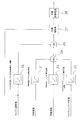
- FIG. 3 is a block diagram illustrating processing functions of the control unit 9.
- the control unit 9 controls the rotation speed of the cooling fan 72 based on the coolant temperature, the hydraulic oil temperature, the torque converter oil temperature, and the engine rotation speed.
- the control unit 9 includes a first target rotation number calculation unit 31, a second target rotation number calculation unit 32, a third target rotation number calculation unit 33, a maximum value selection unit 34, and an upper limit value calculation.
- the first target rotational speed calculation unit 31 refers to the map stored in the storage unit 90 and calculates the fan target rotational speed from the coolant temperature detected by the coolant temperature sensor SN2. In the map, the relationship between the coolant temperature at which the fan target speed increases as the coolant temperature increases and the fan target speed is set.
- the second target rotation speed calculation unit 32 calculates the fan target rotation speed of the cooling fan 72 from the temperature of the hydraulic oil detected by the first oil temperature sensor SN1 with reference to the map stored in the storage unit 90. To do. In the map of the storage unit 90, the relationship between the hydraulic oil temperature at which the fan target rotational speed increases as the hydraulic oil temperature increases and the fan target rotational speed is set.
- the third target rotational speed calculation unit 33 refers to the map stored in the storage unit 90 and calculates the fan target rotational speed of the cooling fan 72 from the torque converter oil temperature detected by the second oil temperature sensor SN3. To do.
- the map of the storage unit 90 the relationship between the torque converter oil temperature at which the fan target speed increases as the torque converter oil temperature increases and the fan target speed is set.
- the maximum value selection unit 34 includes a fan target rotation number calculated by the first target rotation number calculation unit 31, a fan target rotation number calculated by the second target rotation number calculation unit 32, and a third target rotation number calculation unit. The highest rotational speed among the fan target rotational speeds calculated by 33 is selected.
- the upper limit calculation unit 35 refers to the map stored in the storage unit 90 and calculates the upper limit value of the fan target rotation speed from the engine rotation speed detected by the engine rotation speed sensor SN4.
- the map of the storage unit 90 the relationship between the engine speed at which the upper limit value of the fan target speed increases as the engine speed increases and the upper limit value of the fan target speed is set. Therefore, the control unit 9 sets an upper limit value of the fan target speed according to the engine speed.
- the minimum value selection unit 36 selects the smaller rotation number between the fan target rotation number selected by the maximum value selection unit 34 and the upper limit value of the fan target rotation number calculated by the upper limit value calculation unit 35. Therefore, in the minimum value selector 36, the fan target speed is set so that the fan target speed selected by the maximum value selector 34 does not exceed the upper limit value of the fan target speed calculated by the upper limit calculator 35. It is corrected. The calculation of the upper limit value of the target fan speed by the upper limit calculation unit 35 will be described in detail later.
- the tilt angle calculator 37 is a first hydraulic pump for obtaining the target fan speed from the engine speed detected by the engine speed sensor SN4 and the fan target speed selected by the minimum value selector 36. Sixteen target tilt angles are calculated.
- the rotational speed of the cooling fan 72 is determined based on the rotational speed of the hydraulic motor 71.
- the rotational speed of the hydraulic motor 71 is determined by the flow rate of hydraulic oil supplied to the hydraulic motor 71.
- the flow rate of the hydraulic oil supplied to the hydraulic motor 71 corresponds to the discharge flow rate of the first hydraulic pump 16.
- the discharge flow rate of the first hydraulic pump 16 is determined by the tilt angle and the rotational speed of the first hydraulic pump 16.
- the rotational speed of the first hydraulic pump 16 is determined by the rotational speed of the engine 5. Therefore, if the engine speed is known, the target tilt angle of the first hydraulic pump 16 for obtaining the fan target speed can be calculated.
- the control current calculation unit 38 calculates a command signal value to the swash plate driving unit 21 for obtaining the target tilt angle calculated by the tilt angle calculation unit 37, that is, a target control current value.
- the control unit 9 outputs a control current corresponding to the target control current value obtained as described above to the swash plate driving unit 21.
- the upper limit calculator 35 calculates the upper limit value of the fan target speed from the engine speed.
- the upper limit calculation unit 35 refers to the map stored in the storage unit 90.
- the storage unit 90 stores a first map L1 and a second map L2 for calculating the upper limit value of the fan target rotation speed.
- the first map L1 and the second map L2 both show the relationship between the engine speed and the upper limit value of the fan target speed.
- the upper limit value of the fan target speed is constant at Nf1 when the engine speed ranges from zero to Ne1.
- the upper limit value of the fan target speed gradually increases as the engine speed increases.
- the upper limit value of the fan target speed is constant at Nf3.
- the upper limit value of the fan target rotational speed is constant at Nf1, as in the first map L1, in the range from the engine rotational speed of zero to Ne1.
- the upper limit value of the fan target speed gradually increases as the engine speed increases.
- Ne3 is larger than Ne2.
- the upper limit value of the fan target speed is constant at Nf2.
- Nf2 is smaller than Nf3.
- the second map L2 is defined such that the upper limit value of the fan target speed is set lower than that of the first map L1 if the engine speed is the same. .
- the difference between the upper limit value of the fan target speed of the first map L1 and the upper limit value of the fan target speed of the second map L2 increases as the engine speed increases. It ’s getting bigger.
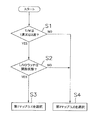
- the upper limit calculator 35 selects one of the first map L1 and the second map L2 as a map for calculating the upper limit value of the fan target rotation speed according to the flow shown in FIG.
- step S1 it is determined whether or not the speed stage of the transmission 61 is the first speed or the second speed.
- the process proceeds to step S4, and the second map L2 is selected.
- step S1 when the speed stage of the transmission 61 is the first speed or the second speed, the process proceeds to step S2.
- step S2 it is determined whether or not the lockup clutch LC is in the released state.
- step S3 When the lockup clutch LC is in the released state, the process proceeds to step S3, and the first map L1 is selected.
- step S4 When the lockup clutch LC is not in the released state in step S2, that is, when the lockup clutch LC is in the engaged state, the process proceeds to step S4, and the second map L2 is selected.
- the upper limit value calculation unit 35 determines whether or not the second map L2 regardless of whether the lockup clutch LC is in the engaged state or the released state. Based on the above, the upper limit value of the fan target speed is set. Even when the speed stage of the transmission 61 is the first speed or the second speed and the lock-up clutch LC is in the engaged state, the upper limit value calculation unit 35 performs the fan target rotation speed based on the second map L2. Set the upper limit of. However, when the speed stage of the transmission 61 is the first speed or the second speed and the lockup clutch LC is in the released state, the upper limit calculator 35 determines the fan target rotational speed based on the first map L1. Set the upper limit.
- the upper limit value of the fan target speed is set to be smaller than that in the first map L1. Therefore, when the speed stage of the transmission 61 is the first speed or the second speed, the upper limit calculation unit 35 determines the upper limit value of the fan target rotation speed when the lockup clutch LC is engaged as the lockup clutch. This is lower than the upper limit value of the fan target speed when the LC is in the open state.
- the work vehicle 1 and the method for controlling the work vehicle 1 according to the present embodiment have the following characteristics.
- the lockup clutch LC When the lockup clutch LC is in the engaged state, the upper limit value of the fan target speed is reduced compared to when the lockup clutch LC is in the released state.
- the lockup clutch LC When the lockup clutch LC is in the released state, the driving force from the engine 5 is transmitted in the torque converter 60 via the torque converter oil. For this reason, the heat generated by the torque converter oil is large.
- the lockup clutch LC when the lockup clutch LC is in the engaged state, the input shaft and the output shaft of the torque converter 60 are directly connected via the lockup clutch LC. For this reason, the heat generation of the torque converter oil is small. Therefore, when the lockup clutch LC is in the engaged state, the cooling capacity for cooling the torque converter oil may be smaller than when the lockup clutch LC is in the released state. For this reason, when the lock-up clutch LC is in the engaged state, by reducing the upper limit value of the fan target rotational speed, it is possible to suppress the cooling capacity from becoming excessive and improve the fuel efficiency.
- the upper limit value of the fan target rotational speed is set based on the first map L1.
- the upper limit value of the fan target speed is set higher than when the second map L2 is used. For this reason, a high cooling capacity can be ensured.
- the lockup clutch LC is in the engaged state, the upper limit value of the fan target speed is set based on the second map L2. For this reason, by setting the upper limit value of the fan target rotation number to be low, it is possible to suppress the cooling capacity from being excessive and to improve the fuel consumption.
- the upper limit value of the fan target speed is set based on the second map L2 even when the lockup clutch LC is in the released state.
- the speed stage of the transmission 61 is a high speed stage, it is easy to maintain a good heat balance of the work vehicle 1 even if the cooling capacity of the cooling fan 72 is low. For this reason, even if the lock-up clutch LC is in the released state, it is possible to prevent the cooling capacity from being insufficient. In addition, the cooling capacity of the cooling fan 72 can be suppressed from being excessive, and fuel consumption can be improved.
- a bulldozer is illustrated as the work vehicle 1, but the present invention may be applied to other work vehicles.
- a map is used as information indicating the relationship between the engine speed and the upper limit value of the fan target speed, but the information format is not limited to the map.
- a table or a calculation formula may be used as information indicating the relationship between the engine speed and the upper limit value of the fan target speed.
- the map used for calculating the upper limit value of the fan target speed is selected from the first map L1 and the second map L2, but may be selected from three or more maps.
- the second map L2 is selected regardless of the state of the lockup clutch LC.
- the speed stage of the transmission 61 is not limited to the third speed but is a predetermined high speed stage higher than the minimum speed stage
- the second map L2 is selected regardless of the state of the lockup clutch LC. May be.
- the second map L2 may be selected regardless of the state of the lockup clutch LC.
- the maximum speed stage of the transmission 61 is not limited to the third speed and may be the fourth speed or higher. Accordingly, when the speed stage of the transmission 61 is the fourth speed, or when the speed stage of the transmission 61 is the third speed or the fourth speed, the second speed is maintained regardless of the state of the lockup clutch LC.
- the map L2 may be selected.
- the present invention has an effect of improving fuel efficiency by suppressing the cooling capacity from becoming excessive. Therefore, the present invention is useful as a work vehicle and a work vehicle control method.
Landscapes
- Engineering & Computer Science (AREA)
- General Engineering & Computer Science (AREA)
- Mechanical Engineering (AREA)
- Mining & Mineral Resources (AREA)
- Civil Engineering (AREA)
- Structural Engineering (AREA)
- Chemical & Material Sciences (AREA)
- Combustion & Propulsion (AREA)
- Component Parts Of Construction Machinery (AREA)
- Control Of Fluid Gearings (AREA)
- Operation Control Of Excavators (AREA)
Abstract
L'invention porte sur une unité de commande, d'un véhicule utilitaire, qui fixe une valeur limite supérieure de la vitesse de rotation cible d'un ventilateur en fonction de la vitesse de rotation d'un moteur. Lorsqu'un embrayage de verrouillage est en prise, l'unité de commande réduit la valeur limite supérieure de la vitesse de rotation cible du ventilateur à une valeur plus faible que lorsque l'embrayage de verrouillage est libéré.
Priority Applications (2)
| Application Number | Priority Date | Filing Date | Title |
|---|---|---|---|
| CN201180005419.0A CN102695894B (zh) | 2010-10-26 | 2011-09-20 | 作业车辆及作业车辆的控制方法 |
| US13/514,540 US8662223B2 (en) | 2010-10-26 | 2011-09-20 | Work vehicle and method for controlling work vehicle |
Applications Claiming Priority (2)
| Application Number | Priority Date | Filing Date | Title |
|---|---|---|---|
| JP2010239227A JP5074571B2 (ja) | 2010-10-26 | 2010-10-26 | 作業車両および作業車両の制御方法 |
| JP2010-239227 | 2010-10-26 |
Publications (1)
| Publication Number | Publication Date |
|---|---|
| WO2012056830A1 true WO2012056830A1 (fr) | 2012-05-03 |
Family
ID=45993560
Family Applications (1)
| Application Number | Title | Priority Date | Filing Date |
|---|---|---|---|
| PCT/JP2011/071301 Ceased WO2012056830A1 (fr) | 2010-10-26 | 2011-09-20 | Véhicule utilitaire et son procédé de commande |
Country Status (4)
| Country | Link |
|---|---|
| US (1) | US8662223B2 (fr) |
| JP (1) | JP5074571B2 (fr) |
| CN (1) | CN102695894B (fr) |
| WO (1) | WO2012056830A1 (fr) |
Families Citing this family (10)
| Publication number | Priority date | Publication date | Assignee | Title |
|---|---|---|---|---|
| CN102910067B (zh) * | 2012-10-31 | 2015-04-08 | 中铁隧道股份有限公司 | 隧道施工内燃牵引机车液力变矩器的液压冷却控制方法 |
| US8973536B2 (en) * | 2013-01-25 | 2015-03-10 | Caterpillar Inc. | Engine compensation for fan power |
| JP6080630B2 (ja) * | 2013-03-19 | 2017-02-15 | 株式会社タダノ | 作業車両 |
| CN104271844B (zh) * | 2013-03-29 | 2015-08-26 | 株式会社小松制作所 | 推土机 |
| WO2015099448A1 (fr) * | 2013-12-26 | 2015-07-02 | 두산인프라코어 주식회사 | Dispositif de commande de puissance pour machine de construction |
| JP6630030B2 (ja) * | 2014-01-31 | 2020-01-15 | 株式会社小松製作所 | ホイールローダ及びホイールローダの制御方法 |
| JP6009480B2 (ja) | 2014-03-06 | 2016-10-19 | 日立建機株式会社 | 建設機械の冷却ファン制御装置 |
| CN105074157B (zh) * | 2015-03-27 | 2017-09-26 | 株式会社小松制作所 | 作业车辆 |
| JP6544322B2 (ja) * | 2016-09-05 | 2019-07-17 | 株式会社デンソー | 車両用灯具制御装置 |
| JP6520877B2 (ja) * | 2016-09-20 | 2019-05-29 | トヨタ自動車株式会社 | 車両走行制御装置 |
Citations (2)
| Publication number | Priority date | Publication date | Assignee | Title |
|---|---|---|---|---|
| JPH08135772A (ja) * | 1994-11-14 | 1996-05-31 | Toyota Motor Corp | 自動変速機における冷却および潤滑装置 |
| JP2001182535A (ja) * | 1999-12-22 | 2001-07-06 | Komatsu Ltd | 油圧駆動冷却ファン |
Family Cites Families (9)
| Publication number | Priority date | Publication date | Assignee | Title |
|---|---|---|---|---|
| US3059745A (en) * | 1960-03-31 | 1962-10-23 | Thompson Ramo Wooldridge Inc | Temperature and speed sensitive drive |
| US6129193A (en) * | 1997-08-29 | 2000-10-10 | American Cooling Systems, L.L.C. | Electric fan clutch |
| JP4204137B2 (ja) * | 1999-04-22 | 2009-01-07 | 株式会社小松製作所 | 冷却用ファンの駆動制御装置 |
| AU2005330847B2 (en) * | 2005-04-07 | 2009-07-02 | Hitachi Construction Machinery Co., Ltd. | Cooling device for construction machine |
| US7373239B2 (en) * | 2005-07-06 | 2008-05-13 | Komatsu, Ltd. | Engine control device of work vehicle |
| JP4573751B2 (ja) | 2005-11-02 | 2010-11-04 | 日立建機株式会社 | 走行式作業機械の冷却ファン駆動装置 |
| US8955472B2 (en) | 2007-06-25 | 2015-02-17 | Komatsu Ltd. | Work vehicle and control method for work vehicle |
| JP2009024592A (ja) * | 2007-07-19 | 2009-02-05 | Caterpillar Japan Ltd | 冷却ファン駆動装置 |
| US8109375B2 (en) * | 2009-05-07 | 2012-02-07 | Kit Masters Inc. | Clutch systems and methods |
-
2010
- 2010-10-26 JP JP2010239227A patent/JP5074571B2/ja active Active
-
2011
- 2011-09-20 US US13/514,540 patent/US8662223B2/en active Active
- 2011-09-20 CN CN201180005419.0A patent/CN102695894B/zh active Active
- 2011-09-20 WO PCT/JP2011/071301 patent/WO2012056830A1/fr not_active Ceased
Patent Citations (2)
| Publication number | Priority date | Publication date | Assignee | Title |
|---|---|---|---|---|
| JPH08135772A (ja) * | 1994-11-14 | 1996-05-31 | Toyota Motor Corp | 自動変速機における冷却および潤滑装置 |
| JP2001182535A (ja) * | 1999-12-22 | 2001-07-06 | Komatsu Ltd | 油圧駆動冷却ファン |
Also Published As
| Publication number | Publication date |
|---|---|
| US8662223B2 (en) | 2014-03-04 |
| JP5074571B2 (ja) | 2012-11-14 |
| US20120241235A1 (en) | 2012-09-27 |
| JP2012092691A (ja) | 2012-05-17 |
| CN102695894A (zh) | 2012-09-26 |
| CN102695894B (zh) | 2014-04-09 |
Similar Documents
| Publication | Publication Date | Title |
|---|---|---|
| JP5074571B2 (ja) | 作業車両および作業車両の制御方法 | |
| CN101784773B (zh) | 作业车辆及作业车辆的控制方法 | |
| US7373239B2 (en) | Engine control device of work vehicle | |
| US7841307B2 (en) | Cooling fan drive system for travel type working machine | |
| JP5032705B2 (ja) | エンジン回転数制御装置及びそれを有するモータグレーダ | |
| RU2499153C2 (ru) | Управление частотой вращения двигателя в машине | |
| JP5092060B1 (ja) | 作業車両及び作業車両の制御方法 | |
| CN101978145A (zh) | 风扇驱动控制装置及建筑机械 | |
| JP4664246B2 (ja) | 作業車両のエンジン制御装置 | |
| JP2012002161A (ja) | 作業機械 | |
| WO2007074608A1 (fr) | Vehicule de construction | |
| US20150098783A1 (en) | Work Vehicle | |
| JP4912249B2 (ja) | 作業車両 | |
| JP4922795B2 (ja) | 作業車両の走行制御装置 | |
| WO2010087237A1 (fr) | Dispositif de commande de sortie moteur | |
| JPH0783084A (ja) | 油圧建設機械 | |
| JP4962957B2 (ja) | 作業車両 | |
| WO2025243656A1 (fr) | Engin de chantier et procédé de commande d'un engin de chantier |
Legal Events
| Date | Code | Title | Description |
|---|---|---|---|
| WWE | Wipo information: entry into national phase |
Ref document number: 13514540 Country of ref document: US |
|
| 121 | Ep: the epo has been informed by wipo that ep was designated in this application |
Ref document number: 11835970 Country of ref document: EP Kind code of ref document: A1 |
|
| NENP | Non-entry into the national phase |
Ref country code: DE |
|
| 122 | Ep: pct application non-entry in european phase |
Ref document number: 11835970 Country of ref document: EP Kind code of ref document: A1 |