WO2012056890A1 - 非水系電池用セパレータ及びそれを用いた非水系電池、ならびに非水系電池用セパレータの製造方法 - Google Patents
非水系電池用セパレータ及びそれを用いた非水系電池、ならびに非水系電池用セパレータの製造方法 Download PDFInfo
- Publication number
- WO2012056890A1 WO2012056890A1 PCT/JP2011/073502 JP2011073502W WO2012056890A1 WO 2012056890 A1 WO2012056890 A1 WO 2012056890A1 JP 2011073502 W JP2011073502 W JP 2011073502W WO 2012056890 A1 WO2012056890 A1 WO 2012056890A1
- Authority
- WO
- WIPO (PCT)
- Prior art keywords
- separator
- polymer
- mass
- vinyl
- molecular weight
- Prior art date
- Legal status (The legal status is an assumption and is not a legal conclusion. Google has not performed a legal analysis and makes no representation as to the accuracy of the status listed.)
- Ceased
Links
Classifications
-
- H—ELECTRICITY
- H01—ELECTRIC ELEMENTS
- H01M—PROCESSES OR MEANS, e.g. BATTERIES, FOR THE DIRECT CONVERSION OF CHEMICAL ENERGY INTO ELECTRICAL ENERGY
- H01M10/00—Secondary cells; Manufacture thereof
- H01M10/05—Accumulators with non-aqueous electrolyte
- H01M10/052—Li-accumulators
-
- H—ELECTRICITY
- H01—ELECTRIC ELEMENTS
- H01M—PROCESSES OR MEANS, e.g. BATTERIES, FOR THE DIRECT CONVERSION OF CHEMICAL ENERGY INTO ELECTRICAL ENERGY
- H01M50/00—Constructional details or processes of manufacture of the non-active parts of electrochemical cells other than fuel cells, e.g. hybrid cells
- H01M50/40—Separators; Membranes; Diaphragms; Spacing elements inside cells
- H01M50/409—Separators, membranes or diaphragms characterised by the material
- H01M50/411—Organic material
- H01M50/414—Synthetic resins, e.g. thermoplastics or thermosetting resins
-
- C—CHEMISTRY; METALLURGY
- C08—ORGANIC MACROMOLECULAR COMPOUNDS; THEIR PREPARATION OR CHEMICAL WORKING-UP; COMPOSITIONS BASED THEREON
- C08G—MACROMOLECULAR COMPOUNDS OBTAINED OTHERWISE THAN BY REACTIONS ONLY INVOLVING UNSATURATED CARBON-TO-CARBON BONDS
- C08G18/00—Polymeric products of isocyanates or isothiocyanates
- C08G18/04—Polymeric products of isocyanates or isothiocyanates with vinyl compounds
-
- C—CHEMISTRY; METALLURGY
- C08—ORGANIC MACROMOLECULAR COMPOUNDS; THEIR PREPARATION OR CHEMICAL WORKING-UP; COMPOSITIONS BASED THEREON
- C08G—MACROMOLECULAR COMPOUNDS OBTAINED OTHERWISE THAN BY REACTIONS ONLY INVOLVING UNSATURATED CARBON-TO-CARBON BONDS
- C08G18/00—Polymeric products of isocyanates or isothiocyanates
- C08G18/06—Polymeric products of isocyanates or isothiocyanates with compounds having active hydrogen
- C08G18/28—Polymeric products of isocyanates or isothiocyanates with compounds having active hydrogen characterised by the compounds used containing active hydrogen
- C08G18/40—High-molecular-weight compounds
- C08G18/4009—Two or more macromolecular compounds not provided for in one single group of groups C08G18/42 - C08G18/64
-
- H—ELECTRICITY
- H01—ELECTRIC ELEMENTS
- H01M—PROCESSES OR MEANS, e.g. BATTERIES, FOR THE DIRECT CONVERSION OF CHEMICAL ENERGY INTO ELECTRICAL ENERGY
- H01M50/00—Constructional details or processes of manufacture of the non-active parts of electrochemical cells other than fuel cells, e.g. hybrid cells
- H01M50/40—Separators; Membranes; Diaphragms; Spacing elements inside cells
- H01M50/403—Manufacturing processes of separators, membranes or diaphragms
-
- H—ELECTRICITY
- H01—ELECTRIC ELEMENTS
- H01M—PROCESSES OR MEANS, e.g. BATTERIES, FOR THE DIRECT CONVERSION OF CHEMICAL ENERGY INTO ELECTRICAL ENERGY
- H01M50/00—Constructional details or processes of manufacture of the non-active parts of electrochemical cells other than fuel cells, e.g. hybrid cells
- H01M50/40—Separators; Membranes; Diaphragms; Spacing elements inside cells
- H01M50/409—Separators, membranes or diaphragms characterised by the material
- H01M50/411—Organic material
- H01M50/414—Synthetic resins, e.g. thermoplastics or thermosetting resins
- H01M50/417—Polyolefins
-
- H—ELECTRICITY
- H01—ELECTRIC ELEMENTS
- H01M—PROCESSES OR MEANS, e.g. BATTERIES, FOR THE DIRECT CONVERSION OF CHEMICAL ENERGY INTO ELECTRICAL ENERGY
- H01M50/00—Constructional details or processes of manufacture of the non-active parts of electrochemical cells other than fuel cells, e.g. hybrid cells
- H01M50/40—Separators; Membranes; Diaphragms; Spacing elements inside cells
- H01M50/409—Separators, membranes or diaphragms characterised by the material
- H01M50/411—Organic material
- H01M50/429—Natural polymers
-
- H—ELECTRICITY
- H01—ELECTRIC ELEMENTS
- H01M—PROCESSES OR MEANS, e.g. BATTERIES, FOR THE DIRECT CONVERSION OF CHEMICAL ENERGY INTO ELECTRICAL ENERGY
- H01M50/00—Constructional details or processes of manufacture of the non-active parts of electrochemical cells other than fuel cells, e.g. hybrid cells
- H01M50/40—Separators; Membranes; Diaphragms; Spacing elements inside cells
- H01M50/409—Separators, membranes or diaphragms characterised by the material
- H01M50/44—Fibrous material
-
- H—ELECTRICITY
- H01—ELECTRIC ELEMENTS
- H01M—PROCESSES OR MEANS, e.g. BATTERIES, FOR THE DIRECT CONVERSION OF CHEMICAL ENERGY INTO ELECTRICAL ENERGY
- H01M50/00—Constructional details or processes of manufacture of the non-active parts of electrochemical cells other than fuel cells, e.g. hybrid cells
- H01M50/40—Separators; Membranes; Diaphragms; Spacing elements inside cells
- H01M50/409—Separators, membranes or diaphragms characterised by the material
- H01M50/443—Particulate material
-
- H—ELECTRICITY
- H01—ELECTRIC ELEMENTS
- H01M—PROCESSES OR MEANS, e.g. BATTERIES, FOR THE DIRECT CONVERSION OF CHEMICAL ENERGY INTO ELECTRICAL ENERGY
- H01M50/00—Constructional details or processes of manufacture of the non-active parts of electrochemical cells other than fuel cells, e.g. hybrid cells
- H01M50/40—Separators; Membranes; Diaphragms; Spacing elements inside cells
- H01M50/409—Separators, membranes or diaphragms characterised by the material
- H01M50/449—Separators, membranes or diaphragms characterised by the material having a layered structure
- H01M50/454—Separators, membranes or diaphragms characterised by the material having a layered structure comprising a non-fibrous layer and a fibrous layer superimposed on one another
-
- H—ELECTRICITY
- H01—ELECTRIC ELEMENTS
- H01M—PROCESSES OR MEANS, e.g. BATTERIES, FOR THE DIRECT CONVERSION OF CHEMICAL ENERGY INTO ELECTRICAL ENERGY
- H01M50/00—Constructional details or processes of manufacture of the non-active parts of electrochemical cells other than fuel cells, e.g. hybrid cells
- H01M50/40—Separators; Membranes; Diaphragms; Spacing elements inside cells
- H01M50/489—Separators, membranes, diaphragms or spacing elements inside the cells, characterised by their physical properties, e.g. swelling degree, hydrophilicity or shut down properties
-
- Y—GENERAL TAGGING OF NEW TECHNOLOGICAL DEVELOPMENTS; GENERAL TAGGING OF CROSS-SECTIONAL TECHNOLOGIES SPANNING OVER SEVERAL SECTIONS OF THE IPC; TECHNICAL SUBJECTS COVERED BY FORMER USPC CROSS-REFERENCE ART COLLECTIONS [XRACs] AND DIGESTS
- Y02—TECHNOLOGIES OR APPLICATIONS FOR MITIGATION OR ADAPTATION AGAINST CLIMATE CHANGE
- Y02E—REDUCTION OF GREENHOUSE GAS [GHG] EMISSIONS, RELATED TO ENERGY GENERATION, TRANSMISSION OR DISTRIBUTION
- Y02E60/00—Enabling technologies; Technologies with a potential or indirect contribution to GHG emissions mitigation
- Y02E60/10—Energy storage using batteries
-
- Y—GENERAL TAGGING OF NEW TECHNOLOGICAL DEVELOPMENTS; GENERAL TAGGING OF CROSS-SECTIONAL TECHNOLOGIES SPANNING OVER SEVERAL SECTIONS OF THE IPC; TECHNICAL SUBJECTS COVERED BY FORMER USPC CROSS-REFERENCE ART COLLECTIONS [XRACs] AND DIGESTS
- Y02—TECHNOLOGIES OR APPLICATIONS FOR MITIGATION OR ADAPTATION AGAINST CLIMATE CHANGE
- Y02P—CLIMATE CHANGE MITIGATION TECHNOLOGIES IN THE PRODUCTION OR PROCESSING OF GOODS
- Y02P70/00—Climate change mitigation technologies in the production process for final industrial or consumer products
- Y02P70/50—Manufacturing or production processes characterised by the final manufactured product
Definitions
- the present invention relates to a battery separator useful as a constituent material of a non-aqueous battery and a non-aqueous battery using the same, and further relates to a method for manufacturing the battery separator.
- non-aqueous batteries such as lithium batteries (lithium primary batteries) and lithium ion secondary batteries have been attracting attention as power sources that are lightweight, have high electromotive force, and high energy in order to cope with cordless electronic devices.
- cylindrical lithium secondary batteries and the like are produced in large quantities because they are used in mobile phones, notebook computers, and the like, and their production volume is increasing year by year.
- non-aqueous batteries are attracting attention as energy sources for next-generation electric vehicles, and there is an increasing demand for higher output by further suppressing electric resistance.
- a porous film made of polyolefin microporous by a stretching method is used as a separator of a non-aqueous battery.
- this film does not swell to the electrolyte in the polymer itself, only a high resistance value can be obtained, and it has not been able to meet the demand for higher output.
- Patent Document 1 Japanese Patent Laid-Open No. 5-226002 discloses a gel electrolyte for a lithium secondary battery containing ether-based polyurethane, LiAF 6 and propylene carbonate as main components. According to the present invention, it is possible to provide a lithium secondary battery capable of improving the adhesion between the electrode and the electrolyte and obtaining an interface impedance similar to that of the electrolyte solution.
- Patent Document 2 Japanese Patent Application Laid-Open No. 2004-310864 discloses a non-aqueous battery separator in which a polymer resin coating layer having a microporous film is provided on one surface of a substrate.
- a non-aqueous battery that is excellent in processability, can obtain a certain level of electrolyte swellability, and can prevent internal short-circuiting due to dropping and movement of the electrolytic substance.
- Patent Document 2 Although the workability is improved by combining with the base material, the swelling property of the resin used is low, and, as in Patent Document 1, the battery has excellent discharge rate characteristics. Don't be. Further, neither of Patent Documents 1 and 2 is provided with a safety device that interrupts the battery reaction due to an increase in electrical resistance when the temperature of the battery rises.
- Still another object of the present invention is to provide a separator for a non-aqueous battery that is excellent in unity with each layer and excellent in handleability in the process of molding the battery.
- the present inventors have integrated an electrolyte-swellable resin layer made of a special urethane resin and a base material layer, and thereby an electrolyte derived from this urethane resin.
- the present inventors have found that not only the resistance can be lowered by the swelling property, but also the separator strength derived from the integration can be achieved at the same time.
- the present invention provides a vinyl polymer (a1 ′) having two hydroxyl groups at one end as a main chain, and a polyoxyethylene chain having a number average molecular weight of 200 to 800 as a side chain.
- the electrolyte-swellable resin layer made of urethane resin (C) obtained by reacting with polyisocyanate (B) is formed on at least one side of the base material layer made of fiber aggregate, and both are integrated. It is the separator for non-aqueous batteries characterized.
- the vinyl polymer (a1) examples include a chain transfer agent (D) having two hydroxyl groups and one mercapto group, and a vinyl monomer having a polyoxyethylene chain having a number average molecular weight of 200 to 800. It may be obtained by reacting a vinyl monomer (E) containing (e). Further, the electrolyte swellable resin layer may be substantially nonporous. Here, “substantially non-porous” means that the air permeability of the electrolyte-swellable resin layer is 5000 seconds / 100 cc or more.
- the base material layer includes at least a heat resistant polymer layer
- the heat resistant polymer may be composed of a high melting point polymer or a heat infusible polymer having a melting point exceeding 200 ° C.
- the heat-resistant polymer may be composed of at least one selected from the group consisting of wholly aromatic polyamide polymers, polyvinyl alcohol polymers, and cellulose polymers.
- the base material layer is preferably composed of a nonwoven fabric, and the nonwoven fabric is selected from the group consisting of a wet nonwoven fabric, a dry nonwoven fabric, a meltblown nonwoven fabric, a spunbond nonwoven fabric, and an electrospun nonwoven fabric. It may be a seed or two or more nonwoven fabrics or a nonwoven fabric laminate.
- the base material layer may be formed of a laminate of a heat resistant polymer layer and a low melting point polymer layer made of a low melting point polymer having a melting point of 100 to 200 ° C.
- a low melting point polymer layer may be, for example, a nonwoven fabric containing nanofibers having an average fiber diameter of 1000 nm or less.
- the low melting point polymer forming the low melting point polymer layer may be composed of at least one selected from the group consisting of polyolefin polymers, ethylene-vinyl alcohol copolymers, and fluorine polymers, for example.
- the present invention also includes a method for producing a separator for a non-aqueous battery that is one embodiment of the present invention.
- a vinyl polymer (a1 ′) having two hydroxyl groups at one end is used as a main chain, and a polyoxyethylene chain having a number average molecular weight of 200 to 800 is added to the side chain of the vinyl polymer (a1). It is obtained by reacting a polyol (A) containing a vinyl polymer (a1) having a number average molecular weight of 2000 to 7000 having a mass% to 98% by mass, a polyether polyol (a2), and a polyisocyanate (B).
- a vinyl polymer (a1 ′) having two hydroxyl groups at one end is used as a main chain, and a polyoxyethylene chain having a number average molecular weight of 200 to 800 is added to the side chain of the vinyl polymer (a1). It is obtained by reacting a polyol (A) containing a vinyl polymer (a1) having a number average molecular weight of 2000 to 7000 having a mass% to 98% by mass, a polyether polyol (a2), and a polyisocyanate (B). A step of preparing a solution or dispersion of the urethane resin (C), and a step of applying or impregnating the solution or dispersion to a support substrate made of a fiber assembly.
- the present invention also includes a non-aqueous battery using the non-aqueous battery separator.
- a non-aqueous battery separator of the present invention When the non-aqueous battery separator of the present invention is used, a non-aqueous battery separator capable of realizing both low resistance and strength can be obtained from a specific urethane resin. Furthermore, when the urethane-based resin is formed of a substantially non-porous film, it is possible to prevent a short circuit caused by detachment of the electrolyte.
- the base material layer is formed from a heat-resistant polymer, even when the battery is abnormally heated, deformation due to thermal contraction of the separator can be prevented, and the safety of the non-aqueous battery separator can be improved. it can.
- the low melting point polymer layer by forming a low melting point polymer layer on the base material layer as necessary, even when the heat resistant polymer layer abnormally heats the battery, the low melting point polymer quickly forms a molten film. Shutdown characteristics can be exhibited and shutdown performance can be imparted.
- the separator for a non-aqueous battery according to the present invention is formed by forming an electrolyte-swellable resin layer made of a special urethane resin on at least one surface of a base material layer made of a fiber assembly and integrating them.
- the electrolyte-swellable resin layer may be formed in a complete film shape with a substantially non-porous film, and the base material layer further includes a fibrous material made of a heat-resistant polymer, and further necessary. Accordingly, it may be formed of a laminate with a fibrous material of a low melting point polymer.
- the electrolyte swellable resin layer is formed from an electrolyte swellable resin, and the electrolyte swellable resin has a vinyl polymer (a1 ′) having two hydroxyl groups at one end as its main chain, and its side chain. And a vinyl polymer (a1) having a number average molecular weight of 2000 to 7000 having a polyoxyethylene chain having a number average molecular weight of 200 to 800% by weight based on the total amount of the vinyl polymer (a1),
- the urethane resin (C) obtained by reacting the polyol (A) containing the polyol (a2) and the polyisocyanate (B) can be used.
- the urethane resin (C) has a polyether structure in the main chain, and has a structure derived from the vinyl polymer (al) as a side chain.
- the urethane resin (C) is preferably one containing 2% by mass to 50% by mass of the structure derived from the vinyl polymer (a1) with respect to the total amount of the urethane resin (C).
- the structure derived from the vinyl polymer (al) that can form the side chain of the urethane resin (C) has the vinyl polymer (a1 ′) as a main chain, and the side chain has a number average molecular weight of 200 to 800 (preferably Is a structure having 300 to 700) polyoxyethylene chains.
- the urethane resin (C) preferably has a weight average molecular weight in the range of 50,000 to 150,000 in order to improve ion conductivity, and the weight average molecular weight is in the range of 60000 to 130,000. More preferably.
- the vinyl polymer (a1 ') which has two hydroxyl groups in one terminal is made into a main chain, and the number average is carried out in the side chain.
- a vinyl polymer (a1 ′) having two hydroxyl groups at one end used for the production of the urethane resin (C) is a main chain, and a polyoxyethylene chain having a number average molecular weight of 200 to 800 is added to the side chain of the vinyl resin.
- the vinyl polymer (a1) having a number average molecular weight of 2000 to 7000 having 70% by mass to 98% by mass with respect to the total amount of the polymer (a1) for example, in the presence of a chain transfer agent having two hydroxyl groups, Those obtained by polymerizing a vinyl monomer (E) containing a vinyl monomer (e) having a polyoxyethylene chain having an average molecular weight of 200 to 800 can be used.
- radical polymerization of the vinyl monomer (E) is carried out in the presence of a chain transfer agent (D) having two hydroxyl groups and a mercapto group, and the vinyl monomer starts from the mercapto group. What polymerized (E) is mentioned.
- the obtained vinyl polymer (a1) has two hydroxyl groups derived from the chain transfer agent (D) at one end, the two hydroxyl groups and an isocyanate group contained in the polyisocyanate (B) described later are included. Upon reaction, a urethane bond can be formed.
- the obtained vinyl polymer (a1) is a vinyl having two hydroxyl groups at one end formed by polymerization of the vinyl monomer (E) starting from the mercapto group of the chain transfer agent (D).
- the polymer (a1 ′) is a main chain, a polyoxyethylene chain having a number average molecular weight of 200 to 800 is formed as a side chain.
- the polyoxyethylene chain is present in the range of 70% by mass to 98% by mass with respect to the total amount of the vinyl polymer (al), which is essential for improving the ion conductivity. It is preferable that it exists in the range of 96 mass%.
- the polyoxyethylene chain may be added to the vinyl base (a1) by using a specific amount of a vinyl monomer (e) having a polyoxyethylene chain having a number average molecular weight of 200 to 800 as the vinyl monomer. Specific amounts can be introduced.
- the vinyl polymer (a1) it is necessary to use a polymer having a number average molecular weight of 2000 to 7000 in order to improve the reactivity when reacted with the polyisocyanate (B). 6500 is more preferable.
- a chain transfer agent that can be used for the production of the vinyl polymer (a1) it is preferable to use, for example, a chain transfer agent (D) having two hydroxyl groups and a mercapto group.
- the chain transfer agent (D) having two hydroxyl groups and a mercapto group include 3-mercapto-1,2-propanediol (thioglycerin), 1-mercapto-1,1-methanediol, and 1-mercapto. 1,1-ethanediol, 2-mercapto-1,3-propanediol, and the like can be used. Of these, use of 3-mercapto-1,2-propanediol is preferable because it has less odor, is excellent in workability and safety, and is widely used.
- the vinyl monomer (E) used in the production of the vinyl polymer (al) is, for example, polyoxyethylene monomethyl ether (meth) acrylate, etc., and the number average molecular weight of the polyoxyethylene chain is 200 to 800. What contains the vinyl monomer (e) which is can be used. Among these, it is preferable to use polyoxyethylene monomethyl ether (meth) acrylate for improving reactivity and ionic conductivity.
- vinyl monomer (E) used for manufacture of the said vinyl polymer (a1) in the range which does not impair the effect of this invention, other vinyl monomers other than the said vinyl monomer (e) The body can be used in combination.
- Examples of the other vinyl monomers include vinyl monomers having a polyoxyethylene chain number average molecular weight outside the range of 200 to 800, methyl (meth) acrylate, ethyl (meth) acrylate, and n-butyl.
- the polymerization reaction between the chain transfer agent (D) and the vinyl monomer (E) is carried out, for example, in a solvent such as methyl ethyl ketone adjusted to a temperature of about 50 ° C. to 100 ° C., for example, with the chain transfer agent (D) and the vinyl monomer. It can proceed by supplying monomers (E) all at once or sequentially and radical polymerization. Thereby, the radical polymerization of the vinyl monomer (E) proceeds from the mercapto group or the like of the chain transfer agent (D), and the desired vinyl polymer (a1) can be produced.
- a conventionally known polymerization initiator may be used as necessary.
- the vinyl polymer (a1) obtained by the above method is preferably used in combination in the range of 20% by mass to 90% by mass with respect to the total amount of the polyol (A) used in the production of the urethane resin (C).
- the use in the range of 20% by mass to 60% by mass is more preferable for improving the ionic conductivity.
- the polyether polyol (a2) is used together with the vinyl polymer (a1).
- the polyether polyol (a2) is used for introducing a polyether structure into the urethane resin (C), and is important for improving mechanical strength and ion conductivity.
- polyether polyol (a2) for example, one obtained by subjecting alkylene oxide to addition polymerization using one or more compounds having two or more active water atoms as an initiator can be used.
- the initiator examples include ethylene glycol, diethylene glycol, triethylene glycol, propylene glycol, trimethylene glycol, 1,3-butanediol, 1,4-butanediol, 1,6-hexanediol, neopentyl glycol, glycerin, Trimethylolethane, trimethylolpropane and the like can be used.
- alkylene oxide for example, ethylene oxide, propylene oxide, butylene oxide, styrene oxide, epichlorohydrin, tetrahydrofuran, or the like can be used.
- polyether polyol (a2) one or more selected from the group consisting of polyoxyethylene glycol, polyoxypropylene glycol, and a copolymer of ethylene oxide and tetrahydrofluorane are used. It is preferable to impart mechanical strength and ionic conductivity.
- the polyether polyol (a2) preferably has a number average molecular weight of 800 to 5,000.
- polyol (A) used for the production of the urethane resin (C) other polyols can be used as necessary in addition to the above-mentioned ones.
- other polyols for example, polyester polyols, polycarbonate polyols, and the like can be used as long as the effects of the present invention are not impaired.
- Examples of the polyisocyanate (B) used in the production of the urethane resin (C) include 4,4′-diphenylmethane diisocyanate, 2,4′-diphenylmethane diisocyanate, carbodiimide-modified diphenylmethane diisocyanate, crude diphenylmethane diisocyanate, phenylene diisocyanate, Aromatic polyisocyanates such as tolylene diisocyanate and naphthalene diisocyanate and aliphatic polyisocyanates such as hexamethylene diisocyanate, lysine diisocyanate, cyclohexane diisocyanate, isophorone diisocyanate, dicyclohexylmethane diisocyanate, xylylene diisocyanate, tetramethylxylylene diisocyanate Polyisocyanate or alicyclic structure It is possible to use a cyanate. Of
- the urethane resin (C) is, for example, a polyol (A) containing the vinyl polymer (al), a polyether polyol (a2), and, if necessary, other polyols in the absence of a solvent or in the presence of an organic solvent. ) And the polyisocyanate (B) can be reacted. Specifically, the reaction is preferably performed in the range of 20 ° C. to 120 ° C. for about 30 minutes to 24 hours.
- the equivalent ratio of the isocyanate group of the polyisocyanate (B) to the hydroxyl group of the polyol (A) is 0.8 to 2.5. Preferably, it is carried out in the range of 0.9 to 1.5.
- Examples of the organic solvent that can be used in producing the urethane resin (C) include ketones such as acetone and methyl ethyl ketone: ethers such as tetrahydrofuran and dioxane, acetates such as ethyl acetate and butyl acetate; acetonitrile Nitriles such as: Amides such as dimethylformamide and N-methylpyrrolidone can be used alone or in combination of two or more.
- the organic solvent may be used as a solvent for the urethane resin composition of the present invention.
- a chain extender is used as necessary for the purpose of further increasing the molecular weight and further improving the scratch resistance and the like. It can.
- the chain extender polyamine, other active hydrogen atom-containing compounds and the like can be used.
- polyamine examples include ethylenediamine, 1,2-propanediamine, 1,6-hexamethylenediamine, piperazine, 2,5-dimethylpiperazine, isophoronediamine, 4,4′-dicyclohexylmethanediamine, 3, 3′-dimethyl-4,4′-dicyclohexylmethanediamine, 1,4-cyclohexanediamine, and the like can be used, and ethylenediamine is preferably used.
- Examples of the active hydrogen-containing compound include ethylene glycol, diethylene glycol, triethylene glycol, propylene glycol, 1,3-propanediol, 1,3-butanediol, 1,4-butanediol, and the urethane according to the present invention. It can be used alone or in combination of two or more, as long as the storage stability of the resin does not decrease.
- the chain extender is preferably used, for example, in a range where the equivalent ratio of the amino group and excess isocyanate group of the polyamine is 1.9 or less (equivalent ratio), 0.3 to 1.0 (equivalent It is more preferable to use it in the range of the ratio.
- the base material layer made of the fiber assembly is not particularly limited as long as it has an electrolytic solution resistance and can be integrated with the electrolytic solution swellable resin layer, and is a woven fabric formed using various fiber materials. Any of a knitted fabric and a non-woven fabric may be used, but preferably the base material layer is a non-woven fabric.
- the nonwoven fabric is preferably a nonwoven fabric formed by a wet papermaking method, a dry papermaking method (thermal bond method, chemical bond method, etc.), a spunlace method, an airlaid method, a needle punch method, or the like.
- a wet nonwoven fabric by wet papermaking is most preferable.
- the fiber material examples include a heat-resistant polymer fiber formed from a heat-resistant polymer described later, a polyolefin-based fiber (for example, polypropylene), and a polyester-based fiber (for example, polyethylene terephthalate, polyethylene naphthalate, polybutylene terephthalate). Etc. These fiber materials may be used alone or in combination of two or more. Moreover, the nonwoven fabric layer may contain various well-known additives (for example, antioxidant etc.) as needed.
- the base material layer preferably contains at least a heat resistant polymer layer.
- the heat-resistant polymer layer functions as a support for the electrolyte swellable resin layer and as a support when a low melting point polymer layer that may be provided as necessary forms a film.
- the heat-resistant polymer layer is at least selected from the group consisting of a high-melting-point polymer having a melting point exceeding 200 ° C. and a heat-infusible polymer. It preferably contains a kind of heat resistant polymer.
- the heat resistant polymer is not particularly limited as long as it has a predetermined heat resistance and can form a fiber shape.
- a polymer having a melting point exceeding 200 ° C. or a high melting point polymer
- a wholly aromatic polyamide polymer for example, para-aramid obtained by co-condensation polymerization from p-phenylenediamine and terephthalic acid chloride, m-phenylene
- Meta-aramid fiber for example, para-aramid obtained by co-condensation polymerization from p-phenylenediamine and terephthalic acid chloride, m-phenylene
- Meta-aramid fiber aromatic polyetheramide fiber, etc.
- polyimide-based polymer for example, thermoplastic polyimide, polyetherimide, etc.
- polycarbonate-based polymer for example, Bisphenol A-type polycarbonate
- polyphenylene sulfide-based polymer for example, polyphenylene sulfide
- polyphenylene ether-based polymer for example, polyphenylene ether
- polyether ketone-based polymer polyether ether Ketones, polyether ether ketone, etc.
- polysulfone-based polymers e.g., polysulfone, polyether sulfone, etc.
- These high melting point polymers may be used alone or in combination of two or more.
- the melting point of the high melting point polymer needs to exceed 200 ° C. (for example, about 205 to 400 ° C.), preferably about 220 to 350 ° C. from the viewpoint of maintaining the separator form in the abnormal heat generation of the battery. There may be.
- the method for measuring the melting point is described in detail in the following examples.
- the difference in melting point between the low-melting polymer and the high-melting polymer to be laminated as required may be, for example, about 50 to 200 ° C., preferably about 60 to 180 ° C.
- heat-infusible polymer examples include polyvinyl alcohol polymers (for example, high-strength polyvinyl alcohol), cellulose polymers [for example, purified cellulose (such as Tencel (registered trademark)), regenerated cellulose (viscose rayon, polynosic rayon). , Copper ammonia rayon, etc.), natural cellulose (wood pulp, hemp pulp, cotton linter etc.), semi-synthetic cellulose (cellulose esters such as cellulose acetate, cellulose acetate butyrate, cellulose acetate porpionate etc.)] and the like. .
- These heat infusible polymers may be used alone or in combination of two or more.
- the high-strength polyvinyl alcohol fiber can be produced by quenching immediately after the spinning stock solution is extruded from a nozzle in a solvent to be gelled (solidified into a jelly shape), followed by desolvation, It is marketed by Kuraray Co., Ltd. as “Claron (registered trademark)”.
- the heat-infusible polymer may be infusible to heat at a temperature exceeding 200 ° C. (for example, about 205 to 400 ° C.), preferably about 220 to 350 ° C. .
- heat resistant polymers from the viewpoint of achieving both heat resistance and resistance to electrolytic solution, wholly aromatic polyamide-based polymers, polyvinyl alcohol-based polymers, cellulose-based polymers, and the like are preferable.
- the heat-resistant polymer layer is preferably formed of the heat-resistant polymer and contains a mixture of nanofibers having a fiber diameter of 1000 nm or less and non-nanofibers having a fiber diameter of more than 1000 nm.
- the heat-resistant polymer layer may be prepared by separately preparing nanofibers and non-nanofibers from the heat-resistant polymer and mixing them, or beating the non-nanofiber heat-resistant polymer fibers, etc. May be prepared from a mixture of nanofibers and non-nanofibers obtained as a result of fibrillation.
- the ratio of nanofibers to non-nanofibers (nanofiber / non-nanofiber: mass ratio) in the mixture can be selected from a wide range of 10/90 to 90/10, preferably 20/80 to It may be about 80/20, more preferably about 30/70 to 70/30.
- the beating degree is preferably about 0 to 300 ml, expressed as CSF, more preferably 0 to 200 ml, and still more preferably 0 to 150 ml.
- the beating degree measurement method is described in detail in the following examples.
- nanofibers and non-nanofibers may be formed of a mixture of different heat resistant polymers, but are formed of the same kind of heat resistant polymer. Is preferred.
- the nonwoven fabric may contain a heat resistant polymer as a main fiber and may further have a binder fiber.
- the blending ratio (parts by mass) of the main fiber and the binder fiber is 90/10 to 90% from the viewpoint of improving sheet strength and adhesion with the layers constituting the nanofibers and improving the liquid retention of the separator. It may be about 50/50, preferably about 85/15 to 55/45.
- the base material layer may be a non-woven fabric comprising the above-described heat-resistant polymer layer and a low-melting polymer layer comprising a low-melting polymer having a melting point of 100 to 200 ° C.
- the low melting point polymer layer to be laminated contains a low melting point polymer having a melting point of 100 to 200 ° C. if necessary. Since the low melting point polymer layer contains a polymer having a melting point of 100 to 200 ° C., the low melting point polymer layer melts and becomes a film even when the battery temperature rises due to an abnormal current or an internal short circuit due to lithium dendride. Can be formed to increase resistance and provide shutdown characteristics.
- the low-melting polymer layer may be formed on the side of the electrolyte swellable resin layer or on the side opposite to the electrolyte swellable resin layer in the base material layer as long as the shutdown characteristic can be achieved. .
- low melting point polymer constituting the low melting point polymer layer
- polyolefin polymers for example, polyethylene, polypropylene, polybutene, and ethylene-propylene copolymers
- ethylene-vinyl alcohol copolymers ethylene-vinyl alcohol copolymers
- fluorine polymers for example, polyfluoropolymers
- Vinylidene fluoride a copolymer of vinylidene fluoride and hexafluoropropylene, a copolymer of ethylene and vinylidene fluoride, etc.
- vinyl polymers eg, polystyrene, ABS, AS, polyvinyl chloride, polyvinylidene chloride
- acrylic polymers polyacrylonitrile, poly (meth) acrylic acid, poly (meth) acrylic acid ester, etc.
- polyolefin-based polymers for example, polyethylene, polypropylene
- ethylene-vinyl alcohol copolymers for example, ethylene-vinyl alcohol copolymers
- fluorine-based polymers for example, from the viewpoints of film-forming properties when melted, chemical stability in the battery, etc.
- Polyvinylidene fluoride, a copolymer of vinylidene fluoride and hexafluoropropylene is preferable.
- the ethylene-vinyl alcohol copolymer preferably contains 25 to 70 mol% of ethylene units, and consists of vinyl alcohol units alone or repeating units of vinyl alcohol and other vinyl monomers.
- a copolymer may also be used.
- the ethylene-vinyl alcohol copolymer can be obtained by saponifying the vinyl acetate portion of the ethylene / vinyl acetate copolymer. The degree of saponification is, for example, about 95 mol% or more, preferably 98 mol. % Or more, more preferably 99 mol% or more and 100 mol% or less.
- the number average molecular weight of the ethylene-vinyl alcohol copolymer may be about 5000 to 40000, and preferably about 8000 to 30000.
- the number average molecular weight of EVOH said here is the value measured by GPC method.
- the ethylene-vinyl alcohol copolymer is commercially available, for example, under the trade name of Eval from Kuraray Co., Ltd., and under the trade name of Soarnol from Nippon Synthetic Chemical Industry Co., Ltd.
- an ethylene / vinyl acetate copolymer may be produced from commercially available ethylene and vinyl acetate by radical polymerization or the like and saponified.
- the melting point of the low melting point polymer is required to be 100 to 200 ° C. from the viewpoint of exhibiting shutdown properties, preferably about 120 to 180 ° C., more preferably about 130 to 170 ° C.
- the method for measuring the melting point is described in detail in the following examples.
- the low melting point polymer layer is preferably formed of the low melting point polymer and includes nanofibers having a fiber diameter of 1000 nm or less.
- the low melting point polymer layer may contain non-nanofibers as long as the shutdown effect is not hindered, but all are preferably nanofibers.
- nanofibers may be produced by a known or conventional method such as a melt blown method, but a fiber assembly of nanofibers (that is, a low melting point polymer layer) is formed by using an electrospinning method. It is preferable to do this.
- the average fiber diameter of the fibers constituting the low melting point polymer layer may be usually about 10 to 1000 nm, preferably about 10 to 800 nm, more preferably about 30 to 600 nm.
- the measuring method of the said average fiber diameter it describes in detail in the following examples.
- the separator manufacturing method of the present invention is not particularly limited as long as the base material layer made of the fiber assembly and the electrolyte-swellable resin layer are integrated, and various methods are conceivable.
- one embodiment of the production method includes at least a step of laminating and laminating a sheet or film produced from the urethane resin (C) on at least one surface of a support substrate made of a fiber assembly. It only has to be.
- seat or film is normally formed from a urethane resin (C) by the method mentioned later.
- coating the solution or dispersion liquid containing the said urethane resin (C) with respect to the support base material which consists of a fiber assembly may be included.
- the base material layer made of the fiber assembly and the electrolyte-swellable resin layer are integrated, but the base material layer is a fiber assembly,
- the electrolyte swellable resin layer may be present in an impregnated state inside the fiber assembly in the base material layer, may be present on the surface of the fiber assembly, or may be present on the fiber assembly. It may be present both on the inside and on the surface.
- the electrolytic solution swellable resin When the electrolytic solution swellable resin is present on the surface of the base material layer, the electrolytic solution swellable resin may be a sheet or film formed on at least one surface of the base material layer. Moreover, although electrolyte solution swelling resin should just coat
- the electrolyte swellable resin can be applied to the base material layer by impregnation, coating, or lamination by a known or conventional method.
- a resin solution obtained by diluting an electrolyte swellable resin with its soluble solvent is prepared, and the resin solution is impregnated or applied to the base material layer, so that at least the surface of the base material layer has the electrolyte swellable resin.
- a sheet or film may be formed.
- the electrolyte swellable resin may be cast-molded using the base material layer as a support, and a sheet or film of the electrolyte swellable resin may be formed on one or both surfaces of the base material layer. Moreover, once the electrolyte-swellable resin sheet or film is prepared, the obtained sheet or film may be bonded to the base material layer. From the viewpoint of the quality stability of the obtained battery separator, a method in which an electrolyte-swellable resin sheet or film is prepared and then the obtained sheet or film is bonded to the base material layer is preferable.
- the electrolyte swellable resin sheet or film may be formed from a plurality of layers, and after forming an electrolyte swellable resin sheet or film formed from a plurality of layers of the same type or different types in advance, After laminating to a base material, or laminating an electrolyte swellable resin sheet or film consisting of one layer to a base material layer to form a laminate, the electrolyte swellable resin sheet or film of the laminate is further provided. On the other hand, you may laminate
- the electrolyte-swellable resin may be applied to the heat-resistant polymer layer in which the low-melting-point polymer layer is previously laminated, by application, impregnation, or bonding.
- the low-melting point polymer layer laminated as necessary may be either a woven or knitted fabric using a low-melting point polymer or a non-woven fabric, preferably a non-woven fabric, and more preferably a nanofiber. It is a formed nonwoven fabric.
- the formation method can be set as appropriate.
- the low melting point polymer layer is formed from a low melting point polymer having a melting point of 100 to 200 ° C. and the fiber diameter is A nanofiber having a thickness of 1000 nm or less is prepared, and a low melting point polymer layer forming step for forming a low melting point polymer layer, and a laminating step for laminating the low melting point polymer layer with a composite of a heat resistant polymer layer and a special urethane At least.
- the separator manufacturing method can be obtained by melting a low melting point polymer.
- a nanofiber spinning solution is prepared.
- This spinning stock solution can be used in the electrospinning method as a spinning stock solution, either a solution obtained by dissolving in a solvent capable of dissolving the polymer or a melt obtained by melting the polymer.
- a solution obtained by uniformly eliminating the granular gel can be used as the spinning dope.
- Various solvents can be used depending on the type of polymer that is a solute. Examples of the solvent include water, organic solvents (such as methanol, ethanol, propanol, isopropanol, hexafluoroisopropanol, benzyl alcohol, phenol, and toluene).
- ketones such as acetone, 1,4-butyrolactone, cyclohexanone, 3-methyloxazolidine-2-one; 1,4-dioxane, 1,2-dimethoxyethane, tetrahydrofuran, 2-methyltetrahydrofuran, diethyl ether, 1 Ethers such as 1,3-dioxolane; Aromatic hydrocarbons such as benzene; Halogenated hydrocarbons such as chloroform, carbon tetrachloride, trichloroethane and methylene chloride; Alicyclic hydrocarbons such as cyclohexane; Acetic acid and formic acid Which organic acids; Amides such as N, N-dimethylformamide (DMF), N, N-dimethylacetamide, 1-methyl-2-pyrrolidone (NMP), 1,3-dimethyl-2-imidazolidinone; Dimethyl sulfoxide Sulfoxides such as (DMSO); carbonates such as ethylene
- the polymer when the polymer is melted, it is not particularly limited as long as electrostatic spinning can be performed using the molten polymer.
- the polymer may be heated and melted with an extruder or a heating medium and then used as a spinning dope.
- the polymer linear body Before the electrostatic spinning, the polymer linear body may be irradiated with a laser beam to heat and melt the polymer linear body to obtain a spinning dope.
- a polymer is spun by an electrostatic spinning method to form an aggregate of nanometer-sized ultrafine fibers, that is, a nanofiber layer.
- an electrostatic spinning method There is no particular limitation on the method of electrostatic spinning, and a method of depositing nanofibers on the grounded counter electrode side by applying a high voltage to a conductive member capable of supplying a spinning solution is used.
- the spinning stock solution discharged from the stock solution supply section is charged and split, and then the fiber is continuously drawn from one point of the droplet by the electric field, and a large number of the divided fibers are diffused.
- the solvent is easily dried at the stage of fiber formation and thinning, and is deposited on a collecting belt or sheet installed several cm to several tens cm away from the stock solution supply unit.
- the semi-dried fibers are finely agglomerated with the deposition, preventing the movement between the fibers, and the new fine fibers are sequentially deposited to obtain a dense sheet-like nanofiber layer.
- the composite of the electrolyte swellable resin layer and the base material layer may be further subjected to a hot-pressure fusion process using embossing or calendering to improve the adhesion (or integrity) within the composite. Good. Moreover, you may adjust a composite to the target thickness by cold pressing as needed.
- the battery separator thus obtained has a total basis weight in the range of, for example, about 5 to 45 g / m 2 , preferably about 6 to 25 g / m 2 , more preferably about 7 to 20 g / m 2. Also good.
- the base material layer Since the base material layer has a role as a support and requires strong physical properties that can withstand the actual battery production process, the base material layer preferably has a basis weight of about 6 to 20 g / m 2 . More preferably, it may be about 8 to 15 g / m 2 . If the basis weight is too small, there is a possibility that the strength that can withstand the production process cannot be secured. On the other hand, if the basis weight is too large, the thickness of the substrate becomes too thick and the distance between the electrodes becomes long, so that the battery resistance may increase. In addition, about the measuring method of the said fabric weight, it describes in the following examples.
- the thickness of the battery separator may be, for example, about 8 to 50 ⁇ m, preferably about 10 to 30 ⁇ m.
- the measuring method of the said thickness it describes in the following examples.
- the density of the battery separator may be, for example, about 0.3 to 1.0 g / cm 3 , preferably about 0.4 to 0.9 g / cm 3 .
- the battery separator of the present invention may have a strength of, for example, 0.7 kg / 15 mm or more (for example, about 0.7 to 3 kg / 15 mm), preferably 1.2 from the viewpoint of handleability. It may be about 2 kg / 15 mm.
- a strength of, for example, 0.7 kg / 15 mm or more for example, about 0.7 to 3 kg / 15 mm
- It may be about 2 kg / 15 mm.
- strength it describes in the following examples.
- the liquid absorption amount of the separator may be, for example, 1.5 g / g or more (for example, about 1.5 to 8 g / g), preferably about 3 to 8 g / g, more preferably 5.5. It may be ⁇ 7.5 g / g.
- the measuring method of the said liquid absorption amount it describes in the following examples.
- the air permeability of the separator of the present invention may be, for example, 5000 seconds / 100 cc or more because the electrolyte-swellable resin layer and the base material layer are integrated.
- the measuring method of the said air permeability it describes in the following examples.
- the battery separator of the present invention is particularly excellent in resistance to hydrogen fluoride generated by thermal decomposition of the electrolyte solution.
- the battery separator is 1 mol% hexafluorophosphoric acid.
- the rate of weight loss after standing at 100 ° C. for 30 minutes in a lithium solution is preferably 2% or less, more preferably 1% or less, and particularly preferably 0%.
- the measuring method of the said weight decreasing rate it describes in the following examples.
- the battery separator of the present invention is compatible with high-power batteries, and the initial resistance value may be, for example, about 0.5 to 10 ⁇ , preferably about 1 to 8 ⁇ .
- the shutdown characteristics are excellent, so the separator is heated after [(melting point of the low melting point polymer constituting the low melting point polymer layer) +10] ° C. for 30 minutes.
- the value may be at least twice the initial resistance value before heating (for example, about 2 to 300 times), preferably about 3 to 200 times, more preferably about 10 to 150 times.
- the measuring method of the said initial resistance value and the resistance value after a heating it describes in detail in the following examples.
- Non-aqueous battery The present invention also includes a non-aqueous battery using the separator.
- the basic structure of the non-aqueous battery includes a positive electrode, a negative electrode, a non-aqueous electrolyte, and a separator, and other members usually used in the technical field of non-aqueous electrolyte batteries as necessary. Is provided.
- the shape of the non-aqueous battery of the present invention is not particularly limited, and can be used as batteries having various shapes such as a coin type, a button type, a paper type, a cylindrical type, and a square type.
- the positive electrode active material of the non-aqueous battery of the present invention is partially different between the primary battery and the secondary battery.
- fluorinated graphite [(CF) n ], MnO 2 Preferable examples include V 2 O 5 , SOCl 2 , SO 2 , FeS 2 , CuO, and CuS.
- These positive electrode active materials may be used alone or in combination of two or more.
- fluorinated graphite and MnO 2 are preferable because high energy density is possible and safety is excellent.
- the positive electrode active material of the non-aqueous electrolyte secondary battery metal oxides such as V 2 O 5 and Nb 2 O 5 , Li (1-m) NiO 2 , Li (1-m) MnO 2 , Li (1-m) Mn 2 O 4 , Li (1-m) CoO 2 , Li (1-m) FeO 2 and other lithium-containing composite oxides (where 0 ⁇ m ⁇ 1.0), LiFePO 4, etc.
- conductive polymers such as polyaniline-based lithium fiber metal compounds.
- Li (1-m) CoO 2 , Li (1-m) NiO 2 , Li (1-m) MnO having a layered structure or a spinel structure 2 is preferable, and LiCoO 2 , LiNiO 2 , and LiMn 2 O 4 are particularly preferable.
- the negative electrode active material of the non-aqueous battery of the present invention is partially different between the primary battery and the secondary battery.
- Examples of the negative electrode active material of the non-aqueous electrolyte primary battery include lithium metal, Mg—Li alloy, Al—Li alloy, etc. Lithium alloys and the like. These negative electrode active materials may be used alone or in combination of two or more.
- the negative electrode active material of the non-aqueous electrolyte secondary battery is a carbon material such as lithium metal, graphite, or amorphous carbon.
- a carbon material such as lithium metal, graphite, or amorphous carbon.
- the carbon material can have a relatively large specific surface area, and the lithium occlusion and release speed is fast, so that it is favorable for charge / discharge characteristics, output and regeneration density at a large current.
- a carbon material for the negative electrode active material, higher charge / discharge efficiency and better cycle characteristics can be obtained.
- a carbon material is used as the negative electrode active material, a conductive material and a binder are mixed with the negative electrode active material as necessary to obtain a negative electrode mixture, and this negative electrode mixture is used as a current collector. It is preferable to apply and use.
- Liquid absorption g / g A 50 mm ⁇ 50 mm sample was added to a 1 mol% lithium tetrafluoroborate solution (Kishida Chemical Co., Ltd .: 1 mol / L LiBF 4 / EC: EMC (3: 7) v / v%) (23 ° C.) at a bath ratio of 1
- the sample weight after immersion for 30 minutes under the condition of / 100 and natural liquid draining for 30 seconds was measured, and the liquid absorption was calculated by dividing the weight of the retained liquid by the sample weight before immersion.
- Example 1 Preparation of urethane resin composition 500 parts by mass of methyl ethyl ketone was charged into a four-necked flask equipped with a thermometer, a stirrer, a reflux condenser, and a nitrogen introduction tube, and then polyoxyethylene monomethyl ether was placed in the reaction vessel.
- the ratio of polyoxyethylene chain to the total amount of vinyl polymer by supplying 485 parts by weight of methacrylate (polyoxyethylene chain number average molecular weight 500) and 15 parts by weight of 3-mercapto-1,2-propanediol
- the reaction is terminated by adding 3 parts by mass of methanol, and 175 parts by mass of methyl ethyl ketone is added as a diluent solvent, so that a nonvolatile resin containing urethane resin is contained.
- a urethane resin composition (X-1) having a content of 30% by mass was obtained.
- non-woven fabric layer heat-resistant polymer layer 1.7 dtex, 3 mm long solvent-spun cellulose fiber (Cortles, Tencel) was beaten with a pulper and a fiber riser to obtain a fibrillated product of 100 ml of CSF.
- This fiber is used as a main fiber, and a polyvinyl alcohol fiber (manufactured by Kuraray Co., Ltd., “VPB105-2”) is used as a binder fiber in an amount such that the weight ratio of the main fiber to the binder fiber is 80:20.
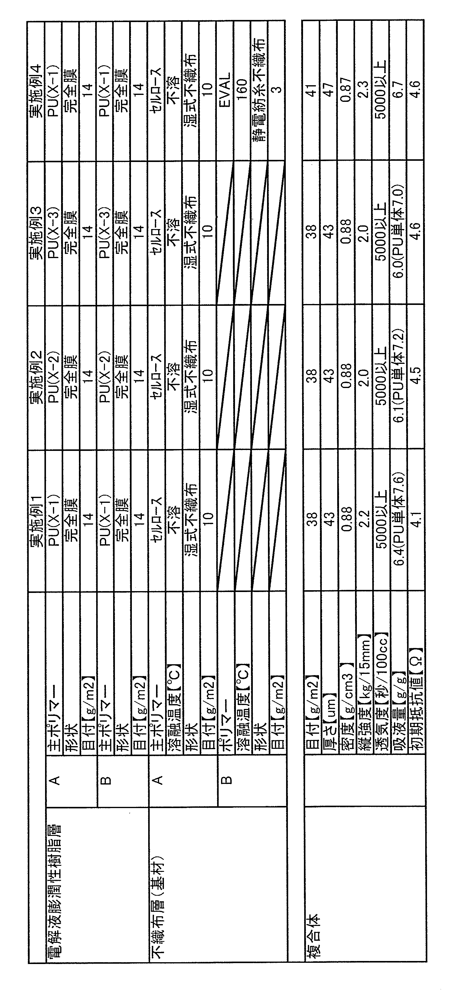
- a slurry was prepared. The slurry was made with a round paper machine and dried at a dryer temperature of 130 ° C. to prepare a heat-resistant polymer layer having a basis weight of 10.9 g / m 2 and a thickness of 15 ⁇ m.
- a battery separator was produced by the following method.
- a resin solution 1 was prepared according to the following formulation, applied onto the entire surface of a release paper using a knife coater, dried at 100 ° C., and then an electrolyte swellable resin film 1 having a thickness of 14 ⁇ m was formed.
- Resin solution 1 Urethane resin composition (X-1) 100 parts by weight Dimethylformamide 15 parts by weight Methyl ethyl ketone 15 parts by weight
- a resin solution 2 is prepared, applied onto the entire surface of the electrolyte swellable resin film 1 formed on the release paper using a knife coater, dried at 100 ° C., and then an electrolyte swellable resin having a thickness of 14 ⁇ m. Film 2 was formed.
- Resin solution 2 Urethane resin composition (X-1) 100 parts by mass Isopropyl alcohol 20 parts by mass Toluene 20 parts by mass
- Example 2 A non-volatile content of 30 in the same manner as in Example 1 except that 150 parts by mass of polyoxypropylene glycol (number average molecular weight 1500) is used instead of 150 parts by mass of polyoxyethylene glycol (number average molecular weight 1500).
- a mass% urethane resin composition (X-2) was obtained.
- a separator was produced in the same manner as in Example 1 except that this urethane resin composition (X-2) was used instead of the urethane resin composition (X-1) in Example 1. The performance of the obtained separator is shown in Table 1.
- Example 3 The same method as in Example 1 except that 150 parts by mass of a copolymer of ethylene oxide and tetrahydrofuran (number average molecular weight 1500) is used instead of 150 parts by mass of the polyoxyethylene glycol (number average molecular weight 1500).
- a urethane resin composition (X-3) having a nonvolatile content of 30% by mass was obtained by boiling.
- a separator was produced in the same manner as in Example 1 except that this urethane resin composition (X-3) was used in place of the urethane resin composition (X-1) in Example 1. The performance of the obtained separator is shown in Table 1.
- Example 4 After (3) processing in Example 1, the following treatment was performed as (4).
- (4) Formation of Low Melting Point Polymer Layer First, an ethylene-vinyl alcohol copolymer (manufactured by Kuraray Co., Ltd .: EVAL-G) having a melting point of 160 ° C. was added to a DMSO solvent so as to be 14% by mass, The solution was placed and dissolved to obtain a spinning dope. Electrospinning was performed with a spinning device using the obtained spinning solution. In the spinning device, a needle having an inner diameter of 0.9 mm was used as the die, and the distance between the die and the formed sheet take-up device was 8 cm. Moreover, the sheet
- EVAL-G ethylene-vinyl alcohol copolymer having a melting point of 160 ° C.
- the conveyor speed is 0.1 m / min
- the stock solution is extruded from the base at a predetermined supply rate
- a 20 kV applied voltage is applied to the base
- nanofibers having an average fiber diameter of 200 nm are 3.2 g / m 2 on the heat-resistant polymer layer. It was laminated to become.
- the composite thus obtained was further subjected to a heat press treatment at 130 ° C., and the heat-resistant polymer layer and the low melting point polymer layer were integrated.
- the performance of the obtained separator is shown in Table 1.
- Comparative Example 1 (1) Preparation of urethane resin composition Instead of 150 parts by mass of the polyoxyethylene glycol (number average molecular weight 1500), a polyester polyol (number average molecular weight 1500) obtained by reacting adipic acid and 1,4-butanediol.
- the comparative urethane resin composition (X′-1) having a nonvolatile content of 30% by mass was obtained in the same manner as in Example 1, except that 150 parts by mass of (A) was used.
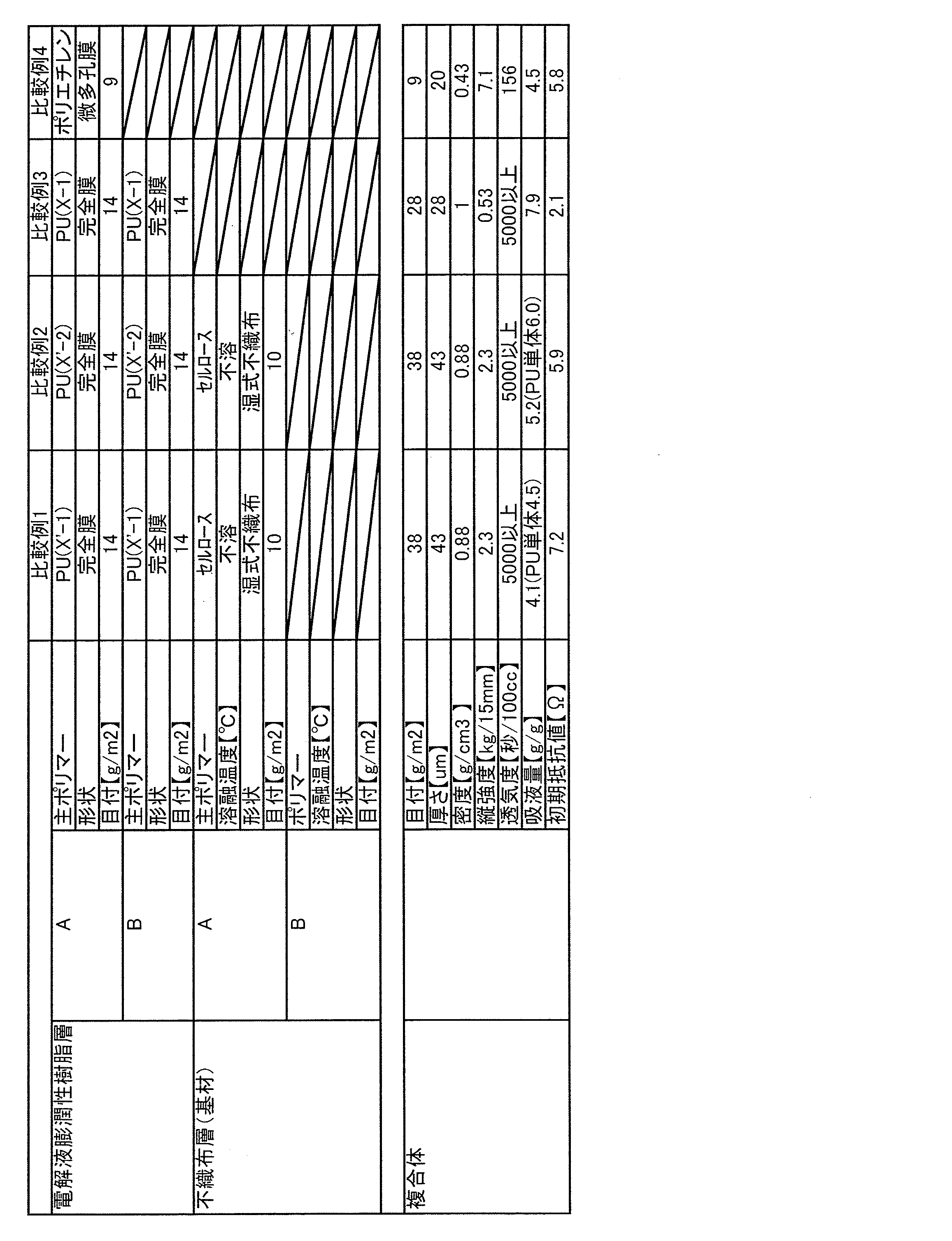
- a separator was produced in the same manner as in Example 1 except that this urethane resin composition (X′-1) was used in place of the urethane resin composition (X-1) in Example 1. The performance of the obtained separator is shown in Table 2.
- the reaction is terminated by adding 3 parts by mass of methanol, and 175 parts by mass of methyl ethyl ketone is added as a diluent solvent, so that a nonvolatile resin containing urethane resin is contained.
- a comparative urethane resin composition (X′-2) having a content of 30% by mass was obtained.
- a separator was produced in the same manner as in Example 1 except that this urethane resin composition (X′-2) was used in place of the urethane resin composition (X-1) in Example 1.
- the performance of the obtained separator is shown in Table 2.
- Example 3 It produced similarly to Example 1 except omitting the base material layer (2) which consists of a nonwoven fabric.
- the performance of the obtained separator is shown in Table 2.
- Comparative Example 4 100 parts by mass of polyethylene (Mitsui Chemicals Co., Ltd .: 5202B) is supplied to the twin screw extruder, and 120 parts by mass of liquid paraffin is injected from the injection port provided in the cylinder of the twin screw extruder and melted sufficiently at 220 ° C. A polyethylene solution was prepared by kneading, and the polyethylene solution was extruded into a sheet form from a T-die attached to the tip of the twin-screw extruder and cooled.
- polyethylene Mitsubishi Chemicals Co., Ltd .: 5202B
- This sheet was set in a biaxial stretching machine, and simultaneously biaxially stretched 7 ⁇ 7 times at 115 ° C., and liquid paraffin was extracted with methyl ethyl ketone to obtain a polyethylene microporous film.
- the performance of the obtained microporous film is shown in Table 2.
- the separators of Examples 1 to 4 each have a low initial resistance due to the high swellability of the urethane resin with respect to the electrolyte, and exhibit excellent properties as a high-power non-aqueous battery separator. Furthermore, in these examples, the strength of the separator is high, and the handleability during manufacture is excellent. Furthermore, the resistance to hydrogen fluoride is high, and the weight of the separator does not change at all against hydrogen fluoride (HF) generated by the decomposition of the electrolytic solution.
- HF hydrogen fluoride
- Example 4 since the low melting point polymer can be melted by abnormal heat generation to form a film, the resistance value after heating becomes 8.2 times the resistance value before heating, and good shutdown characteristics are obtained. It also shows.
- the separator of Comparative Example 2 has ionic conductivity, it cannot be used as a separator for non-aqueous batteries because mechanical stability is lowered.
- the separator of Comparative Example 3 has a low strength and is likely to be damaged. Therefore, the separator is poor in workability and cannot be used as a separator for non-aqueous batteries.
- the microporous film of Comparative Example 4 Since the microporous film of Comparative Example 4 has a high initial resistance, the internal resistance of the battery becomes high when used as a separator for a non-aqueous battery, and not only a high output cannot be obtained, but also there is a shutdown characteristic due to melting. Since the sheet form is not maintained when the heat generation proceeds and the temperature becomes higher, the pole materials may come into contact with each other to further increase the danger, which is insufficient as a safety function.
- the separator for non-aqueous batteries of the present invention can be usefully used for non-aqueous batteries.
Landscapes
- Chemical & Material Sciences (AREA)
- Chemical Kinetics & Catalysis (AREA)
- Electrochemistry (AREA)
- General Chemical & Material Sciences (AREA)
- Engineering & Computer Science (AREA)
- Manufacturing & Machinery (AREA)
- Health & Medical Sciences (AREA)
- Medicinal Chemistry (AREA)
- Polymers & Plastics (AREA)
- Organic Chemistry (AREA)
- Cell Separators (AREA)
Abstract
Description
この発明では、電極と電解質の密着性を良好にして、電解質溶液なみの界面インピーダンスを得ることが可能なリチウム二次電池を提供することができる。
この文献では、加工性に優れ、ある一定レベルの電解液膨潤性を得ることが出来、さらに電解物質の脱落・移動に伴う内部短絡を防止できる非水系電池を得ることができる。
また、特許文献1及び2とも電池の温度上昇に際し、電気抵抗の増大により電池反応を遮断するような安全装置も付与されていない。
本発明の別の目的は、低抵抗化と耐短絡性の双方を実現できる非水系電池用セパレータを提供することにある。
本発明のさらに別の目的は、速やかに溶融膜を形成してシャットダウン特性を発揮できるだけでなく、耐電解液性をも有する非水系電池用セパレータを提供することにある。
本発明のさらに他の目的は、高出力であるとともに安全性にも優れている非水系電池を提供することにある。
ポリエーテルポリオール(a2)とを含有するポリオール(A)と、
ポリイソシアネート(B)とを反応させて得られるウレタン樹脂(C)よりなる電解液膨潤性樹脂層が、繊維集合体よりなる基材層の少なくとも片面に形成され、両者が一体化していることを特徴とする非水系電池用セパレータである。
片末端に2個の水酸基を有するビニル重合体(a1’)を主鎖とし、その側鎖に数平均分子量200~800のポリオキシエチレン鎖を、ビニル重合体(a1)の全量に対して70質量%~98質量%有する数平均分子量2000~7000のビニル重合体(a1)と、ポリエーテルポリオール(a2)とを含有するポリオール(A)、及び、ポリイソシアネート(B)を反応させて得られるウレタン樹脂(C)からシートまたはフィルムを作製する工程と、前記シートまたはフィルムを繊維集合体よりなる支持基材の少なくとも片面に対して貼りあわせる工程と、を含んでいる。
片末端に2個の水酸基を有するビニル重合体(a1’)を主鎖とし、その側鎖に数平均分子量200~800のポリオキシエチレン鎖を、ビニル重合体(a1)の全量に対して70質量%~98質量%有する数平均分子量2000~7000のビニル重合体(a1)と、ポリエーテルポリオール(a2)とを含有するポリオール(A)、及び、ポリイソシアネート(B)を反応させて得られるウレタン樹脂(C)の溶液または分散液を作製する工程と、前記溶液または分散液を繊維集合体よりなる支持基材に対して塗布または含浸する工程と、を含んでいる。
さらに、ウレタン系樹脂が実質的に無孔のフィルムで形成される場合、電解質の離脱などによって生じる短絡を防止することが可能である。
好ましくは、前記電解液膨潤性樹脂層は、実質的に無孔のフィルムで完全膜状に形成されていてもよく、前記基材層は、耐熱性ポリマーよりなる繊維状物と、さらに必要に応じて低融点ポリマーの繊維状物との積層体で形成されていてもよい。
電解液膨潤性樹脂層は、電解液膨潤性樹脂から形成され、前記電解液膨潤性樹脂としては、片末端に2個の水酸基を有するビニル重合体(a1’)を主鎖とし、その側鎖に数平均分子量200~800のポリオキシエチレン鎖を、ビニル重合体(a1)の全量に対して70質量%~98質量%有する数平均分子量2000~7000のビニル重合体(a1)と、ポリエーテルポリオール(a2)とを含有するポリオール(A)、及び、ポリイソシアネート(B)を反応させて得られるウレタン樹脂(C)を使用することができる。
前記2個の水酸基とメルカプト基等を有する連鎖移動剤(D)としては、例えば3-メルカプト-1,2-プロパンジオール(チオグリセリン)、1-メルカプト-1,1-メタンジオール、1-メルカプト-1,1-エタンジオール、2-メルカプト-1,3-プロパンジオール等を使用することができる。なかでも3-メルカプト-1,2-プロパンジオールを使用するのが、臭気が少なく作業性や安全性の点で優れ、かつ汎用であるため好ましい。
繊維集合体よりなる基材層は、耐電解液性を有しているとともに、電解液膨潤性樹脂層と一体化することができる限り特に限定されず、各種繊維材料を用いて形成される織編物、不織布などのいずれであってもよいが、好ましくは、基材層は不織布である。
耐熱性ポリマー層は、電解液膨潤性樹脂層の支持体として、および必要に応じて設けてもよい低融点ポリマー層が皮膜を形成する際の支持体として機能する。高温に曝された場合であっても、セパレータ全体の形状を保持できる観点から、耐熱性ポリマー層は、融点が200℃を超える高融点ポリマーおよび熱不融性ポリマーからなる群から選択された少なくとも一種の耐熱性ポリマーを含むことが好ましい。
また、必要により積層させる低融点ポリマーと高融点ポリマーとの融点の差は、例えば、50~200℃程度、好ましくは60~180℃程度であってもよい。
基材層は、前述した耐熱性ポリマー層と融点が100~200℃の低融点ポリマーからなる低融点ポリマー層よりなる不織布であってもよい。この場合、必要により積層する低融点ポリマー層は、融点100~200℃の低融点ポリマーを含むことが重要である。低融点ポリマー層が融点100~200℃のポリマーを含むことにより、異常電流や、リチウムデンドライドによる内部短絡によって電池の温度上昇が生じた場合であっても、低融点ポリマー層が溶融して皮膜を形成して抵抗を高め、シャットダウン特性を与えることができる。
低融点ポリマー層は、シャットダウン特性を達成できる限り、基材層において、電解液膨潤性樹脂層側に形成されてもよいし、電解液膨潤性樹脂層とは相反する側に形成されてもよい。
エチレン-ビニルアルコール共重合体は、エチレン/酢酸ビニル系共重合体の酢酸ビニル部分をケン化することにより得ることができ、ケン化度としては、例えば、約95モル%以上、好ましくは98モル%以上、より好ましくは99モル%以上100モル%以下であってもよい。
本発明のセパレータの製造方法は、繊維集合体よりなる基材層と電解液膨潤性樹脂層とが一体化している限り特に限定されず、様々な方法が考えられる。例えば、製造方法の一実施態様としては、前記ウレタン樹脂(C)から作製されたシートまたはフィルムを、繊維集合体よりなる支持基材の少なくとも片面に対して貼りあわせて積層する工程を少なくとも含んでいればよい。この場合、前記シートまたはフィルムは、通常、後述する方法により、ウレタン樹脂(C)から形成される。また、他の実施態様としては、繊維集合体よりなる支持基材に対して、前記ウレタン樹脂(C)を含む溶液または分散液を含浸または塗布する工程を含んでいてもよい。
静電紡糸の方法としては特に制限はなく、紡糸原液を供給できる導電性部材に高電圧を印加することで、接地した対極側にナノファイバーを堆積させる方法をとる。これにより、原液供給部から吐出された紡糸原液が帯電分裂され、ついで電場により液滴の一点からファイバーが連続的に引き出され、分割された繊維が多数拡散する。ポリマーの濃度が10%以下であっても、溶媒は繊維形成と細化の段階で乾燥しやすく、原液供給部より数cm~数十cm離れた設置された捕集ベルトあるいはシートに堆積する。堆積と共に半乾燥繊維は微膠着し、繊維間の移動を防止し、新たな微細繊維が逐次堆積し、緻密なシート状のナノファイバー層が得られる。
このようにして得られた電池用セパレータは、総目付が、例えば5~45g/m2程度、好ましくは6~25g/m2程度、さらに好ましくは7~20g/m2程度の範囲であってもよい。
本発明は、前記セパレータを用いた非水系電池も包含する。非水系電池の基本的な構造は、正極と、負極と、非水電解液と、セパレータとを備え、その他、必要に応じて非水電解液電池の技術分野で通常使用されている他の部材を備える。本発明の非水系電池は、その形状には特に制限されず、コイン型、ボタン型、ペーパー型、円筒型、角型等、種々の形状の電池として使用できる。
基材層において、顕微鏡により倍率5000倍で撮影した不織布構成繊維の断面の拡大写真から、無作為に100本の繊維を選び、それらの繊維径を測定し、その平均値を平均繊維径とした。
試料50mgを示差走査熱量計(セイコーインスツル(株)製:DSC6200)により測定し吸熱ピーク値を融点とした。
JIS P 8124「紙のメートル坪量測定方法」に準じて測定した。
JIS P 8118「紙及び板紙の厚さと密度の試験方法」に準じて測定した。
JIS P 8113「紙及び板紙の引張特性の試験方法」に準じて測定した。
50mm×50mmの試料を1mol%の4フッ化ホウ酸リチウム液(キシダ化学(株):1mol/L LiBF4/EC:EMC (3:7)v/v%)(23℃)に浴比1/100の条件で30分浸漬し、30秒間自然液切りした後の試料重量を測定し、保液された液体の重量を浸漬前の試料重量で除することによって吸液量を算出した。
JIS P 8117に準じガーレ式透気度試験器を用いて測定した。
予め秤量した試料サンプル(5×5cm)に対して、1mol%の6フッ化リン酸リチウム液(キシダ化学(株);1mol/L LiPF6/EC:EMC(3:7)v/v%)を加え、100℃で30分放置した後、試料サンプルを取り出し、水洗、乾燥した試料サンプルの重量を測定し、6フッ化リン酸リチウム液へ浸漬する前後の試料サンプルの重量減少率(%)を求めた。
試料を、1mol%の4フッ化ホウ酸リチウム液(キシダ化学(株):1mol/L LiBF4/EC:EMC (3:7)v/v%)に20℃、30分浸漬し、保液十分な状態(30秒液切りした状態)で、測定雰囲気(20℃×65%RH)にてインピーダンス測定器(国洋電気工業(株)製:KC-547 LCR METER)で測定した。
抵抗値が5Ω以下の試料ならば低抵抗となり、高出力の非水系電池が作製可能なことから○と判定した。それ以上は抵抗が高すぎ、非水系電池として劣ったものとなってしまうため×と判定した。
ステンレス製密閉容器内に電解液1mol%の6フッ化リン酸リチウム液(キシダ化学(株):1mol/L LiPF6/EC:EMC (3:7)v/v%)と試料を投入し、オイルバス中で、[(低融点ポリマー層を構成する低融点ポリマーの融点+10)]℃で30分加熱し、加熱後の試料を、保液十分な状態(30秒液切りした状態)で、測定雰囲気(20℃×65%RH)にてインピーダンス測定器(国洋電気工業(株)製:KC-547 LCR METER)で測定した。
加熱前の抵抗値に対し、抵抗値が2倍以上に向上しているサンプルをシャットダウン特性が発現している○と判定し、それ以下を×とした。
(1)ウレタン樹脂組成物の調製
温度計、撹拌装置、還流冷却管、及び窒素導入管を備えた4ツ口フラスコに、メチルエチルケトン500質量部を仕込み、次いで前記反応容器中にポリオキシエチレンモノメチルエーテルメタクリレート(ポリオキシエチレン鎖の数平均分子量500)485質量部と3-メルカプト-1,2-プロパンジオール15質量部を供給し、反応させることによって、ビニル重合体の全量に対するポリオキシエチレン鎖の割合が95質量%である数平均分子量6000で片末端に2個の水酸基を有するビニル重合体(a1-1)を得た。
1.7dtex、長さ3mmの溶剤紡糸セルロース繊維(コートールズ社製、テンセル)をパルパーとファイバライザーにて叩解し、CSF100mlのフィブリル化物とした。この繊維を主体繊維とし、ポリビニルアルコール系繊維((株)クラレ製、「VPB105-2」)をバインダー繊維として、主体繊維:バインダー繊維の重量比が80:20となるような量で添加してスラリーを調製した。
このスラリーを丸網抄紙機にて抄紙し、ドライヤー温度130℃で乾燥を行い、坪量10.9g/m2、厚さ15μmの耐熱性ポリマー層を作製した。
下記の処方で樹脂溶液1を調製し、ナイフコータを用い離型紙上に全面塗布し、100℃で乾燥させた後、厚さ14μmの電解液膨潤性樹脂フィルム1を形成した。
ウレタン樹脂組成物(X-1) 100質量部
ジメチルホルムアミド 15質量部
メチルエチルケトン 15質量部
ウレタン樹脂組成物(X-1) 100質量部
イソプロピルアルコール 20質量部
トルエン 20質量部
前記ポリオキシエチレングリコール(数平均分子量1500)150質量部の代わりに、ポリオキシプロビレングリコール(数平均分子量1500)を150質量部使用すること以外は、実施例1と同様の方法で不揮発分30質量%のウレタン樹脂組成物(X-2)を得た。実施例1のウレタン樹脂組成物(X-1)に代えて、このウレタン樹脂組成物(X-2)を用いる以外は、実施例1と同様にセパレータを作製した。得られたセパレータの性能を表1に示す。
前記ポリオキシエチレングリコール(数平均分子量1500)150質量部の代わりに、エチレンオキサイドとテトラヒドロフランとの共重合体(数平均分子量1500)を150質量部使用すること以外は、実施例1と同様の方怯で不揮発分30質量%のウレタン樹脂組成物(X-3)を得た。実施例1のウレタン樹脂組成物(X-1)に代えて、このウレタン樹脂組成物(X-3)を用いる以外は、実施例1と同様にセパレータを作製した。得られたセパレータの性能を表1に示す。
実施例1の(3)加工以後に(4)として以下の処理を行った。
(4)低融点ポリマー層の形成
まず融点160℃のエチレン-ビニルアルコール共重合体((株)クラレ製:EVAL-G)を14質量%となるようにDMSO溶媒に投入後、25℃で静置溶解し、紡糸原液を得た。得られた紡糸原液を用い、紡糸装置にて静電紡糸を行った。
紡糸装置では、口金として内径が0.9mmのニードルを使用し、口金と形成シート引取り装置との間の距離は8cmとした。また、形成シート引取り装置に前記(3)で得られたシートを巻き付けた。次いでコンベア速度0.1m/分、原液を所定の供給量で口金から押し出し、口金に20kV印加電圧を与えて、耐熱性ポリマー層上に平均繊維径が200nmのナノファイバーを3.2g/m2になるよう積層させた。
(1)ウレタン樹脂組成物の調製
前記ポリオキシエチレングリコール(数平均分子量1500)150質量部の代わりに、アジピン酸と1,4-ブタンジオールとを反応させて得られるポリエステルポリオール(数平均分子量1500)を150質量部使用すること以外は、実施例1と同様の方法で不揮発分30質量%の比較用ウレタン樹脂組成物(X’-1)を得た。実施例1のウレタン樹脂組成物(X-1)に代えて、このウレタン樹脂組成物(X’-1)を用いる以外は、実施例1と同様にセパレータを作製した。得られたセパレータの性能を表2に示す。
温度計、撹拌装置、還流冷却管、及び窒素導入管を備えた4ツ口フラスコに、メチルエチルケトン450質量部を仕込み、次いで前記反応容器中にポリオキシエチレンモノメチルエーテルメタクリレート(ポリオキシエチレン鎖の数平均分子量1000)400質量部と3-メルカプト-1,2-プロパンジオール7質量部を供給し、反応させることによって、ビニル重合体の全量に対するポリオキシエチレン鎖の割合が95質量%である数平均分子量7000で片末端に2個の水酸基を有するビニル重合体(Y-1)を得た。
不織布よりなる基材層(2)を省略すること以外は実施例1と同様に作製した。得られたセパレータの性能を表2に示す。
二軸押出機にポリエチレン(三井化学(株)製:5202B)100質量部を供給し、流動パラフィン120質量部を二軸押出機のシリンダーに設けた注入口から注入して220℃で十分に溶融混練を行うことによりポリエチレン溶液を調製し、二軸押出機の先端に取り付けたTダイからポリエチレン溶液をシート状に押し出し冷却した。このシートを二軸延伸機にセットし、115℃で7×7倍に同時二軸延伸を行い、メチルエチルケトンで流動パラフィンを抽出してポリエチレン微多孔フィルムを得た。得られた微多孔フィルムの性能を表2に示す。
Claims (13)
- 片末端に2個の水酸基を有するビニル重合体(a1’)を主鎖とし、その側鎖に数平均分子量200~800のポリオキシエチレン鎖を、ビニル重合体(a1)の全量に対して70質量%~98質量%有する数平均分子量2000~7000のビニル重合体(a1)と、
ポリエーテルポリオール(a2)とを含有するポリオール(A)と、
ポリイソシアネート(B)とを反応させて得られるウレタン樹脂(C)よりなる電解液膨潤性樹脂層が、繊維集合体よりなる基材層の少なくとも片面に形成され、両者が一体化していることを特徴とする非水系電池用セパレータ。 - 請求項1記載のセパレータにおいて、前記ビニル重合体(a1)が、2個の水酸基と1個のメルカプト基とを有する連鎖移動剤(D)、及び、数平均分子量200~800のポリオキシエチレン鎖を有するビニル単量体(e)を含むビニル単量体(E)を反応させて得られるものである非水系電池用セパレータ。
- 請求項1または2記載のセパレータにおいて、電解液膨潤性樹脂層が、実質的に無孔である非水系電池用セパレータ。
- 請求項1から3のいずれか一項のセパレータにおいて、基材層が、少なくとも耐熱性ポリマー層を含んでおり、前記耐熱性ポリマーは、融点が200℃を超える高融点ポリマーもしくは熱不融性ポリマーで構成される非水系電池用セパレータ。
- 請求項1から4のいずれか一項のセパレータにおいて、基材層を構成する耐熱性ポリマーが、全芳香族ポリアミド系ポリマー、ポリビニルアルコール系ポリマー、及びセルロース系ポリマーからなる群から選択された少なくとも一種で構成されている非水系電池用セパレータ。
- 請求項1から5のいずれか一項のセパレータにおいて、基材層が、不織布で構成される非水系電池用セパレータ。
- 請求項6のセパレータにおいて、不織布が、湿式不織布、乾式不織布、メルトブローン不織布、スパンボンド不織布、および静電紡糸不織布からなる群より選択された1種または2種以上の不織布または不織布積層体である非水系電池用セパレータ。
- 請求項1から7のいずれか一項のセパレータにおいて、基材層が、耐熱性ポリマー層と、融点が100~200℃の低融点ポリマーからなる低融点ポリマー層との積層体よりなる非水系電池用セパレータ。
- 請求項8のセパレータにおいて、低融点ポリマー層が、平均繊維径1000nm以下のナノファイバーを含む不織布である非水系電池用セパレータ。
- 請求項8または9のセパレータにおいて、低融点ポリマー層を形成する低融点ポリマーが、ポリオレフィン系ポリマー、エチレン-ビニルアルコール系共重合物、及びフッ素系ポリマーからなる群から選択される少なくとも一種で構成される非水系電池用セパレータ。
- 片末端に2個の水酸基を有するビニル重合体(a1’)を主鎖とし、その側鎖に数平均分子量200~800のポリオキシエチレン鎖を、ビニル重合体(a1)の全量に対して70質量%~98質量%有する数平均分子量2000~7000のビニル重合体(a1)と、ポリエーテルポリオール(a2)とを含有するポリオール(A)、及び、ポリイソシアネート(B)を反応させて得られるウレタン樹脂(C)からシートまたはフィルムを作製する工程と、
前記シートまたはフィルムを繊維集合体よりなる支持基材の少なくとも片面に対して貼りあわせる工程と、
を含む非水系電池用セパレータの製造方法。 - 片末端に2個の水酸基を有するビニル重合体(a1’)を主鎖とし、その側鎖に数平均分子量200~800のポリオキシエチレン鎖を、ビニル重合体(a1)の全量に対して70質量%~98質量%有する数平均分子量2000~7000のビニル重合体(a1)と、ポリエーテルポリオール(a2)とを含有するポリオール(A)、及び、ポリイソシアネート(B)を反応させて得られるウレタン樹脂(C)の溶液または分散液を作製する工程と、
前記溶液または分散液を、繊維集合体よりなる支持基材に対して塗布または含浸する工程と、
を含む非水系電池用セパレータの製造方法。 - 請求項1から10のいずれか一項に記載の非水系電池用セパレータを使用した非水系電池。
Priority Applications (5)
| Application Number | Priority Date | Filing Date | Title |
|---|---|---|---|
| CN201180051499.3A CN103190016B (zh) | 2010-10-27 | 2011-10-13 | 非水类电池用隔膜和使用其的非水类电池以及非水类电池用隔膜的制造方法 |
| EP11836029.6A EP2634838B1 (en) | 2010-10-27 | 2011-10-13 | Separator for non-aqueous batteries and non-aqueous battery equipped with same, and process for manufacturing separator for non-aqueous batteries |
| JP2012540764A JP5771621B2 (ja) | 2010-10-27 | 2011-10-13 | 非水系電池用セパレータ及びそれを用いた非水系電池、ならびに非水系電池用セパレータの製造方法 |
| KR1020137013537A KR101929063B1 (ko) | 2010-10-27 | 2011-10-13 | 비수계 전지용 세퍼레이터 및 그것을 사용한 비수계 전지, 그리고 비수계 전지용 세퍼레이터의 제조 방법 |
| US13/881,747 US9343721B2 (en) | 2010-10-27 | 2011-10-13 | Separator for non-aqueous batteries and non-aqueous battery equipped with same, and process for manufacturing separator for non-aqueous batteries |
Applications Claiming Priority (2)
| Application Number | Priority Date | Filing Date | Title |
|---|---|---|---|
| JP2010-240329 | 2010-10-27 | ||
| JP2010240329 | 2010-10-27 |
Publications (1)
| Publication Number | Publication Date |
|---|---|
| WO2012056890A1 true WO2012056890A1 (ja) | 2012-05-03 |
Family
ID=45993615
Family Applications (1)
| Application Number | Title | Priority Date | Filing Date |
|---|---|---|---|
| PCT/JP2011/073502 Ceased WO2012056890A1 (ja) | 2010-10-27 | 2011-10-13 | 非水系電池用セパレータ及びそれを用いた非水系電池、ならびに非水系電池用セパレータの製造方法 |
Country Status (6)
| Country | Link |
|---|---|
| US (1) | US9343721B2 (ja) |
| EP (1) | EP2634838B1 (ja) |
| JP (1) | JP5771621B2 (ja) |
| KR (1) | KR101929063B1 (ja) |
| CN (1) | CN103190016B (ja) |
| WO (1) | WO2012056890A1 (ja) |
Cited By (4)
| Publication number | Priority date | Publication date | Assignee | Title |
|---|---|---|---|---|
| JP2016013660A (ja) * | 2014-07-02 | 2016-01-28 | 旭化成イーマテリアルズ株式会社 | 積層微多孔性フィルム及びリチウムイオン二次電池用セパレータ |
| JP2019512838A (ja) * | 2016-03-29 | 2019-05-16 | ディーケイジェイ・ニュー・エナジー・エス・アンド・ティー・カンパニー・リミテッド | 非多孔質セパレータ及びその使用 |
| JPWO2022145318A1 (ja) * | 2020-12-28 | 2022-07-07 | ||
| KR20250105371A (ko) | 2022-10-31 | 2025-07-08 | 니폰 제온 가부시키가이샤 | 전기 화학 소자 기능층용 조성물, 전기 화학 소자 기능층용 조성물 전구체, 전기 화학 소자용 기능층, 전기 화학 소자용 적층체, 및 전기 화학 소자 |
Families Citing this family (15)
| Publication number | Priority date | Publication date | Assignee | Title |
|---|---|---|---|---|
| US8641273B2 (en) * | 2010-11-02 | 2014-02-04 | Sinoelectric Powertrain Corporation | Thermal interlock for battery pack, device, system and method |
| KR101256968B1 (ko) * | 2012-10-25 | 2013-04-30 | 톱텍에이치앤에스 주식회사 | 이차전지 분리막용 pet 부직포 및 이를 포함하는 이차전지용 분리막 |
| CN103855351A (zh) * | 2014-03-11 | 2014-06-11 | 东莞新能源科技有限公司 | 锂离子电池、所使用的隔离膜及隔离膜的制备方法 |
| KR102221807B1 (ko) * | 2014-08-11 | 2021-03-02 | 삼성에스디아이 주식회사 | 이차 전지 |
| US10312527B2 (en) | 2014-11-10 | 2019-06-04 | Lanxess Solutions Us Inc. | Energy storage device comprising a polyurethane separator |
| US10186716B2 (en) | 2014-11-10 | 2019-01-22 | Lanxess Solutions Us Inc. | Non-aqueous flow cell comprising a polyurethane separator |
| EP3082186B1 (en) | 2015-04-14 | 2019-07-24 | Lanxess Solutions US Inc. | Non-aqueous flow cell comprising a polyurethane separator |
| US10573926B1 (en) | 2016-03-23 | 2020-02-25 | American Lithium Energy Corporation | Hybrid solid-state electrolyte |
| US10454142B2 (en) * | 2016-05-31 | 2019-10-22 | American Lithium Energy Corporation | Enhanced solid state battery cell |
| CN106654127A (zh) * | 2016-12-23 | 2017-05-10 | 合肥星源新能源材料有限公司 | 一种高浸润性的锂离子电池隔膜及其制备方法 |
| EP3627586B1 (en) * | 2017-05-17 | 2022-09-28 | Teijin Limited | Separator for non-aqueous secondary batteries, non-aqueous secondary battery, and method for producing non-aqueous secondary battery |
| US10629861B2 (en) * | 2017-05-23 | 2020-04-21 | Samsung Electronics Co., Ltd. | Stretchable battery and method of manufacturing the same |
| KR102501467B1 (ko) * | 2017-11-16 | 2023-02-20 | 삼성전자주식회사 | 복합분리막, 그 제조방법 및 이를 포함하는 이차전지 |
| CN113140871B (zh) * | 2021-03-26 | 2022-11-04 | 西安理工大学 | 一种锂硫电池用自支撑结构的隔膜及其制备方法 |
| CN121405843B (zh) * | 2025-12-25 | 2026-04-17 | 深圳市鸿星创新材料有限公司 | 一种隔膜用大颗粒胶、隔膜涂层浆料、隔膜及电池 |
Citations (4)
| Publication number | Priority date | Publication date | Assignee | Title |
|---|---|---|---|---|
| JP2004055509A (ja) * | 2001-09-27 | 2004-02-19 | Nisshinbo Ind Inc | 非水電解質二次電池、ならびに該二次電池を用いた電源、携帯用機器、輸送または移動用機械、および家庭用電気機器 |
| JP2006019191A (ja) * | 2004-07-02 | 2006-01-19 | Japan Vilene Co Ltd | リチウムイオン二次電池用セパレータ及びリチウムイオン二次電池 |
| JP2009224100A (ja) * | 2008-03-14 | 2009-10-01 | Toray Ind Inc | 電池用セパレーター |
| JP2011046761A (ja) * | 2009-08-25 | 2011-03-10 | Mitsubishi Paper Mills Ltd | 多孔質シート、多孔質シートの製造方法および多孔質シートからなる電気化学素子用セパレータ |
Family Cites Families (8)
| Publication number | Priority date | Publication date | Assignee | Title |
|---|---|---|---|---|
| JPH05226002A (ja) | 1991-02-25 | 1993-09-03 | Honda Motor Co Ltd | リチウム二次電池用ゲル状電解質 |
| JP2001351434A (ja) * | 2000-06-07 | 2001-12-21 | Toyo Tire & Rubber Co Ltd | ゲル状電解質形成組成物、ゲル状電解質及びその製造方法 |
| JP2003003078A (ja) * | 2000-09-19 | 2003-01-08 | Nisshinbo Ind Inc | イオン導電性組成物、ゲル電解質、及び非水電解質電池並びに電気二重層キャパシタ |
| TW579613B (en) | 2001-09-27 | 2004-03-11 | Nisshin Spinning | Nonaqueous electrolyte secondary cell, power supply comprising the secondary cell, portable device, transportable or movable machine, electric apparatus for home use, and method for charging nonaqueous electrolyte secondary cell |
| JP2004031084A (ja) | 2002-06-25 | 2004-01-29 | Oji Paper Co Ltd | リチウムイオン二次電池用セパレータおよびそれを用いた電池 |
| TW200504108A (en) * | 2003-07-24 | 2005-02-01 | Asahi Glass Co Ltd | Polyurethane resins and process for production thereof |
| JP5031606B2 (ja) | 2008-01-30 | 2012-09-19 | ソニー株式会社 | 電池パック及びその製造方法 |
| JP5337550B2 (ja) * | 2008-03-31 | 2013-11-06 | 日東電工株式会社 | 電池用セパレータとこれを用いてなる電池 |
-
2011
- 2011-10-13 US US13/881,747 patent/US9343721B2/en active Active
- 2011-10-13 JP JP2012540764A patent/JP5771621B2/ja active Active
- 2011-10-13 EP EP11836029.6A patent/EP2634838B1/en active Active
- 2011-10-13 CN CN201180051499.3A patent/CN103190016B/zh active Active
- 2011-10-13 KR KR1020137013537A patent/KR101929063B1/ko active Active
- 2011-10-13 WO PCT/JP2011/073502 patent/WO2012056890A1/ja not_active Ceased
Patent Citations (4)
| Publication number | Priority date | Publication date | Assignee | Title |
|---|---|---|---|---|
| JP2004055509A (ja) * | 2001-09-27 | 2004-02-19 | Nisshinbo Ind Inc | 非水電解質二次電池、ならびに該二次電池を用いた電源、携帯用機器、輸送または移動用機械、および家庭用電気機器 |
| JP2006019191A (ja) * | 2004-07-02 | 2006-01-19 | Japan Vilene Co Ltd | リチウムイオン二次電池用セパレータ及びリチウムイオン二次電池 |
| JP2009224100A (ja) * | 2008-03-14 | 2009-10-01 | Toray Ind Inc | 電池用セパレーター |
| JP2011046761A (ja) * | 2009-08-25 | 2011-03-10 | Mitsubishi Paper Mills Ltd | 多孔質シート、多孔質シートの製造方法および多孔質シートからなる電気化学素子用セパレータ |
Non-Patent Citations (1)
| Title |
|---|
| See also references of EP2634838A4 * |
Cited By (4)
| Publication number | Priority date | Publication date | Assignee | Title |
|---|---|---|---|---|
| JP2016013660A (ja) * | 2014-07-02 | 2016-01-28 | 旭化成イーマテリアルズ株式会社 | 積層微多孔性フィルム及びリチウムイオン二次電池用セパレータ |
| JP2019512838A (ja) * | 2016-03-29 | 2019-05-16 | ディーケイジェイ・ニュー・エナジー・エス・アンド・ティー・カンパニー・リミテッド | 非多孔質セパレータ及びその使用 |
| JPWO2022145318A1 (ja) * | 2020-12-28 | 2022-07-07 | ||
| KR20250105371A (ko) | 2022-10-31 | 2025-07-08 | 니폰 제온 가부시키가이샤 | 전기 화학 소자 기능층용 조성물, 전기 화학 소자 기능층용 조성물 전구체, 전기 화학 소자용 기능층, 전기 화학 소자용 적층체, 및 전기 화학 소자 |
Also Published As
| Publication number | Publication date |
|---|---|
| EP2634838A4 (en) | 2016-10-05 |
| CN103190016A (zh) | 2013-07-03 |
| CN103190016B (zh) | 2015-05-20 |
| EP2634838B1 (en) | 2017-11-29 |
| US20130224557A1 (en) | 2013-08-29 |
| KR20140037794A (ko) | 2014-03-27 |
| US9343721B2 (en) | 2016-05-17 |
| JP5771621B2 (ja) | 2015-09-02 |
| EP2634838A1 (en) | 2013-09-04 |
| KR101929063B1 (ko) | 2018-12-13 |
| JPWO2012056890A1 (ja) | 2014-03-20 |
Similar Documents
| Publication | Publication Date | Title |
|---|---|---|
| JP5771621B2 (ja) | 非水系電池用セパレータ及びそれを用いた非水系電池、ならびに非水系電池用セパレータの製造方法 | |
| JP5529148B2 (ja) | 非水系電池用セパレータ及びそれを用いた非水系電池、ならびに非水系電池用セパレータの製造方法 | |
| KR102190068B1 (ko) | 폴리올레핀 다공질 막, 이를 이용한 전지용 세퍼레이터 및 이들의 제조 방법 | |
| JP5189459B2 (ja) | リチウム電池用セパレータ及びそれを用いたリチウム電池 | |
| TWI479725B (zh) | 分隔器及含有此分隔器之電化學裝置 | |
| CN104106155B (zh) | 电池用隔膜及电池用隔膜的制备方法 | |
| JP4946006B2 (ja) | 複合多孔質膜及びその製造方法 | |
| JP5031835B2 (ja) | 耐熱性超極細繊維状分離膜及びそれを利用した二次電池 | |
| CN102958694B (zh) | 复合多孔质膜、复合多孔质膜的制造方法及使用了该复合多孔质膜的电池用隔板 | |
| CN104393219A (zh) | 非水系二次电池用隔膜、其制造方法和非水系二次电池 | |
| CN104733675A (zh) | 隔膜的制造方法,由此形成的隔膜以及具有该隔膜的电化学器件的制造方法 | |
| CN101923957A (zh) | 蓄电装置用隔离物 | |
| WO2012029699A1 (ja) | 複合多孔質膜及びその製造方法 | |
| CN103797614B (zh) | 电池用隔膜及电池用隔膜的制备方法 | |
| US20230178851A1 (en) | Separator for electrochemical device and electrochemical device comprising same | |
| KR20150141403A (ko) | 복합 다공성 분리막 및 그 제조방법과 이를 이용한 이차전지 | |
| KR20210132607A (ko) | 비수 전해액 이차 전지용 적층 세퍼레이터의 제조 방법 및 비수 전해액 이차 전지용 적층 세퍼레이터 |
Legal Events
| Date | Code | Title | Description |
|---|---|---|---|
| 121 | Ep: the epo has been informed by wipo that ep was designated in this application |
Ref document number: 11836029 Country of ref document: EP Kind code of ref document: A1 |
|
| ENP | Entry into the national phase |
Ref document number: 2012540764 Country of ref document: JP Kind code of ref document: A |
|
| WWE | Wipo information: entry into national phase |
Ref document number: 13881747 Country of ref document: US |
|
| NENP | Non-entry into the national phase |
Ref country code: DE |
|
| REEP | Request for entry into the european phase |
Ref document number: 2011836029 Country of ref document: EP |
|
| WWE | Wipo information: entry into national phase |
Ref document number: 2011836029 Country of ref document: EP |
|
| ENP | Entry into the national phase |
Ref document number: 20137013537 Country of ref document: KR Kind code of ref document: A |