WO2012060314A1 - Lecteur de disque - Google Patents
Lecteur de disque Download PDFInfo
- Publication number
- WO2012060314A1 WO2012060314A1 PCT/JP2011/075037 JP2011075037W WO2012060314A1 WO 2012060314 A1 WO2012060314 A1 WO 2012060314A1 JP 2011075037 W JP2011075037 W JP 2011075037W WO 2012060314 A1 WO2012060314 A1 WO 2012060314A1
- Authority
- WO
- WIPO (PCT)
- Prior art keywords
- flap
- plate
- disk
- main body
- edge
- Prior art date
- Legal status (The legal status is an assumption and is not a legal conclusion. Google has not performed a legal analysis and makes no representation as to the accuracy of the status listed.)
- Ceased
Links
Images

Classifications
-
- G—PHYSICS
- G11—INFORMATION STORAGE
- G11B—INFORMATION STORAGE BASED ON RELATIVE MOVEMENT BETWEEN RECORD CARRIER AND TRANSDUCER
- G11B17/00—Guiding record carriers not specifically of filamentary or web form, or of supports therefor
- G11B17/02—Details
- G11B17/04—Feeding or guiding single record carrier to or from transducer unit
- G11B17/05—Feeding or guiding single record carrier to or from transducer unit specially adapted for discs not contained within cartridges
- G11B17/051—Direct insertion, i.e. without external loading means
-
- G—PHYSICS
- G11—INFORMATION STORAGE
- G11B—INFORMATION STORAGE BASED ON RELATIVE MOVEMENT BETWEEN RECORD CARRIER AND TRANSDUCER
- G11B17/00—Guiding record carriers not specifically of filamentary or web form, or of supports therefor
- G11B17/02—Details
- G11B17/04—Feeding or guiding single record carrier to or from transducer unit
- G11B17/0401—Details
- G11B17/0402—Servo control
- G11B17/0404—Servo control with parallel drive rollers
Definitions
- the present invention relates to a disk device, and more particularly to the attachment of a flap holding spring.
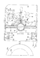
- FIGS. This is a Blu-ray Disc type recorder (or player) equipped with a disk slot loading mechanism. 4 and 5 show the unloading state. FIG. 6 shows the loading state. 7 and 8 show the main part.
- the loader chassis 1 includes a chassis main body 1A and a lid plate 1B covering the chassis main body 1A.
- a disk insertion slot 2 for slotting in a small disk Da having a diameter of 8 cm and a large disk Db having a diameter of 12 cm in the direction of arrow a and slotting out in the direction of arrow b.
- a traverse chassis 6 on which a spindle motor 4 with a turntable 3 and an optical pickup 5 movable along the radial direction of the disks Da and Db are mounted.
- the rear portion of the traverse chassis 6 is pivotally supported by the loader chassis 1 via a support shaft 7 so as to be rotatable in the directions of arrows c and d.
- a cam slider 8 is slidably disposed in the left and right directions e and f perpendicular to the directions of arrows a and b at the front portion of the chassis main body 1A.
- the cam slider 8 and the traverse chassis 6 are interlocked and connected by a cam mechanism 9 comprising a cam groove 9a formed in the cam slider 8 and a cam pin 9b that is integrally projected on the front surface of the traverse chassis 6 and fits into the cam groove 9a. Yes.
- the clamper 11 facing the turntable 3 is disposed in the clamper holder 12 of the cover plate 1 ⁇ / b> B so as to be movable up and down, and a pressing frame 13 for elastically pressing the clamper 11 is provided. ing.
- the disks Da and Db are clamped by the clamper 11 and the turntable 3.
- a disk stopper 16 is disposed on the back side of the lid plate 1B.
- the disk stopper 16 includes a main body 16a, an arc plate 16b bent at a right angle from the main body 16a, and a pair of cylinders 16c integrally formed on both front surfaces of the arc plate 16b.
- a guide piece 17 integrally projecting from the disk stopper 16 is movably inserted into the elongated hole 15, and engaging pieces 18 extending left and right from both ends of the guide piece 17 are engaged with the surface of the cover plate 1B.
- the disk stopper 16 is formed to be movable along the long hole 15.
- a disk arm 20 is arranged on the surface side of the cover plate 1B so as to be rotatable in the directions of arrows g and h about a support shaft 21.
- the disk arm 20 and the disk stopper 16 are interlocked and connected by externally fitting a long hole-shaped connection hole 22 formed at the tip of the disk arm 20 to a columnar connection pin 23 protruding from the center of the guide piece 17. ing.
- the disk stopper 16 By pushing the disk stopper 16 at the unloading position A (see the solid line in FIG. 4) with the disks Da and Db, the disk stopper 16 is moved in the direction of arrow a.
- the small disk Da is stopped at the small disk loading position B (see the one-dot chain line in FIG. 4), and the large disk Db is stopped at the large disk loading position C (see the two-dot chain line in FIG. 4).
- the disk arm 20 is rotated in the direction of arrow g.
- a connecting member 25 is arranged on the side of the chassis body 1A so as to be movable in the directions of arrows a and b, and is pulled by the arrow a by a spring (not shown).
- One end portion of the connecting member 25 is connected to a connecting rod 20 a protruding from the base end of the disk arm 20.
- the other end of the connecting member 25 and the cam slider 8 are engaged with each other via an engagement mechanism (not shown) so as to be disengageable.
- a transport roller 26 is disposed in front of the chassis main body 1A so as to face the disc insertion slot 2 so as to be able to rotate forward and backward.
- a flap 27 is disposed on the back surface side of the cover plate 1B so as to face the conveying roller 26 so as to be rotatable around a pivot shaft 28.
- a stopper piece 27 a is provided at the front end edge of the flap 27.
- an arc-shaped convex portion 27 b is formed at the rear end edge of the flap 27.
- FIG. 4 and FIG. 5 show the unloading state.
- the transport roller 26 rotates based on a detection signal from a sensor that detects the slot.
- the disks Da and Db sandwiched between the rotating conveying roller 26 and the flap 27 are sent into the loader chassis 1.
- the disk stopper 16 at the unloading position A is pushed out in the direction of arrow a by the fed disks Da and Db.
- the connecting member 25 moves by a predetermined distance in the direction of arrow b via the disk arm 20.
- the disk stopper 16 is moved to the small disk loading position B. Then, the small disk Da is positioned concentrically with the turntable 3.
- the disk stopper 16 is moved to the large disk loading position C. Then, the large disk Db is positioned concentrically with the turntable 3.
- the cam slider 8 is slightly slid in the direction of arrow e by the action of an engagement mechanism (not shown) in conjunction with the movement of the connecting member 25 in the direction of arrow b.
- a cam rack (not shown) provided on the cam slider 8 is engaged with a drive pinion (not shown).
- the cam slider 8 is slid in the direction of arrow e by rotation of a drive pinion (not shown).
- the traverse chassis 6 is rotated in the direction of arrow c by the cam mechanism 9.
- the disks Da and Db are lifted by the turntable 3 and clamped by the turntable 3 and the clamper 11.
- the flap 27 is rotated around the pivot shaft 28 against the pressing spring 29 to be separated from the disks Da and Db.
- the disc insertion slot 2 is closed by the stopper piece 27a of the flap 27.
- the disk stopper 16 slightly moves in the direction of the arrow a and is separated from the disks Da and Db.
- the disks Da and Db are rotated at high speed via the turntable 3 by the spindle motor 4, and the optical pickup 5 is moved in the radial direction of the disks Da and Db.
- the optical pickup 5 reads information recorded on the disks Da and Db.
- a pair of left and right holding springs 29 are provided and attached to spring seats 30 on both sides of the front portion of the synthetic resin lid plate 1B.
- the spring seat 30 has first and second openings 31 and 32 opened at predetermined intervals in the directions of arrows a and b on both sides of the front portion of the cover plate 1B.
- a cylindrical support shaft 34 is integrally projected in the directions of arrows e and f in parallel to the cover plate 1B at the tip of a support frame 33 that is bent from the front edge of the first opening 31 and extends toward the flap 27.
- a partition plate 35 is provided between the first and second openings 31 and 32.
- an integrally projecting protruding piece 36 protrudes into the second opening 32. The tip from the center of the protruding piece 36 is bent toward the flap 27 side.
- the pressing spring 29 is formed by a coil portion 29a having 3 to 4 windings and two rod portions 29b and 29c extending from both ends of the coil portion 29a.
- the support shaft 34 approaches the lid plate 1B in a parallel state. For this reason, when the coil portion 29a of the holding spring 29 is manually fitted on the support shaft 34 and attached, the finger portion is easily caught on the cover plate 1B, which is troublesome and troublesome.
- the support shaft 34 is formed in a columnar shape, when attaching the flap 27 to the cover plate 1B, a tool or a finger is caught on the coil portion 29a, and the coil portion 29a is easily detached from the support shaft 34.
- the present invention has been made in view of the above-mentioned conventional drawbacks, and an object of the present invention is to provide a disk device in which a flap pressing spring can be easily attached and the attached state can be reliably maintained.
- a disk device comprises a loader chassis having a disk insertion slot formed in the front surface, a transport roller for feeding a disk slotted into the disk insertion slot into the loader chassis, and the disk.
- the cover plate is provided with an opening
- the spring seat includes a support plate integrally formed at an edge of the opening, and a support shaft that is bent at a right angle from the tip of the support plate.
- An L-shaped frame, and the base of the support plate is bent to cause the L-shaped frame to be caused on the flap side, and the support plate is connected to the support shaft.
- a stopper portion projecting from the flap side edge of the tip of the tip to the flap side, and a spindle body between the stopper portion and the support plate, and the tip side of the lid plate side edge of the spindle plate An inclined guide edge is formed by cutting out a coil portion, and the holding spring extends from one end of the coil portion to the coil portion that is externally fitted to the spindle body along the inclined guide edge. And a second rod portion extending from the other end of the coil portion and contacting the flap.
- the inclined guide edge formed at the tip of the spindle plate is inclined so that it is separated from the lid plate. Extend to. Therefore, it is possible to easily fit the coil portion of the holding spring to the spindle body of the spindle plate along the inclined guide edge. Further, when a flap is attached to the cover plate, even if a tool or a finger is caught on the coil portion of the holding spring, a stopper portion is provided at the tip of the support shaft. Therefore, the coil part does not come off from the support shaft, and the flap can be attached efficiently.
- the width of the spindle main body is set larger than the width of the coil portion, and the protruding height of the stopper portion is set larger than the outer diameter of the wire material forming the pressing spring. Also good.
- the L-shaped frame may be left uncut when the opening is formed in the lid plate.
- the stopper portion has an inclined side edge at an end of the spindle main body, and the inclined side edge is inclined at a predetermined inclination angle with respect to the spindle main body. May be.
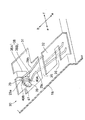
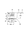
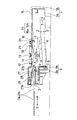
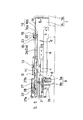
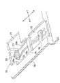
- FIG. 1, FIG. 2, FIG. 3A, and FIG. 3B show the main part of a disk drive that is an embodiment of the present invention.
- This is a Blu-ray Disc type recorder (or player) equipped with a disk slot loading mechanism.
- the spring seat 30 has an L-shaped frame 38 left uncut by forming the first opening 31 in the metal plate lid plate 1B.
- the L-shaped frame 38 includes a support plate 38A formed integrally with the edge of the first opening 31 and a support shaft 38B that is bent at a right angle from the tip of the support plate 38A.
- the L-shaped frame 38 is raised to the flap 27 side by bending the base of the support plate 38A.
- a stopper portion 39 protruding from the flap side edge 40A toward the flap 27 is provided at the tip of the support shaft 38B. Between the stopper portion 39 of the support shaft plate 38B and the support plate 38A, a support shaft main body 40 that receives and supports the coil portion 29a of the presser spring 29 is provided.
- the configuration other than the above is almost the same as the configuration shown in FIGS. Therefore, below, the same code
- the side edge of the stopper portion 39 facing the spindle main body 40 is inclined at a predetermined inclination angle ⁇ (for example, 45 °) to form an inclined side edge 39a. Is formed.
- An inclined guide edge 41 is formed by notching the front end side of the cover plate side edge 40B of the support plate 38B with respect to the support shaft main body 40 and inclining at a predetermined inclination angle ⁇ (for example, 30 °).
- the flap side edge 40A and the cover plate side edge 40B of the spindle body 40 are formed in parallel to each other.
- the width h1 of the spindle main body 40 is set to be larger than the width h2 of the coil portion 29a.
- the protrusion height t ⁇ b> 1 of the stopper portion 39 is set to be larger than the outer diameter t ⁇ b> 2 of the wire forming the presser spring 29.
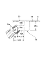
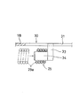
- the coil portion 29a of the presser spring 29 is placed at the tip of the support shaft 38B along the inclined side edge 39a and the inclined guide edge 41 of the stopper portion 39. Apply. Then, as shown in FIG. 3B, the coil portion 29 a is externally fitted to the spindle main body 40. Subsequently, as shown in FIG. 1, one rod portion 29 b is brought into contact with the partition plate 35, and the other rod portion 29 c is hooked on the protruding piece 36 and temporarily fixed. Then, after attaching the flap 27 to the cover plate 1B, the other rod part 29c is removed from the protruding piece 36 and brought into contact with the flap 27 (see FIG. 5).
- the coil portion 29a of the holding spring 29 when the coil portion 29a of the holding spring 29 is manually fitted to the spindle main body 40 of the spindle plate 38B, it is formed at the tip of the spindle plate 38B.
- the inclined side edge 39a and the inclined guide edge 41 of the stopper portion 39 extend in an oblique direction so as to be separated from the cover plate 1B. Therefore, the coil portion 29a of the pressing spring 29 can be easily fitted on the spindle body 40 of the spindle plate 38B along the inclined side edge 39a and the inclined guide edge 41 of the stopper portion 39.
- the protruding height t1 of the stopper portion 39 integrally projecting from the tip of the support shaft 38B is set to be larger than the outer diameter t2 of the wire forming the holding spring 29.
- the width h1 of the spindle main body 40 is set to be larger than the width h2 of the coil portion 29a. Therefore, as shown in FIG. 3B, when attaching the flap 27 to the cover plate 1B, even if an excessive load M is applied to the coil portion 29a that is externally fitted to the spindle body 40, The coil portion 29a does not come off from the spindle main body 40. Therefore, the attachment state of the presser spring 29 to the spring seat 30 can be reliably maintained. Furthermore, the attaching operation of the flap 27 can be performed efficiently.
- the L-shaped frame 38 including the support plate 38A and the support shaft plate 38B is left uncut when the first opening 31 is formed in the metal plate lid plate 1B. Therefore, when forming the L-shaped frame 38, the number of parts does not increase, and the production cost can be reduced.
- the disk insertion port is formed on the front surface of the loader chassis including the chassis main body and the cover plate, and the traverse chassis on which the turntable and the optical pickup are mounted is disposed in the loader chassis.
- a transport roller is disposed at the front of the chassis body so as to be able to rotate forward and backward, facing the disk insertion slot, and a flap is disposed at the back side of the lid plate so as to be rotatable around a pivot shaft so as to face the transport roller.
- a pressing spring for urging the flap toward the conveying roller is attached to the spring seat of the cover plate, and the disk slotted into the disk insertion slot is sandwiched between the conveying roller and the flap and sent into the loader chassis.
- the disc is rotated at high speed on a turntable and the information recorded on the disc is read with an optical pickup.
- a support shaft that bends at right angles from the front end of the support plate, and an L-shaped frame is caused on the flap side by bending the base of the support plate, and the flap starts from the front end of the flap side edge of the support plate.
- a stopper portion protruding to the side is provided, and a support shaft body that receives the coil portion of the holding spring is provided between the stopper portion of the support shaft plate and the support plate.
- An inclined guide edge is formed by notching the tip side of the shaft body, and the coil portion of the holding spring is fitted on the spindle body along the inclined guide edge and extends from both ends of the coil portion of the holding spring. Engage the two rod parts with the lid plate and the flap. It is characterized in that.
- the inclined guide edge formed at the tip of the spindle plate is inclined so that it is separated from the lid plate. It extends to. Therefore, it is possible to easily fit the coil portion of the holding spring to the spindle body of the spindle plate along the inclined guide edge.
- a stopper is provided at the tip of the support plate even if a tool or finger is caught on the coil of the holding spring. Therefore, the coil part does not come off from the support shaft, and the flap can be attached efficiently.
- the L-shaped frame composed of the support plate and the support shaft plate is left uncut when the opening is formed in the metal plate lid plate. Therefore, the number of parts does not increase when forming the L-shaped frame. In addition, production costs can be reduced.
- the width of the spindle body is set to be larger than the width of the coil portion, and the protruding height of the stopper portion is set to be larger than the outer diameter of the wire forming the holding spring. It is characterized by that.
- the width of the spindle main body is set larger than the width of the coil portion.
- the protruding height of the stopper portion is set to be larger than the outer diameter of the wire material forming the holding spring. Therefore, the coil part does not come off from the spindle body, and the attachment state of the presser spring to the spring seat can be reliably maintained.
Landscapes
- Feeding And Guiding Record Carriers (AREA)
Abstract
L'invention porte sur un lecteur de disque qui comprend un châssis de chargeur, un rouleau de transport, un volet et des ressorts de maintien. Un disque, qui est inséré dans une ouverture d'insertion de disque créée sur la surface avant du châssis de chargeur, est pris en sandwich par le rouleau de transport et le volet et est transporté dans le châssis de chargeur par le rouleau de transport. Des sièges de ressort sont disposés sur la plaque de toit du châssis de chargeur. Les ressorts de maintien sont montés sur les sièges de ressort de façon à solliciter le volet vers le rouleau de transport. Le siège de ressort comprend un cadre en forme de L. Le cadre en forme de L comprend une plaque de support, qui est formée d'un seul tenant avec un bord de la partie d'ouverture disposée sur la plaque de toit, et une plaque d'appui, qui est courbée à un angle droit au niveau de l'extrémité avant de ladite plaque de support, et est tirée pour monter vers le volet par courbure de la base de la plaque de support. La plaque d'appui comprend une section d'arrêt, qui fait saillie de l'extrémité avant côté volet de la plaque d'appui vers le volet, et un corps d'appui. Des bords de guidage inclinés sont formés par découpe des bords avant côté plaque de toit de la plaque d'appui. La section à enroulement du ressort de maintien est ajustée autour du corps d'appui le long des bords de guidage inclinés.
Priority Applications (3)
| Application Number | Priority Date | Filing Date | Title |
|---|---|---|---|
| US13/882,805 US20130227593A1 (en) | 2010-11-02 | 2011-10-31 | Disk device |
| EP11837964.3A EP2637168A1 (fr) | 2010-11-02 | 2011-10-31 | Lecteur de disque |
| CN2011800523009A CN103180905A (zh) | 2010-11-02 | 2011-10-31 | 盘片装置 |
Applications Claiming Priority (2)
| Application Number | Priority Date | Filing Date | Title |
|---|---|---|---|
| JP2010-246720 | 2010-11-02 | ||
| JP2010246720A JP2012099185A (ja) | 2010-11-02 | 2010-11-02 | ディスク装置 |
Publications (1)
| Publication Number | Publication Date |
|---|---|
| WO2012060314A1 true WO2012060314A1 (fr) | 2012-05-10 |
Family
ID=46024427
Family Applications (1)
| Application Number | Title | Priority Date | Filing Date |
|---|---|---|---|
| PCT/JP2011/075037 Ceased WO2012060314A1 (fr) | 2010-11-02 | 2011-10-31 | Lecteur de disque |
Country Status (5)
| Country | Link |
|---|---|
| US (1) | US20130227593A1 (fr) |
| EP (1) | EP2637168A1 (fr) |
| JP (1) | JP2012099185A (fr) |
| CN (1) | CN103180905A (fr) |
| WO (1) | WO2012060314A1 (fr) |
Citations (5)
| Publication number | Priority date | Publication date | Assignee | Title |
|---|---|---|---|---|
| JPH02140764U (fr) * | 1989-04-27 | 1990-11-26 | ||
| JPH03106756U (fr) * | 1990-02-19 | 1991-11-05 | ||
| JPH07240056A (ja) * | 1994-02-28 | 1995-09-12 | Mitsubishi Electric Corp | ディスク装置の媒体昇降機構 |
| JP2007080337A (ja) | 2005-09-13 | 2007-03-29 | Mitsubishi Electric Corp | ディスク装置及びディスクローディング機構 |
| JP2010080020A (ja) * | 2008-09-29 | 2010-04-08 | Orion Denki Kk | 記憶媒体再生装置又は記憶媒体の記録及び再生装置における記憶媒体搬送機構 |
Family Cites Families (5)
| Publication number | Priority date | Publication date | Assignee | Title |
|---|---|---|---|---|
| UA53638C2 (uk) * | 1996-03-29 | 2003-02-17 | Хьорманн Кг Брокхаген | Стельові секційні ворота |
| JP3325820B2 (ja) * | 1997-11-29 | 2002-09-17 | タナシン電機株式会社 | ディスク再生機のディスク搬送装置 |
| JP3106756U (ja) * | 2004-07-23 | 2005-01-20 | 船井電機株式会社 | ディスク再生機能付きテレビジョンおよびディスク再生装置 |
| JP2007066430A (ja) * | 2005-08-31 | 2007-03-15 | Orion Denki Kk | ガイドシャフト保持機構及びガイドシャフト保持機構を備えた光ディスクドライブ |
| JP3892021B1 (ja) * | 2005-09-08 | 2007-03-14 | 三菱電機株式会社 | ディスクローディング装置及びディスク装置 |
-
2010
- 2010-11-02 JP JP2010246720A patent/JP2012099185A/ja active Pending
-
2011
- 2011-10-31 US US13/882,805 patent/US20130227593A1/en not_active Abandoned
- 2011-10-31 CN CN2011800523009A patent/CN103180905A/zh active Pending
- 2011-10-31 WO PCT/JP2011/075037 patent/WO2012060314A1/fr not_active Ceased
- 2011-10-31 EP EP11837964.3A patent/EP2637168A1/fr not_active Withdrawn
Patent Citations (5)
| Publication number | Priority date | Publication date | Assignee | Title |
|---|---|---|---|---|
| JPH02140764U (fr) * | 1989-04-27 | 1990-11-26 | ||
| JPH03106756U (fr) * | 1990-02-19 | 1991-11-05 | ||
| JPH07240056A (ja) * | 1994-02-28 | 1995-09-12 | Mitsubishi Electric Corp | ディスク装置の媒体昇降機構 |
| JP2007080337A (ja) | 2005-09-13 | 2007-03-29 | Mitsubishi Electric Corp | ディスク装置及びディスクローディング機構 |
| JP2010080020A (ja) * | 2008-09-29 | 2010-04-08 | Orion Denki Kk | 記憶媒体再生装置又は記憶媒体の記録及び再生装置における記憶媒体搬送機構 |
Also Published As
| Publication number | Publication date |
|---|---|
| JP2012099185A (ja) | 2012-05-24 |
| CN103180905A (zh) | 2013-06-26 |
| EP2637168A1 (fr) | 2013-09-11 |
| US20130227593A1 (en) | 2013-08-29 |
Similar Documents
| Publication | Publication Date | Title |
|---|---|---|
| JP2012027967A (ja) | ディスク搬送機構及びディスク駆動装置 | |
| JP2010080020A (ja) | 記憶媒体再生装置又は記憶媒体の記録及び再生装置における記憶媒体搬送機構 | |
| US20130227593A1 (en) | Disk device | |
| JP4597503B2 (ja) | ディスク装置 | |
| JP2012009104A (ja) | ディスククランプ機構及びディスク駆動装置 | |
| JP4084340B2 (ja) | 車載用ディスク装置 | |
| JP2012099186A (ja) | ディスク装置 | |
| JP2005116029A (ja) | ディスクプレーヤのディスク搬送機構 | |
| JP4184285B2 (ja) | ディスク装置 | |
| JP4785875B2 (ja) | 光ピックアップのガイドシャフト位置決め装置 | |
| JP6053259B2 (ja) | ディスク装置 | |
| JP5100575B2 (ja) | ディスク再生装置 | |
| JP3674493B2 (ja) | ディスク装置 | |
| JP2006164455A (ja) | ディスクローディング装置 | |
| JP4156550B2 (ja) | ディスク再生装置 | |
| JP5216538B2 (ja) | ディスク再生装置 | |
| JP4736865B2 (ja) | ディスク装置のスロットローディング機構 | |
| JP2886001B2 (ja) | ディスクプレーヤ | |
| JP5136092B2 (ja) | ディスク再生装置 | |
| JP3818095B2 (ja) | 光ディスク装置 | |
| JP4848328B2 (ja) | ディスク装置 | |
| JP3765668B2 (ja) | ディスクプレーヤ | |
| JP3823769B2 (ja) | 光ディスク装置 | |
| US20090235287A1 (en) | Conveyance Device and Recording Meduim Drive Device | |
| JP4557645B2 (ja) | ディスクプレーヤ装置 |
Legal Events
| Date | Code | Title | Description |
|---|---|---|---|
| 121 | Ep: the epo has been informed by wipo that ep was designated in this application |
Ref document number: 11837964 Country of ref document: EP Kind code of ref document: A1 |
|
| DPE1 | Request for preliminary examination filed after expiration of 19th month from priority date (pct application filed from 20040101) | ||
| WWE | Wipo information: entry into national phase |
Ref document number: 2011837964 Country of ref document: EP |
|
| WWE | Wipo information: entry into national phase |
Ref document number: 13882805 Country of ref document: US |
|
| NENP | Non-entry into the national phase |
Ref country code: DE |