WO2012063328A1 - 車両ブレーキシステム - Google Patents
車両ブレーキシステム Download PDFInfo
- Publication number
- WO2012063328A1 WO2012063328A1 PCT/JP2010/069994 JP2010069994W WO2012063328A1 WO 2012063328 A1 WO2012063328 A1 WO 2012063328A1 JP 2010069994 W JP2010069994 W JP 2010069994W WO 2012063328 A1 WO2012063328 A1 WO 2012063328A1
- Authority
- WO
- WIPO (PCT)
- Prior art keywords
- brake
- negative pressure
- pedal
- engine
- driver
- Prior art date
- Legal status (The legal status is an assumption and is not a legal conclusion. Google has not performed a legal analysis and makes no representation as to the accuracy of the status listed.)
- Ceased
Links
Images




Classifications
-
- B—PERFORMING OPERATIONS; TRANSPORTING
- B60—VEHICLES IN GENERAL
- B60W—CONJOINT CONTROL OF VEHICLE SUB-UNITS OF DIFFERENT TYPE OR DIFFERENT FUNCTION; CONTROL SYSTEMS SPECIALLY ADAPTED FOR HYBRID VEHICLES; ROAD VEHICLE DRIVE CONTROL SYSTEMS FOR PURPOSES NOT RELATED TO THE CONTROL OF A PARTICULAR SUB-UNIT
- B60W10/00—Conjoint control of vehicle sub-units of different type or different function
- B60W10/18—Conjoint control of vehicle sub-units of different type or different function including control of braking systems
- B60W10/184—Conjoint control of vehicle sub-units of different type or different function including control of braking systems with wheel brakes
-
- B—PERFORMING OPERATIONS; TRANSPORTING
- B60—VEHICLES IN GENERAL
- B60T—VEHICLE BRAKE CONTROL SYSTEMS OR PARTS THEREOF; BRAKE CONTROL SYSTEMS OR PARTS THEREOF, IN GENERAL; ARRANGEMENT OF BRAKING ELEMENTS ON VEHICLES IN GENERAL; PORTABLE DEVICES FOR PREVENTING UNWANTED MOVEMENT OF VEHICLES; VEHICLE MODIFICATIONS TO FACILITATE COOLING OF BRAKES
- B60T17/00—Component parts, details, or accessories of power brake systems not covered by groups B60T8/00, B60T13/00 or B60T15/00, or presenting other characteristic features
- B60T17/02—Arrangements of pumps or compressors, or control devices therefor
-
- B—PERFORMING OPERATIONS; TRANSPORTING
- B60—VEHICLES IN GENERAL
- B60W—CONJOINT CONTROL OF VEHICLE SUB-UNITS OF DIFFERENT TYPE OR DIFFERENT FUNCTION; CONTROL SYSTEMS SPECIALLY ADAPTED FOR HYBRID VEHICLES; ROAD VEHICLE DRIVE CONTROL SYSTEMS FOR PURPOSES NOT RELATED TO THE CONTROL OF A PARTICULAR SUB-UNIT
- B60W10/00—Conjoint control of vehicle sub-units of different type or different function
- B60W10/04—Conjoint control of vehicle sub-units of different type or different function including control of propulsion units
- B60W10/06—Conjoint control of vehicle sub-units of different type or different function including control of propulsion units including control of combustion engines
-
- F—MECHANICAL ENGINEERING; LIGHTING; HEATING; WEAPONS; BLASTING
- F02—COMBUSTION ENGINES; HOT-GAS OR COMBUSTION-PRODUCT ENGINE PLANTS
- F02N—STARTING OF COMBUSTION ENGINES; STARTING AIDS FOR SUCH ENGINES, NOT OTHERWISE PROVIDED FOR
- F02N11/00—Starting of engines by means of electric motors
- F02N11/08—Circuits specially adapted for starting of engines
- F02N11/0814—Circuits specially adapted for starting of engines comprising means for controlling automatic idle-start-stop
- F02N11/0844—Circuits specially adapted for starting of engines comprising means for controlling automatic idle-start-stop with means for restarting the engine directly after an engine stop request, e.g. caused by change of driver mind
-
- Y—GENERAL TAGGING OF NEW TECHNOLOGICAL DEVELOPMENTS; GENERAL TAGGING OF CROSS-SECTIONAL TECHNOLOGIES SPANNING OVER SEVERAL SECTIONS OF THE IPC; TECHNICAL SUBJECTS COVERED BY FORMER USPC CROSS-REFERENCE ART COLLECTIONS [XRACs] AND DIGESTS
- Y02—TECHNOLOGIES OR APPLICATIONS FOR MITIGATION OR ADAPTATION AGAINST CLIMATE CHANGE
- Y02T—CLIMATE CHANGE MITIGATION TECHNOLOGIES RELATED TO TRANSPORTATION
- Y02T10/00—Road transport of goods or passengers
- Y02T10/10—Internal combustion engine [ICE] based vehicles
- Y02T10/40—Engine management systems
Definitions
- the present invention relates to a vehicle brake system that generates a braking force on a vehicle in accordance with a driver's brake operation.
- a vehicle brake system in order to reduce an operation burden at the time of a driver's brake operation, a vehicle brake system is provided with a booster that uses an intake negative pressure of an engine.
- the booster assists the depressing operation of the brake pedal by utilizing the difference between the brake negative pressure due to the intake negative pressure of the engine and the atmospheric pressure. For this reason, when the brake operation is performed while the engine is stopped, the brake negative pressure of the booster decreases, so that there is a possibility that the depression operation of the brake pedal cannot be assisted. Therefore, conventionally, a technique for recovering the brake negative pressure by starting a stopped engine is known. For example, this technique is disclosed in Patent Document 1 below.
- Patent Document 2 discloses a technique for making the valve opening of the throttle valve smaller than that in the idle state when the engine stopped during traveling is restarted.
- Patent Document 3 discloses a technique for releasing the idle stop and starting the engine when the vehicle speed is equal to or higher than a predetermined value and the brake negative pressure of the booster is equal to or lower than the predetermined value.
- the present invention provides a vehicle brake system that can improve the disadvantages of the conventional example and recover the brake negative pressure while maintaining the braking force in accordance with the intention of the driver. Objective.
- the present invention provides a vehicle brake system for starting the engine to recover the brake negative pressure of the booster connected to the intake path of the engine.
- the opening degree of the throttle valve of the engine is controlled to the valve opening side when the engine is started.
- the brake negative pressure recovery control by the valve opening control of the throttle valve is performed during the driver's brake depression operation.
- the present invention provides a vehicle brake system that starts the engine to recover the brake negative pressure of the booster connected to the intake path of the engine. Therefore, when the engine is started, a pedal reaction force opposite to the pedal depression force of the driver is generated with respect to the brake pedal.
- the pedal reaction force be generated during the driver's brake depression operation.
- the vehicle brake system according to the present invention slows down the generation speed of the intake air speed by opening the valve opening of the throttle valve to the valve opening side when starting the engine. Therefore, this vehicle brake system can delay the recovery speed of the brake negative pressure of the booster.
- the vehicle brake system according to the present invention generates an excessive pedal effort unintended by the driver by generating a pedal reaction force opposite to the driver's pedal effort against the brake pedal when the engine is started. Can be suppressed.
- the vehicle brake system when the brake negative pressure is recovered, a situation in which the brake pedal being depressed is pushed against the driver's intention is avoided. Therefore, the vehicle brake system can recover the brake negative pressure while generating the braking force in accordance with the driver's intention, and the brake pedal is pushed in along with the recovery of the brake negative pressure. It also eliminates a sense of incongruity in operation.
- FIG. 1 is a diagram showing a configuration of a first embodiment of a vehicle brake system according to the present invention.
- FIG. 2 is a flowchart illustrating the control operation of the vehicle brake system according to the first embodiment.
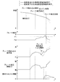
- FIG. 3 is a time chart illustrating the control operation of the vehicle brake system of the first embodiment.
- FIG. 4 is a diagram showing a configuration of a vehicle brake system according to a second embodiment of the present invention.
- FIG. 5 is a flowchart for explaining the control operation of the vehicle brake system of the second embodiment.
- FIG. 6 is a time chart illustrating the control operation of the vehicle brake system of the second embodiment.
- Example 1 A vehicle brake system according to a first embodiment of the present invention will be described with reference to FIGS.
- Reference numeral 1 in FIG. 1 indicates the vehicle brake system of the present embodiment.
- a system capable of adjusting the wheel braking force for each of the wheels W FL , W FR , W RL , and W RR will be described as an example.
- the vehicle brake system 1 includes a brake pedal 11 operated by a driver, a booster (so-called brake booster) 12 that doubles the pedal effort input to the brake pedal 11, and a booster 12 that doubles the booster 12.
- the master cylinder 13 for converting the pedal depression force to the brake fluid pressure (brake fluid pressure) and the converted brake fluid pressure can be adjusted for each wheel W FL , W FR , W RL , W RR.
- a hydraulic pressure adjusting device (hereinafter referred to as a “brake actuator”) 14 and a brake hydraulic pressure that has passed through the brake actuator 14 are supplied to generate braking forces on the respective wheels W FL , W FR , W RL , W RR.
- an electronic control unit (ECU) 21 controls the brake actuator 14 to generate a requested wheel driving force for desired wheels W FL , W FR , W RL , W RR .
- the booster 12 includes a negative pressure chamber and an atmospheric pressure chamber.
- the booster 12 creates a difference between the negative pressure in the negative pressure chamber and the atmospheric pressure in the atmospheric pressure chamber by setting the negative pressure chamber to a negative pressure by the intake negative pressure of the engine 50, and operates according to the difference.
- the vehicle brake system 1 is provided with a negative pressure pipe 16 that connects an intake path 51 of the engine 50 (a path from an air cleaner (not shown) to the intake manifold 52) and the negative pressure chamber of the booster 12.
- the negative pressure pipe 16 is illustrated as being connected to the intake manifold 52, but may be connected anywhere on the intake path 51 as long as it is a well-known place in this technical field.
- the booster 12 operates by utilizing the intake negative pressure of the engine 50. Therefore, in order to continue to maintain the brake negative pressure in the negative pressure chamber necessary for the operation, it is necessary that the intake negative pressure is continuously generated by the operation of the engine 50.
- the engine 50 may be stopped during traveling to travel inertially.
- the inertia traveling may be performed while the power transmission between the engine 50 and the drive wheels W RL and W RR is possible, or may be performed such that the power transmission cannot be performed.
- the inertial running in the state where the power transmission is impossible is executed by releasing the power connection / disconnection portion of the power transmission device between the engine 50 and the drive wheels WRL , WRR .
- the power transmission device is a device that transmits the power of the engine 50 such as a transmission to the drive wheels W RL and W RR .
- the transmission is the automatic transmission 60
- the input clutch 61 in the transmission main body, the lock-up clutch 62 of the torque converter, and the like function as a power connection / disconnection portion. Since the automatic transmission 60 is in a neutral state by releasing the input clutch 61, power transmission between the engine 50 and the drive wheels WRL and WRR cannot be performed. Further, when the lockup clutch 62 is released, power cannot be transmitted between the engine 50 and the automatic transmission 60, so that power is not transmitted between the engine 50 and the drive wheels WRL , WRR .
- the pressure in the intake passage 51 becomes atmospheric pressure. Therefore, when the driver depresses the brake in that state, the brake negative pressure in the negative pressure chamber decreases in the booster 12. I will do it. Accordingly, the auxiliary function by the booster 12 does not work and the brake pedal 11 becomes heavy, so that the driver strongly performs the brake depression operation with a larger pedal depression force than when the auxiliary function is working. For this reason, when the brake negative pressure falls below a predetermined value, the electronic control unit 21 drives the starter motor 56 to restart the engine 50 and generates an intake negative pressure so that the brake negative pressure equal to or higher than the predetermined value is generated. To be maintained.
- the predetermined value is, for example, the minimum brake negative pressure at which the auxiliary function by the booster 12 that is required can be exhibited.
- the brake negative pressure is recovered by restarting the stopped engine 50. Yes.
- the restart control of the engine 50 at this time is performed with the magnitude of the brake negative pressure as a starting point, during the restart control, the brake depressing operation that contributes to the decrease of the brake negative pressure is performed by the driver. It may have been done by.
- the restart control of the engine 50 for generating the intake negative pressure is performed during the brake depression operation, the difference from the atmospheric pressure increases as the brake negative pressure increases, so the brake pedal 11 during the brake depression operation is increased. May be pushed in the depressing direction, and an excessive braking force unintended by the driver may be generated.
- the brake pedal 11 since the intake negative pressure is quickly generated when the engine 50 is restarted, the brake pedal 11 may be pushed at once by the brake negative pressure recovered in the same manner, and sudden braking that is not intended by the driver is performed. There is also a risk of causing it.
- the vehicle brake system 1 prevents the braking force unintended by the driver from being generated by the restart control of the engine 50 for generating the intake negative pressure. Specifically, by delaying the recovery speed of the intake negative pressure (brake negative pressure), that is, the generation speed, the brake pedal 11 is brought to a depth unintended by the driver when the engine 50 is restarted. Don't push in too fast. Accordingly, the vehicle brake system 1 is provided with a negative pressure generation delay device that delays the generation speed (recovery speed) of intake negative pressure (brake negative pressure). The negative pressure generation delay device is operated when performing restart control of the engine 50 for generating intake negative pressure during traveling (during coasting) and during brake depression operation.
- the throttle valve 53 and the valve actuator 54 that opens and closes the throttle valve 53 are used as a negative pressure generation delay device.
- the electronic control device 21 drives the valve actuator 54 to bring the throttle valve 53 to the required valve opening when performing the restart control of the engine 50 for generating the intake negative pressure during the inertial running and the brake depression operation. By operating, excessive braking force and sudden braking unintended by the driver are suppressed.
- this control operation will be described based on the flowchart of FIG. 2 and the time chart of FIG.
- the electronic control unit 21 first determines whether or not the engine 50 is stopped (step ST1).
- stop here means when the fuel is not ignited (in the case of a diesel engine, the fuel does not ignite).
- the electronic control device 21 terminates the control operation when the engine 50 is operating, while the brake negative pressure Pa ( ⁇ 0) in the negative pressure chamber of the booster 12 is determined when the engine 50 is stopped.
- the absolute value is compared with the absolute value of the predetermined value P1 ( ⁇ 0) described above (step ST2).
- a detection value of a negative pressure detection device 17 such as a pressure sensor is used.
- the electronic control device 21 ends the present control operation because a sufficient brake negative pressure Pa is secured.
- the electronic control unit 21 gives an instruction to restart the engine 50 if the absolute value of the brake negative pressure Pa is smaller than the absolute value of the predetermined value P1, that is, if the brake negative pressure Pa is lower than the predetermined value P1. (Step ST3).
- the electronic control unit 21 determines whether or not the vehicle is traveling (ie, coasting) (step ST4). If the vehicle is traveling, it is determined whether or not the driver is depressing the brake. (Step ST5). To determine whether or not the vehicle is running, the detection value of the vehicle speed detection device 71 such as a vehicle speed sensor or a wheel speed sensor may be used. Moreover, what is necessary is just to utilize the detected value of the pedal operation amount detection apparatus 18 which can detect the operation amount of the brake pedal 11 for determination of whether the brake depression operation is in progress.
- the pedal operation amount detection device 18 uses a pedal position detection sensor capable of detecting the depression position of the brake pedal 11 as long as it detects the depression amount of the brake pedal 11. On the other hand, if this pedal operation amount detection device 18 detects a driver's pedal effort on the brake pedal 11, a pedal effort sensor such as a pressure sensor is used.
- step ST8 the electronic control unit 21 proceeds to step ST8 to be described later, and restarts the engine 50 without performing the intake negative pressure generation speed delay control. Let it run. This is because when the vehicle is stopped, even if the brake negative pressure Pa recovers during the brake depression operation, excessive braking force or sudden braking unintended by the driver is not generated in the vehicle. Further, if the brake depression operation is not performed, the vehicle does not generate excessive braking force or sudden braking that is not intended by the driver even during traveling.
- the electronic control unit 21 calculates a required valve opening (required throttle opening) of the throttle valve 53 (step ST6).
- the required throttle opening is larger than the required throttle opening when restarting the engine 50 without performing the intake negative pressure generation speed delay control (the required throttle opening at the time of engine restart known in this technical field). Open the valve.
- the brake negative pressure Pa is not sufficiently recovered due to the shortage of the intake negative pressure, and the desired braking force cannot be generated by the brake depression operation. there is a possibility.
- the required throttle opening in step ST6 may be set to an average value of the required throttle opening when the driver who is traveling with the power of the engine 50 performs the accelerator depression operation (that is, the acceleration operation). Therefore, the electronic control device 21 is made to learn the average value of the required throttle opening degree according to the driver's accelerator depression operation while traveling with the power of the engine 50. At that time, learning may be performed based on the command value of the required throttle opening, or learning may be performed based on the actual throttle opening based on the detection value of the valve opening detecting device 55 such as a valve opening sensor. .
- the electronic control unit 21 instructs the required throttle opening in step ST6 as a required value of the throttle valve 53 when the engine is restarted (step ST7). Then, the electronic control unit 21 controls the throttle valve 53 to the required throttle opening, and restarts the engine 50 (step ST8).
- the brake negative pressure Pa1 ( ⁇ P1) is maintained until the driver performs a brake depression operation.
- the brake depressing operation amount increases, and at the same time, the brake fluid pressure (braking force) increases and the deceleration of the vehicle increases.
- the brake negative pressure Pa in the negative pressure chamber decreases.
- the decrease in the brake negative pressure Pa reduces the degree of doubling of the pedal depressing force by the booster 12, so that the feeling of depressing operation of the brake pedal 11 by the driver becomes heavy.
- the driver's brake depression operation amount decreases, and the brake fluid pressure (braking force) decreases.
- the driver depresses the brake pedal 11 as much as the depressing operation feeling becomes heavy, the driver's brake depressing operation amount (pedal depressing force) increases again.
- the auxiliary function by the booster 12 is not sufficiently functioning, the brake fluid pressure (braking force) at that time does not increase to a magnitude corresponding to the brake depression operation amount (pedal depression force).
- the brake negative pressure Pa falls below a predetermined value P1 by the driver's brake operation
- the brake negative pressure Pa is recovered by restarting the engine 50.
- the required throttle opening is increased to the valve opening side than when the brake depression operation is not performed, and the engine 50 is restarted.
- the intake negative pressure increases more slowly than before in the engine 50 as the engine 50 is restarted.
- the brake negative pressure Pa in the negative pressure chamber of the booster 12 gradually increases in accordance with the generation speed of the intake negative pressure. Therefore, the degree of doubling of the pedal depressing force by the booster 12 is gradually increased.
- the driver feels that the feeling of depressing the brake pedal 11 gradually becomes lighter. Since the brake pedal 11 during the brake depression operation is pushed more than necessary with the recovery of the brake negative pressure Pa, it is not intended by the driver. A situation in which excessive braking force is generated in the vehicle can be avoided.
- the vehicle brake system 1 since the vehicle brake system 1 does not rapidly recover the brake negative pressure Pa, the brake pedal 11 during the brake depression operation is not pushed in at once with the recovery of the brake negative pressure Pa. Therefore, the vehicle brake system 1 can avoid sudden braking due to an excessive braking force not intended by the driver. That is, the vehicle brake system 1 can recover the brake negative pressure Pa in a state where a braking force in accordance with the driver's intention is generated. Furthermore, this vehicle brake system 1 can also eliminate the uncomfortable feeling in operation that the brake pedal 11 is pushed in along with the recovery of the brake negative pressure Pa. Furthermore, this vehicle brake system 1 can avoid the occurrence of excessive braking force or sudden braking that is not intended by the driver, so that the brake negative pressure Pa can be recovered while the vehicle is in a stable posture. Can be planned. [Example 2]
- Embodiment 2 of a vehicle brake system according to the present invention will be described with reference to FIGS.
- Reference numeral 1 in FIG. 4 indicates the vehicle brake system of the present embodiment.
- the vehicle brake system 1 includes a brake pedal 11, booster 12, a master cylinder 13, a brake actuator 14 and the braking device 15 FL, 15 FR, 15 RL , 15 RR. These are the same as the vehicle brake system 1 of the first embodiment.
- the driver when the restart control of the engine 50 for generating the intake negative pressure is performed during the inertial traveling and the brake depression operation, the driver is caused by the recovery of the brake negative pressure accompanying the restart of the engine 50. In order not to generate unintended braking force, the generation speed of the intake negative pressure (brake negative pressure Pa) was delayed.
- the driver instead of the generation speed delay control of the intake negative pressure or together with the generation speed delay control, the driver does not intend to control the recovery of the brake negative pressure Pa with the following device. Avoid generating power.
- the vehicle brake system 1 is provided with a pedal reaction force generating device 19 that generates a pedal reaction force Pb opposite to the driver's pedaling force direction with respect to the brake pedal 11.
- the pedal reaction force generator 19 is disposed between the brake pedal 11 and the booster 12.
- the pedal reaction force generator 19 includes, for example, a hydraulic or electric actuator.
- the electronic control device 21 controls an electric actuator such as an electric motor and the required pedal reaction force Pb corresponding to the pedal depression force Px (n) with respect to the brake pedal 11. (N) is generated.
- an electric actuator such as an electric motor
- Pb the required pedal reaction force
- N the required pedal reaction force
- the electronic control unit 21 calculates a required pedal reaction force Pb (n) to the brake pedal 11 (step ST17), and uses the required pedal reaction force Pb (n) as a command value for the pedal reaction force generation device 19. This is output (step ST18).
- the output timing of the required pedal reaction force Pb (n) will generate a braking force against the driver's intention even if it is late until the brake negative pressure Pa is recovered even if it is late. It is preferable to set it until the brake negative pressure Pa returns to the magnitude.
- the required pedal reaction force Pb (n) before the engine 50 is restarted in consideration of the response delay until the required pedal reaction force Pb (n) actually acts on the brake pedal 11.
- the required pedal reaction force Pb (n) is actually acting on the brake pedal 11 when the brake negative pressure Pa begins to recover.
- the braking force can be increased by further pressing the brake pedal 11 to increase the pedal depression force Px. For this reason, when the brake pedal 11 is depressed, even if the brake negative pressure Pa is recovered, the driver's depression operation of the brake pedal 11 is performed by the requested pedal reaction force Pb (n) currently output. The feeling may become heavy. Accordingly, at this time, the required pedal reaction force Pb (n) is decreased from that currently output so as not to give an uncomfortable feeling to the brake depression operation.
- the electronic control unit 21 is made to acquire information on the pedal effort Px (n + 1) again (step ST19), and the pedal effort Px (n + 1) exceeds the previously obtained pedal effort Px (n). Whether or not the brake pedal 11 is stepped on by the driver is determined (step ST20).
- the electronic control unit 21 increments n because the brake pedal 11 is depressed (step ST21), and returns to step ST17 to return to that step.
- a required pedal reaction force Pb (n + 1) based on the pedal depression force Px (n + 1) is obtained.
- the required pedal reaction force Pb (n + 1) is calculated based on Equation 1 below.
- ⁇ Pb is a pedal reaction force reduction amount for preventing a feeling of strangeness such as a heavy stepping operation feeling when the brake pedal 11 is stepped on, and is determined based on, for example, the following formula 2.
- ⁇ in Expression 2 is an adjustment coefficient of the pedal reaction force reduction amount ⁇ Pb, and does not give the driver a sense of discomfort, and the braking force against the driver's intention when the brake negative pressure Pa is recovered. To a size that does not generate The adjustment coefficient ⁇ may be set in advance based on experiments and simulations.
- step ST20 if the pedal effort Px (n) remains constant and does not change or decreases, the pedal effort Px (n + 1) is less than or equal to the pedal effort Px (n) in step ST20. Determined. Even if it is determined that the pedal effort Px (n + 1) is greater than the pedal effort Px (n), the subsequent pedal effort Px (n + 1) will eventually increase as the brake negative pressure Pa decreases. There is no change to Px (n). Therefore, in this case, it is determined in step ST20 that the pedal effort Px (n + 1) is equal to or less than the pedal effort Px (n).
- step ST20 If a negative determination is made in step ST20, the electronic control unit 21 restarts the engine 50 as in the conventional case (step ST22).
- the brake negative pressure Pa is reduced by the driver's brake depression operation during inertial driving, and the driver's feeling of depression of the brake pedal 11 becomes heavy.
- the brake negative pressure Pa falls below a predetermined value P1 due to the driver's brake operation, the brake negative pressure Pa is recovered by restarting the engine 50.
- the pedal reaction force generation device 19 outputs the required pedal reaction force Pb (n), thereby allowing the driver to The pedal depression force Px is reduced so that an excessive pedal depression force Px does not act on the brake pedal 11.
- the vehicle brake system 1 can recover the brake negative pressure Pa in a state where the braking force in accordance with the driver's intention is generated. Furthermore, the vehicle brake system 1 can also eliminate the uncomfortable feeling in operation that the brake pedal 11 is pushed in along with the recovery of the brake negative pressure Pa. Furthermore, since this vehicle brake system 1 can avoid the occurrence of excessive braking force or sudden braking that is not intended by the driver, recovery of the brake negative pressure Pa is attempted while the vehicle is in a stable posture. be able to.
- the vehicle brake system according to the present invention is useful for a technique for recovering the brake negative pressure while the braking force is generated in accordance with the intention of the driver.
Landscapes
- Engineering & Computer Science (AREA)
- Chemical & Material Sciences (AREA)
- Combustion & Propulsion (AREA)
- Mechanical Engineering (AREA)
- Transportation (AREA)
- General Engineering & Computer Science (AREA)
- Regulating Braking Force (AREA)
- Control Of Vehicle Engines Or Engines For Specific Uses (AREA)
- Valves And Accessory Devices For Braking Systems (AREA)
- Control Of Throttle Valves Provided In The Intake System Or In The Exhaust System (AREA)
- Electrical Control Of Air Or Fuel Supplied To Internal-Combustion Engine (AREA)
Abstract
Description
本発明に係る車両ブレーキシステムの実施例1を図1から図3に基づいて説明する。
[実施例2]
11 ブレーキペダル
12 倍力装置
16 負圧配管
17 負圧検出装置
18 ペダル操作量検出装置
19 ペダル反力生成装置
21 電子制御装置
50 エンジン
51 吸気経路
52 吸気マニホルド
53 スロットルバルブ
54 バルブアクチュエータ
Claims (4)
- エンジンの吸気経路に繋がれた倍力装置のブレーキ負圧の回復の為に当該エンジンを始動させる車両ブレーキシステムにおいて、
走行中のブレーキ負圧回復の為のエンジン始動時に前記エンジンのスロットルバルブのバルブ開度を開弁側へと制御することを特徴とした車両ブレーキシステム。 - 前記スロットルバルブのバルブ開度制御による前記ブレーキ負圧の回復制御は、運転者のブレーキ踏み込み操作中に行うことを特徴とした請求項1記載の車両ブレーキシステム。
- エンジンの吸気経路に繋がれた倍力装置のブレーキ負圧の回復の為に当該エンジンを始動させる車両ブレーキシステムにおいて、
走行中のブレーキ負圧回復の為のエンジン始動時にブレーキペダルに対して運転者のペダル踏力とは逆向きのペダル反力を発生させることを特徴とした車両ブレーキシステム。 - 前記ペダル反力は、運転者のブレーキ踏み込み操作中に発生させることを特徴とした請求項3記載の車両ブレーキシステム。
Priority Applications (5)
| Application Number | Priority Date | Filing Date | Title |
|---|---|---|---|
| PCT/JP2010/069994 WO2012063328A1 (ja) | 2010-11-10 | 2010-11-10 | 車両ブレーキシステム |
| US13/882,334 US20130244834A1 (en) | 2010-11-10 | 2010-11-10 | Vehicle brake system |
| JP2012542750A JPWO2012063328A1 (ja) | 2010-11-10 | 2010-11-10 | 車両ブレーキシステム |
| EP10859573.7A EP2639124A1 (en) | 2010-11-10 | 2010-11-10 | Vehicle brake system |
| CN2010800698935A CN103189255A (zh) | 2010-11-10 | 2010-11-10 | 车辆制动系统 |
Applications Claiming Priority (1)
| Application Number | Priority Date | Filing Date | Title |
|---|---|---|---|
| PCT/JP2010/069994 WO2012063328A1 (ja) | 2010-11-10 | 2010-11-10 | 車両ブレーキシステム |
Publications (1)
| Publication Number | Publication Date |
|---|---|
| WO2012063328A1 true WO2012063328A1 (ja) | 2012-05-18 |
Family
ID=46050510
Family Applications (1)
| Application Number | Title | Priority Date | Filing Date |
|---|---|---|---|
| PCT/JP2010/069994 Ceased WO2012063328A1 (ja) | 2010-11-10 | 2010-11-10 | 車両ブレーキシステム |
Country Status (5)
| Country | Link |
|---|---|
| US (1) | US20130244834A1 (ja) |
| EP (1) | EP2639124A1 (ja) |
| JP (1) | JPWO2012063328A1 (ja) |
| CN (1) | CN103189255A (ja) |
| WO (1) | WO2012063328A1 (ja) |
Cited By (4)
| Publication number | Priority date | Publication date | Assignee | Title |
|---|---|---|---|---|
| CN103963765A (zh) * | 2013-01-29 | 2014-08-06 | 罗伯特·博世有限公司 | 制动需求检测的方法、针对车辆的制动系统的检测的装置及车辆制动系统的传感器 |
| WO2015022462A1 (fr) * | 2013-08-13 | 2015-02-19 | Technoboost | Procede de production de vide pour un vehicule automobile |
| CN109969184A (zh) * | 2017-12-15 | 2019-07-05 | Zf 腓德烈斯哈芬股份公司 | 用于运行机动车的驱动系的方法 |
| JP2022064493A (ja) * | 2020-10-14 | 2022-04-26 | ダイハツ工業株式会社 | ハイブリッド車両の制御装置 |
Families Citing this family (4)
| Publication number | Priority date | Publication date | Assignee | Title |
|---|---|---|---|---|
| JP6639378B2 (ja) * | 2016-12-15 | 2020-02-05 | 本田技研工業株式会社 | 車両制御システム |
| CN108194211B (zh) * | 2017-12-28 | 2020-06-26 | 潍柴动力股份有限公司 | 发动机的制动控制方法及制动控制装置 |
| CN110103906B (zh) * | 2019-05-22 | 2025-02-28 | 徐工集团工程机械股份有限公司道路机械分公司 | 一种机械驱动压路机的制动装置与制动方法 |
| JP7211536B2 (ja) * | 2019-12-06 | 2023-01-24 | 日産自動車株式会社 | ハイブリッド車両制御方法及びハイブリッド車両制御装置 |
Citations (7)
| Publication number | Priority date | Publication date | Assignee | Title |
|---|---|---|---|---|
| JPH11278249A (ja) * | 1998-03-25 | 1999-10-12 | Jidosha Kiki Co Ltd | 電気制御ブレーキシステムのブレーキ力制御方法 |
| JP2005090378A (ja) * | 2003-09-18 | 2005-04-07 | Nissan Motor Co Ltd | 負圧式倍力装置の負圧制御装置 |
| JP2006057513A (ja) | 2004-08-19 | 2006-03-02 | Nissan Motor Co Ltd | アイドルストップ制御装置 |
| JP2006193139A (ja) * | 2004-12-14 | 2006-07-27 | Toyota Motor Corp | 自動車およびその制御方法 |
| JP2006200370A (ja) | 2005-01-18 | 2006-08-03 | Mazda Motor Corp | エンジン自動停止始動制御装置 |
| JP2009137547A (ja) * | 2007-12-10 | 2009-06-25 | Toyota Motor Corp | ブレーキ制御装置 |
| JP2010185322A (ja) | 2009-02-11 | 2010-08-26 | Aisan Ind Co Ltd | 内燃機関の制御装置 |
Family Cites Families (10)
| Publication number | Priority date | Publication date | Assignee | Title |
|---|---|---|---|---|
| JP3019019B2 (ja) * | 1996-09-30 | 2000-03-13 | トヨタ自動車株式会社 | 内燃機関の負圧制御装置 |
| JP3867404B2 (ja) * | 1998-06-02 | 2007-01-10 | トヨタ自動車株式会社 | ブレーキブースタ用負圧制御装置 |
| JP2003041967A (ja) * | 2001-07-26 | 2003-02-13 | Toyota Motor Corp | 内燃機関の自動停止制御装置 |
| JP3633531B2 (ja) * | 2001-08-28 | 2005-03-30 | トヨタ自動車株式会社 | 内燃機関の停止・始動制御装置 |
| JP5116519B2 (ja) * | 2008-03-13 | 2013-01-09 | 日立オートモティブシステムズ株式会社 | 車両のブレーキ制御装置 |
| JP2010019108A (ja) * | 2008-07-08 | 2010-01-28 | Denso Corp | 内燃機関の燃料噴射制御装置 |
| JP5278753B2 (ja) * | 2009-04-15 | 2013-09-04 | トヨタ自動車株式会社 | 内燃機関の自動停止始動制御装置 |
| JP5229265B2 (ja) * | 2010-04-13 | 2013-07-03 | 日産自動車株式会社 | 内燃機関の出力制御装置 |
| WO2012057301A1 (ja) * | 2010-10-29 | 2012-05-03 | 株式会社 アドヴィックス | 車両制御装置および車両制御方法 |
| JP5541132B2 (ja) * | 2010-12-10 | 2014-07-09 | 株式会社デンソー | 車両用制御装置 |
-
2010
- 2010-11-10 EP EP10859573.7A patent/EP2639124A1/en not_active Withdrawn
- 2010-11-10 US US13/882,334 patent/US20130244834A1/en not_active Abandoned
- 2010-11-10 CN CN2010800698935A patent/CN103189255A/zh active Pending
- 2010-11-10 WO PCT/JP2010/069994 patent/WO2012063328A1/ja not_active Ceased
- 2010-11-10 JP JP2012542750A patent/JPWO2012063328A1/ja active Pending
Patent Citations (7)
| Publication number | Priority date | Publication date | Assignee | Title |
|---|---|---|---|---|
| JPH11278249A (ja) * | 1998-03-25 | 1999-10-12 | Jidosha Kiki Co Ltd | 電気制御ブレーキシステムのブレーキ力制御方法 |
| JP2005090378A (ja) * | 2003-09-18 | 2005-04-07 | Nissan Motor Co Ltd | 負圧式倍力装置の負圧制御装置 |
| JP2006057513A (ja) | 2004-08-19 | 2006-03-02 | Nissan Motor Co Ltd | アイドルストップ制御装置 |
| JP2006193139A (ja) * | 2004-12-14 | 2006-07-27 | Toyota Motor Corp | 自動車およびその制御方法 |
| JP2006200370A (ja) | 2005-01-18 | 2006-08-03 | Mazda Motor Corp | エンジン自動停止始動制御装置 |
| JP2009137547A (ja) * | 2007-12-10 | 2009-06-25 | Toyota Motor Corp | ブレーキ制御装置 |
| JP2010185322A (ja) | 2009-02-11 | 2010-08-26 | Aisan Ind Co Ltd | 内燃機関の制御装置 |
Cited By (10)
| Publication number | Priority date | Publication date | Assignee | Title |
|---|---|---|---|---|
| CN103963765A (zh) * | 2013-01-29 | 2014-08-06 | 罗伯特·博世有限公司 | 制动需求检测的方法、针对车辆的制动系统的检测的装置及车辆制动系统的传感器 |
| JP2014144769A (ja) * | 2013-01-29 | 2014-08-14 | Robert Bosch Gmbh | ブレーキ希望検出をする方法、車両のブレーキシステムのためにブレーキ希望検出をする装置、および車両のブレーキシステムのためのセンサ |
| WO2015022462A1 (fr) * | 2013-08-13 | 2015-02-19 | Technoboost | Procede de production de vide pour un vehicule automobile |
| FR3009703A1 (fr) * | 2013-08-13 | 2015-02-20 | Technoboost | Procede de production de vide pour un vehicule automobile |
| CN105452073A (zh) * | 2013-08-13 | 2016-03-30 | 技术推进公司 | 用于机动车辆的真空产生方法 |
| CN105452073B (zh) * | 2013-08-13 | 2018-07-13 | 技术推进公司 | 用于机动车辆的真空产生方法 |
| CN109969184A (zh) * | 2017-12-15 | 2019-07-05 | Zf 腓德烈斯哈芬股份公司 | 用于运行机动车的驱动系的方法 |
| CN109969184B (zh) * | 2017-12-15 | 2024-05-07 | Zf腓德烈斯哈芬股份公司 | 用于运行机动车的驱动系的方法 |
| JP2022064493A (ja) * | 2020-10-14 | 2022-04-26 | ダイハツ工業株式会社 | ハイブリッド車両の制御装置 |
| JP7543076B2 (ja) | 2020-10-14 | 2024-09-02 | ダイハツ工業株式会社 | ハイブリッド車両の制御装置 |
Also Published As
| Publication number | Publication date |
|---|---|
| CN103189255A (zh) | 2013-07-03 |
| EP2639124A1 (en) | 2013-09-18 |
| JPWO2012063328A1 (ja) | 2014-05-12 |
| US20130244834A1 (en) | 2013-09-19 |
Similar Documents
| Publication | Publication Date | Title |
|---|---|---|
| WO2012063328A1 (ja) | 車両ブレーキシステム | |
| CN103101436B (zh) | 车辆用输出控制装置 | |
| JP5411118B2 (ja) | 車両用ブレーキ装置 | |
| US8046138B2 (en) | Braking control apparatus for vehicle | |
| CN101284530B (zh) | 用于车辆的制动控制装置 | |
| JP4854609B2 (ja) | 車両の制御装置 | |
| CN103492250B (zh) | 车辆控制装置 | |
| CN105556154B (zh) | 车辆的控制装置 | |
| CN105939904A (zh) | 用于车辆的制动控制装置及制动控制方法 | |
| JP5177277B2 (ja) | 変速機の制御装置 | |
| CN102947120A (zh) | 车辆的起步控制装置 | |
| US11858512B2 (en) | Controller and control method | |
| JP2011230551A (ja) | 車両発進補助制御システム | |
| CN103003555B (zh) | 车辆控制装置和车辆控制方法 | |
| JP4323823B2 (ja) | 車両の制動力保持装置 | |
| CN102959213B (zh) | 车辆的控制装置以及车辆的控制方法 | |
| JP2012144184A (ja) | 車両制御装置 | |
| JP7363852B2 (ja) | 車両の制御装置 | |
| JP6137677B2 (ja) | 車両用制御装置 | |
| JP6642460B2 (ja) | 車両の制御装置 | |
| JP6355070B2 (ja) | 車両の停止維持装置 | |
| JP6447961B2 (ja) | 車両の制御装置 | |
| JPH1047116A (ja) | 車両の制御装置 |
Legal Events
| Date | Code | Title | Description |
|---|---|---|---|
| 121 | Ep: the epo has been informed by wipo that ep was designated in this application |
Ref document number: 10859573 Country of ref document: EP Kind code of ref document: A1 |
|
| ENP | Entry into the national phase |
Ref document number: 2012542750 Country of ref document: JP Kind code of ref document: A |
|
| WWE | Wipo information: entry into national phase |
Ref document number: 13882334 Country of ref document: US |
|
| WWE | Wipo information: entry into national phase |
Ref document number: 2010859573 Country of ref document: EP |
|
| NENP | Non-entry into the national phase |
Ref country code: DE |