WO2012063375A1 - インペラの製造方法 - Google Patents
インペラの製造方法 Download PDFInfo
- Publication number
- WO2012063375A1 WO2012063375A1 PCT/JP2011/000484 JP2011000484W WO2012063375A1 WO 2012063375 A1 WO2012063375 A1 WO 2012063375A1 JP 2011000484 W JP2011000484 W JP 2011000484W WO 2012063375 A1 WO2012063375 A1 WO 2012063375A1
- Authority
- WO
- WIPO (PCT)
- Prior art keywords
- cover
- disk
- brazing
- impeller
- blade
- Prior art date
- Legal status (The legal status is an assumption and is not a legal conclusion. Google has not performed a legal analysis and makes no representation as to the accuracy of the status listed.)
- Ceased
Links
Images




Classifications
-
- F—MECHANICAL ENGINEERING; LIGHTING; HEATING; WEAPONS; BLASTING
- F04—POSITIVE - DISPLACEMENT MACHINES FOR LIQUIDS; PUMPS FOR LIQUIDS OR ELASTIC FLUIDS
- F04D—NON-POSITIVE-DISPLACEMENT PUMPS
- F04D29/00—Details, component parts, or accessories
- F04D29/26—Rotors specially for elastic fluids
- F04D29/28—Rotors specially for elastic fluids for centrifugal or helico-centrifugal pumps for radial-flow or helico-centrifugal pumps
- F04D29/284—Rotors specially for elastic fluids for centrifugal or helico-centrifugal pumps for radial-flow or helico-centrifugal pumps for compressors
-
- F—MECHANICAL ENGINEERING; LIGHTING; HEATING; WEAPONS; BLASTING
- F04—POSITIVE - DISPLACEMENT MACHINES FOR LIQUIDS; PUMPS FOR LIQUIDS OR ELASTIC FLUIDS
- F04D—NON-POSITIVE-DISPLACEMENT PUMPS
- F04D29/00—Details, component parts, or accessories
- F04D29/02—Selection of particular materials
- F04D29/023—Selection of particular materials especially adapted for elastic fluid pumps
-
- F—MECHANICAL ENGINEERING; LIGHTING; HEATING; WEAPONS; BLASTING
- F04—POSITIVE - DISPLACEMENT MACHINES FOR LIQUIDS; PUMPS FOR LIQUIDS OR ELASTIC FLUIDS
- F04D—NON-POSITIVE-DISPLACEMENT PUMPS
- F04D29/00—Details, component parts, or accessories
- F04D29/60—Mounting; Assembling; Disassembling
- F04D29/62—Mounting; Assembling; Disassembling of radial or helico-centrifugal pumps
- F04D29/624—Mounting; Assembling; Disassembling of radial or helico-centrifugal pumps especially adapted for elastic fluid pumps
-
- F—MECHANICAL ENGINEERING; LIGHTING; HEATING; WEAPONS; BLASTING
- F05—INDEXING SCHEMES RELATING TO ENGINES OR PUMPS IN VARIOUS SUBCLASSES OF CLASSES F01-F04
- F05D—INDEXING SCHEME FOR ASPECTS RELATING TO NON-POSITIVE-DISPLACEMENT MACHINES OR ENGINES, GAS-TURBINES OR JET-PROPULSION PLANTS
- F05D2230/00—Manufacture
- F05D2230/20—Manufacture essentially without removing material
- F05D2230/23—Manufacture essentially without removing material by permanently joining parts together
- F05D2230/232—Manufacture essentially without removing material by permanently joining parts together by welding
- F05D2230/237—Brazing
Definitions
- the present invention relates to a method for manufacturing an impeller used for a centrifugal rotating machine such as a centrifugal compressor.
- an impeller used for a centrifugal rotating machine such as a centrifugal compressor has a disk attached to a rotating shaft, a cover arranged at an interval with respect to the disk, and a plurality of disks that connect the disk and the cover.
- An impeller with a cover provided with a blade (closed impeller) is known.
- a side surface of the blade and a portion surrounded by the cover and the disk serve as a flow path for compressing air.
- a method of manufacturing the impeller a method of joining a separately manufactured disk and a cover is known. In this case, the blade is often formed integrally with either the disk or the cover.
- welding or brazing is selected.
- Patent Document 1 proposes a method for joining a disk and a cover by brazing, in which the cover is disposed with its blade mounting surface facing upward, and brazing is performed with the blade and disk disposed on the cover. ing. According to the method of Patent Document 1, insufficient supply of brazing material to the radially inner peripheral side of the impeller, which is a joint portion between the blade, the cover, and the disk and in which rotational stress during impeller operation is concentrated, is solved.
- Patent Document 1 can solve the shortage of supply of brazing material to the inner peripheral side in the radial direction of the impeller, but the following problems have been found with respect to a method of manufacturing an impeller by brazing. That is, when brazing in a state where the blade and the disk are arranged on the cover, the weight of the disk and further the blade is added to the molten brazing material. For this reason, the brazing material melted during the brazing flows out from the joining surface, and the thickness of the brazing joint layer after the brazing material solidifies (the brazing is completed) becomes thinner than expected. If it does so, the toughness value (joint toughness value) of a junction part will run short.
- the present invention has been made based on such a problem, and an object of the present invention is to provide a method of manufacturing an impeller that can easily secure a brazing material layer having a required thickness while eliminating waste of the brazing material.
- the present invention provides a novel method for producing an impeller.
- An impeller targeted by the present invention includes a disk, a cover disposed opposite to the disk, and a plurality of blades provided between the disk and the cover.
- a flow path is formed between the disk and the cover.
- the present invention includes a process X for separately producing a disc and a cover.
- a blade is integrally formed on one of the disk and the cover.
- the disk and the cover are disposed with the first brazing material interposed between the first joint surface provided on the blade and the second joint surface provided on either the disk or the cover.
- the process Y which joins by brazing is provided.
- the present invention is characterized in that a spacer for maintaining a distance between the first joint surface and the second joint surface is provided on the outer peripheral side and brazed. The spacer is preferably thinner than the brazing material before melting.
- one of the following two types can be selected as the form for providing the spacer.
- the spacer is manufactured separately from the disc and the cover. In this case, the spacer is sandwiched between the first joint surface and the second joint surface.
- the spacer is formed integrally with the blade or formed integrally with either the disk or the cover.
- the spacer is formed integrally with the blade, or the spacer is formed integrally with the cover.
- the work of arranging the spacer between the first joint surface and the second joint surface can be omitted thereafter. There is an advantage that the manufacturing process can be simplified compared to the form.
- a predetermined range on the outer peripheral side of the impeller can be removed.
- the impeller is subjected to heat treatment including brazing, and distortion is generated by this heat treatment. This distortion is larger on the outer peripheral side of the impeller. Therefore, in order to ensure the dimensional accuracy of the impeller, it is preferable to remove a predetermined range on the outer peripheral side of the impeller by cutting or the like.
- brazing is performed without providing a brazing material between the spacer and the first joint surface or the second joint surface. Therefore, the bonding between the spacer and the first bonding surface or the second bonding surface is insufficient. Therefore, in the present invention, after the brazing is completed, it is preferable from the viewpoint of the strength of the impeller to remove the spacer by cutting or the like in a predetermined range on the outer peripheral side of the impeller.
- the first brazing material is interposed between the first joint surface and the second joint surface before brazing.
- This brazing material is preferably interposed between the first joint surface and the second joint surface as a piece of brazing material divided into a plurality in the longitudinal direction. Since the first joint surface (or the second joint surface) is inclined, it is easy to arrange the rigid first brazing material without any gap along the first joint surface (or the second joint surface). is not. Therefore, the first brazing material is divided in the longitudinal direction. Since the divided
- auxiliary second brazing material at a location corresponding to the joint between adjacent brazing material pieces. This is to make brazing of the joint portion more reliable. It is also preferable to braze by providing a third brazing material for forming a fillet at the joint portion after brazing.
- the degree of adhesion of the brazing material to the joint surface can be improved by brazing the disk and the cover in a state where pressure is applied in the axial direction by a jig.
- a first constraining part that constrains the movement of the cover in the radial direction in contact with the inner diameter of the cover, and a second constraining part that constrains the movement of the disk in the radial direction in contact with the inner diameter of the disk are coaxial. Those provided above are preferred. By doing so, it is possible to prevent the disc and the cover from being displaced in the radial direction during brazing.
- a spacer for maintaining a distance between the first joint surface and the second joint surface is provided on the outer peripheral side of the impeller, and the joining is performed by brazing. Accordingly, it is possible to prevent the brazing material from excessively flowing out from the joining surface due to the weight of the disk or the cover during brazing, so that a brazing joint layer having a thickness assumed after solidification can be obtained.
- the impeller 10 manufactured by this Embodiment is mounted in rotary machines, such as a centrifugal compressor, as a rotary body assembled
- the impeller 10 includes a disk 11, a cover 12, and a plurality of blade-shaped blades 13 as main components.
- the disk 11 is a substantially disk-shaped member that is coaxially attached to a rotating shaft (not shown).
- a plurality of blades 13 are arranged radially with the one end (lower side in FIG. 1) in contact with the disk 11 and centering on the rotation axis C of the rotation shaft.
- the blade 13 is formed integrally with the disk 11 by cutting out the material of the disk 11, but can be formed integrally with the cover 12.
- the cover 12 is disposed to face the disk 11.
- the cover 12 contacts the other end of the blade 13 (upper side in FIG. 1).
- the space formed between the side surface of the blade 13 and the surface where the disk 11 and the cover 12 face each other functions as a gas flow path R for compression by the compressor.
- the side closer to the rotation axis C is the inner peripheral side of the impeller 10, and the far side is the outer peripheral side.
- the compressed gas flows in the flow path R in the direction of arrow E.
- the direction of the rotation axis C of the impeller 10 is defined as the Y direction
- the radial direction is also defined as the X direction.
- the disk 11 is made of a high-strength heat-resistant alloy such as stainless steel, and includes a shaft hole 111 into which a rotation shaft (not shown) is fitted and a main body 112 extending from the shaft hole 111 toward the outer peripheral side. .
- the disk 11 has a front surface 11a on the upper side (the gas flow path R side) facing the cover 12, and a back surface 11b on the lower side opposite to the front surface 11a.
- the surface 11a has a curved shape so as to protrude from the outer peripheral side toward the inner peripheral side toward the distal end 112a of the main body 112. That is, a curved surface 112 d having a shape along the curved portion Ra of the flow path R is formed on the inner peripheral side of the surface 11 a of the disk 11.
- Each blade 13 provided between the disk 11 and the cover 12 is smoothly curved so as to protrude toward the tip end side in the rotational axis direction Y toward the inner peripheral side in the radial direction X along the surface 11a of the disk 11. At the same time, it is also curved in the circumferential direction of the disk 11.
- the curved portion (curved surface 13d) has a shape along the curved portion Ra of the flow path R.
- the edge located on the disk 11 side is referred to as a disk side blade edge 13a
- the edge located on the cover 12 side is referred to as a cover side blade edge 13b
- the blade 13 has the disk side blade edge 13a and the surface 11a of the disk 11 integrally formed, and the cover side blade edge 13b is in contact with the blade mounting surface 12a of the cover 12. Joined via a brazing filler metal 14.
- the disk side blade edge 13a is joined to the surface 11a of the disk 11 via the brazing material 14. Will be.
- the lower surface (blade mounting surface 12a) of the cover 12 is joined to the cover-side blade edge 13b of the blade 13 by a brazing material 14, and protrudes toward the front end in the rotational axis direction Y from the outer peripheral side toward the inner peripheral side.
- a curved surface 12b having a shape along the curved portion Ra of the flow path R is formed on the inner peripheral side of the blade mounting surface 12a of the cover 12.
- the flow path R is According to the shape of the disk 11, the blade 13, and the cover 12, the shape is curved in the radial direction X and the rotation axis direction Y.
- the air impeller 10 indicated by the arrow E in the flow path R is directed from the radially inner periphery toward the outer periphery.
- the air is accelerated by the centrifugal force generated by the rotation.
- the air sucked from the inlet R1 of the flow path R is compressed in the flow path R and discharged from the outlet R2, and then sent to an external device (not shown) on the downstream side.
- the disk 11 is cut out from the material together with a plurality of blades 13, 13,.
- the spacer 13c is formed on the cover-side blade edge 13b.
- the spacer 13 c protrudes from the cover side blade edge 13 b toward the cover 12.
- the spacer 13 c is provided on the outer peripheral side of the blade 13.
- the protrusion height of the spacer 13c is determined according to the thickness of the brazing material, as will be described later.
- the spacers 13c may be provided on all the blades 13.
- the spacers 13c may be provided on at least three blades 13 so as to correspond to the vertices of the triangle, or may be provided every other blade. This is preferable in reducing the number of steps for forming the spacer 13c.
- 2 shows the disk 11 and the cover 12 upside down as compared with FIG. 1, but, as in Patent Document 1, brazing is performed in this up and down direction.
- the brazing material Prior to brazing, the brazing material is disposed on the cover side blade edge 13b.
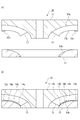
- the cover-side blade edge 13b is curved, it is not easy to dispose a sheet-like brazing material having a thickness of 100 ⁇ m or more on the cover-side blade edge 13b without a gap. Therefore, in the present embodiment, as shown in FIG. 3, brazing material pieces 14a to 14c divided into a plurality of pieces in the longitudinal direction are used. If the brazing filler metal pieces 14a to 14c are divided in this way, even if the cover-side blade edge 13b is curved, it can be disposed without any gap on the cover-side blade edge 13b.
- the thickness of the brazing filler metal pieces 14a to 14c is preferably slightly larger than the protruding height (thickness) of the spacer 13c. By doing so, pressure is applied to the brazing filler metal pieces 14a to 14c at the time of brazing, and the brazing filler metal can be spread over the joint portion without leakage.
- auxiliary brazing material (second brazing material) 15 is provided at a location corresponding to the joint between the adjacent brazing filler metal piece 14a and the brazing filler metal piece 14b and the joint between the brazing filler metal piece 14b and the brazing filler metal piece 14c. This is because when the brazing material is insufficient at the joint portion, the shortage is compensated for and the brazing is more reliably performed.
- a brazing material (third brazing material) 16 is provided and brazed to form a fillet at the joint portion after brazing.
- the brazing material 16 is disposed on both sides of the blade 13 in the vicinity of the cover-side blade edge 13 b.
- the brazing filler metal pieces 14a to 14c and the brazing filler metals 15 and 16 are fixed at predetermined positions of the blade 13 by means such as spot welding.
- a fillet means the brazing part protruded from the brazing joint joint surface.
- the disk 11 on which the brazing filler metal pieces 14a and the like are arranged is overlapped with a separately produced cover 12 as shown in FIG. 2 (b).
- the disk 11 has a cover-side blade edge (first joint surface) 13b facing downward, and the cover 12 has a blade mounting surface (second joint surface) 12a facing upward.
- the disk 11 and the cover 12 are brazed to be heated at a temperature corresponding to the melting temperature of the brazing material for a necessary time and further cooled. Join.
- the fixing jig 20 includes a first fixing member 21 for positioning the disk 11 and the cover 12, a second fixing member 26 disposed on the back surface 11b side of the disk 11 so as to face the first fixing member 21, and a first fixing member. 21 and a fastening shaft 28 for fastening the second fixing member 26.
- the first fixing member 21 includes a disk-shaped main body 22, a first restraining portion 23, and a second restraining portion 24.
- a hole 22 a through which the fastening shaft 28 passes is formed at the center of the main body 22.
- the first restraining portion 23 is a ring-shaped protrusion that continues in the circumferential direction of the main body 22, and is provided on one surface side of the main body 22.
- the second restraint portion 24 is provided on the inner side than the first restraint portion 23.
- the second constraining portion 24 is a hollow cylindrical projection having a space at a portion where the hole 22a of the main body 22 communicates.
- the first restraining part 23 and the second restraining part 24 are arranged on the same axis.
- the second fixing member 26 is a disk-like member, and a hole 26a through which the fastening shaft 28 passes is formed.
- the first fixing member 21 is disposed so as to contact the surface of the tip 112 a of the disk 11.
- the first restraining portion 23 is fitted into the inner periphery of the cover 12. Therefore, the diameter of the outer peripheral surface 23O of the first restraining portion 23 is set in consideration of the diameter of the inner peripheral surface 12I of the cover 12.
- the second restraining portion 24 is fitted into the shaft hole 111 of the disk 11. Therefore, the diameter of the outer peripheral surface 24O of the second restricting portion 24 is set in consideration of the diameter of the shaft hole 111.
- the second fixing member 26 is disposed so as to contact the back surface 11 b of the disk 11.
- the fastening shaft 28 is disposed so as to penetrate the hole 22a of the first fixing member 21 and the hole 26a of the second fixing member 26.
- the fastening shaft 28 is threaded (not shown) at the portion protruding from the first fixing member 21 and the portion protruding from the second fixing member 26, and the bolt B is screwed into this thread.
- the disk 11 and the cover 12 sandwiched between the first fixing member 21 and the second fixing member 26 are pressed against each other with a necessary force.
- the first restraining portion 23 provided in the main body 22 is fitted into the inner periphery of the cover 12, and the second restraining portion 24 provided in the main body 22 is fitted into the shaft hole 111 of the disc 11. 11 and the cover 12 are positioned in the radial direction.
- the fixing jig 20 is removed and finishing is performed.
- the finishing process the flat outer surface of the cover 12 is curved as shown in FIG. 5B with respect to the impeller 10 after brazing shown in FIG. 5A.
- Another finishing process is to remove a predetermined range from the outer periphery of the impeller 10 (disk 11, cover 12) as shown in FIG. As described above, this processing is performed to ensure dimensional accuracy and remove distortion.
- the spacer 13c is preferably removed by this processing. Since no brazing material is interposed between the spacer 13c and the blade mounting surface 12a of the cover 12, the joining of the portion becomes insufficient.
- the spacer 13c itself is not a necessary part for the impeller 10. Therefore, it is preferable from the viewpoint of securing the strength of the impeller 10 to remove the spacer 13c in accordance with the finishing process of cutting the outer periphery of the impeller 10 after the brazing is completed.
- Brazing material thickness 100 ⁇ m, 200 ⁇ m, 300 ⁇ m
- the energy absorbed by Charpy at the joint portion of the sample obtained by brazing under the above conditions was determined.
- the result is shown in FIG.
- the horizontal axis represents the brazing joint layer thickness
- the vertical axis represents the absorbed energy.
- the thickness of the brazing material is 100 ⁇ m. Since the brazing material flowed out of the joining surface during the brazing process, the thickness of the brazing layer was reduced to half that of the brazing material.
- the spacer 13c by providing the spacer 13c, the distance between the cover-side blade edge 13b (first joint surface) and the blade attachment surface 12a (second joint surface) is the most suitable for brazing. Can be held in. Accordingly, it is possible to prevent the brazing material from excessively flowing out between the cover side blade edge portion 13b and the blade mounting surface 12a, so that the brazing joint layer having a required thickness can be obtained while eliminating the waste of the brazing material. Thickness can be ensured.
- the spacer 13c since the spacer 13c is provided on the outer peripheral side to be removed after brazing from the beginning, it is not necessary to add a new process for removing the spacer 13c.
- the spacer 13c has been described as being provided integrally with the blade 13 formed integrally with the disk 11, but the present invention is not limited to this embodiment.
- the spacer can be manufactured separately from the constituent members of the impeller 10 such as the disk 11 and the cover 12. Further, when the blade 13 is formed integrally with the disk 11, a spacer can be provided integrally on the cover 12 side. Further, when the blade 13 is formed integrally with the cover 12, a spacer can be formed integrally with the blade 13, or a spacer can be formed integrally with the disk 11 side.
- the shape, size, etc. of the disk 11, the cover 12, and the blade 13 are examples, and other shapes can be employed.
Landscapes
- Engineering & Computer Science (AREA)
- Mechanical Engineering (AREA)
- General Engineering & Computer Science (AREA)
- Structures Of Non-Positive Displacement Pumps (AREA)
Abstract
Description
このインペラの製造方法として、別々に作製されたディスクとカバーを接合する方法が知られている。この場合、ブレードはディスク及びカバーのいずれかと一体的に形成されることが多い。ディスクとカバーの接合方法としては、溶接又はろう付けが選択される。ところが、溶接による接合では、溶接トーチを流路内に挿入する必要があるものの、流路が狭いと溶接トーチを流路内に挿入することが困難となり、溶接欠陥が生じやすくなることが指摘されている。これに対して、ろう付けによる接合では、例えばブレード付きのカバーとディスクとを接合する際に、その接合面にろう材を配置し、カバーとディスクを重ねて加熱炉に挿入し接合するものであるから、流路が狭い場合であっても容易に施工ができる。
本発明は、このような課題に基づいてなされたもので、ろう材の無駄を省きながらも、必要な厚さのろう材層を確保するのが容易なインペラの製造方法を提供することを目的とする。
本発明が対象とするインペラは、ディスクと、ディスクに対向配置されるカバーと、ディスクとカバーとの間に設けられる複数のブレードと、を備える。このインペラには、ディスクとカバーの間に流路が形成される。
本発明は、ディスク及びカバーを個別に作製する工程Xを備えている。ディスク及びカバーのいずれか一方にはブレードが一体的に形成されている。
本発明は次の工程として、ブレードに設けられる第1接合面とディスク及びカバーのいずれか一方に設けられる第2接合面との間に第1ろう材を介在させた状態で、ディスクとカバーとをろう付けにより接合する工程Yを備えている。
本発明は、工程Yにおいて、第1接合面と第2接合面の間隔を保持するスペーサをその外周側に設けて、ろう付けすることを特徴とする。このスペーサの厚さは、溶融前のろう材よりも薄いことが好ましい。
第1形態は、ディスク及びカバーとは別体としてスペーサを作製するものである。この場合、スペーサは第1接合面と第2接合面で挟み込むことになる。
第2形態は、スペーサを、ブレードと一体的に形成するか、または、ディスク及びカバーのいずれか一方に一体的に形成するものである。例えば、ブレードがディスクと一体的に作製されている場合には、スペーサをブレードに一体的に形成するか、または、スペーサをカバーに一体的に形成する。
第2形態は、ディスク又はカバーを作製する際にスペーサを一体的に形成すれば、その後にスペーサを第1接合面と第2接合面の間に配置する作業を省くことができるので、第1形態に比べて製造工程を簡易にできる利点がある。
ここで、スペーサと第1接合面または第2接合面との間にはろう材を設けないでろう付けが行われる。したがって、スペーサと第1接合面または第2接合面との間の接合は不十分である。そこで本発明において、ろう付けが完了した後に、インペラの外周側の所定の範囲を切削などによりスペーサを除去することが、インペラの強度の観点から好ましい。
本実施の形態により製造されるインペラ10は、回転軸に組み付けられる回転体として、遠心圧縮機などの回転機械に搭載されるものである。
インペラ10は、図1に示すように、ディスク11と、カバー12と、複数の羽根形状のブレード13とを主たる構成要素として備えている。
ディスク11は、図示しない回転軸に同軸に取り付けられる略円盤状の部材である。
ブレード13は、ディスク11に一端(図1では下側)が接するとともに前記回転軸の回転軸線Cを中心に放射状に複数配設されている。なお、この実施の形態において、ブレード13は、ディスク11の素材を削り出すことによりディスク11と一体的に形成されているものとするが、カバー12と一体的に形成することもできる。
カバー12は、ディスク11と対向配置される。また、カバー12は、ブレード13の他端(図1では上側)と接する。そして、ブレード13の側面と、ディスク11及びカバー12が互いに対向する面との間に形成される空間は、本圧縮機で圧縮する気体の流路Rとして機能する。
なお、本実施の形態において、回転軸線Cに近い側がインペラ10における内周側であり、遠い側が外周側である。また、図1において、圧縮される気体は流路R内を矢印Eの向きに流れる。さらに、インペラ10の回転軸線Cの方向をY方向とし、同じく径方向をX方向とする。
そして、上述したように互いに隣接するブレード13、13同士のそれぞれの間には、インペラ10の回転に伴って圧縮空気を生成するための流路Rが形成されており、その流路Rは、ディスク11、ブレード13、及びカバー12の形状に従って、径方向X及び回転軸方向Yに湾曲した形状となっている。
先ず、図2(a)に示すように、ディスク11を複数のブレード13、13、…とともに素材より削り出して一体的に形成する。この一体成形の際に、カバー側ブレード縁部13bにスペーサ13cを形成する。スペーサ13cは、カバー側ブレード縁部13bからカバー12に向けて突出する。また、スペーサ13cは、ブレード13の外周側に設けられている。スペーサ13cの突出高さは、後述するように、ろう材の厚みに応じて定められる。
スペーサ13cは、全てのブレード13に設けてもよいが、ディスク11を平面視した場合に、三角形の頂点に対応するように少なくとも3つのブレード13に設ける、あるいは、1つおきに設ける、ことがスペーサ13cの形成工数を減らす上で好ましい。なお、図2は、図1とはディスク11及びカバー12を上下反転して示しているが、特許文献1と同様に、ろう付けはこの上下の向きで行う。
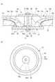
固定冶具20は、ディスク11とカバー12の位置決め担う第1固定部材21と、第1固定部材21と対向してディスク11の裏面11b側に配置される第2固定部材26と、第1固定部材21と第2固定部材26を締結するための締結軸28と、を備えている。
本体22の中心部には、締結軸28が貫通する孔22aが形成されている。第1拘束部23は、本体22の円周方向に連なるリング状の突起であり、本体22の一方の面側に設けられる。第2拘束部24は、第1拘束部23よりも内側に設けられる。第2拘束部24は、本体22の孔22aが連通する部分を空間とする中空円筒状の突起である。第1拘束部23と第2拘束部24は、同軸上に配置されている。
第2固定部材26は、円盤状の部材であり、締結軸28が貫通する孔26aが形成されている。
第1拘束部23がカバー12の内周に嵌入される。そのために、第1拘束部23の外周面23Oの径は、カバー12の内周面12Iの径を考慮して設定される。また、第1固定部材21は、第2拘束部24がディスク11の軸孔111に嵌入される。そのために、第2拘束部24の外周面24Oの径は、軸孔111の径を考慮して設定される。
一方、第2固定部材26は、ディスク11の裏面11bに接するように配置される。そして、第1固定部材21の孔22aと第2固定部材26の孔26aを貫通するように締結軸28を配置させる。締結軸28は、第1固定部材21から突出する部分及び第2固定部材26から突出する部分はねじ山が切られており(図示を省略)、このねじ山にボルトBをねじ込む。ねじ込み量を調整することで、第1固定部材21と第2固定部材26の間に挟まれるディスク11とカバー12を相互に必要な力で押し付ける。このとき、本体22に設けられる第1拘束部23がカバー12の内周に嵌入され、また、本体22に設けられる第2拘束部24がディスク11の軸孔111に嵌入されることで、ディスク11とカバー12の径方向の位置決めがなされる。
仕上げ加工としては、図5(a)に示すろう付け終了後のインペラ10に対して、図5(b)に示すようにカバー12の平坦な外表面を湾曲な面にすることが掲げられる。また、他の仕上げ加工としては、図5(b)に示すようにインペラ10(ディスク11、カバー12)の外周から所定範囲を除去することが掲げられる。この加工は、前述したように、寸法精度確保及び歪除去のために行われる。そしてこの加工により、スペーサ13cを除去することが好ましい。スペーサ13cとカバー12のブレード取付け面12aの間にはろう材が介在していないので、当該部分の接合は不十分になる。また、スペーサ13c自体はインペラ10として必要な部分ではない。そこで、ろう付けが終了した後に、インペラ10の外周を切削する仕上げ加工に伴って、スペーサ13cを除去することが、インペラ10の強度確保の観点から好ましい。
以下、本発明の効果を確認するために行った実験例を説明する。
SUS630からなる2つの鋼片を突き合わせて金ろう材でろう付けしてシャルピ衝撃試験用の試験片(JIS Z2242準拠)を作製した。用いた鋼片の化学組成、ろう材の組成を下記する。なお、ろう材は下記厚さのシート状のものを用い、当初の厚さが保持されるように2つの鋼片の間にスペーサを設けてろう付けの熱処理を行った。ただし、ろう材厚さが100μmのものは、スペーサを設けることなくろう付けを行った。
Cr;15.5%、Ni;4.3%、Cu;3.5%、Nb+Ta;0.35%
C;0.05% Si;0.25%、 Mn;0.8%、P;0.0035%、S;0.007%
残部;Feおよび不可避不純物
ろう材の組成:18%Ni-82%Au
図6は横軸にろう接合層厚み、縦軸に吸収エネルギを示している。ろう接合層が50μmの例は、ろう材の厚さが100μmのものである。ろう付けの過程でろう材が接合面から流出したために、ろう接合層の厚さはろう材の半分まで減少した。
ろう接合層とシャルピ吸収エネルギの関係について観ると、厚さが50μmでは5J以下のシャルピ吸収エネルギしか得られないのに対して、厚さが200μmになると15J程度となり、厚さが300μmになると20J以上のシャルピ吸収エネルギが得られる。
特に本実施の形態は、もともとろう付けした後に除去する外周側にスペーサ13cを設けているので、スペーサ13cを除去するための工程を新たに加える必要がない。
特に、スペーサ13cについては、ディスク11に一体的に形成されたブレード13に一体的に設ける例を示したが、本発明はこの形態に限定されない。スペーサをディスク11、カバー12などのインペラ10の構成部材とは別体として作製することができる。また、ディスク11にブレード13を一体的に形成した場合に、カバー12側にスペーサを一体的に設けることもできる。さらに、カバー12にブレード13を一体的に形成した場合に、ブレード13にスペーサを一体的に形成できるし、ディスク11側にスペーサを一体的に形成することもできる。
11…ディスク
12…カバー、12a…ブレード取付け面(第2接合面)
13…ブレード、13a…ディスク側ブレード縁部(第1接合面)、13c…スペーサ
14、15、16…ろう材、14a,14b,14c…ろう材片
20…固定冶具、21…第1固定部材、23…第1拘束部、24…第2拘束部
R…流路
Claims (8)
- ディスクと、前記ディスクに対向配置されるカバーと、前記ディスクと前記カバーとの間に設けられる複数のブレードと、を備え、前記ディスクと前記カバーの間に流路が形成されるインペラの製造方法であって、
いずれか一方に前記ブレードが一体的に形成された前記ディスク又は前記カバーを個別に作製する工程Xと、
前記ブレードに設けられる第1接合面と前記ディスク及び前記カバーのいずれか一方に設けられる第2接合面との間に第1ろう材を介在させた状態で、前記ディスクと前記カバーとをろう付けにより接合する工程Yと、
を備え、
前記工程Yにおいて、
前記第1接合面と前記第2接合面の間隔を保持するスペーサを前記インペラの外周側に設けて、ろう付けすることを特徴とするインペラの製造方法。 - 前記スペーサは、前記ブレードと一体的に形成するか、または、前記ディスク及び前記カバーのいずれか一方に一体的に形成する、
請求項1に記載のインペラの製造方法。 - ろう付けが完了した後に、前記インペラの外周側の所定の範囲を除去する、
請求項1又は2に記載のインペラの製造方法。 - 前記スペーサを除去するように前記インペラの外周側の所定の範囲を除去する、
請求項3に記載のインペラの製造方法。 - 前記工程Yにおいて、
ろう付け前に、前記第1ろう材を、長手方向に複数に分割されたろう材片として前記第1接合面と前記第2接合面の間に介在させる、
請求項1に記載のインペラの製造方法。 - 前記工程Yにおいて、
隣接する前記ろう材片の継ぎ目に対応する箇所に第2ろう材を設ける、
請求項5に記載のインペラの製造方法。 - 前記工程Yにおいて、
前記ディスクと前記カバーを冶具により軸方向に圧力を付与した状態でろう付けを行い、
前記冶具は、
前記カバーの内径に接して前記カバーの径方向への移動を拘束する第1拘束部と、前記ディスクの内径に接して前記ディスクの径方向への移動を拘束する第2拘束部と、を同軸上に備える、
請求項1に記載のインペラの製造方法。 - 前記スペーサの厚さは、溶融前の前記第1ろう材よりも薄い、
請求項1に記載のインペラの製造方法。
Priority Applications (3)
| Application Number | Priority Date | Filing Date | Title |
|---|---|---|---|
| EP11794614.5A EP2639460A4 (en) | 2010-11-11 | 2011-01-28 | Method for manufacturing impeller |
| CN201180002662.7A CN102625881B (zh) | 2010-11-11 | 2011-01-28 | 叶轮的制造方法 |
| US13/379,710 US8650754B2 (en) | 2010-11-11 | 2011-01-28 | Method for manufacturing impeller |
Applications Claiming Priority (2)
| Application Number | Priority Date | Filing Date | Title |
|---|---|---|---|
| JP2010252434A JP5535878B2 (ja) | 2010-11-11 | 2010-11-11 | インペラの製造方法 |
| JP2010-252434 | 2010-11-11 |
Publications (1)
| Publication Number | Publication Date |
|---|---|
| WO2012063375A1 true WO2012063375A1 (ja) | 2012-05-18 |
Family
ID=46050550
Family Applications (1)
| Application Number | Title | Priority Date | Filing Date |
|---|---|---|---|
| PCT/JP2011/000484 Ceased WO2012063375A1 (ja) | 2010-11-11 | 2011-01-28 | インペラの製造方法 |
Country Status (4)
| Country | Link |
|---|---|
| EP (1) | EP2639460A4 (ja) |
| JP (1) | JP5535878B2 (ja) |
| CN (1) | CN102625881B (ja) |
| WO (1) | WO2012063375A1 (ja) |
Cited By (2)
| Publication number | Priority date | Publication date | Assignee | Title |
|---|---|---|---|---|
| US11297989B2 (en) * | 2016-09-01 | 2022-04-12 | Samsung Electronics Co., Ltd. | Cleaner |
| US20240424587A1 (en) * | 2021-03-05 | 2024-12-26 | Danfoss A/S | Techniques for applying brazing material to form a shrouded impeller |
Families Citing this family (6)
| Publication number | Priority date | Publication date | Assignee | Title |
|---|---|---|---|---|
| KR102126867B1 (ko) * | 2013-09-24 | 2020-06-25 | 한화파워시스템 주식회사 | 임펠러 어셈블리 및 임펠러 어셈블리 제작방법 |
| CN104279186A (zh) * | 2014-09-17 | 2015-01-14 | 杭州杭氧透平机械有限公司 | 一种大流量超大直径半铣半焊闭式三元叶轮及制造方法 |
| CN105269278B (zh) * | 2015-11-19 | 2019-02-19 | 湖北双剑鼓风机股份有限公司 | 一种三元流叶轮的加工方法 |
| JP7149174B2 (ja) | 2018-12-10 | 2022-10-06 | ダイキン工業株式会社 | クローズドインペラ及びその製造方法 |
| WO2021030440A1 (en) * | 2019-08-13 | 2021-02-18 | Emerson Climate Technologies, Inc. | Methods for manufacturing a shrouded impeller, shrouded impeller and compressor |
| CN113927113B (zh) * | 2021-09-23 | 2023-03-21 | 贵州永红航空机械有限责任公司 | 用于闭式叶轮钎焊的钎料及钎焊装配方法 |
Citations (3)
| Publication number | Priority date | Publication date | Assignee | Title |
|---|---|---|---|---|
| JPH07109997A (ja) * | 1993-10-14 | 1995-04-25 | Mitsubishi Heavy Ind Ltd | 流体機械用インペラ及びその製造方法 |
| JP2005146962A (ja) * | 2003-11-14 | 2005-06-09 | Hitachi Industries Co Ltd | 遠心羽根車およびその製造方法 |
| JP2010174652A (ja) | 2009-01-27 | 2010-08-12 | Mitsubishi Heavy Ind Ltd | インペラの製造方法およびインペラ |
Family Cites Families (6)
| Publication number | Priority date | Publication date | Assignee | Title |
|---|---|---|---|---|
| US2402204A (en) * | 1941-11-19 | 1946-06-18 | Northrop Aireraft Inc | Apparatus for assembling centrifugal impellers |
| US2654943A (en) * | 1949-08-30 | 1953-10-13 | Allis Chalmers Mfg Co | Method for the manufacture of impellers and the like |
| PL164401B1 (pl) * | 1991-02-01 | 1994-07-29 | Politechnika Lodzka | Sposób wytwarzania wirnika sprężarki przepływowej |
| JPH07224789A (ja) * | 1994-02-10 | 1995-08-22 | Toto Ltd | 薄肉板多層積層体及びこれを構成する薄肉環状円板の成形型 |
| JP2002180993A (ja) * | 2000-12-12 | 2002-06-26 | Matsushita Electric Ind Co Ltd | 自吸式ポンプ |
| JP2010180721A (ja) * | 2009-02-03 | 2010-08-19 | Mitsubishi Heavy Ind Ltd | インペラの製造方法および圧縮機 |
-
2010
- 2010-11-11 JP JP2010252434A patent/JP5535878B2/ja not_active Expired - Fee Related
-
2011
- 2011-01-28 EP EP11794614.5A patent/EP2639460A4/en not_active Withdrawn
- 2011-01-28 CN CN201180002662.7A patent/CN102625881B/zh not_active Expired - Fee Related
- 2011-01-28 WO PCT/JP2011/000484 patent/WO2012063375A1/ja not_active Ceased
Patent Citations (3)
| Publication number | Priority date | Publication date | Assignee | Title |
|---|---|---|---|---|
| JPH07109997A (ja) * | 1993-10-14 | 1995-04-25 | Mitsubishi Heavy Ind Ltd | 流体機械用インペラ及びその製造方法 |
| JP2005146962A (ja) * | 2003-11-14 | 2005-06-09 | Hitachi Industries Co Ltd | 遠心羽根車およびその製造方法 |
| JP2010174652A (ja) | 2009-01-27 | 2010-08-12 | Mitsubishi Heavy Ind Ltd | インペラの製造方法およびインペラ |
Non-Patent Citations (1)
| Title |
|---|
| See also references of EP2639460A4 * |
Cited By (5)
| Publication number | Priority date | Publication date | Assignee | Title |
|---|---|---|---|---|
| US11297989B2 (en) * | 2016-09-01 | 2022-04-12 | Samsung Electronics Co., Ltd. | Cleaner |
| US20220183522A1 (en) * | 2016-09-01 | 2022-06-16 | Samsung Electronics Co., Ltd. | Cleaner |
| US12075965B2 (en) | 2016-09-01 | 2024-09-03 | Samsung Electronics Co., Ltd. | Cleaner |
| US20240424587A1 (en) * | 2021-03-05 | 2024-12-26 | Danfoss A/S | Techniques for applying brazing material to form a shrouded impeller |
| US12370615B2 (en) * | 2021-03-05 | 2025-07-29 | Danfoss A/S | Techniques for applying brazing material to form a shrouded impeller |
Also Published As
| Publication number | Publication date |
|---|---|
| EP2639460A1 (en) | 2013-09-18 |
| JP5535878B2 (ja) | 2014-07-02 |
| CN102625881A (zh) | 2012-08-01 |
| JP2012102678A (ja) | 2012-05-31 |
| CN102625881B (zh) | 2015-04-01 |
| EP2639460A4 (en) | 2017-10-18 |
Similar Documents
| Publication | Publication Date | Title |
|---|---|---|
| JP5535878B2 (ja) | インペラの製造方法 | |
| JP4699531B2 (ja) | インペラの製造方法およびインペラ | |
| US8146795B2 (en) | Method of friction welding | |
| JP2010180721A (ja) | インペラの製造方法および圧縮機 | |
| KR101570139B1 (ko) | 터보기계의 로터 샤프트, 및 터보기계의 로터의 제조 방법 | |
| EP2281653B1 (en) | A method of friction welding a first workpiece to a second workpiece with converging parts | |
| US11879476B2 (en) | Closed impeller and method for producing closed impeller | |
| JPH021961B2 (ja) | ||
| US8650754B2 (en) | Method for manufacturing impeller | |
| KR102208490B1 (ko) | 회전 기계의 회전부 제조 방법 | |
| JP2009092064A (ja) | ディスクロータ及びその製造方法 | |
| JP5490076B2 (ja) | 摩擦攪拌接合方法、摩擦攪拌接合物、及び摩擦攪拌接合工具 | |
| US9476304B2 (en) | Laser casting blade repair | |
| EP1450984B1 (en) | A method for manufacturing a stator or rotor component | |
| KR101444849B1 (ko) | 회전 기계의 회전부 제조 방법 | |
| CA2512126C (en) | Split francis turbine runner | |
| US10989345B2 (en) | Process for brazing an accessory on a tube, and corresponding assembly | |
| JP2009275513A (ja) | 羽根車、羽根車を用いた圧縮機、および羽根車の製造方法 | |
| KR101612854B1 (ko) | 유체 회전 기계의 임펠러 조립체 | |
| CN110621868B (zh) | 内燃机用活塞及其制造方法 | |
| JP4959744B2 (ja) | 蒸気タービン用タービンロータ及び蒸気タービン | |
| JP2016156333A (ja) | 溶接装置及び溶接継手 |
Legal Events
| Date | Code | Title | Description |
|---|---|---|---|
| WWE | Wipo information: entry into national phase |
Ref document number: 201180002662.7 Country of ref document: CN |
|
| WWE | Wipo information: entry into national phase |
Ref document number: 2752/MUMNP/2011 Country of ref document: IN |
|
| REEP | Request for entry into the european phase |
Ref document number: 2011794614 Country of ref document: EP |
|
| WWE | Wipo information: entry into national phase |
Ref document number: 2011794614 Country of ref document: EP |
|
| WWE | Wipo information: entry into national phase |
Ref document number: 13379710 Country of ref document: US |
|
| 121 | Ep: the epo has been informed by wipo that ep was designated in this application |
Ref document number: 11794614 Country of ref document: EP Kind code of ref document: A1 |
|
| NENP | Non-entry into the national phase |
Ref country code: DE |