WO2012063384A1 - テンションバランサ - Google Patents
テンションバランサ Download PDFInfo
- Publication number
- WO2012063384A1 WO2012063384A1 PCT/JP2011/004392 JP2011004392W WO2012063384A1 WO 2012063384 A1 WO2012063384 A1 WO 2012063384A1 JP 2011004392 W JP2011004392 W JP 2011004392W WO 2012063384 A1 WO2012063384 A1 WO 2012063384A1
- Authority
- WO
- WIPO (PCT)
- Prior art keywords
- outer casing
- inner movable
- tension balancer
- tension
- rod
- Prior art date
- Legal status (The legal status is an assumption and is not a legal conclusion. Google has not performed a legal analysis and makes no representation as to the accuracy of the status listed.)
- Ceased
Links
Images



Classifications
-
- B—PERFORMING OPERATIONS; TRANSPORTING
- B60—VEHICLES IN GENERAL
- B60M—POWER SUPPLY LINES, AND DEVICES ALONG RAILS, FOR ELECTRICALLY- PROPELLED VEHICLES
- B60M1/00—Power supply lines for contact with collector on vehicle
- B60M1/12—Trolley lines; Accessories therefor
- B60M1/26—Compensation means for variation in length
-
- B—PERFORMING OPERATIONS; TRANSPORTING
- B60—VEHICLES IN GENERAL
- B60M—POWER SUPPLY LINES, AND DEVICES ALONG RAILS, FOR ELECTRICALLY- PROPELLED VEHICLES
- B60M1/00—Power supply lines for contact with collector on vehicle
- B60M1/12—Trolley lines; Accessories therefor
- B60M1/20—Arrangements for supporting or suspending trolley wires, e.g. from buildings
-
- B—PERFORMING OPERATIONS; TRANSPORTING
- B60—VEHICLES IN GENERAL
- B60M—POWER SUPPLY LINES, AND DEVICES ALONG RAILS, FOR ELECTRICALLY- PROPELLED VEHICLES
- B60M1/00—Power supply lines for contact with collector on vehicle
- B60M1/12—Trolley lines; Accessories therefor
- B60M1/20—Arrangements for supporting or suspending trolley wires, e.g. from buildings
- B60M1/225—Arrangements for fixing trolley wires to supporting-lines which are under tension
Definitions
- Embodiment of this invention is related with the tension balancer which maintains the tension
- the train receives power supply from the train line through a current collector such as a pantograph.
- a tension balancer for maintaining the tension of the train line is interposed between the support column and the train line.
- the conventional tension balancer 101 includes a spring case 120, a link rod 132, a coil spring 140, a rotating arm 168, a frame 190, and the like (see, for example, Patent Document 1).
- the spring case 120 extends in the vertical direction along with the support column 103, and is fixed to the support column 103 by a fixed band 103a.
- the link rod 132 is inserted from the inside of the spring case 120 through the rod insertion hole 126 a formed in the lid portion 126 and extends to the outside of the spring case 120.
- the lower end of the link rod 132 is rotatably connected to the spring receiving portion 134, and the upper end of the link rod 132 is connected to the rotating arm 168.
- a coil spring 140 is accommodated in the spring case 120.
- the coil spring 140 is sandwiched between the lid portion 126 and the spring receiving portion 134 and stored in a compressed state.
- the frame 190 is fixed to the upper end of the spring case 120.
- the frame 190 is fixed to the support column 103 by a fixed band 103b.
- the rotating arm 168 is formed of a plate formed in a substantially L shape. A corner of the rotating arm 168 is pivotally supported with respect to the frame 190, one end is connected to the upper end of the link rod 132, and the other end is connected to the train line 102.
- the tension balancer 101 urges the link rod 132 into the spring case 120 by the elastic force of the coil spring 140, and is applied to the train line 102 via a pivot arm 168 that is pivotally supported. An almost constant tension is applied.
- the spring receiving part 134 cannot slide smoothly in the spring case 120, and the function of the tension balancer 101 may be deteriorated or noise may be generated.
- a force deviating from the axial direction is applied to the coil spring 140, which may reduce the durability of the coil spring 140.
- the present invention has been made to solve the above-described problems, and an object of the present invention is to provide a tension balancer with good functions and quality.
- a tension balancer is a tension balancer that is interposed between an overhead wire and a support and maintains the tension of the overhead wire, and is formed in a cylindrical shape.
- An outer casing provided with a lower end pivotally supported by a support column and capable of being inverted, and projecting from the upper end of the outer casing through the outer casing and provided so as to be able to appear and retract in the axial direction of the outer casing.
- An inner movable part a coil spring housed in the outer casing and urging the inner movable part in the immersion direction, a fulcrum pivotally supported by a support, and a movable part connected to the upper end of the inner movable part It has an overhead line connection point to which a connection point and an overhead line are connected, and a rotation connection part provided to be rotatable around the fulcrum.
- the tension balancer is a tension balancer that is interposed between the overhead wire and the support column to maintain the tension of the overhead wire, and includes an outer casing formed in a cylindrical shape, An inner movable portion that is inserted through the outer casing and protrudes from the lower end of the outer casing, and the lower end is pivotally supported by a support column and can be inverted, and can be projected and retracted in the axial direction of the outer casing; A coil spring housed in the outer casing and biasing the inner movable section in the immersion direction, a fulcrum pivotally supported by the column, a movable section coupling point to which the upper end of the outer casing is coupled, and an overhead wire And a rotating connecting portion provided to be rotatable about the fulcrum.
- a tension balancer with good function and quality can be provided.
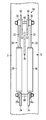
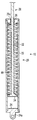
- FIG. 2 is a cross-sectional view taken along the line II-II in FIG. It is a longitudinal cross-sectional view of the balancer main body of the tension balancer which concerns on the 1st Embodiment of this invention. It is an elevation view which shows the attachment state of the tension balancer which concerns on the 2nd Embodiment of this invention. It is an elevation view which shows the attachment state of the tension balancer which concerns on the 3rd Embodiment of this invention. It is a longitudinal cross-sectional view of the balancer main body of the tension balancer which concerns on the 4th Embodiment of this invention. It is an elevation which shows the attachment state of the conventional tension balancer.
- FIG. 1 is an elevational view showing a tension balancer attached state.
- 2 is a cross-sectional view taken along the line II-II in FIG.
- FIG. 3 is a longitudinal sectional view of the balancer body.
- the tension balancer 1 is a tension balancer 1 for train lines.
- the tension balancer 1 is interposed between the support body such as the column 3 and the train line 2 to keep the tension of the train line 2 constant.
- the tension balancer 1 includes two balancer bodies 10 arranged in parallel to each other and two sets of rotation connecting portions 60.
- Each balancer main body 10 includes an outer casing 20, an inner movable portion 30, and a coil spring 40 as shown in FIG.
- the outer housing 20 includes a cylindrical portion 22, a first lid portion 24, and a second lid portion 26 that are formed in a cylindrical shape.
- the first lid portion 24 closes the lower end of the cylindrical portion 22.
- the first lid portion 24 is integrally provided with a mounting plate 24a protruding from the lower surface thereof.
- a through hole is formed in the mounting plate 24a.
- the first support plate 3 a that protrudes in the direction in which the train line 2 extends is formed on the column 3.
- a through hole is formed in the two first support plates 3a.
- one stud bolt 80 is inserted into the through hole of the mounting plate 24a of the two outer casings 20 and the through hole of the two first support plates 3a, and the outer casing 20 is pivotally supported with respect to the support column 3 with the stud bolt 80 as a fulcrum.
- the second lid portion 26 closes the upper end of the cylindrical portion 22 and serves as a spring seat for the coil spring 40.
- the second lid part 26 is formed with a rod insertion hole 26a through which a rod part 32 of the inner movable part 30 described later is inserted.
- the inner movable portion 30 is provided so as to be inserted in the outer casing 20, protrude from the upper end of the outer casing 20, and protrude and retract in the axial direction of the outer casing 20.
- the inner movable portion 30 has a rod portion 32, a spring receiving portion 34, and an attachment portion 36.
- the rod portion 32 is formed in a rod shape and extends to the axial center of the outer casing 20.
- the rod portion 32 is inserted from the inside of the outer housing 20 through the rod insertion hole 26 a of the second lid portion 26 and protrudes from the upper end of the outer housing 20.
- the spring receiving portion 34 is fixed to the lower end of the rod portion 32 and serves as a spring seat for the coil spring 40.
- the attachment portion 36 is provided at the upper end of the rod portion 32.
- the coil spring 40 is housed in the outer casing 20.
- the coil spring 40 extends spirally along the axial direction of the outer casing 20.
- the coil spring 40 is sandwiched between the second lid portion 26 of the outer casing 20 and the spring receiving portion 34 of the inner movable portion 30, and is stored in a compressed state. That is, the coil spring 40 biases the inner movable portion 30 in a direction to be immersed in the outer casing 20.
- the set of rotation connecting portions 60 includes three long plates (a first long plate 62, a second long plate 64, and a third long plate 66). Through holes are formed in both end portions of the three long plates 62, 64, 66, respectively.
- the second end of the first long plate 62 and the first end of the second long plate 64, the second end of the second long plate 64, the first end of the third long plate 66, and the third long plate 66 By inserting stud bolts 82, 84, 86, which will be described later, into the second end and the first end of the first long plate 62, the three long plates 62, 64, 66 are assembled in a triangular shape. It is rare.
- the post 3 is formed with a single second support plate 3b protruding in the direction in which the train line 2 extends.
- the second support plate 3b is formed at a higher position than the first support plate 3a.
- a through hole is formed in the second support plate 3b.
- one stud is provided in the through hole of the first long plate 62, the through hole of the second long plate 64, and the through hole of the second support plate 3b of the two sets of the rotation connecting portions 60.
- the bolt 82 is inserted, and the rotation connecting portion 60 is pivotally supported with respect to the support column 3 with the stud bolt 82 as a fulcrum.
- One stud bolt is provided for the through hole of the mounting portion 36 of the two inner movable parts 30, the through hole of the first long plate 62 and the through hole of the third long plate 66 of the two sets of rotating connection parts 60. 84 is inserted and the inner side movable part 30 and the rotation connection part 60 are connected.
- a connecting tool 2 a is fixed to the end of the train line 2.
- a through hole is formed in the connection tool 2a.
- One stud bolt 86 is inserted into the through hole of the connection tool 2 a of the train line 2, the through hole of the second long plate 64 and the through hole of the third long plate 66 of the two sets of rotation connecting portions 60.
- the train line 2 and the inner movable part 30 are connected.
- the spring receiving part 134 cannot slide smoothly in the spring case 120, and the function of the tension balancer 101 may be deteriorated or noise may be generated. Further, a force deviating from the axial direction is applied to the coil spring 140, and the life of the coil spring 140 may be shortened.
- the mounting plate 24a of the outer casing 20 is pivotally supported by the first support plate 3a around the stud bolt 80, and the balancer body 10 can be rotated with respect to the column 3. Is attached. Therefore, when the connecting line 84 rotates about the fulcrum 82 and the connecting point 84 between the rotating connecting part 60 and the inner movable part 30 rotates due to the expansion and contraction of the train line 2, the balancer accordingly.
- the main body 10 rotates around the stud bolt 80.
- the inner movable unit 30 always moves along the axis of the outer casing 20.
- the spring receiving portion 34 can slide smoothly in the outer housing 20 as compared with the conventional tension balancer 101, and the function of the tension balancer 1 is exhibited. This makes it easy to generate abnormal noise due to sliding of the spring receiving portion 34. Furthermore, according to this embodiment, since the axial force is always applied to the coil spring 40, the durability of the coil spring 40 can be improved.
- the link rod 132 rotates around a connection point 138 with the spring receiving portion 134. Therefore, it is necessary to form a rod insertion hole 126 a having a sufficient size to allow the link rod 132 to rotate, in the lid portion 126 of the spring case 120. As a result, rainwater or the like easily enters the spring case 120 from the gap, and the coil spring 140 is likely to deteriorate.
- the diameter of the rod insertion hole 26a of the second lid portion 26 is set to the rod portion. It is sufficient to design the diameter slightly larger than the diameter of 32, and the gap between the rod portion 32 and the rod insertion hole 26a can be made as small as possible. Therefore, according to the tension balancer 1 according to the present embodiment, compared to the conventional tension balancer 101, rainwater or the like is less likely to enter the outer housing 20 through the gap, and the coil spring 40 is less likely to deteriorate.
- the coil spring 40 can be made smaller or the material of the coil spring 40 can be lowered, and the tension balancer 1 can be reduced in size and cost.
- FIG. 4 is an elevational view showing a tension balancer attached state.
- this embodiment is a modification of 1st Embodiment, the same code
- the balancer body 10 is attached upside down with respect to the first embodiment. Specifically, the mounting plate 24 a of the outer casing 20 is connected to the rotation connecting portion 60, and the mounting portion 36 of the inner movable portion 30 is pivotally supported by the first support plate 3 a of the support column 3.
- the rod insertion hole 26a of the second lid portion 26 is disposed below, rainwater or the like is generated from the gap between the rod portion 32 and the rod insertion hole 26a as compared with the first embodiment. It is difficult to enter the outer casing 20 and the coil spring 40 is unlikely to deteriorate.
- the elastic force of the coil spring 40 can be designed to be small. Therefore, the coil spring 40 can be made smaller or the material of the coil spring 40 can be lowered, and the tension balancer 1 can be reduced in size and cost.
- FIG. 5 is an elevation view showing a tension balancer attached state.
- this embodiment is a modification of 1st Embodiment, the same code
- the rotating arm 68 is made of a plate formed in an approximately L shape. A through hole is formed in each of the corner and both ends of the rotating arm 68.
- One stud bolt 82 is inserted into the through hole at the corner of the two rotating arms 68 and the through hole of the second support plate 3b.
- the rotating arm 68 has the stud bolt 82 as a fulcrum,
- the shaft 3 is pivotally supported so as to be rotatable.
- One stud bolt 84 is inserted into the through hole of the mounting portion 36 of the two inner movable parts 30 and the through hole of one end part of the two rotary arms 68, and the inner movable part 30 and the rotary arm are inserted.
- 68 is connected.
- One stud bolt 86 is inserted into the through hole of the connecting tool 2a of the train line 2 and the through hole at the other end of the two rotating arms 68, and the train line 2 and the rotating arm 68 are connected. Has been.
- FIG. 6 is a longitudinal sectional view of the balancer body.
- this embodiment is a modification of 1st Embodiment, the same code
- two coil springs 40 are arranged in series in the outer casing 20.
- An intermediate spring receiver 42 is disposed between the two coil springs 40.
- the two coil springs 40 are disposed so as to be reversely wound with each other.
- balancer bodies 10 are used, but one or more balancers may be used.
- 2 sets of rotation connection parts 60 were used, you may use 1 set or multiple sets.
- two coil springs 40 are arranged in series in the outer casing 20, but three or more coil springs 40 may be used.
- a plurality of coil springs 40 may be arranged in parallel in the outer housing 20.
- the train line 2 has been described as an example, but the present invention may be used for an overhead line other than the train line 2, for example, a power line.
Landscapes
- Engineering & Computer Science (AREA)
- Mechanical Engineering (AREA)
- Suspension Of Electric Lines Or Cables (AREA)
- Springs (AREA)
- Current-Collector Devices For Electrically Propelled Vehicles (AREA)
Abstract
テンションバランサ(1)は、電車線(2)と支柱(3)との間に介装されて、電車線(2)の張力を維持する。テンションバランサ(1)は、外側筒体(20)、内側可動部(30)、コイルばね、および、回動連結部(60)を備えている。筒状に形成された外側筐体(20)は、下端が支柱(3)に軸支され倒立可能に設けられている。内側可動部(30)は、外側筐体(20)内を挿通し、外側筐体(20)の上端から突出して、外側筐体の軸方向に出没可能に設けられている。コイルばね(40)は、外側筐体(20)内に収納されて、内側可動部(30)を没入方向に付勢する。回動連結部(60)は、支柱(3)に軸支される支点(82)、内側可動部(30)の上端が連結された可動部連結点(84)、および、電車線が連結される電車線連結点(86)を有し、支点(82)を中心に回動可能に設けられている。
Description
本発明の実施形態は、架空線の張力を維持するテンションバランサに関する。
電車は、パンタグラフなどの集電装置を介して電車線から電力供給を受ける。温度変化に伴う電車線の伸縮などにより電車線の張力が変化すると、電車線と集電装置との接触が悪化して、安定した電力供給が妨げられてしまう。そこで、支柱と電車線との間には、電車線の張力を維持するためのテンションバランサが介装されている。
従来のテンションバランサ101は、図7に示したように、ばねケース120、リンクロッド132、コイルばね140、回動アーム168、および、フレーム190などを備えている(例えば特許文献1参照)。
ばねケース120は、支柱103と並んで鉛直方向に延び、固定バンド103aにより支柱103に固定されている。リンクロッド132は、ばねケース120の内部から蓋部126に形成されたロッド挿通孔126aを挿通し、ばねケース120の外部に延びている。リンクロッド132の下端は、ばね受部134に回転可能に連結され、リンクロッド132の上端は、回動アーム168に連結されている。
ばねケース120の内部には、コイルばね140が収納されている。コイルばね140は、蓋部126とばね受部134との間に挟持され、圧縮された状態で収納されている。
フレーム190は、ばねケース120の上端に固定されている。フレーム190は、固定バンド103bにより支柱103に固定されている。回動アーム168は、略L字状に形成された板からなる。回動アーム168の角部は、フレーム190に対して軸支され、一端は、リンクロッド132の上端に連結され、他端は、電車線102に連結されている。
テンションバランサ101は、コイルばね140の弾性力によって、リンクロッド132をばねケース120内に没入させる方向に付勢し、回動可能に軸支された回動アーム168を介して、電車線102にほぼ一定の張力を付与する。
従来のテンションバランサ101では、電車線102の伸縮によって、回動アーム168が支点182を中心に回動すると、リンクロッド132は、ばね受部134との連結点138を中心に回動しながら、ばねケース120に対して出没方向に移動する。しかし、ばねケース120は、支柱103に固定されているため、リンクロッド132の軸方向とばねケース120の軸方向とが常に一致せず、リンクロッド132は、ばね受部134をばねケース120の軸に沿って引っ張ることができない。
そのため、ばね受部134がばねケース120内をスムーズに摺動することができず、テンションバランサ101の機能が低下したり、異音が生じるおそれがある。また、コイルばね140に軸方向から外れた力が掛かり、コイルばね140の耐久性を低下させるなるおそれがある。
そこで、本発明は、上述の課題を解決するためになされたものであり、機能・品質が良好なテンションバランサを提供することを目的とする。
上記の目的を達成するために、本発明の実施形態に係るテンションバランサは、架空線と支柱との間に介装されて架空線の張力を維持するテンションバランサであって、筒状に形成されて、下端が支柱に軸支され倒立可能に設けられた外側筐体と、前記外側筐体内を挿通し前記外側筐体の上端から突出して、前記外側筐体の軸方向に出没可能に設けられた内側可動部と、前記外側筐体内に収納されて、前記内側可動部を没入方向に付勢するコイルばねと、支柱に軸支される支点、前記内側可動部の上端が連結された可動部連結点、および、架空線が連結される架空線連結点を有し、前記支点を中心に回動可能に設けられた回動連結部と、を具備したことを特徴とする。
また、本発明の実施形態に係るテンションバランサは、架空線と支柱との間に介装されて架空線の張力を維持するテンションバランサであって、筒状に形成された外側筐体と、前記外側筐体内を挿通し前記外側筐体の下端から突出して、下端が支柱に軸支され倒立可能に設けられて、前記外側筐体の軸方向に出没可能に設けられた内側可動部と、前記外側筐体内に収納されて、前記内側可動部を没入方向に付勢するコイルばねと、支柱に軸支される支点、前記外側筐体の上端が連結された可動部連結点、および、架空線が連結される架空線連結点を有し、前記支点を中心に回動可能に設けられた回動連結部と、を具備したことを特徴とする。
本発明によれば、機能・品質が良好なテンションバランサを提供することができる。
[第1の実施形態]
本発明の第1の実施形態に係るテンションバランサについて、図1ないし図3を用いて説明する。図1は、テンションバランサの取付状態を示す立面図である。図2は、図1のII-II矢視断面図である。図3は、バランサ本体の縦断面図である。
本発明の第1の実施形態に係るテンションバランサについて、図1ないし図3を用いて説明する。図1は、テンションバランサの取付状態を示す立面図である。図2は、図1のII-II矢視断面図である。図3は、バランサ本体の縦断面図である。
本実施形態に係るテンションバランサ1は、電車線用のテンションバランサ1である。テンションバランサ1は、支柱3などの支持体と電車線2との間に介装されて、電車線2の張力を一定に保持する。
まず、本実施形態に係るテンションバランサ1の構成について説明する。
テンションバランサ1は、図1および図2に示すように、互いに平行に配置された2本のバランサ本体10、および、2組の回動連結部60を備えている。
各バランサ本体10は、図3に示すように、外側筐体20、内側可動部30、および、コイルばね40を備えている。
外側筐体20は、その下端が支柱3に軸支され、倒立可能に設けられている。外側筐体20は、図3に示すように、筒状に形成された筒部22、第1蓋部24、および、第2蓋部26を有している。
第1蓋部24は、筒部22の下端を塞いでいる。第1蓋部24には、その下面から突出した取付板24aが一体に設けられている。取付板24aには、貫通孔が形成されている。
支柱3には、電車線2が延びる方向に突出した2枚の第1支持板3aが形成されている。2枚の第1支持板3aには、貫通孔が形成されている。図2に示すように、2本の外側筐体20の取付板24aの貫通孔と2枚の第1支持板3aの貫通孔とには、1本のスタッドボルト80が挿通され、外側筐体20は、スタッドボルト80を支点にして、支柱3に対して回動可能に軸支されている。
第2蓋部26は、筒部22の上端を塞いでいて、コイルばね40のばね座となる。第2蓋部26には、後述する内側可動部30のロッド部32が挿通するロッド挿通孔26aが形成されている。
内側可動部30は、外側筐体20内を挿通し、外側筐体20の上端から突出して、外側筐体20の軸方向に出没可能に設けられている。内側可動部30は、ロッド部32、ばね受部34、および、取付部36を有している。
ロッド部32は、棒状に形成されて、外側筐体20の軸中心に延びている。ロッド部32は、外側筐体20の内部から第2蓋部26のロッド挿通孔26aを挿通し、外側筐体20の上端から突出している。
ばね受部34は、ロッド部32の下端に固定されていて、コイルばね40のばね座となる。取付部36は、ロッド部32の上端に設けられている。
コイルばね40は、外側筐体20内に収納されている。コイルばね40は、外側筐体20の軸方向に沿って螺旋状に延びている。コイルばね40は、外側筐体20の第2蓋部26と内側可動部30のばね受部34とに挟持され、圧縮された状態で収納されている。すなわち、コイルばね40は、内側可動部30を外側筐体20内に没入する方向に付勢している。
1組の回動連結部60は、図1に示したように、3枚の長板(第1長板62,第2長板64,第3長板66)を有している。3枚の長板62,64,66の両端部には、それぞれ、貫通孔が形成されている。第1長板62の第2端部と第2長板64の第1端部、第2長板64の第2端部と第3長板66の第1端部、第3長板66の第2端部と第1長板62の第1端部のそれぞれに後述するスタッドボルト82,84,86が挿通されることにより、3枚の長板62,64,66は、三角形状に組まれている。
支柱3には、電車線2が延びる方向に突出した1枚の第2支持板3bが形成されている。第2支持板3bは、第1支持板3aに比べて高い位置に形成されている。第2支持板3bには、貫通孔が形成されている。図2に示すように、2組の回動連結部60の第1長板62の貫通孔および第2長板64の貫通孔と第2支持板3bの貫通孔とには、1本のスタッドボルト82が挿通され、回動連結部60は、スタッドボルト82を支点にして、支柱3に対して回動可能に軸支されている。
2本の内側可動部30の取付部36の貫通孔と2組の回動連結部60の第1長板62の貫通孔および第3長板66の貫通孔とには、1本のスタッドボルト84が挿通され、内側可動部30と回動連結部60とが連結されている。
電車線2の端部には、接続具2aが固定されている。接続具2aには、貫通孔が形成されている。電車線2の接続具2aの貫通孔と2組の回動連結部60の第2長板64の貫通孔および第3長板66の貫通孔とには、1本のスタッドボルト86が挿通され、電車線2と内側可動部30とが接続されている。
次に、本実施形態に係るテンションバランサ1の作用・効果について説明する。
テンションバランサ1は、電車線2が伸縮すると、回動連結部60が支点82を中心に回動し、これに伴って、内側可動部30が外側筐体20の軸に沿って移動して、電車線2の張力をほぼ一定に維持する。
ここで、上述したとおり、従来のテンションバランサ101では、電車線102の伸縮によって、回動アーム168が支点182を中心に回動すると、リンクロッド132は、ばね受部134との連結点138を中心に回動しながら、ばねケース120に対して出没方向に移動する。しかし、ばねケース120は、支柱103に固定されているため、リンクロッド132の軸方向とばねケース120の軸方向とが常に一致せず、リンクロッド132は、ばね受部134をばねケース120の軸に沿って引っ張ることができない。
そのため、ばね受部134がばねケース120内をスムーズに摺動することができず、テンションバランサ101の機能が低下したり、異音が生じるおそれがある。また、コイルばね140に軸方向から外れた力が掛かり、コイルばね140の寿命が短くなるおそれがある。
一方、本実施形態に係るテンションバランサ1では、外側筐体20の取付板24aがスタッドボルト80を中心にして第1支持板3aに軸支され、バランサ本体10が支柱3に対して回動可能に取り付けられている。そのため、電車線2の伸縮により、回動連結部60が支点82を中心に回動し、回動連結部60と内側可動部30との連結点84が回動すると、これに伴って、バランサ本体10がスタッドボルト80を中心にして回動する。そして、内側可動部30は、常に外側筐体20の軸に沿って移動する。
そのため、本実施形態に係るテンションバランサ1によれば、従来のテンションバランサ101に比べて、ばね受部34が外側筐体20内をスムーズに摺動することができ、テンションバランサ1の機能が発揮されやすく、ばね受部34の摺動による異音が生じにくい。さらに、本実施形態によれば、コイルばね40に対して常に軸方向の力が掛かるため、コイルばね40の耐久性を向上させることができる。
また、従来のテンションバランサ101では、リンクロッド132は、ばね受部134との連結点138を中心に回動する。そのため、ばねケース120の蓋部126には、リンクロッド132の回動を許容するだけの十分な大きさのロッド挿通孔126aを形成する必要がある。その結果、雨水などが隙間からばねケース120内に入り込みやすく、コイルばね140が劣化しやすい。
一方、本実施形態に係るテンションバランサ1では、ロッド部32の軸方向と外側筐体20の軸方向とが常に一致しているため、第2蓋部26のロッド挿通孔26aの径をロッド部32の径よりも僅かに大きく設計すれば足り、ロッド部32とロッド挿通孔26aとの隙間を極力小さくすることができる。したがって、本実施形態に係るテンションバランサ1によれば、従来のテンションバランサ101に比べて、雨水などが隙間から外側筐体20内に入り込みにくく、コイルばね40が劣化しにくい。
さらに、外側筐体20が支柱3に対して傾いている場合には、電車線2を引っ張る力に外側筐体20が自重により倒れる力(回転モーメント)が加わるため、コイルばね40の弾性力を小さく設計することができる。したがって、コイルばね40を小さくしたり、コイルばね40の材質を下げることができ、テンションバランサ1を小型化・低コスト化することができる。
[第2の実施形態]
本発明の第2の実施形態に係るテンションバランサについて、図4を用いて説明する。図4は、テンションバランサの取付状態を示す立面図である。なお、本実施形態は、第1の実施形態の変形例であるため、重複部分には同一符号を付して、その部分の構成の説明を省略する。
本発明の第2の実施形態に係るテンションバランサについて、図4を用いて説明する。図4は、テンションバランサの取付状態を示す立面図である。なお、本実施形態は、第1の実施形態の変形例であるため、重複部分には同一符号を付して、その部分の構成の説明を省略する。
本実施形態では、図4に示したように、バランサ本体10が第1の実施形態とは上下逆向きに取り付けられている。具体的には、外側筐体20の取付板24aが回動連結部60に連結され、内側可動部30の取付部36が支柱3の第1支持板3aに軸支されている。
本実施形態によれば、第2蓋部26のロッド挿通孔26aが下方に配置されているため、第1の実施形態に比べて、雨水などがロッド部32とロッド挿通孔26aとの隙間から外側筐体20内に入り込みにくく、コイルばね40が劣化しにくい。
さらに、電車線2を引っ張る力に外側筐体20の荷重が加わるため、コイルばね40の弾性力を小さく設計することができる。したがって、コイルばね40を小さくしたり、コイルばね40の材質を下げることができ、テンションバランサ1を小型化・低コスト化することができる。
[第3の実施形態]
本発明の第3の実施形態に係るテンションバランサについて、図5を用いて説明する。図5は、テンションバランサの取付状態を示す立面図である。なお、本実施形態は、第1の実施形態の変形例であるため、重複部分には同一符号を付して、その部分の構成の説明を省略する。
本発明の第3の実施形態に係るテンションバランサについて、図5を用いて説明する。図5は、テンションバランサの取付状態を示す立面図である。なお、本実施形態は、第1の実施形態の変形例であるため、重複部分には同一符号を付して、その部分の構成の説明を省略する。
本実施形態では、図5に示したように、回動連結部60として、2枚の回動アーム68を用いている。回動アーム68は、略L字状に形成された板からなる。回動アーム68の角部および両端部には、それぞれ、貫通孔が形成されている。
2枚の回動アーム68の角部の貫通孔と第2支持板3bの貫通孔とには、1本のスタッドボルト82が挿通され、回動アーム68は、スタッドボルト82を支点にして、支柱3に対して回動可能に軸支されている。2本の内側可動部30の取付部36の貫通孔と2枚の回動アーム68の一端部の貫通孔とには、1本のスタッドボルト84が挿通され、内側可動部30と回動アーム68とが連結されている。電車線2の接続具2aの貫通孔と2枚の回動アーム68の他端部の貫通孔とには、1本のスタッドボルト86が挿通され、電車線2と回動アーム68とが接続されている。
本実施形態によっても、第1の実施形態と同様の効果を得ることができる。
[第4の実施形態]
本発明の第4の実施形態に係るテンションバランサについて、図6を用いて説明する。図6は、バランサ本体の縦断面図である。なお、本実施形態は、第1の実施形態の変形例であるため、重複部分には同一符号を付して、その部分の構成の説明を省略する。
本発明の第4の実施形態に係るテンションバランサについて、図6を用いて説明する。図6は、バランサ本体の縦断面図である。なお、本実施形態は、第1の実施形態の変形例であるため、重複部分には同一符号を付して、その部分の構成の説明を省略する。
本実施形態では、図6に示したように、外側筐体20内に2本のコイルばね40が直列に配置されている。2本のコイルばね40の間には、中間ばね受体42が配置されている。なお、2本のコイルばね40は、互いに逆巻きになるように配置されている。
本実施形態によれば、第1の実施形態に比べて、電車線2に大きな張力を付与することができる。
[他の実施形態]
上記の実施形態は単なる例示であって、本発明はこれらに限定されるものではない。また、上記の実施形態の特徴部分を組み合わせても良い。例えば、第2の実施形態において、回動アーム68を採用しても良い。
上記の実施形態は単なる例示であって、本発明はこれらに限定されるものではない。また、上記の実施形態の特徴部分を組み合わせても良い。例えば、第2の実施形態において、回動アーム68を採用しても良い。
第1の実施形態では、バランサ本体10を2本用いたが、1本または複数本用いても良い。また、回動連結部60を2組用いたが、1組または複数組用いても良い。
第4の実施形態では、外側筐体20内に2本のコイルばね40が直列に配置されているが、3本以上のコイルばね40を用いても良い。また、外側筐体20内に複数本のコイルばね40が並列に配置されていても良い。
上記の実施形態では、電車線2を例にして説明したが、本発明は、電車線2以外の架空線、例えば電力線に用いられても良い。
1…テンションバランサ、2…電車線、2a…接続具、3…支柱、3a…第1支持板、3b…第2支持板、10…バランサ本体、20…外側筐体、22…筒部、24…第1蓋部、24a…取付板、26…第2蓋部、26a…ロッド挿通孔、30…内側可動部、32…ロッド部、34…ばね受部、36…取付部、40…コイルばね、42…中間ばね受体、60…回動連結部、62…第1長板、64…第2長板、66…第3長板、68…回動アーム、80,82,84,86…スタッドボルト
Claims (4)
- 架空線と支柱との間に介装されて架空線の張力を維持するテンションバランサであって、
筒状に形成されて、下端が支柱に軸支され倒立可能に設けられた外側筐体と、
前記外側筐体内を挿通し前記外側筐体の上端から突出して、前記外側筐体の軸方向に出没可能に設けられた内側可動部と、
前記外側筐体内に収納されて、前記内側可動部を没入方向に付勢するコイルばねと、
支柱に軸支される支点、前記内側可動部の上端が連結された可動部連結点、および、架空線が連結される架空線連結点を有し、前記支点を中心に回動可能に設けられた回動連結部と、
を具備したことを特徴とするテンションバランサ。 - 前記外側筐体は、筒状に形成された筒部と、前記筒部の上端を塞ぐ蓋部とを有し、
前記内側可動部は、前記蓋部に形成されたロッド挿通孔を挿通する棒状のロッド部と、前記ロッド部の下端に設けられたばね受部とを有し、
前記コイルばねは、前記蓋部と前記ばね受部との間に圧縮された状態で設けられていることを特徴とする請求項1に記載のテンションバランサ。 - 架空線と支柱との間に介装されて架空線の張力を維持するテンションバランサであって、
筒状に形成された外側筐体と、
前記外側筐体内を挿通し前記外側筐体の下端から突出して、下端が支柱に軸支され倒立可能に取り付けられて、前記外側筐体の軸方向に出没可能に設けられた内側可動部と、
前記外側筐体内に収納されて、前記内側可動部を没入方向に付勢するコイルばねと、
支柱に軸支される支点、前記外側筐体の上端が連結された可動部連結点、および、架空線が連結される架空線連結点を有し、前記支点を中心に回動可能に設けられた回動連結部と、
を具備したことを特徴とするテンションバランサ。 - 前記外側筐体は、筒状に形成された筒部と、前記筒部の下端を塞ぐ蓋部とを有し、
前記内側可動部は、前記蓋部に形成されたロッド挿通孔を挿通する棒状のロッド部と、前記ロッド部の上端に設けられたばね受部とを有し、
前記コイルばねは、前記蓋部と前記ばね受部との間に圧縮された状態で設けられていることを特徴とする請求項3に記載のテンションバランサ。
Priority Applications (3)
| Application Number | Priority Date | Filing Date | Title |
|---|---|---|---|
| KR1020137008709A KR101451750B1 (ko) | 2010-11-10 | 2011-08-03 | 텐션 밸런서 |
| EP20110839583 EP2639100A4 (en) | 2010-11-10 | 2011-08-03 | VOLTAGE STABILIZER |
| US13/854,485 US20130214117A1 (en) | 2010-11-10 | 2013-04-01 | Tension balancer |
Applications Claiming Priority (2)
| Application Number | Priority Date | Filing Date | Title |
|---|---|---|---|
| JP2010-251507 | 2010-11-10 | ||
| JP2010251507A JP5432877B2 (ja) | 2010-11-10 | 2010-11-10 | テンションバランサ |
Related Child Applications (1)
| Application Number | Title | Priority Date | Filing Date |
|---|---|---|---|
| US13/854,485 Continuation US20130214117A1 (en) | 2010-11-10 | 2013-04-01 | Tension balancer |
Publications (1)
| Publication Number | Publication Date |
|---|---|
| WO2012063384A1 true WO2012063384A1 (ja) | 2012-05-18 |
Family
ID=46050558
Family Applications (1)
| Application Number | Title | Priority Date | Filing Date |
|---|---|---|---|
| PCT/JP2011/004392 Ceased WO2012063384A1 (ja) | 2010-11-10 | 2011-08-03 | テンションバランサ |
Country Status (6)
| Country | Link |
|---|---|
| US (1) | US20130214117A1 (ja) |
| EP (1) | EP2639100A4 (ja) |
| JP (1) | JP5432877B2 (ja) |
| KR (1) | KR101451750B1 (ja) |
| CN (2) | CN202480904U (ja) |
| WO (1) | WO2012063384A1 (ja) |
Families Citing this family (7)
| Publication number | Priority date | Publication date | Assignee | Title |
|---|---|---|---|---|
| JP5432877B2 (ja) * | 2010-11-10 | 2014-03-05 | 日本発條株式会社 | テンションバランサ |
| JP6552214B2 (ja) * | 2015-02-20 | 2019-07-31 | 三和テッキ株式会社 | 電車線のテンションバランサ |
| EP3061494A1 (en) * | 2015-02-27 | 2016-08-31 | Nihon Kohden Corporation | Link mechanism for arm portion |
| CN109888702B (zh) * | 2018-12-26 | 2020-07-24 | 金华八达集团有限公司科技信息分公司 | 一种重要路口交叉电缆防下垂装置及其使用方法 |
| CN110789404A (zh) * | 2019-10-30 | 2020-02-14 | 徐州中能电力科技有限公司 | 一种电气化铁路接触网的支撑机构 |
| CN113401010B (zh) * | 2021-06-16 | 2022-11-08 | 中铁电气化勘测设计研究院有限公司 | 一种柔性分段式移动式接触网装置 |
| JP7607067B2 (ja) * | 2023-03-22 | 2024-12-26 | 株式会社Nippo | 法面作業装置 |
Citations (4)
| Publication number | Priority date | Publication date | Assignee | Title |
|---|---|---|---|---|
| JPS5651641U (ja) * | 1979-09-28 | 1981-05-07 | ||
| JPS59184033A (ja) * | 1984-03-19 | 1984-10-19 | Nhk Spring Co Ltd | 電車線支持装置 |
| JP2008075818A (ja) * | 2006-09-22 | 2008-04-03 | Nhk Spring Co Ltd | 引張りガススプリング及び鉄道架線用引張りガススプリング装置 |
| JP2009166583A (ja) | 2008-01-15 | 2009-07-30 | Sanwa Tekki Corp | トロリ線のテンションバランサ |
Family Cites Families (14)
| Publication number | Priority date | Publication date | Assignee | Title |
|---|---|---|---|---|
| GB1226440A (ja) * | 1968-12-13 | 1971-03-31 | ||
| US4249585A (en) * | 1979-04-19 | 1981-02-10 | Mellott Hayes R | Log debarking apparatus |
| US4341335A (en) * | 1980-10-07 | 1982-07-27 | Sistig Corporation | Method and apparatus for controlling tension in a moving material |
| US4592697A (en) * | 1983-04-26 | 1986-06-03 | Kabushiki Kaisha Kobe Seiko Sho | Gravity balancing device for rocking arm |
| FR2597784B1 (fr) * | 1986-04-25 | 1990-10-26 | Michelin & Cie | Procede et appareil de fabrication de renforcements pour pneumatiques |
| US5101735A (en) * | 1990-08-27 | 1992-04-07 | Williams Matti I | Constant tension apparatus and method with eccentric cam to regulate tension |
| EP1013499B1 (en) * | 1996-03-04 | 2003-02-12 | Central Japan Railway Company | An aerial line tensioning device |
| US6138964A (en) * | 1999-03-22 | 2000-10-31 | E & E Engineering, Inc. | Material handling unit with readily-removable bearing assembly |
| CN1124424C (zh) * | 1999-09-28 | 2003-10-15 | 毛新悦 | 主动式恒力碟簧电气化铁路接触网张力补偿器 |
| JP4628941B2 (ja) * | 2005-12-08 | 2011-02-09 | 本田技研工業株式会社 | 電動機の制御装置 |
| JP4462634B2 (ja) * | 2007-06-20 | 2010-05-12 | 生 西村 | 架空線用テンションバランサ |
| JP5036063B2 (ja) * | 2008-06-10 | 2012-09-26 | 日本発條株式会社 | 架空線用テンションバランサ装置および架空線用テンションバランサ防水カバー |
| US9133762B2 (en) * | 2009-09-18 | 2015-09-15 | GM Global Technology Operations LLC | Drive belt tensioner for motor generator unit |
| JP5432877B2 (ja) * | 2010-11-10 | 2014-03-05 | 日本発條株式会社 | テンションバランサ |
-
2010
- 2010-11-10 JP JP2010251507A patent/JP5432877B2/ja active Active
-
2011
- 2011-08-03 KR KR1020137008709A patent/KR101451750B1/ko not_active Expired - Fee Related
- 2011-08-03 EP EP20110839583 patent/EP2639100A4/en not_active Withdrawn
- 2011-08-03 WO PCT/JP2011/004392 patent/WO2012063384A1/ja not_active Ceased
- 2011-09-14 CN CN2011203509477U patent/CN202480904U/zh not_active Expired - Lifetime
- 2011-09-14 CN CN201110281398.7A patent/CN102463907B/zh active Active
-
2013
- 2013-04-01 US US13/854,485 patent/US20130214117A1/en not_active Abandoned
Patent Citations (4)
| Publication number | Priority date | Publication date | Assignee | Title |
|---|---|---|---|---|
| JPS5651641U (ja) * | 1979-09-28 | 1981-05-07 | ||
| JPS59184033A (ja) * | 1984-03-19 | 1984-10-19 | Nhk Spring Co Ltd | 電車線支持装置 |
| JP2008075818A (ja) * | 2006-09-22 | 2008-04-03 | Nhk Spring Co Ltd | 引張りガススプリング及び鉄道架線用引張りガススプリング装置 |
| JP2009166583A (ja) | 2008-01-15 | 2009-07-30 | Sanwa Tekki Corp | トロリ線のテンションバランサ |
Non-Patent Citations (1)
| Title |
|---|
| See also references of EP2639100A4 * |
Also Published As
| Publication number | Publication date |
|---|---|
| CN202480904U (zh) | 2012-10-10 |
| EP2639100A4 (en) | 2014-08-06 |
| US20130214117A1 (en) | 2013-08-22 |
| JP5432877B2 (ja) | 2014-03-05 |
| KR101451750B1 (ko) | 2014-10-16 |
| CN102463907B (zh) | 2016-09-14 |
| KR20130051496A (ko) | 2013-05-20 |
| CN102463907A (zh) | 2012-05-23 |
| JP2012101667A (ja) | 2012-05-31 |
| EP2639100A1 (en) | 2013-09-18 |
Similar Documents
| Publication | Publication Date | Title |
|---|---|---|
| JP5432877B2 (ja) | テンションバランサ | |
| JP4761083B2 (ja) | ローラブラインド装置用の巻取りシャフト | |
| JP4783307B2 (ja) | スライド構造体用の給電装置 | |
| CA2738381A1 (en) | Side wall cover | |
| CN105324266B (zh) | 轮内电动机驱动车轮的电动机供电线布线构造 | |
| CN107580562B (zh) | 用于卷绕系统的装置及用于车辆顶部的卷绕系统 | |
| CN101153538A (zh) | 卷帘装置 | |
| JP5001799B2 (ja) | ロボット関節のワイヤハーネス配線構造 | |
| CN102116346A (zh) | 一种可半自动翻转的转轴结构及使用该转轴结构的手机 | |
| CN220747982U (zh) | 轿车行李厢门电动撑杆的导向机构 | |
| CN204333550U (zh) | 滑触线用集电器 | |
| JP6875901B2 (ja) | テンションバランサ | |
| JP5389217B2 (ja) | パンタグラフ位置補正機構、及びそれを備えた鉄道車両 | |
| CN210393211U (zh) | 具有张力联动调节机构的卷绕装置 | |
| CN216034897U (zh) | 一种拉索式的刹车制动器组件 | |
| CN218118425U (zh) | 一种两功能管状拨叉拉簧 | |
| WO2020021607A1 (ja) | パンタグラフ | |
| JP4851968B2 (ja) | パンタグラフ | |
| CN223729333U (zh) | 一种带有锁定机构的线束固定夹 | |
| CN212863541U (zh) | 一种铍铜线材的卧式收线装置 | |
| JP2009240696A5 (ja) | ||
| JP2006290049A (ja) | 車高調整装置 | |
| CN214397076U (zh) | 一种减震前叉 | |
| CN102605908B (zh) | 具有卷收功能的遮阳装置 | |
| CN209249865U (zh) | 碳头推送组件 |
Legal Events
| Date | Code | Title | Description |
|---|---|---|---|
| 121 | Ep: the epo has been informed by wipo that ep was designated in this application |
Ref document number: 11839583 Country of ref document: EP Kind code of ref document: A1 |
|
| WWE | Wipo information: entry into national phase |
Ref document number: 2011839583 Country of ref document: EP |
|
| ENP | Entry into the national phase |
Ref document number: 20137008709 Country of ref document: KR Kind code of ref document: A |
|
| NENP | Non-entry into the national phase |
Ref country code: DE |