WO2012063527A1 - 送信装置 - Google Patents
送信装置 Download PDFInfo
- Publication number
- WO2012063527A1 WO2012063527A1 PCT/JP2011/066130 JP2011066130W WO2012063527A1 WO 2012063527 A1 WO2012063527 A1 WO 2012063527A1 JP 2011066130 W JP2011066130 W JP 2011066130W WO 2012063527 A1 WO2012063527 A1 WO 2012063527A1
- Authority
- WO
- WIPO (PCT)
- Prior art keywords
- transmission
- numerical value
- time
- value
- unit
- Prior art date
- Legal status (The legal status is an assumption and is not a legal conclusion. Google has not performed a legal analysis and makes no representation as to the accuracy of the status listed.)
- Ceased
Links
Images






Classifications
-
- H—ELECTRICITY
- H04—ELECTRIC COMMUNICATION TECHNIQUE
- H04B—TRANSMISSION
- H04B1/00—Details of transmission systems, not covered by a single one of groups H04B3/00 - H04B13/00; Details of transmission systems not characterised by the medium used for transmission
- H04B1/02—Transmitters
- H04B1/04—Circuits
-
- H—ELECTRICITY
- H04—ELECTRIC COMMUNICATION TECHNIQUE
- H04B—TRANSMISSION
- H04B7/00—Radio transmission systems, i.e. using radiation field
- H04B7/24—Radio transmission systems, i.e. using radiation field for communication between two or more posts
-
- G—PHYSICS
- G01—MEASURING; TESTING
- G01D—MEASURING NOT SPECIALLY ADAPTED FOR A SPECIFIC VARIABLE; ARRANGEMENTS FOR MEASURING TWO OR MORE VARIABLES NOT COVERED IN A SINGLE OTHER SUBCLASS; TARIFF METERING APPARATUS; MEASURING OR TESTING NOT OTHERWISE PROVIDED FOR
- G01D3/00—Indicating or recording apparatus with provision for the special purposes referred to in the subgroups
- G01D3/10—Indicating or recording apparatus with provision for the special purposes referred to in the subgroups with provision for switching-in of additional or auxiliary indicators or recorders
-
- G—PHYSICS
- G01—MEASURING; TESTING
- G01L—MEASURING FORCE, STRESS, TORQUE, WORK, MECHANICAL POWER, MECHANICAL EFFICIENCY, OR FLUID PRESSURE
- G01L11/00—Measuring steady or quasi-steady pressure of a fluid or a fluent solid material by means not provided for in group G01L7/00 or G01L9/00
-
- G—PHYSICS
- G01—MEASURING; TESTING
- G01L—MEASURING FORCE, STRESS, TORQUE, WORK, MECHANICAL POWER, MECHANICAL EFFICIENCY, OR FLUID PRESSURE
- G01L19/00—Details of, or accessories for, apparatus for measuring steady or quasi-steady pressure of a fluent medium insofar as such details or accessories are not special to particular types of pressure gauges
- G01L19/08—Means for indicating or recording, e.g. for remote indication
- G01L19/086—Means for indicating or recording, e.g. for remote indication for remote indication
-
- H—ELECTRICITY
- H04—ELECTRIC COMMUNICATION TECHNIQUE
- H04B—TRANSMISSION
- H04B1/00—Details of transmission systems, not covered by a single one of groups H04B3/00 - H04B13/00; Details of transmission systems not characterised by the medium used for transmission
- H04B1/38—Transceivers, i.e. devices in which transmitter and receiver form a structural unit and in which at least one part is used for functions of transmitting and receiving
- H04B1/3827—Portable transceivers
- H04B1/3888—Arrangements for carrying or protecting transceivers
Definitions
- the present invention relates to a transmission apparatus configured by a plurality of transmission units so that information can be transmitted at a time interval shorter than the transmission suspension time.
- a transmission device that transmits a detected value of a physical state such as temperature, humidity, or pressure detected using a sensor to a place separated by radio waves using a transmission unit equipped with the sensor.
- the internal air pressure is detected by a sensor of the transmission unit, and the detected value is detected by radio waves using the transmission unit. It is known that it can transmit to a remote place, receive it, and monitor the internal air pressure without touching the pneumatic fender.
- a plurality of transmitters are provided for transmitting information at a time interval shorter than the transmission pause time defined by law.
- transmission timing at the transmitters changes in order at predetermined intervals
- transmission can be performed at a time interval shorter than the transmission pause time using a plurality of transmitters. I have to.
- An object of the present invention is to provide a transmission apparatus capable of automatically setting transmission timing in each transmission unit only by communication between a plurality of transmission units.
- the present invention is a transmission device including N transmission units that transmit predetermined information by radio waves having the same frequency every time a predetermined time T elapses.
- Information storage means for storing a numerical value unique to itself and a numerical value N, which is different from the numerical values stored in other transmission units, among the numbers representing the order of transmission from 1 to N, and the self
- the value of the subtraction result is stored as a trigger value
- the value of N is stored as a trigger value.
- a numerical value indicating the order of transmission is stored in each transmission unit, and a numerical value immediately before the numerical value is stored as a trigger value, and each transmission unit receives a signal including the trigger value.
- the transmission interval time of each transmission unit is time t, and information is sequentially transmitted from each transmission unit every time t has elapsed. Information is transmitted every time t shorter than the fixed time T.
- the present invention is a transmission apparatus including N transmission units that transmit predetermined information by radio waves of the same frequency every elapse of a predetermined time T, and includes one reference transmission unit
- the reference transmission unit includes information storage means for storing a value of 1 representing a preset transmission order unique to itself, a numerical value unique to the self, and the predetermined information Reference transmission means for transmitting at every elapse of a predetermined time T, and the transmission unit other than the reference transmission unit is a number representing a transmission order other than 1 out of a preset number from 1 to N and other Information storage means for storing a numerical value unique to itself different from the number stored in the transmission unit, and a multiple determination means for storing a value obtained by subtracting 1 from the numerical value unique to the self as a multiple c
- the frequency Receiving means for receiving the radio wave, detecting means for detecting the numerical value from the signal of the radio wave received by the receiving means, and time measuring means for measuring the elapsed time since the numerical value detected by the detecting means
- a numerical value indicating the order of transmission is stored in each transmission unit, and the reference transmission unit having the numerical value of 1 transmits predetermined information every certain time T.
- Transmission units other than the reference transmission unit measure the elapsed time from when the signal transmitted from the reference transmission unit is received, and the measured elapsed time is multiplied by a numerical value indicating its own order with respect to time t.
- the predetermined information is transmitted when the time matches. Therefore, on the basis of transmission from the reference transmission unit, the transmission interval time of each transmission unit is time t, and information is transmitted in order from each transmission unit every time t has elapsed. Information is transmitted every time t shorter than the fixed time T.
- the transmission units are formed as described above, and automatically between a plurality of transmission units at every elapse of a predetermined time t based on a numerical value indicating the transmission order preset in each transmission unit. Since information can be transmitted in order, it is not necessary to prepare a wireless activation device for use only in setting the transmission timing of each transmission unit as in the conventional example. This eliminates the need for an extra wireless activation device and can reduce the cost.
- FIG. 1 is an external view showing a transmission apparatus according to an embodiment of the present invention.
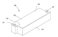
- FIG. 2 is an external perspective view showing a transmission unit according to an embodiment of the present invention.
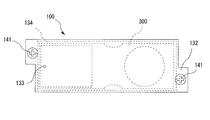
- FIG. 3 is a plan view showing a transmission unit according to an embodiment of the present invention.
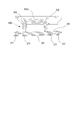
- FIG. 4 is a side cross-sectional view showing a transmission unit according to an embodiment of the present invention.
- FIG. 5 is an external perspective view showing a unit main body in one embodiment of the present invention.
- FIG. 6 is an external perspective view showing a unit main body in one embodiment of the present invention.
- FIG. 7 is an external perspective view showing the main part of the unit body in one embodiment of the present invention.
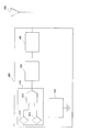
- FIG. 8 is a block diagram showing an electric circuit of the transmission unit in one embodiment of the present invention.
- FIG. 9 is an external perspective view showing a planar conductor plate and a holding material in one embodiment of the present invention.
- FIG. 10 is an external perspective view showing a holding material in one embodiment of the present invention.
- FIG. 11 is a Smith chart illustrating antenna characteristics according to an embodiment of the present invention.
- FIG. 12 is a flowchart for explaining the operation of the transmission unit according to the first embodiment of the present invention.
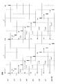
- FIG. 13 is a timing chart for explaining the operation of the transmission unit according to the first embodiment of the present invention.
- FIG. 14 is a flowchart for explaining the operation of the transmission unit according to the second embodiment of the present invention.
- FIG. 15 is a timing chart for explaining the operation of the transmission unit according to the second embodiment of the present invention.
- FIG. 1 is an external view showing a transmission device in one embodiment of the present invention
- FIG. 2 is an external perspective view showing a transmission unit in one embodiment of the present invention
- FIG. 3 is a plan view showing the transmission unit in one embodiment of the present invention.
- 4 is a side sectional view showing a transmission unit according to an embodiment of the present invention
- FIGS. 5 and 6 are external perspective views showing a unit main body according to an embodiment of the present invention
- FIG. 7 is an embodiment of the present invention.
- FIG. 8 is a block diagram showing an electric circuit of a transmission unit according to an embodiment of the present invention.
- reference numeral 10 denotes a transmitter, which is configured by accommodating eight transmitter units 100 (100a to 100h) in a cylindrical case 11 made of an insulator that transmits radio waves.
- Each of the transmission units 100 (100a to 100h) has the same shape, and is configured by housing the unit main body 300 in a substantially rectangular parallelepiped case 130 made of an insulator that transmits radio waves.
- the case 130 of the transmission unit 100 has a substantially rectangular parallelepiped shape, has protrusions for screwing at both ends in the longitudinal direction, and includes a case main body 131 and a lid 132. It is configured.
- a storage space 134 for storing the unit main body 300 is formed inside the case main body 131, and the opening of the storage space 134 is formed by fixing the lid 132 to the case main body 131 with screws 141. Closed.
- a vent hole 133 is formed in the lid body 132, and even when the lid body 132 is fixed to the case main body 131, air can flow from the outside to the storage space 134 through the vent hole 133. Yes.
- the unit main body 300 includes two printed wiring boards 351 and 352 having a substantially rectangular shape arranged in parallel at a predetermined interval, and a columnar connection constituting an antenna 450 therebetween.
- the conductor 354 and the third printed wiring board 353 for connection are fixed to each other.
- a coil-shaped antenna 450 having a central axis extending in the width direction of the first and second printed wiring boards 351 and 351 is formed at the other end portion in the longitudinal direction of the unit main body 300, and the sensor portion 410 and the battery are disposed at one end side.
- Electronic components that constitute an electronic circuit including 420 are mounted.
- the connecting printed wiring board 353 is soldered to each of the two printed wiring boards 351 and 352.
- the first printed wiring board 351 and the second printed wiring board 352 are provided between them, and fix the other printed wiring board to the one printed wiring board at a predetermined interval, and The printed wiring and the printed wiring of the other printed wiring board are connected by a plurality of columnar connecting conductors 354 that are conductively connected.
- the sensor unit 410 is mounted on the surface of the main body 300 and includes an air pressure detection element 411, a temperature detection element 412, and an analog / digital conversion circuit 413.
- an air pressure detection element 411 For example, the air pressure and temperature in the air chamber of a pneumatic fender Is detected by the air pressure detection element 411 and the temperature detection element 412, and the detection result is converted into a digital value by the analog / digital conversion circuit 413 and output to the main control unit 430.
- the battery 420 is connected to the unit main body 300 by a connection conductor, and supplies power to the detection / transmission / reception circuit 400 formed in the unit main body 300.
- the main control unit 430 includes a known CPU, a memory, a dip switch, and the like, receives a detection result by the sensor unit 410 as a digital value, generates digital information including the digital value, and outputs the digital information to the transmission / reception unit 440.
- the digital information includes identification information unique to the unit main body 300 that is set in advance (previously written in a memory or set by a dip switch),
- the unit main body 300 set in the dip switch includes a unique numerical value.
- the dip switch may be a flat type or a rotary type as long as it can set a numerical value representing any one of 1 to 8 which is a transmission order described later. In this embodiment, two dip switches are provided, a numerical value a indicating the order of transmission is set in the first dip switch, and the total number of transmission units 100 included in the transmission device 10 is set in the second dip switch. Value N is set.
- the main control unit 430 transmits the numerical value specific to the self and the information of the detection result based on the numerical value specific to the self set in the dip switch, or the reception information input from the transmission / reception unit 440 From this, a numerical value specific to the unit body is detected, and the detected numerical value is compared with a numerical value unique to the self set in the DIP switch, that is, a numerical value indicating the order of transmission. A unique numerical value and information on the detection result are transmitted.
- the transmission / reception unit 440 switches between transmission and reception based on an instruction from the main control unit 430.
- the digital information input from the main control unit 430 is transmitted from the antenna 450 with a predetermined frequency, for example, 315 MHz, and at the time of reception.
- a digital signal is detected from the 315 MHz radio wave received via the antenna 450, digital information is extracted from the detected digital signal, and is output to the main control unit 430.
- the transmission frequency and the reception frequency of the transmission / reception unit 440 are set to the same frequency.
- the antenna 450 is a coiled antenna whose resonance frequency is set to the transmission / reception frequency of the transmission / reception unit 440, and the printed wiring 351a provided on the first printed wiring board 351 and the printed wiring 352a provided on the second printed wiring board 352.
- the printed wiring of the first printed wiring board 351 and the printed wiring of the second printed wiring board 352 are conductively connected and formed by columnar connecting conductors 354 that fix the printed wiring boards 351 and 352 to each other.
- a rectangular planar conductor plate 361 is fixed to the outer surface of the other end of the first printed wiring board 351 by four holding members 371.
- a planar conductor plate 361 is provided at the position of the antenna 450 so as to be parallel to the printed wiring board 351 located on the bottom surface side of the case main body 131 when the unit main body 300 is accommodated in the case 130.
- the flat conductor plate 361 is fixed to the first printed wiring board 351 by a holding material 371 so as to maintain a predetermined distance.
- the planar conductor plate 361 is conductively connected to a predetermined conductor pattern (a conductor pattern connected to the negative electrode of the battery 420) of the first printed wiring board 351 and set to a reference potential. Further, as shown in FIG.
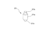
- the holding member 371 is fixed to the four corners of the planar conductor plate 361. As shown in FIG. 10, the holding member 371 has a shape in which cylindrical projections 371b having a diameter smaller than that of the main body 371a are provided at both ends of the cylindrical main body 371a.
- the antenna 450 has a resonance frequency of 315 MHz when the planar conductor plate 361 is mounted on the printed wiring board 351.
- the characteristic curve using the Smith chart is represented by the curve A shown in FIG. 11, and the antenna impedance at 315 MHz. Is 50 ohms.
- the distance D between the printed wiring board 351 and the flat conductor plate 361 at this time is set to 1.5 mm by the holding material 371.
- the eight transmission units 100 are accommodated in the case 11 of the transmission device 10 with a necessary minimum space, a reduction in transmission gain can be suppressed and good radio waves can be emitted. Eight transmission units 100 are arranged.
- the transmission timing can be automatically set only between the eight transmission units 100a to 100h.
- each of the transmission units 100a to 100h of the present embodiment corresponds to a wireless facility that uses radio waves having a frequency of 315 MHz, and therefore a predetermined transmission suspension time is used in wireless transmission for the purpose of avoiding interference. It is stipulated by law to provide it. According to this law, the transmission pause time is defined as 10 seconds or more.
- each transmission unit 100a to 100h transmits its own numerical value and the detection result information when its own numerical value is 1 at the time of activation.
- Each of the transmission units 100a to 100h measures the elapsed time from when the numerical value detected from the received signal input from the transmission / reception unit 440 matches the trigger value, and the measured elapsed time matches the predetermined time t. Sometimes, a numerical value unique to itself indicating the order of transmission and information on the detection result are transmitted.
- each transmission unit 100a to 100h When each transmission unit 100a to 100h is activated, it immediately reads a numerical value a indicating the transmission order set in the DIP switch and a numerical value N indicating the total number of the transmission units 100a to 100h provided in the transmission device 10 (SA1). Next, the transmission units 100a to 100h store the value obtained by dividing the value of time T by the numerical value N as time t (SA2). The time T is preset in the program.
- each of the transmission units 100a to 100h determines whether or not the read numerical value a is 1 (SA3), and when the numerical value a is 1, stores N as a trigger value b (SA4), which will be described later. The process proceeds to SA11.
- SA3 the read numerical value a is 1
- SA4 the numerical value a is 1
- SA5 a value obtained by subtracting 1 from the numerical value a is stored as the trigger value b (SA5).
- each of the transmission units 100a to 100h starts receiving signals transmitted by other transmission units and determines whether or not a signal has been received (SA6).
- a numerical value n representing the order is extracted (SA7), and it is determined whether or not the extracted numerical value n is equal to the trigger value b (SA8).
- SA6 A numerical value representing the order
- SA8 A numerical value n representing the order
- SA8 A numerical value n representing the order
- SA8 the extracted numerical value n is equal to the trigger value b
- the process proceeds to the above-described processing of SA6.
- the timer starts counting (SA9), and it is determined whether the timer has reached the time t described above. (SA10).
- SA11 the time measurement of the timer is terminated
- SA12 the detection detected by the sensor unit 410
- SA13 the detected value and its own transmission are transmitted.
- SA13 The information including the numerical value a indicating the order is transmitted (SA13). Thereafter, the process proceeds to SA6.
- each transmission unit 100a to 100h transmits the value of the number unique to itself and the information of the detection result when the number unique to the self is 1 at the time of activation.
- Each of the transmission units 100a to 100h measures the elapsed time from when the numerical value detected from the received signal input from the transmission / reception unit 440 matches 1, and the measured elapsed time is unique to the predetermined time t. Information on the detection result is transmitted when it coincides with the time multiplied by the numerical value.
- each transmission unit 100a to 100h When each transmission unit 100a to 100h is activated, it immediately reads a numerical value a indicating the transmission order set in the DIP switch and a numerical value N indicating the total number of the transmission units 100a to 100h provided in the transmission device 10 (SB1). Next, the transmission units 100a to 100h store the value obtained by dividing the value of time T by the numerical value N as time t (SB2). The time T is preset in the program.
- each of the transmission units 100a to 100h determines whether or not the read numerical value a is 1 (SB3), and when the numerical value a is 1, acquires the detection detected by the sensor unit 410 (SB4), Information including this detected value is transmitted (SB5). Thereafter, the transmission unit 100 with the numerical value a 1 starts time measurement by the timer (SB6), and determines whether or not the time measured by the timer has reached the time T described above (SB7). As a result of the determination, when the time measured by the timer reaches time T, the time measurement by the timer is terminated (SB8), and the process proceeds to the process of SB4.
- the transmission unit 100 having a numerical value a other than 1 starts receiving signals transmitted by other transmission units and determines whether or not the signals have been received (SB11). Then, a numerical value n representing the order of transmission is extracted (SB12), and it is determined whether or not the extracted numerical value n is 1 (SB13). As a result of this determination, when the extracted numerical value n is not 1, the process proceeds to the process of SB11 described above.
- the timer starts counting (SB14), and it is determined whether the timer has reached the time t1 (SB15). ). As a result of this determination, when the time measured by the timer reaches time t1, the time measurement of the timer is terminated (SB16), the detection detected by the sensor unit 410 is acquired (SB17), and information including this detected value is obtained. Transmit (SB18). Thereafter, the process proceeds to SB11.
- ROM Read Only Memory
- EEPROM Electrical Erasable and Programmable Read
- a memory such as “Only Memory” may be mounted on each of the transmission units 100a to 100h, and the identification information read from the memory may be transmitted in addition to the information detected by the sensor unit 410. Thereby, it is possible to determine the transmission device 10 to which information is transmitted when there are a plurality of transmission devices 10.
- the transmission unit 100 that can detect both the air pressure and the temperature is configured.
- a transmission unit that can detect either the air pressure or the temperature or another physical quantity may be configured.
- the transmission device is mounted on the pneumatic fender, but the present invention is not limited to this, and it goes without saying that the transmission device of the present invention can be applied to other than the pneumatic fender. That is.
- the transmission timing in each transmission unit automatically only by communication between multiple transmission units and emitting radio waves in order at predetermined time intervals, the transmission timing can be controlled from the outside of the multiple transmission units.
- a transmission apparatus that does not need to be set can be easily constructed.
Landscapes
- Physics & Mathematics (AREA)
- General Physics & Mathematics (AREA)
- Engineering & Computer Science (AREA)
- Computer Networks & Wireless Communication (AREA)
- Signal Processing (AREA)
- Arrangements For Transmission Of Measured Signals (AREA)
- Transmitters (AREA)
- Measuring Fluid Pressure (AREA)
Abstract
Description
Claims (5)
- 一定時間T経過毎に同一周波数の電波によって所定情報を送信するN個の送信ユニットを備えた送信装置であって、
前記各送信ユニットは、
予め設定された1~Nまでの送信の順番を表す数のうち他の送信ユニットに記憶されている数値とは異なる自己に固有の数値と数値Nとを記憶している情報記憶手段と、
前記自己に固有の数値から1を減算した値が正のときは該減算結果の値をトリガー値として記憶し、前記減算した値が負のときは前記Nの値をトリガー値として記憶するトリガー値決定手段と、
前記周波数の電波を受信する受信手段と、
起動時において前記自己に固有の数値が1であるときに前記自己に固有の数値と前記所定情報を送信する起動時送信手段と、
前記受信手段によって受信した電波の信号から前記数値を検出する検出手段と、
前記検出した数値が前記トリガー値と一致したときからの経過時間を計時する計時手段と、
前記計時手段によって計時された前記経過時間が前記一定時間Tよりも少ない所定時間tと一致したときに前記自己に固有の数値と前記所定情報を送信する送信手段とを備えている
ことを特徴とする送信装置。 - 一定時間T経過毎に同一周波数の電波によって所定情報を送信するN個の送信ユニットを備えた送信装置であって、
1つの基準送信ユニットを備え、
前記基準送信ユニットは、
予め設定された自己に固有の送信の順番を表す数値である1の値を記憶している情報記憶手段と、
前記自己に固有の数値と前記所定情報を前記一定時間T経過毎に送信する基準送信手段とを備え、
前記基準送信ユニット以外の送信ユニットは、
予め設定された1~Nまでの数のうち1以外の送信の順番を表す数であり且つ他の送信ユニットに記憶されている数とは異なる自己に固有の数値を記憶している情報記憶手段と、
前記自己に固有の数値から1を減算した値を倍数cとして記憶する倍数決定手段と、
前記周波数の電波を受信する受信手段と、
前記受信手段によって受信した電波の信号から前記数値を検出する検出手段と、
前記検出手段によって検出した数値が1に一致したときからの経過時間を計時する計時手段と、
前記計時手段によって計時された前記経過時間が前記一定時間Tよりも少ない所定時間tに対して前記倍数cを乗算して得られた時間と一致したときに前記所定情報を送信する送信手段とを備えている
ことを特徴とする送信装置。 - 時間tが前記一定時間Tを前記Nで除算した値(T/N)に設定されている
ことを特徴とする請求項1又は2に記載の送信装置。 - 前記各送信ユニットは、周囲の空気圧を検出するセンサと、前記センサの検出値の情報を前記所定情報とする手段とを備えている
ことを特徴とする請求項1又は2に記載の送信装置。 - 前記各送信ユニットは、
各送信ユニット毎に異なる識別情報が予め記憶されている識別情報記憶手段と、
前記識別情報を前記所定情報とともに送信する手段とを備えている
ことを特徴とする請求項1又は2に記載の送信装置。
Priority Applications (4)
| Application Number | Priority Date | Filing Date | Title |
|---|---|---|---|
| US13/884,532 US8611831B2 (en) | 2010-11-10 | 2011-07-14 | Transmission device |
| EP11839779.3A EP2639963B1 (en) | 2010-11-10 | 2011-07-14 | Transmission device |
| KR1020137011533A KR101303621B1 (ko) | 2010-11-10 | 2011-07-14 | 송신 장치 |
| CN201180053538.3A CN103210594B (zh) | 2010-11-10 | 2011-07-14 | 发送装置 |
Applications Claiming Priority (2)
| Application Number | Priority Date | Filing Date | Title |
|---|---|---|---|
| JP2010-251820 | 2010-11-10 | ||
| JP2010251820A JP4858734B1 (ja) | 2010-11-10 | 2010-11-10 | 送信装置 |
Publications (1)
| Publication Number | Publication Date |
|---|---|
| WO2012063527A1 true WO2012063527A1 (ja) | 2012-05-18 |
Family
ID=45604536
Family Applications (1)
| Application Number | Title | Priority Date | Filing Date |
|---|---|---|---|
| PCT/JP2011/066130 Ceased WO2012063527A1 (ja) | 2010-11-10 | 2011-07-14 | 送信装置 |
Country Status (6)
| Country | Link |
|---|---|
| US (1) | US8611831B2 (ja) |
| EP (1) | EP2639963B1 (ja) |
| JP (1) | JP4858734B1 (ja) |
| KR (1) | KR101303621B1 (ja) |
| CN (1) | CN103210594B (ja) |
| WO (1) | WO2012063527A1 (ja) |
Cited By (2)
| Publication number | Priority date | Publication date | Assignee | Title |
|---|---|---|---|---|
| WO2013187162A1 (ja) * | 2012-06-13 | 2013-12-19 | 横浜ゴム株式会社 | 送信装置及びこれを備えた防舷材 |
| US20150158564A1 (en) * | 2012-07-23 | 2015-06-11 | The Yokohama Rubber Co., Ltd. | Ship monitoring device |
Families Citing this family (2)
| Publication number | Priority date | Publication date | Assignee | Title |
|---|---|---|---|---|
| JP5888232B2 (ja) * | 2010-12-02 | 2016-03-16 | 横浜ゴム株式会社 | 情報取得装置を備えたタイヤ |
| WO2023027075A1 (ja) * | 2021-08-27 | 2023-03-02 | 日本碍子株式会社 | 通信装置、スマートメーター、二次電池 |
Citations (4)
| Publication number | Priority date | Publication date | Assignee | Title |
|---|---|---|---|---|
| JPH0668326A (ja) * | 1992-08-24 | 1994-03-11 | Omron Corp | 非接触パスゲートシステム |
| JP2008153783A (ja) * | 2006-12-14 | 2008-07-03 | Hitachi Ltd | 無線通信システムおよび無線端末装置 |
| JP2008294604A (ja) * | 2007-05-23 | 2008-12-04 | Panasonic Electric Works Co Ltd | 無線認証システムおよびそのセンサ |
| JP2010175298A (ja) | 2009-01-27 | 2010-08-12 | Yokohama Rubber Co Ltd:The | 空気式防舷材の空気圧監視装置及びその集中管理システム |
Family Cites Families (8)
| Publication number | Priority date | Publication date | Assignee | Title |
|---|---|---|---|---|
| US5019815A (en) * | 1979-10-12 | 1991-05-28 | Lemelson Jerome H | Radio frequency controlled interrogator-responder system with passive code generator |
| JPH09318478A (ja) * | 1996-05-27 | 1997-12-12 | Yokohama Rubber Co Ltd:The | 空気式防舷材の内圧検知装置 |
| EP0813321A3 (de) * | 1996-06-14 | 2001-05-09 | TEMIC TELEFUNKEN microelectronic GmbH | Verfahren und Steuersystem zum Übertragen von Daten |
| JP3177637B2 (ja) * | 1997-02-05 | 2001-06-18 | 広島大学長 | パルス幅変調演算回路 |
| WO1999020845A1 (en) * | 1997-10-22 | 1999-04-29 | The Yokohama Rubber Co., Ltd. | Fender and a management system therefor |
| JP4289561B2 (ja) * | 2004-12-24 | 2009-07-01 | 横浜ゴム株式会社 | 車両の異常検出方法及びその装置並びにそのセンサユニット |
| JP4604755B2 (ja) * | 2005-02-15 | 2011-01-05 | 横浜ゴム株式会社 | タイヤ情報送信装置およびこれを用いたタイヤ情報取得システム |
| JP4270284B2 (ja) * | 2007-01-30 | 2009-05-27 | トヨタ自動車株式会社 | 車輪状態監視システムおよび車輪状態検出装置 |
-
2010
- 2010-11-10 JP JP2010251820A patent/JP4858734B1/ja not_active Expired - Fee Related
-
2011
- 2011-07-14 US US13/884,532 patent/US8611831B2/en not_active Expired - Fee Related
- 2011-07-14 KR KR1020137011533A patent/KR101303621B1/ko not_active Expired - Fee Related
- 2011-07-14 CN CN201180053538.3A patent/CN103210594B/zh not_active Expired - Fee Related
- 2011-07-14 EP EP11839779.3A patent/EP2639963B1/en not_active Not-in-force
- 2011-07-14 WO PCT/JP2011/066130 patent/WO2012063527A1/ja not_active Ceased
Patent Citations (4)
| Publication number | Priority date | Publication date | Assignee | Title |
|---|---|---|---|---|
| JPH0668326A (ja) * | 1992-08-24 | 1994-03-11 | Omron Corp | 非接触パスゲートシステム |
| JP2008153783A (ja) * | 2006-12-14 | 2008-07-03 | Hitachi Ltd | 無線通信システムおよび無線端末装置 |
| JP2008294604A (ja) * | 2007-05-23 | 2008-12-04 | Panasonic Electric Works Co Ltd | 無線認証システムおよびそのセンサ |
| JP2010175298A (ja) | 2009-01-27 | 2010-08-12 | Yokohama Rubber Co Ltd:The | 空気式防舷材の空気圧監視装置及びその集中管理システム |
Non-Patent Citations (1)
| Title |
|---|
| See also references of EP2639963A4 |
Cited By (6)
| Publication number | Priority date | Publication date | Assignee | Title |
|---|---|---|---|---|
| WO2013187162A1 (ja) * | 2012-06-13 | 2013-12-19 | 横浜ゴム株式会社 | 送信装置及びこれを備えた防舷材 |
| CN104364966A (zh) * | 2012-06-13 | 2015-02-18 | 横滨橡胶株式会社 | 发射装置及设有该发射装置的护舷木 |
| AU2013275528B2 (en) * | 2012-06-13 | 2016-01-28 | The Yokohama Rubber Co., Ltd. | Transmission device, and fender provided therewith |
| US9385761B2 (en) | 2012-06-13 | 2016-07-05 | The Yokohama Rubber Co., Ltd. | Transmission device, and fender provided therewith |
| US20150158564A1 (en) * | 2012-07-23 | 2015-06-11 | The Yokohama Rubber Co., Ltd. | Ship monitoring device |
| US9334029B2 (en) * | 2012-07-23 | 2016-05-10 | The Yokohama Rubber Co., Ltd. | Ship monitoring device |
Also Published As
| Publication number | Publication date |
|---|---|
| JP4858734B1 (ja) | 2012-01-18 |
| US20130231063A1 (en) | 2013-09-05 |
| CN103210594A (zh) | 2013-07-17 |
| EP2639963A1 (en) | 2013-09-18 |
| CN103210594B (zh) | 2014-11-05 |
| JP2012105061A (ja) | 2012-05-31 |
| KR101303621B1 (ko) | 2013-09-11 |
| KR20130054462A (ko) | 2013-05-24 |
| EP2639963B1 (en) | 2015-08-19 |
| US8611831B2 (en) | 2013-12-17 |
| EP2639963A4 (en) | 2014-05-07 |
Similar Documents
| Publication | Publication Date | Title |
|---|---|---|
| JP4858734B1 (ja) | 送信装置 | |
| US8400316B2 (en) | Electronic thermometer | |
| US9635477B2 (en) | Hearing aid with capacitive switch | |
| EP4231545A3 (en) | Temperature sensing devices and wireless communication improvements for cooking appliances | |
| JP2012105062A (ja) | 情報取得装置 | |
| JP4868192B2 (ja) | タイヤ状態検出装置 | |
| US5008665A (en) | Measuring device having transmitter | |
| KR20130081287A (ko) | 송신 장치 | |
| JP2016023490A (ja) | アンテナユニット | |
| US9385761B2 (en) | Transmission device, and fender provided therewith | |
| JPWO2013187163A1 (ja) | 状態検出装置 | |
| JP2013108812A (ja) | 記録装置及びセンシングシステム | |
| KR101655869B1 (ko) | 표면탄성파를 이용한 온도센서 및 온도 측정기 그리고 이를 이용한 실시간 패시브 온도측정 시스템 | |
| US6980924B2 (en) | Weighing systems | |
| JP2018169332A (ja) | 超音波音圧測定装置 | |
| JP2010197117A (ja) | 温度計測用のicタグ | |
| CN111566451A (zh) | 用于监控对象的设备 | |
| JP4284513B2 (ja) | 無線送信機、データ収集システム及びデータ通信方法 | |
| KR102710052B1 (ko) | 전기화학 발전기에 결합된 음향 센서의 오작동을 검출하기 위한 방법 및 이 방법을 구현하는 장치 | |
| KR20170053162A (ko) | Saw 온도센서에 의한 측정 온도 수신 시스템 | |
| CN118624046B (zh) | 一种蓝牙温度探针和温度测量装置 | |
| JP2007178175A (ja) | 結露検出装置及び結露検出方法 | |
| KR20160141365A (ko) | 표면탄성파를 이용한 온도센서 및 온도 측정기 그리고 이를 이용한 실시간 패시브 온도측정 시스템 | |
| CN117928645A (zh) | 一种基于无线通信技术高自身传感器精度的仪表装置 | |
| CN116564051A (zh) | 一种食物测温设备及处理方法、存储介质、电子设备 |
Legal Events
| Date | Code | Title | Description |
|---|---|---|---|
| 121 | Ep: the epo has been informed by wipo that ep was designated in this application |
Ref document number: 11839779 Country of ref document: EP Kind code of ref document: A1 |
|
| ENP | Entry into the national phase |
Ref document number: 20137011533 Country of ref document: KR Kind code of ref document: A |
|
| WWE | Wipo information: entry into national phase |
Ref document number: 2011839779 Country of ref document: EP |
|
| WWE | Wipo information: entry into national phase |
Ref document number: 13884532 Country of ref document: US |
|
| NENP | Non-entry into the national phase |
Ref country code: DE |