WO2012063531A1 - 無線通信装置及び無線通信システム - Google Patents
無線通信装置及び無線通信システム Download PDFInfo
- Publication number
- WO2012063531A1 WO2012063531A1 PCT/JP2011/067434 JP2011067434W WO2012063531A1 WO 2012063531 A1 WO2012063531 A1 WO 2012063531A1 JP 2011067434 W JP2011067434 W JP 2011067434W WO 2012063531 A1 WO2012063531 A1 WO 2012063531A1
- Authority
- WO
- WIPO (PCT)
- Prior art keywords
- wireless communication
- control
- control data
- external device
- unit
- Prior art date
- Legal status (The legal status is an assumption and is not a legal conclusion. Google has not performed a legal analysis and makes no representation as to the accuracy of the status listed.)
- Ceased
Links
Images


Classifications
-
- H—ELECTRICITY
- H04—ELECTRIC COMMUNICATION TECHNIQUE
- H04W—WIRELESS COMMUNICATION NETWORKS
- H04W4/00—Services specially adapted for wireless communication networks; Facilities therefor
- H04W4/80—Services using short range communication, e.g. near-field communication [NFC], radio-frequency identification [RFID] or low energy communication
-
- A—HUMAN NECESSITIES
- A61—MEDICAL OR VETERINARY SCIENCE; HYGIENE
- A61B—DIAGNOSIS; SURGERY; IDENTIFICATION
- A61B1/00—Instruments for performing medical examinations of the interior of cavities or tubes of the body by visual or photographical inspection, e.g. endoscopes; Illuminating arrangements therefor
- A61B1/00002—Operational features of endoscopes
- A61B1/00011—Operational features of endoscopes characterised by signal transmission
- A61B1/00016—Operational features of endoscopes characterised by signal transmission using wireless means
-
- G—PHYSICS
- G08—SIGNALLING
- G08C—TRANSMISSION SYSTEMS FOR MEASURED VALUES, CONTROL OR SIMILAR SIGNALS
- G08C17/00—Arrangements for transmitting signals characterised by the use of a wireless electrical link
- G08C17/02—Arrangements for transmitting signals characterised by the use of a wireless electrical link using a radio link
-
- A—HUMAN NECESSITIES
- A61—MEDICAL OR VETERINARY SCIENCE; HYGIENE
- A61B—DIAGNOSIS; SURGERY; IDENTIFICATION
- A61B17/00—Surgical instruments, devices or methods
- A61B2017/00017—Electrical control of surgical instruments
- A61B2017/00221—Electrical control of surgical instruments with wireless transmission of data, e.g. by infrared radiation or radiowaves
-
- A—HUMAN NECESSITIES
- A61—MEDICAL OR VETERINARY SCIENCE; HYGIENE
- A61B—DIAGNOSIS; SURGERY; IDENTIFICATION
- A61B17/00—Surgical instruments, devices or methods
- A61B2017/00017—Electrical control of surgical instruments
- A61B2017/00225—Systems for controlling multiple different instruments, e.g. microsurgical systems
Definitions
- the present invention relates to a wireless communication device and a wireless communication system that perform wireless communication of control data for remotely controlling an external device.
- Priority is claimed on Japanese Patent Application No. 2010-251969, filed Nov. 10, 2010, the content of which is incorporated herein by reference.
- a surgical system which is configured of a plurality of medical device groups on which a medical device according to the purpose is mounted on a cart. Medical devices are freely arranged according to the contents of the operation.
- remote control a remote controller
- Many remote controls transmit control data to medical devices by infrared communication. Since the communication distance of infrared communication is short, transmission of control data by infrared communication causes a problem that control data can not be transmitted when the medical device is disposed in a wide range.
- Patent Document 1 discloses a method of increasing the amount of infrared light by means of an infrared adapter and transmitting control data to medical devices distant from each other.
- this method does not solve the problem associated with infrared communication that communication can not be performed if the communication partner is not at a communicable position, and thus there remains a problem that control data can not be transmitted depending on the arrangement of medical devices and doctors. .
- Patent Document 2 discloses the use of a remote control using a radio (radio wave) having a long communication distance.
- a radio radio wave
- Patent Document 3 discloses a method of preventing a collision by performing detection before transmission when communicating between remote controls.
- this method does not consider the occurrence of radio communication or electromagnetic noise other than communication between remote controls, and is an effective method when the generated radio communication or electromagnetic noise is small, but radio communication or electromagnetic noise
- this method is used for a surgical system which often causes the occurrence of other radio communication or electromagnetic noise immediately after the start of transmission, the control data may not be transmitted properly.
- JP 2003-245286 A Japanese Patent Publication No. 2008-519501 Japanese Patent Application Laid-Open No. 7-147697
- image data such as endoscopic images are often communicated wirelessly (radio waves) and displayed on monitors of other medical device groups.
- a device such as an electric knife that generates electromagnetic noise during operation is often used. That is, the medical device group is distributed over a wide range, and there are many cases where a device using radio waves or a device generating radio waves is used.
- the present invention provides a wireless communication apparatus and a wireless communication system capable of favorably communicating control data.
- the wireless communication apparatus is close to a control terminal and a wireless communication unit for performing wireless communication using radio waves belonging to a predetermined radio wave band between the first external device and the second external device.
- a proximity communication unit performing communication and control data indicating an instruction for the first external device received from the control terminal via the proximity communication unit are transmitted to the first external device via the wireless communication unit.
- a control unit that transmits data, in which the control data is transmitted to the first external device while the first external device or the wireless communication unit sequentially transmits data to the second external device.
- a control unit that adjusts transmission timing of the control data or the data.
- a wireless communication unit performing wireless communication using radio waves belonging to a predetermined radio wave band with an external device
- a proximity communication unit performing proximity communication between the control terminal and A control unit for transmitting control data indicating an instruction to the external device, received from the control terminal via the proximity communication unit, to the external device via the wireless communication unit, the predetermined frequency band
- a controller configured to adjust the transmission timing of the control data or to change the operation state of the device based on the operation state of the device emitting a radio wave belonging to
- the control unit is configured to transmit the control data while the first external device or the wireless communication unit sequentially transmits image data to the second external device.
- the transmission timing of the control data may be adjusted to a timing different from the predetermined wireless transmission period of the image data.
- the wireless communication unit has a function of performing wireless communication of image data with the first external device, and using the function, the control data is transmitted to the first external device. It may be sent to the device.
- the control unit may adjust the transmission timing of the control data to a timing at which it is determined that the generation of electromagnetic noise by the equipment is small.
- the external device includes the devices individually having a priority
- the control data indicates ID information assigned to each of the devices and an operation of the devices.
- a storage unit storing equipment information in which the ID information and the priority are associated with each other, the control unit including the ID information included in the control data and the equipment information.
- the priority of the equipment to be controlled is identified based on that, the equipment whose operation state is to be changed is determined based on the identified priority and the priority of each equipment indicated by the equipment information, and the operation of the equipment An instruction to change the state may be sent to the device.
- the wireless communication unit has a function of performing wireless communication of image data with the external device, and the control data may be transmitted to the external device using the function. Good.
- a first wireless communication unit for performing wireless communication using radio waves belonging to a predetermined radio wave band between a first external device and a second external device, and a control terminal And control data indicating an instruction to the first external device received from the control terminal via the first proximity communication unit.
- Control unit configured to transmit data to the first external device via the wireless communication unit, while the first external device or the wireless communication unit sequentially transmits data to the second external device
- a wireless communication device having a first control unit that adjusts transmission timing of the control data or the data when transmitting the control data to the first external device; a generation unit that generates the control data; Proximity with the wireless communication device Performing a wireless communication using radio waves belonging to the predetermined radio wave band between the control terminal having a second proximity communication unit for performing communication, the second external device, and the wireless communication device; And a second control unit that performs control based on the control data received from the wireless communication apparatus via the second wireless communication unit.
- proximity communication is performed between a control terminal and a first wireless communication unit that performs wireless communication using a radio wave belonging to a predetermined radio wave band with an external device.
- Control data indicating an instruction to the external device which is received from the control terminal via the first proximity communication unit and the first proximity communication unit, is transmitted to the external device via the first wireless communication unit.
- the control unit to adjust the transmission timing of the control data or change the operating condition of the device based on the operating condition of the device emitting the radio wave belonging to the predetermined frequency band;
- a wireless communication apparatus having a first control unit to transmit to the control unit; a generation unit generating the control data; and a second proximity communication unit performing proximity communication with the wireless communication apparatus Terminal, wireless A second wireless communication unit performing wireless communication using a radio wave belonging to the predetermined radio wave band with the receiving apparatus; and the control received from the wireless communication apparatus via the second wireless communication unit And a second control unit that performs control based on data.
- the control data includes ID information assigned to each of the devices to be controlled, and instruction information for instructing the operation of the devices, and the control terminal displays an image.
- the control data may be generated using the ID information read from
- the control data includes ID information assigned to each of the devices to be controlled, and instruction information for instructing the operation of the devices, and the control terminal displays an image.
- the control data may be generated using the ID information read from
- the wireless communication apparatus when the wireless communication apparatus transmits control data from the control terminal, it adjusts the transmission timing of data such as control data or image data, or releases an electric wave belonging to a predetermined frequency band.
- data such as control data or image data
- the wireless communication apparatus By transmitting an instruction to change the operation state to the equipment, it becomes possible to transmit the control data at a timing when no radio wave affecting the transmission of the control data is generated, so the control data can be communicated favorably. be able to.
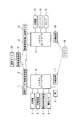
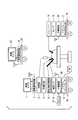
- FIG. 1 shows the configuration of the remote control system according to the present embodiment.
- the cart 10 includes an image monitor 1 for displaying endoscopic images and various control screens, a wireless communication device 2 for communicating image data and control data, an endoscope 3, an insufflation device 4, an ultrasonic processing device 5, An electric knife 6, a relay unit 7, a system controller 8 and a foot switch 9 are mounted. These devices on the cart 10 constitute an external device in the wireless communication system of the present invention.
- the cart 18 includes an image monitor 11 for displaying endoscopic images and various control screens, a wireless communication device 12 for communicating image data and control data, an endoscope 13, a shaver 14, a pump 15, a relay device 16, and a system A controller 17 is mounted. These devices on the cart 18 constitute an external device (first external device) in the wireless communication system of the present invention.
- the remote control 19 for remote control of each medical device is in the vicinity of the cart 18, and the signal from the remote control 19 is in a state of being transmitted only to the relay device 16 by infrared communication.
- the remote control 19 is in the vicinity of the cart 18 in FIG. 1, when the remote control 19 is in the vicinity of the cart 10, the signal from the remote control 19 is transmitted only to the relay device 7 on the cart 10.
- An image monitor 20 and a wireless communication device 21 are mounted on the cart 22, and the image monitor 20 displays an image received by the wireless communication device 21.
- These devices on the cart 22 constitute an external device (second external device) in the wireless communication system of the present invention.
- a patient 23 is placed on a patient bed 24 and a probe from a medical device such as an endoscope is attached.
- an endoscope, an insufflation apparatus, an ultrasonic processing apparatus, an electric scalpel, a shaver, and a pump are known medical apparatuses, and in the present embodiment, they are described as articles having known functions. Further explanation is omitted.
- the foot switch 9 is connected to the system controller 8 and controls the output of the ultrasonic processor 5 or the electric knife 6. By switching the operation state of the foot switch 9, the remote control 19 can switch which of the ultrasonic processing device 5 and the electric knife 6 is to be controlled.
- the wireless communication device the relay device, the system controller, and the remote control will be described later.
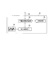
- FIG. 2 shows the connection relationship of each medical device that the remote control system has.
- each device (equipment) mounted on the cart 10 is connected to the system controller 8, and the system controller 8 grasps the operation state of each device.
- each device (equipment) mounted on the cart 18 is connected to the system controller 17, and the system controller 17 grasps the operation state of each device.
- FIG. 2 shows a state in which the signal output from the remote control 19 is transmitted only to the relay device 16.
- the relay device 7 grasps the operation state of each device mounted on the cart 10 based on the information from the system controller 8 and also uses the relay device 16 by wireless communication via the wireless communication device 2 and the wireless communication device 12. The information exchange is carried out, and the operation state of each device mounted on the cart 18 is also grasped.
- the relay device 16 grasps the operation state of each device mounted on the cart 18 based on the information from the system controller 17, and by wireless communication via the wireless communication device 2 and the wireless communication device 12. The information exchange with the relay device 7 is performed, and the operation state of each device mounted on the cart 10 is also grasped. The method of grasping the operation state of each device by these relay devices will be described in detail later with reference to FIGS. 5 to 11.
- the wireless communication device 2 of the cart 10, the wireless communication device 12 of the cart 18, and the wireless communication device 21 of the cart 22 perform wireless communication belonging to a predetermined radio wave band (frequency band). These wireless communication devices have an image communication function, and in FIG. 2, the wireless communication device 2 of the cart 10 and the wireless communication device 21 of the cart 22 perform wireless communication of image data. Also, the wireless communication device 2 of the cart 10 and the wireless communication device 12 of the cart 18 perform wireless communication of control data for controlling the operation of each device using an image communication function.
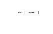
- FIG. 3 shows the structure of control data (control instruction) transmitted from the remote control 19.
- the control data includes an apparatus ID (ID information) indicating an ID of an apparatus to be controlled and instruction information indicating an instruction content (control content) for the apparatus to be controlled.
- ID information an apparatus ID
- instruction information indicating an instruction content (control content) for the apparatus to be controlled.
- FIG. 4 shows the configuration of the remote control 19.
- the remote control 19 includes an infrared light emitting element 27, a visible light receiving element 28, a communication interface circuit 30, a control button 26, a display element 25, a storage circuit 31, and a remote control control circuit 29.
- the infrared light emitting element 27 transmits control data by infrared communication. Since infrared rays are used, the communication between the remote control 19 and the relay devices 7 and 16 is not easily affected by the electromagnetic noise generated by the electric knife 6 or the like. In the embodiment of the present invention, an example is shown in which the remote control 19 performs infrared communication, but the communication performed by the remote control 19 may be close proximity communication (short distance communication) in which communication can be performed only in the vicinity of the relay device. Instead of infrared light, ultrasonic waves may be used.
- the visible light receiving element 28 receives the device ID of each device by optical communication through the image monitor. The reception of the device ID by the optical communication will be described in detail later with reference to FIG.
- the communication interface circuit 30 communicates using the infrared light emitting element 27 and the visible light receiving element 28.
- the control button 26 receives an operation input for instructing the operation of the remote control 19.
- the display element 25 displays the operation state of the remote control 19.
- the storage circuit 31 stores the device ID received by optical communication.
- the remote control control circuit 29 controls the overall operation of the remote control 19.
- the remote control circuit 29 interprets the instruction content to generate instruction information, and displays the result on the display element 25.
- the control data is generated by adding the device ID stored in the storage circuit 31 to the instruction information.
- the control data is transmitted by infrared light via the communication interface circuit 30 and the infrared light emitting element 27, and is received by a nearby relay device.
- FIG. 5 shows the configuration of the relay device 16.
- the relay device 16 includes an infrared light receiving element 32, an infrared interface circuit 33, a relay device control circuit 34, and a storage circuit 35.
- the infrared light receiving element 32 receives control data from the remote control 19 by infrared communication.
- the infrared interface circuit 33 processes the signal from the infrared light receiving element 32 and transmits it to the relay device control circuit 34.
- the relay device control circuit 34 controls the entire relay device 16.
- the storage circuit 35 includes a system state table indicating a list of the state of each device (equipment) on the cart 10 and the state of each device (machine) on the cart 18, and control data waiting for transmission to the relay device.
- a control data transmission waiting table indicating a list is stored.
- the relay device 7 is connected to the system controller 17 via the relay device input / output signal 36 from the relay device control circuit 34.
- the configuration of the relay device 7 is also the same as that of the relay device 16.
- the relay device 16 When the relay device 16 receives control data from the remote control 19, the relay device 16 notifies a system controller to which a device to be controlled is connected based on the device ID in the control data.
- the system controller having received the control command appropriately controls the target apparatus based on the control command.
- control instruction is an instruction for the shaver 14
- the relay device 16 directly controls the control instruction based on the received control data.
- the control command is a command to the insufflation device 4
- the insufflation device 4 is connected to the system controller 8 of the cart 10 on which the relay device 7 is placed.
- the control data is transmitted to the relay device 7 by communication, and the relay device 7 notifies the system controller 8 of a control command.
- FIG. 6 is an example of a system status table.
- the system status table is performed by grasping the operation status of the device on the cart in which the relay device in the remote control system is mounted, determination as to whether or not to transmit control data from the remote control 19 by wireless communication, and wireless communication Is a table used for determining the start timing of the
- the type of the device mounted on each cart, the device ID, the operation state, and the presence or absence of the electromagnetic noise generated during the device operation are recorded.
- the electric knife 6 mounted on the cart 10 is registered as device ID: SG-001, operating state: operating, electromagnetic noise generated at the time of device operation: present. This indicates that wireless communication of control data from the remote control 19 can not be performed because electromagnetic noise occurs when the electric knife 6 is in operation.
- FIG. 7 is an example of a control data transmission waiting table used by the relay device.
- the control data transmission waiting table is a table in which among control data received from the remote control 19, control data to be transmitted by wireless communication to a relay device of another cart is summarized.
- the ID of the relay device to be the transmission destination the type of the device to be controlled, the device ID, the control content, and the reception time based on the reception of control data are recorded.
- FIG. 7 shows an example in which an instruction to change the connection destination of the foot switch from the current electric knife 6 to the ultrasonic processing device 5 and an instruction to change the flow rate of the insufflation device 4 are registered. .
- the image of the endoscope 3 is in communication with the wireless communication device 21 connected to the image monitor 20 via the wireless communication device 2 and the wireless communication device 21, and the remote controller 19 is shown in FIG.
- the control contents (change of connection destination of foot switch, change of flow rate of insufflation device) are instructed to the relay device 16 and the electric knife 6 is in operation at first and then stopped as an example.
- FIG. 8 shows how control data is wirelessly transmitted in the above procedure.
- the electric knife 6 is in operation until time t6 and then stops.
- the wireless communication device 2 periodically transmits the image of the endoscope 3. For example, when one frame is composed of 60 images, the transfer cycle is 16.7 ms, and in the figure, the period from time t1 to t5 is 16.7 ms.
- a period of time t4 to t5 is a blanking period in which image data is not transmitted, and control data is wirelessly communicated using this period.
- the contents of the wireless communication may not be transmitted accurately. Since image data is transmitted continuously, it is acceptable even if the screen is disturbed by the influence of electromagnetic noise, but since errors in control data may cause serious problems, electromagnetic noise is generated. The wireless communication of control data is not performed during the period.
- control data indicating a control command (change in flow rate of the insufflation device) from the remote control 19 is transmitted to the relay device 16 in a period from time t2 to t3.
- the control data received by the relay device 16 is added to the control data transmission waiting table.
- new control is performed after control data indicating a change instruction of the connection destination of the foot switch instructed previously. Data is added.
- the relay device 16 controls the transmission timing of control data so that the wireless communication device 21 transmits control data in the blanking period after the electric knife 6 is stopped.
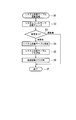
- FIGS. 9 to 11 are common to the relay device 7 and the relay device 16. Also, the processing shown in FIGS. 9 to 11 is performed by software under the control of the OS, and after the processing is completed, another software under the control of the OS is executed.
- FIG. 9 shows the system state table update process (S1).
- the relay device In the system status table update process (S1), the relay device periodically monitors the status of each device connected to the system controller via the system controller to which the relay device is connected, and updates the system status table. It is a process.
- the relay device control circuit 34 In the system state table update process (S1), the relay device control circuit 34 first checks the state of each device via the system controller (S2). Subsequently, the relay device control circuit 34 compares the contents of the system state table stored in the storage circuit 35 with the state of each device notified from the system controller (S3). If there is no change in the state of each device, the system state table update process (S1) ends (S7). If there is a change in the status of each device, the relay device control circuit 34 updates the system status table (S4), turns the system status table flag ON (S5), and turns the transmission activation flag ON (S6). The state table update process (S1) is ended (S7).
- the system state table flag is a flag indicating that the system state table has been updated
- the transmission activation flag is a flag that requests activation of the wireless transmission process (S8) described below.
- FIG. 10 shows the wireless transmission process (S8).
- the wireless transmission process (S8) is a process of transmitting the contents of the system state table and the control data transmission waiting table. If the transmission activation flag is ON, the wireless transmission process (S8) is activated, and if the system state table flag is ON, the system state table updated by the system state table update process (S1) is transmitted, and control data transmission is awaited. When the table flag is ON, the contents of the control data transmission waiting table are transmitted.
- the relay device control circuit 34 checks the system state table by the transmission environment check (S9), and determines whether transmission is possible. When the device registered as electromagnetic noise: Yes is operating, the relay device control circuit 34 determines that transmission is not possible and repeats the transmission environment check (S9). If the device registered as electromagnetic noise: present is not operating, the relay device control circuit 34 checks the system state table flag (S10). When the system status table flag is ON, the relay device control circuit 34 executes the system status table transmission process (S11) and the system status table flag OFF process (S12), and then checks the control data transmission wait table flag (S13). Run. When the system state table flag is OFF, the relay device control circuit 34 executes the control data transmission waiting table flag check (S13) as it is.
- the system state table updated by the system state table update process (S1) is transmitted.
- the relay device control circuit 34 outputs the system state table to the wireless communication device via the system controller, and the wireless communication device uses the next blanking period to perform another wireless communication Send the system status table to the device.
- the system status table received by the other wireless communication device is output to the relay device via the system controller.
- the relay device control circuit 34 updates the system state table stored in the storage circuit 35.
- the relay device control circuit 34 turns off the system state table flag (S12).
- the relay device control circuit 34 checks the control data transmission waiting table flag. When the control data transmission waiting table flag is ON, the relay device control circuit 34 executes control data transmission waiting table transmission processing (S14) and control data transmission waiting table flag OFF processing (S15), and thereafter, the transmission activation flag OFF processing Execute (S16).
- the relay device control circuit 34 In the control data transmission waiting table transmission process (S14), the relay device control circuit 34 outputs control data to the wireless communication device via the system controller, and the wireless communication device uses the next blanking period to transmit another wireless signal. Send control data to the communication device. After the control data transmission waiting table transmission processing (S14), the relay device control circuit 34 turns off the control data transmission waiting table flag and the transmission activation flag (S15, S16), and ends the wireless transmission processing (S8).
- the relay device control circuit 34 executes the transmission start flag OFF processing (S16) as it is. After the transmission activation flag OFF process (S16), the wireless transmission process (S8) ends (S17).
- FIG. 11 shows remote control data reception processing (S18).
- the remote control data reception process (S18) is a process performed when the control data from the remote control 19 is received.
- the relay device control circuit 34 starts remote control data reception processing (S18).
- the relay device control circuit 34 first receives control data (S19), and then performs wireless transmission execution determination (S20).
- the relay device control circuit 34 executes the device position determination (S24), and otherwise executes the update of the control data transmission waiting table (S21). It should be noted that the determination as to which relay device the communication from the remote control 19 has reached determines whether the operation status of all the relay devices in the system status table shown in FIG. 6 is "remote control connected". By doing.
- the relay device control circuit 34 determines the device to be controlled from the device ID in the control data. When the device to be controlled is in the same cart as itself, the relay device control circuit 34 executes control command notification (S25) to the system controller and ends remote control data reception processing (S18) (S26), otherwise In this case, the remote control data reception process (S18) is immediately ended (S26).
- the relay device control circuit 34 adds the control data received from the remote controller 19 to the control data transmission waiting table stored in the storage circuit 35. At this time, for control data that is control data for the same device and for which control content (for example, flow rate change of the insufflation device) is duplicated, only the latest control data is stored in the control data transmission wait table based on the acceptance time It is put.
- the relay device control circuit 34 After updating the control data transmission waiting table (S21), the relay device control circuit 34 turns on the control data transmission waiting table flag (S22), turns on the transmission activation flag (S23), and performs remote control data reception processing (S18). End (S26).
- the control command is notified to the system controller to which the device to be controlled is connected without performing wireless transmission. It will be.
- FIG. 12 shows a case where a screen for initial setting processing is displayed on the image monitor 20.
- the name of the device that performs remote control with the remote control 19 is shown for each cart, and the device ID of each device is transferred to the remote control 19 by visible light communication on the side thereof.
- An ID communication point 37 is disposed.
- the ID communication point 37 has a function of notifying the device ID by a change in brightness (flashing), and notifies the remote controller 19 of the device ID through the visible light receiving element 28 of the remote controller 19.
- Each device ID is collected by the relay device of each cart via the system controller and stored as part of the system status table. At the time of initialization, data of the device ID is extracted from the desired relay device.
- the display of the screen for initial setting processing can be performed by the image monitor 1 and the image monitor 11, in the present description, the case where the screen created by the system controller 8 is displayed on the image monitor 20 is taken as an example.
- the system controller 8 uses the device ID stored in the system status table of the relay device 7 to create a screen for initial setting processing.
- the created screen is displayed on the image monitor 20 via the wireless communication device 2 and the wireless communication device 21.
- a method used in the present embodiment to blink a part during monitoring and to transmit information by visible light communication due to a change in the blinking interval is known and thus detailed description will be omitted.
- the relay apparatus wirelessly transmits control data received from the remote control 19 by infrared communication using the wireless communication apparatus on its cart.
- Communication of control data can be favorably performed by transmitting control data at a good timing of a wireless communication condition without generation of electromagnetic noise.
- a control command is surely notified to a remote non-control device group A remote control system can be provided.
- the function of the relay device is mainly different from that of the first embodiment.
- the relay device of the present embodiment has a wireless communication function, and wireless communication is performed between the relay devices.
- the priority order is assigned to each medical device, and the processing in the relay device changes according to the priority order of the medical devices in operation at the time of receiving control data from the remote control 19.
- FIG. 13 shows the configuration of the remote control system according to the present embodiment.
- the configurations of the relay device and the cart 18 are different.
- the configuration of the cart 18 is a configuration in which the image monitor 11, the wireless communication device 12, and the endoscope 13 are deleted from the configuration shown in FIG.
- the wireless communication device since there is no wireless communication device 12 in the cart 18, the wireless communication device can not be used to transmit control data between relay devices as in the first embodiment. Therefore, the relay device 38 and the relay device 39 of the present system are equipped with a wireless communication function, and wireless communication is directly performed between the relay devices.
- FIG. 14 shows the configuration of the relay device 38 mounted on the cart 10.
- the wireless communication circuit 44 is connected to the relay device control circuit 42, and the antenna 46 is connected to the wireless communication circuit 44.
- the infrared light receiving element 40, the infrared interface circuit 41, the relay device control circuit 42, and the storage circuit 43 are the same as those described in the first embodiment, and thus the description thereof is omitted.
- the relay device 39 also has the same configuration. With the above configuration, wireless communication can be performed between the relay device 38 and the relay device 39.
- priority is assigned to each medical device in the remote control system. If a control instruction to a high priority device is issued from the remote control 19 during operation of a low priority device, wireless communication between relay devices is required, but the low priority device in operation is noisy. When it occurs and interferes with wireless communication, the operation state of a device with a lower priority is changed to create a wireless communicable condition, and wireless communication is performed between relay devices. If the priority order is the same, the device operating first becomes the priority, so the change of the operation state is not performed.
- FIG. 15 shows an example of the system status table of this embodiment.
- the priority of each device is added to the system state table described in the first embodiment.
- the priority of the system controller is the top priority 1, and so on, and so on, such as an electric knife: 2, an ultrasonic processing device: 3.
- the relay device of the present embodiment is not a control target by the remote control 19, priority is not assigned.
- the instruction to the system controller having the priority of 1 includes an instruction for various emergency processes (emergency stop etc.).
- the wireless signal accompanying the operation of the wireless communication device does not become noise, so the system status table The item of noise was "no".
- the wireless signal accompanying the operation of the wireless communication device is noise for wireless communication between the relay devices, the item of noise in the system state table is "presence".
- control data will be described with reference to FIG.
- the case where the remote controller 19 transmits control data for the shaver 14 to the relay device 38 will be described as an example using the configuration shown in FIG.
- the wireless communication device 2 is transmitting image data to the wireless communication device 21 and the operation state of the other devices is in the state shown in FIG.
- FIG. 16 is a timing chart of communication of control data in the above state.
- the relay device control circuit 42 of the relay device 38 determines the priority of the control target device corresponding to the device ID in the control data and the noise during operation of the system state table Compare the priority of the device generating the In this description, since control data is transmitted to the shaver 14, the priority "2" of the shaver 14 and the priority "7" of the wireless communication device 2 in operation are compared.
- the relay device 38 When the relay device 38 receives control data from the remote control 19 at the timing shown (time t2 to t3), the priority of the shaver 14 is higher than the priority of the wireless communication device 2, so the relay device control circuit of the relay device 38. 42 notifies the system controller 8 of an operation stop instruction of the wireless communication apparatus 2.
- the system controller 8 having received the notification stops the operation of the wireless communication device 2 (time t4). Thereby, the wireless communication of the image data which is originally performed until time t7 is stopped at time t4.
- the relay device control circuit 42 transmits control data to the relay device 39 via the wireless communication circuit 44 and the antenna 46 (time t5 to t6).
- the relay device control circuit 42 of the relay device 39 notifies the system controller 17 of a control command based on the received control data.
- the system controller 17 controls the shaver 14 based on the notified control command.
- the operation of the wireless communication device 2 is resumed (after time t8).
- control data from the remote control 19 is transmitted to the shaver 14 via the relay device 38 and the relay device 39.
- the initial setting process of the remote control 19 in the present embodiment is performed using data from a removable USB memory attached to the remote control 19.
- the setting of the device ID of each medical device in the remote control system to the USB memory is performed by attaching the USB memory to the relay device. Since a method of setting information via a USB memory is known, detailed description will be omitted.
- the relay apparatus when the relay apparatus wirelessly transmits control data received from the remote control 19 by infrared communication using its own wireless communication apparatus, the relay apparatus may not transmit other wireless communication or electromagnetic noise. Communication of control data can be favorably performed by transmitting the control data at a good timing of the wireless communication condition, which does not occur.
- control data to the device with high priority is transmitted from the remote control 19 and the relay device that receives the control data from the remote control 19 operates the device that generates a large amount of noise along with the operation If the priority of the device is lower than the priority of the medical device receiving the control command, it is possible to stop the active device to reduce noise before transmitting control data. For this reason, control data to a medical device with a high priority can be transmitted quickly and reliably.
- the present invention can be widely applied to a wireless communication device and a wireless communication system that perform wireless communication of control data for remotely controlling an external device. According to the present invention, communication of control data can be favorably performed in a wireless communication apparatus and a wireless communication system.
Landscapes
- Engineering & Computer Science (AREA)
- Health & Medical Sciences (AREA)
- Life Sciences & Earth Sciences (AREA)
- Computer Networks & Wireless Communication (AREA)
- Surgery (AREA)
- Physics & Mathematics (AREA)
- Biophysics (AREA)
- Animal Behavior & Ethology (AREA)
- Pathology (AREA)
- Radiology & Medical Imaging (AREA)
- Nuclear Medicine, Radiotherapy & Molecular Imaging (AREA)
- Biomedical Technology (AREA)
- Heart & Thoracic Surgery (AREA)
- Medical Informatics (AREA)
- Molecular Biology (AREA)
- Optics & Photonics (AREA)
- General Health & Medical Sciences (AREA)
- Public Health (AREA)
- Veterinary Medicine (AREA)
- General Physics & Mathematics (AREA)
- Signal Processing (AREA)
- Selective Calling Equipment (AREA)
- Endoscopes (AREA)
Abstract
第1の外部装置及び第2の外部装置との間で、所定の電波帯域に属する電波を使用した無線通信を行う無線通信部と、制御端末との間で近接通信を行う近接通信部と、前記制御端末から前記近接通信部を介して受信した、前記第1の外部装置に対する指示を示す制御データを、前記無線通信部を介して前記第1の外部装置へ送信させる制御部であって、前記第1の外部装置又は前記無線通信部が前記第2の外部装置へデータを順次送信している間に前記制御データを前記第1の外部装置へ送信させる場合、前記制御データ又は前記データの送信タイミングを調整する制御部と、を有する無線通信装置。
Description
本発明は、外部装置を遠隔制御するための制御データの無線通信を行う無線通信装置及び無線通信システムに関する。
本願は、2010年11月10日に、日本に出願された特願2010-251969号に基づき優先権を主張し、その内容をここに援用する。
本願は、2010年11月10日に、日本に出願された特願2010-251969号に基づき優先権を主張し、その内容をここに援用する。
一般に手術を行う場合、目的に応じた医療装置をカート上に搭載した複数の医療装置群により構成される手術システムが使用される。医療装置群は、手術の内容により自由に配置される。
手術中、医療装置の幾つかは、リモートコントローラ(以下、リモコンと略記する)によるリモート制御により操作される。多くのリモコンは、赤外線通信により医療装置に制御データを伝送している。赤外線通信の通信距離が短い為、赤外線通信による制御データの伝送では、医療装置が広い範囲に配置されている場合に制御データが伝わらなくなるという問題が発生する。
上記問題を解決する為、例えば特許文献1では、赤外線アダプターにより赤外線量を増やし、距離の離れた医療装置へ制御データを伝える方法が開示されている。しかし、この方法では、通信相手が通信可能な位置に無い場合に通信ができなくなるという赤外線通信に伴う課題は解決されない為、医療装置群や医師の配置によっては制御データが伝わらなくなるという問題が残る。
特許文献2には、通信距離の長い無線(電波)を使用するリモコンを用いることが示されている。しかし、無線通信環境が劣化した場合の対応が示されておらず、無線通信や電磁ノイズが発生することの多い手術システムに対してこのリモコンを使用した場合、制御データの伝送が良好に行えないことがある。
又、特許文献3には、リモコン同士の通信の際、送信前に検波を行うことによって衝突を防止する方法が開示されている。しかし、この方法は、リモコン同士の通信以外の無線通信や電磁ノイズの発生を考慮しておらず、発生する無線通信や電磁ノイズが少ない場合には有効な方法であるが、無線通信や電磁ノイズが発生することの多い手術システムに対してこの方法を使用した場合、送信開始直後に他の無線通信や電磁ノイズが発生し、制御データの伝送が良好に行えないことがある。
手術の高度化に従い、同時に使用される医療装置群の数が増加し、医療装置群が広い範囲に配置されることが増えている。更に、内視鏡画像等の画像データが無線(電波)通信され、他の医療装置群のモニタに表示される場合も多い。又、動作時に電磁ノイズを発生する電気メスのような装置も多く使用されている。つまり、医療装置群が広い範囲に分散して配置され、電波を利用する装置や電波を発生する装置が使用されている場合が多いという状況になっている。
本発明は、制御データの通信を良好に行うことができる無線通信装置及び無線通信システムを提供する。
本発明の無線通信装置は、第1の外部装置及び第2の外部装置との間で、所定の電波帯域に属する電波を使用した無線通信を行う無線通信部と、制御端末との間で近接通信を行う近接通信部と、前記制御端末から前記近接通信部を介して受信した、前記第1の外部装置に対する指示を示す制御データを、前記無線通信部を介して前記第1の外部装置へ送信させる制御部であって、前記第1の外部装置又は前記無線通信部が前記第2の外部装置へデータを順次送信している間に前記制御データを前記第1の外部装置へ送信させる場合、前記制御データ又は前記データの送信タイミングを調整する制御部と、を有する。
又、本発明の無線通信装置は、外部装置との間で、所定の電波帯域に属する電波を使用した無線通信を行う無線通信部と、制御端末との間で近接通信を行う近接通信部と、前記制御端末から前記近接通信部を介して受信した、前記外部装置に対する指示を示す制御データを、前記無線通信部を介して前記外部装置へ送信させる制御部であって、前記所定の周波数帯域に属する電波を放出する機材の動作状態に基づいて、前記制御データの送信タイミングを調整する、又は、前記機材の動作状態を変更する指示を当該機材へ送信する制御部と、を有する。
好ましくは、本発明の無線通信装置において、前記制御部は、前記第1の外部装置又は前記無線通信部が前記第2の外部装置へ画像データを順次送信している間に前記制御データを前記第1の外部装置へ送信させる場合、前記制御データの送信タイミングを、前記画像データの所定の無線送信期間とは異なるタイミングに調整してもよい。
好ましくは、本発明の無線通信装置において、前記無線通信部は、前記第1の外部装置と画像データの無線通信を行う機能を有し、当該機能を用いて前記制御データを前記第1の外部装置へ送信してもよい。
好ましくは、本発明の無線通信装置において、前記制御部は、前記制御データの送信タイミングを、前記機材による電磁ノイズの発生が少ないと判断されるタイミングに調整してもよい。
好ましくは、本発明の無線通信装置において、前記外部装置は、個々に優先順位を持つ前記機材を有し、前記制御データは、前記機材毎に割り振られたID情報と、前記機材の動作を指示する指示情報とを含み、前記ID情報と前記優先順位とを関連付けた機材情報を記憶する記憶部を更に有し、前記制御部は、前記制御データに含まれる前記ID情報と前記機材情報とに基づいて制御対象の前記機材の優先順位を識別し、当該識別した優先順位と、前記機材情報が示す各機材の優先順位とに基づいて、動作状態を変更する機材を決定し、当該機材の動作状態を変更する指示を当該機材へ送信してもよい。
好ましくは、本発明の無線通信装置において、前記無線通信部は、前記外部装置と画像データの無線通信を行う機能を有し、当該機能を用いて前記制御データを前記外部装置へ送信してもよい。
又、本発明の無線通信システムは、第1の外部装置及び第2の外部装置との間で、所定の電波帯域に属する電波を使用した無線通信を行う第1の無線通信部と、制御端末との間で近接通信を行う第1の近接通信部と、前記制御端末から前記第1の近接通信部を介して受信した、前記第1の外部装置に対する指示を示す制御データを、前記第1の無線通信部を介して前記第1の外部装置へ送信させる制御部であって、前記第1の外部装置又は前記無線通信部が前記第2の外部装置へデータを順次送信している間に前記制御データを前記第1の外部装置へ送信させる場合、前記制御データ又は前記データの送信タイミングを調整する第1の制御部と、を有する無線通信装置、前記制御データを生成する生成部と、前記無線通信装置との間で近接通信を行う第2の近接通信部と、を有する前記制御端末、前記第2の外部装置及び前記無線通信装置との間で、前記所定の電波帯域に属する電波を使用した無線通信を行う第2の無線通信部と、前記第2の無線通信部を介して前記無線通信装置から受信された前記制御データに基づく制御を行う第2の制御部と、を有する前記第1の外部装置を備える。
又、本発明の無線通信システムは、外部装置との間で、所定の電波帯域に属する電波を使用した無線通信を行う第1の無線通信部と、制御端末との間で近接通信を行う第1の近接通信部と、前記制御端末から前記第1の近接通信部を介して受信した、前記外部装置に対する指示を示す制御データを、前記第1の無線通信部を介して前記外部装置へ送信させる制御部であって、前記所定の周波数帯域に属する電波を放出する機材の動作状態に基づいて、前記制御データの送信タイミングを調整する、又は、前記機材の動作状態を変更する指示を当該機材へ送信する第1の制御部と、を有する無線通信装置、前記制御データを生成する生成部と、前記無線通信装置との間で近接通信を行う第2の近接通信部と、を有する前記制御端末、前記無線通信装置との間で、前記所定の電波帯域に属する電波を使用した無線通信を行う第2の無線通信部と、前記第2の無線通信部を介して前記無線通信装置から受信された前記制御データに基づく制御を行う第2の制御部と、を有する前記外部装置を備える。
好ましくは、本発明の無線通信システムにおいて、前記制御データは、制御対象の機材毎に割り振られたID情報と、前記機材の動作を指示する指示情報とを含み、前記制御端末は、画像を表示する表示画面の一部を使って前記ID情報を光学的に伝送する情報伝送機能を持つ画像表示装置の前記表示画面から前記ID情報を読み取る読み取り部を有し、前記生成部は、前記表示画面から読み取った前記ID情報を用いて前記制御データを生成してもよい。
好ましくは、本発明の無線通信システムにおいて、前記制御データは、制御対象の機材毎に割り振られたID情報と、前記機材の動作を指示する指示情報とを含み、前記制御端末は、画像を表示する表示画面の一部を使って前記ID情報を光学的に伝送する情報伝送機能を持つ画像表示装置の前記表示画面から前記ID情報を読み取る読み取り部を有し、前記生成部は、前記表示画面から読み取った前記ID情報を用いて前記制御データを生成してもよい。
本発明によれば、制御端末からの制御データの送信を無線通信装置が行う場合、制御データ又は画像データ等のデータの送信タイミングを調整する、若しくは所定の周波数帯域に属する電波を放出する機材の動作状態を変更する指示を機材へ送信することによって、制御データの送信に影響を及ぼす電波が発生していないタイミングで制御データを送信することが可能となるので、制御データの通信を良好に行うことができる。
以下、図面を参照し、本発明の実施形態を説明する。ただし、本発明は以下の各実施形態に限定されるものではなく、例えばこれら実施形態の構成要素同士を適宜組み合わせてもよい。
(第1の実施形態)
まず、本発明の第1の実施形態を説明する。本実施形態では、3台のカート上に構成された医療装置群(外部装置)を有するリモート制御システム(無線通信システム)に本発明を適用した場合を例に説明を行っている。
まず、本発明の第1の実施形態を説明する。本実施形態では、3台のカート上に構成された医療装置群(外部装置)を有するリモート制御システム(無線通信システム)に本発明を適用した場合を例に説明を行っている。
図1~図2を用いて、リモート制御システムの構成を説明する。図1は、本実施形態によるリモート制御システムの構成を示している。
カート10には、内視鏡画像や各種制御画面を表示する画像モニタ1、画像データ及び制御データの通信を行う無線通信装置2、内視鏡3、気腹装置4、超音波処理装置5、電気メス6、中継装置7、システムコントローラ8、フットスイッチ9が搭載されている。カート10上のこれらの機材は本発明の無線通信システムにおける外部装置を構成している。
カート18には、内視鏡画像や各種制御画面を表示する画像モニタ11、画像データや制御データの通信を行う無線通信装置12、内視鏡13、シェーバー14、ポンプ15、中継装置16、システムコントローラ17が搭載されている。カート18上のこれらの機材は本発明の無線通信システムにおける外部装置(第1の外部装置)を構成している。
各医療装置の遠隔制御用のリモコン19は、カート18の近傍にあり、リモコン19からの信号は赤外線通信により中継装置16にのみ伝わっている状態になっている。図1ではリモコン19がカート18の近傍にあるが、リモコン19がカート10の近傍にある場合、リモコン19からの信号はカート10上の中継装置7のみに伝わる。
カート22には、画像モニタ20と無線通信装置21が搭載されており、無線通信装置21が受信した画像を画像モニタ20が表示している。カート22上のこれらの機材は本発明の無線通信システムにおける外部装置(第2の外部装置)を構成している。
患者ベッド24には、患者23が載せられ、内視鏡等の医療装置からのプローブが取り付けられている。
図中、内視鏡、気腹装置、超音波処理装置、電気メス、シェーバー、ポンプは公知の医療装置であり、本実施形態においても公知の機能を持つ物として説明を行うので、これらについてはこれ以上の説明を省略する。
フットスイッチ9は、システムコントローラ8に接続されており、超音波処理装置5、若しくは、電気メス6の出力を制御する。フットスイッチ9の動作状態を切り替えることにより、超音波処理装置5、電気メス6のどちらの制御を行うかの切り替えをリモコン19から行えるようになっている。
無線通信装置、中継装置、システムコントローラ、リモコンについては、後に説明を行う。
図2は、リモート制御システムが有する各医療装置の接続関係を示している。図示するように、カート10に搭載されている各装置(機材)はシステムコントローラ8に接続されており、システムコントローラ8が各装置の動作状態を把握している。同様に、カート18に搭載されている各装置(機材)はシステムコントローラ17に接続されており、システムコントローラ17が各装置の動作状態を把握している。
図2は、リモコン19が出力する信号が中継装置16にのみ伝わっている状態を示している。中継装置7は、システムコントローラ8からの情報に基づいて、カート10に搭載されている各装置の動作状態を把握すると共に、無線通信装置2及び無線通信装置12を介した無線通信により中継装置16と情報交換を行い、カート18に搭載されている各装置の動作状態も把握している。同様に、中継装置16は、システムコントローラ17からの情報に基づいて、カート18に搭載されている各装置の動作状態を把握すると共に、無線通信装置2及び無線通信装置12を介した無線通信により中継装置7と情報交換を行い、カート10に搭載されている各装置の動作状態も把握している。これらの中継装置による各装置の動作状態の把握方法については、後に図5~図11を用いて詳しく説明を行う。
カート10の無線通信装置2、カート18の無線通信装置12、カート22の無線通信装置21は、所定の電波帯域(周波数帯域)に属する無線通信を行う。これらの無線通信装置は画像通信機能を有しており、図2ではカート10の無線通信装置2とカート22の無線通信装置21が画像データの無線通信を行う。又、カート10の無線通信装置2とカート18の無線通信装置12は、画像通信機能を使用して、各装置の動作を制御するための制御データの無線通信を行う。
次に、図3~図5を用いて、リモコン19と中継装置7,16の構成を説明する。以下の説明では、図1、図2に示したように、リモコン19からの信号が中継装置16のみに伝わっている状態を想定している。
図3は、リモコン19から送信される制御データ(制御命令)の構造を示している。図示するように、制御データは、制御対象の装置のIDを示す装置ID(ID情報)と、制御対象の装置に対する指示内容(制御内容)を示す指示情報から構成されている。
図4はリモコン19の構成を示している。リモコン19は、赤外線発光素子27、可視光受光素子28、通信インターフェイス回路30、制御ボタン26、表示素子25、記憶回路31、リモコン制御回路29から構成されている。
赤外線発光素子27は、赤外線通信により制御データを送信する。赤外線を用いるため、リモコン19と中継装置7,16との通信は、電気メス6等が発生する電磁ノイズの影響を受けにくい。本発明の実施形態では、リモコン19が赤外線通信を行う例を示しているが、リモコン19が行う通信は、中継装置の近傍でのみ通信が可能な近接通信(近距離通信)であればよく、赤外線の代わりに超音波等を用いてもよい。
可視光受光素子28は、各装置の装置IDを、画像モニタを介した光通信で受信する。この光通信による装置IDの受信については、後に図12を用いて詳しく説明を行う。
通信インターフェイス回路30は、赤外線発光素子27と可視光受光素子28を使って通信を行う。制御ボタン26は、リモコン19の動作を指示するための操作入力を受け付ける。表示素子25は、リモコン19の動作状態を表示する。記憶回路31は、光通信で受信した装置IDを記憶する。リモコン制御回路29はリモコン19全体の動作を制御する。
操作者が制御ボタン26を操作して所望の指示内容(制御内容)を入力すると、リモコン制御回路29がその指示内容を解釈して指示情報を生成し、結果を表示素子25に表示すると共に、記憶回路31に記憶されている装置IDを指示情報に付加して制御データを生成する。制御データは、通信インターフェイス回路30、赤外線発光素子27を介して赤外線で送信され、近傍の中継装置で受信される。
図5は、中継装置16の構成を示している。中継装置16は、赤外線受光素子32、赤外線インターフェイス回路33、中継装置制御回路34、記憶回路35から構成されている。
赤外線受光素子32は赤外線通信によりリモコン19から制御データを受信する。赤外線インターフェイス回路33は赤外線受光素子32からの信号を処理して中継装置制御回路34に伝送する。中継装置制御回路34は中継装置16全体を制御する。記憶回路35は、カート10上の各装置(機材)の状態及びカート18上の各装置(機材)の状態の一覧を示すシステム状態テーブルと、中継装置への送信待ちとなっている制御データの一覧を示す制御データ送信待ちテーブルとを記憶する。又、中継装置7は、中継装置制御回路34からの中継装置入出力信号36を介してシステムコントローラ17に接続されている。尚、中継装置7の構成も中継装置16と同一である。
中継装置16は、リモコン19から制御データを受信すると、制御データ中の装置IDに基づき、制御対象の装置が接続しているシステムコントローラに制御命令を通知する。制御命令を受け取ったシステムコントローラは、制御命令に基づき、適宜、対象装置の制御を行う。
例えば、制御命令がシェーバー14に対する命令の場合、シェーバー14は中継装置16と同じカート18のシステムコントローラ17に接続されているので、中継装置16は、受信した制御データに基づく制御命令を直接システムコントローラ17に通知する。又、制御命令が、気腹装置4に対する命令の場合、気腹装置4は中継装置7の載っているカート10のシステムコントローラ8に接続されている為、無線通信装置2,12を介した無線通信で制御データを中継装置7に送信し、中継装置7がシステムコントローラ8に制御命令を通知する。これらの手順については、後に図8~図11を用いて説明を行う。
次に、図6~図7を用いて、中継装置が使用するシステム状態テーブル及び制御データ送信待ちテーブルを説明する。図6はシステム状態テーブルの例である。システム状態テーブルは、リモート制御システム中の中継装置が搭載されているカート上の装置の動作状態を把握して行う、リモコン19からの制御データを無線通信により送信するか否かの判断と無線通信の開始タイミングの決定とに使用されるテーブルである。
図6に示すように、システム状態テーブルには、各カートに搭載されている装置の種類、装置ID、動作状態、装置動作時に発生する電磁ノイズの有無が記録される。例えば、図6において、カート10に搭載されている電気メス6は、装置ID:SG-001、動作状態:動作中、装置動作時に発生する電磁ノイズ:有、と登録されている。これは、電気メス6が動作中のとき、電磁ノイズが発生する為、リモコン19からの制御データの無線通信はできないことを示している。
図7は、中継装置が使用する制御データ送信待ちテーブルの例である。制御データ送信待ちテーブルは、リモコン19から受信した制御データの中で、他のカートの中継装置に無線通信により送信しなければならない制御データをまとめたテーブルである。図7に示すように、制御データ送信待ちテーブルには、送信先となる中継装置のID、制御対象となる装置の種類、装置ID、制御内容、制御データの受信に基づく受付時間が記録される。図7には、フットスイッチの接続先を現在の電気メス6から超音波処理装置5に変更する命令と、気腹装置4の流量を変更する命令とが登録されている例が示されている。
次に、図8~図11を用いて、リモコン19からの制御データを無線通信で送信する手順を説明する。本説明は、内視鏡3の画像を、無線通信装置2、無線通信装置21を介して、画像モニタ20に接続された無線通信装置21に通信中であり、リモコン19から図7に示した制御内容(フットスイッチの接続先の変更、気腹装置の流量変更)が中継装置16に指示され、電気メス6は最初動作中であり、その後停止した場合を例として行う。
図8は、上記手順で制御データを無線送信する様子を示している。図8において、電気メス6は時刻t6まで動作中で、その後停止している。無線通信装置2は周期的に内視鏡3の画像を送信している。例えば1フレームが60枚の画像で構成される場合、転送周期は16.7msであり、図では時刻t1-t5間が16.7msとなる。時刻t4-t5の期間は、画像データが送信されていないブランキング期間であり、制御データはこの期間を利用して無線通信される。
電気メス6の動作中は電磁ノイズが発生する為、無線通信の内容が正確に伝わるとは限らない。画像データは連続して送信されている為、電磁ノイズの影響で画面に乱れが生じても許容されるが、制御データの誤りは重大な問題を引き起こす可能性がある為、電磁ノイズが発生している期間は制御データの無線通信は行わない。
図8ではリモコン19からの制御命令(気腹装置の流量変更)を示す制御データが時刻t2-t3の期間に中継装置16に送信される。中継装置16で受信された制御データは、制御データ送信待ちテーブルに加えられる。この時は、電気メス6が動作中で無線送信が行われていない為、図7に示したように、以前に指示されたフットスイッチの接続先の変更命令を示す制御データの後に新たな制御データが追加される。
時刻t4-t5のブランキング期間では、電気メス6が動作中の為、無線送信は行われない。電気メス6が停止した後の最初のブランキング期間に、電気メス6が接続している中継装置7から中継装置16へシステム状態テーブルが送信され、電気メス6の動作停止が通知される(時刻t7-t8)。この通知により、中継装置16において、電気メス6の停止が確認される。その結果、次のブランキング期間で制御データ送信待ちテーブルの内容が送信される(時刻t9-t10)。
上記では、無線通信装置2が無線通信装置21に画像データを送信している場合の手順を説明したが、無線通信装置12が無線通信装置21に画像データを送信している場合の手順も同様であり、中継装置16は、電気メス6の停止後のブランキング期間で無線通信装置21が制御データを送信するよう、制御データの送信タイミングを制御する。
次に、図9-図11を用いて、中継装置の動作を説明する。図9-図11のフローチャートは、中継装置7と中継装置16で共通である。又、図9-図11に示す処理はOS管理下のソフトウエアで行われ、処理の終了後はOS管理下の別のソフトウエアが実行される。
図9は、システム状態テーブル更新処理(S1)を示している。システム状態テーブル更新処理(S1)は、中継装置が、自身の接続しているシステムコントローラを介して、システムコントローラに接続されている各装置の状態を周期的に観測し、システム状態テーブルを更新する処理である。
システム状態テーブル更新処理(S1)では、中継装置制御回路34は最初にシステムコントローラを介して各装置の状態をチェックする(S2)。続いて、中継装置制御回路34は、記憶回路35に記憶されているシステム状態テーブルの内容と、システムコントローラから通知された各装置の状態とを比較する(S3)。各装置の状態に変更がなければシステム状態テーブル更新処理(S1)が終了(S7)する。又、各装置の状態に変更があれば、中継装置制御回路34はシステム状態テーブルの更新(S4)を行い、システム状態テーブルフラグをON(S5)とし、送信起動フラグをON(S6)としてシステム状態テーブル更新処理(S1)を終了(S7)する。
システム状態テーブルフラグは、システム状態テーブルが更新されていることを示すフラグであり、送信起動フラグは、次に説明する無線送信処理(S8)の起動を要求するフラグである。電気メス6の動作が停止した場合、中継装置7においてシステム状態テーブルの更新(S4)が行われ、その後、システム状態テーブルフラグと送信起動フラグがON(S5,S6)となる。
図10は、無線送信処理(S8)を示している。無線送信処理(S8)は、システム状態テーブルと制御データ送信待ちテーブルの内容を送信する処理である。送信起動フラグがONの場合、無線送信処理(S8)が起動され、システム状態テーブルフラグがONの場合、システム状態テーブル更新処理(S1)により更新されたシステム状態テーブルが送信され、制御データ送信待ちテーブルフラグがONの場合、制御データ送信待ちテーブルの内容が送信される。
無線送信処理(S8)では、中継装置制御回路34は、送信環境チェック(S9)によりシステム状態テーブルを調べ、送信可能であるか否かを判定する。電磁ノイズ:有と登録されている装置が動作中の場合、中継装置制御回路34は送信不可能と判定して送信環境チェック(S9)を繰り返す。電磁ノイズ:有と登録されている装置が動作していない場合、中継装置制御回路34はシステム状態テーブルフラグをチェック(S10)する。システム状態テーブルフラグがONの場合、中継装置制御回路34はシステム状態テーブル送信処理(S11)とシステム状態テーブルフラグOFF処理(S12)を実行し、その後、制御データ送信待ちテーブルフラグチェック(S13)を実行する。システム状態テーブルフラグがOFFの場合、中継装置制御回路34はそのまま制御データ送信待ちテーブルフラグチェック(S13)を実行する。
システム状態テーブル送信処理(S11)では、システム状態テーブル更新処理(S1)により更新されたシステム状態テーブルが送信される。システム状態テーブル送信処理(S11)では、中継装置制御回路34は、システムコントローラを介してシステム状態テーブルを無線通信装置に出力し、無線通信装置は次のブランキング期間を使用して他の無線通信装置にシステム状態テーブルを送信する。他の無線通信装置によって受信されたシステム状態テーブルは、システムコントローラを介して中継装置に出力される。この中継装置において、中継装置制御回路34は、記憶回路35に記憶されているシステム状態テーブルを更新する。
システム状態テーブル送信処理(S11)の後、中継装置制御回路34はシステム状態テーブルフラグをOFF(S12)にする。
制御データ送信待ちテーブルフラグチェック(S13)では、中継装置制御回路34は制御データ送信待ちテーブルフラグをチェックする。制御データ送信待ちテーブルフラグがONの場合、中継装置制御回路34は制御データ送信待ちテーブル送信処理(S14)と制御データ送信待ちテーブルフラグOFF処理(S15)を実行し、その後、送信起動フラグOFF処理(S16)を実行する。
制御データ送信待ちテーブル送信処理(S14)では、中継装置制御回路34は、システムコントローラを介して制御データを無線通信装置に出力し、無線通信装置は次のブランキング期間を使用して他の無線通信装置に制御データを送信する。制御データ送信待ちテーブル送信処理(S14)の後、中継装置制御回路34は制御データ送信待ちテーブルフラグ及び送信起動フラグをOFF(S15,S16)にし、無線送信処理(S8)を終了する。
制御データ送信待ちテーブルフラグがOFFの場合、中継装置制御回路34はそのまま送信起動フラグOFF処理(S16)を実行する。送信起動フラグOFF処理(S16)の後、無線送信処理(S8)が終了(S17)する。
図11は、リモコン制御データ受信処理(S18)を示している。リモコン制御データ受信処理(S18)は、リモコン19からの制御データを受信する時に行われる処理である。リモコン19から制御データを受信する時、中継装置制御回路34はリモコン制御データ受信処理(S18)を起動する。リモコン制御データ受信処理(S18)では、中継装置制御回路34は最初に制御データの受信(S19)を行い、続いて無線送信実行判断(S20)を行う。
無線送信実行判断(S20)では、制御データ中の装置IDから特定される制御対象の装置が自己と同じカートに搭載されている場合と、リモコン19からの通信が中継装置7と中継装置16の両方に届いている場合には、中継装置制御回路34は装置位置判断(S24)を実行し、それ以外の場合には、制御データ送信待ちテーブルの更新(S21)を実行する。尚、リモコン19からの通信がどの中継装置に届いているかどうかの判定は、図6に示したシステム状態テーブルの全ての中継装置の動作状態が"リモコン接続中"となっているかどうかを判定することにより行う。
装置位置判断(S24)では、中継装置制御回路34は制御データ中の装置IDから制御対象の装置を判断する。制御対象の装置が自己と同じカートにある場合、中継装置制御回路34はシステムコントローラへの制御命令通知(S25)を実行してリモコン制御データ受信処理(S18)を終了(S26)し、それ以外の場合には、直ぐにリモコン制御データ受信処理(S18)を終了(S26)する。
制御データ送信待ちテーブルの更新(S21)では、中継装置制御回路34は、記憶回路35に記憶されている制御データ送信待ちテーブルに、リモコン19から受信した制御データを追加する。この際、同一装置への制御データであって制御内容(例えば、気腹装置の流量変更等)が重複する制御データについては、受付時間に基づいて最新の制御データだけが制御データ送信待ちテーブルに載せられる。
制御データ送信待ちテーブルの更新(S21)の後、中継装置制御回路34は制御データ送信待ちテーブルフラグをON(S22)とし、送信起動フラグをON(S23)として、リモコン制御データ受信処理(S18)を終了(S26)する。
次に、無線送信処理(S8)によるリモコン19の制御データの送信例を説明する。図8に示した例の場合、中継装置16では、電気メス6の動作中に行われたリモコン制御データ受信処理(S18)により無線送信処理(S8)が起動されている。しかし、中継装置7からシステム状態テーブルが送信されて電気メス6の停止が通知されるまでは、送信環境チェック(S9)により通信不可能と判定され、制御データは送信待ちになっている。中継装置7からの通知でシステム状態テーブルが更新されると、送信環境チェック(S9)で送信可能と判断され、システム状態テーブルフラグチェック(S10)以降の処理が実行される。
この場合、システム状態テーブルフラグがOFF、制御データ送信待ちテーブルフラグがONであるので、制御データ送信待ちテーブル送信処理(S14)が行われ、続いて制御データ送信待ちテーブルフラグOFF処理(S15)が行われ、送信起動フラグOFF処理(S16)の後、無線送信処理(S8)が終了(S17)する。上記処理により、図8の時刻t9-t10に示したタイミングでリモコン19の制御データの送信が行われることになる。
リモコン19の位置が図1,2に示した位置と異なり、リモコン19からの通信が中継装置7と中継装置16の両方に届く場合、図6に示したシステム状態テーブルの中継装置7と中継装置16の動作状態が両方ともリモコン接続中となる為、中継装置16では、無線送信実行判断(S20)では"送信せず"と判断され、装置位置判断(S24)では"他カート"と判断され、そのままリモコン制御データ受信処理(S18)が終了(S26)する。一方、中継装置7では、無線送信実行判断(S20)では"送信せず"と判断され、装置位置判断(S24)では"自カート"と判断され、システムコントローラ8への制御命令通知(S25)が実行され、その後、リモコン制御データ受信処理(S18)が終了(S26)する。
上記のように、リモコン19からの通信が中継装置7と中継装置16の両方に届く場合には、無線送信を行わずに制御命令が、制御対象の装置が接続されたシステムコントローラに通知されることになる。
次に、リモコン19の初期設定処理を説明する。リモコン19の初期設定処理では、リモコン19にリモート制御システム内の各医療装置の装置IDを設定する処理が行われる。図12は、画像モニタ20に初期設定処理用の画面を表示した場合を示している。
図示するように、初期設定処理用の画面には、リモコン19でリモート制御を行う装置の名称がカート毎に示され、その横に、リモコン19に可視光通信で各装置の装置IDを転送する為のID通信ポイント37が配置されている。ID通信ポイント37は輝度の変化(点滅)で装置IDを通知する機能があり、リモコン19の可視光受光素子28を通してリモコン19に装置IDを通知する。
各装置IDは、各カートの中継装置によってシステムコントローラを介して収集され、システム状態テーブルの一部として記憶されている。初期設定時には所望の中継装置から装置IDのデータが取り出される。
初期設定処理用の画面の表示は、画像モニタ1、画像モニタ11でも可能であるが、本説明では、画像モニタ20にシステムコントローラ8の作成した画面が表示される場合を例としている。その場合、システムコントローラ8は、中継装置7のシステム状態テーブルに記憶されている装置IDを使用して、初期設定処理用の画面を作成する。作成された画面は、無線通信装置2、無線通信装置21を介して画像モニタ20に表示される。本実施形態で使用している、モニタ中の一部分を点滅させ、点滅間隔の変化による可視光通信で情報を伝達する方法は、公知であるので、詳細な説明を省略する。
上述したように、本実施形態によれば、中継装置が、リモコン19から赤外線通信により受信した制御データを自己のカート上の無線通信装置を使用して無線送信する場合に、他の無線通信や電磁ノイズの発生しない、無線通信状況の良いタイミングで制御データを送信することによって、制御データの通信を良好に行うことができる。又、画像データを無線通信して表示するシステムで、画像データの通信期間を避けたタイミングで制御データの無線送信を行うことで、離れた非制御装置群に対して確実に制御命令を通知するリモート制御システムを提供することができる。
電気メスのように、動作中に多量の電磁ノイズを発生する装置の動作中は、正常に無線通信を行うことは困難である。その為、電磁ノイズを発生する装置の動作状態を監視し、電源OFF や動作中断のような電磁ノイズの発生が少ない動作状態になる時点を検出し、その時点に制御データの無線通信を行うことにより、電磁ノイズの影響を受けずに正常な通信を行うことができる。
又、画像表示モニタから装置IDを読み取ることでリモコン19の設定を行うことが可能となり、利便性が向上する。さらに、画像通信機能を使用して制御データの無線通信を行うことによって、制御データの通信用の無線通信装置を新たに用意する必要がないので、本実施形態によるリモート制御システムを構成する際の原価低減が可能となる。
(第2の実施形態)
次に、本発明の第2の実施形態を説明する。本実施形態では、主に中継装置の機能が第1の実施形態と異なっている。具体的には、本実施形態の中継装置は無線通信機能を具備しており、中継装置間で無線通信を行っている。又、各医療装置に優先順位が割り振られており、リモコン19からの制御データ受信時に動作中の医療装置の優先順位により、中継装置での処理が変化する。
次に、本発明の第2の実施形態を説明する。本実施形態では、主に中継装置の機能が第1の実施形態と異なっている。具体的には、本実施形態の中継装置は無線通信機能を具備しており、中継装置間で無線通信を行っている。又、各医療装置に優先順位が割り振られており、リモコン19からの制御データ受信時に動作中の医療装置の優先順位により、中継装置での処理が変化する。
図13は、本実施形態によるリモート制御システムの構成を示している。本実施形態によりリモート制御システムを第1の実施形態によるリモート制御システムと比較すると、中継装置とカート18の構成が異なっている。
カート18の構成は、図1に示した構成から、画像モニタ11、無線通信装置12、内視鏡13、を削除した構成となっている。本実施形態においては、カート18に無線通信装置12がない為、第1の実施形態のように中継装置間の制御データの伝送に無線通信装置を使うことはできない。その為、本システムの中継装置38と中継装置39には無線通信機能が搭載されており、中継装置間で直接、無線通信を行っている。
図14は、カート10に搭載されている中継装置38の構成を示している。図示するように中継装置制御回路42に無線通信回路44が接続されており、無線通信回路44にはアンテナ46が接続されている。赤外線受光素子40、赤外線インターフェイス回路41、中継装置制御回路42、記憶回路43については第1の実施形態で説明した構成と同一である為、説明を省略する。尚、中継装置39も同一の構成である。上記構成により、中継装置38と中継装置39間で無線通信を行うことが可能となる。
本実施形態では、第1の実施形態と異なり、リモート制御システム内の各医療装置に優先順位が割り振られている。優先順位の低い装置の動作中に優先順位の高い装置への制御命令がリモコン19から発せられた場合、中継装置間の無線通信が必要であるが、動作中の優先順位の低い装置がノイズを発生していて無線通信を妨害する場合、優先順位の低い装置の動作状態を変更して無線通信可能な状況を作り出し、中継装置間の無線通信を行う。尚、優先順位が同じ場合には、先に動作している装置が優先となる為、動作状態の変更は行われない。
図15は、本実施形態のシステム状態テーブルの例を示す。本実施形態では、第1の実施形態で説明したシステム状態テーブルに対して、各装置の優先順位が追加されている。図示するように、システムコントローラの優先順位が最優先の1であり、以下、電気メス:2、超音波処理装置:3のように続いている。又、本実施形態の中継装置は、リモコン19による制御対象ではないので、優先順位は付けられていない。優先順位が1であるシステムコントローラへの命令には、各種の緊急処理(緊急停止等)の為の命令が含まれている。
尚、第1の実施形態では、画像データの無線通信のブランキング期間を用いて制御データの送信を行うことで、無線通信装置の動作に伴う無線信号はノイズとはならない為、システム状態テーブルのノイズの項目は、"無"となっていた。これに対して、本実施形態では、無線通信装置の動作に伴う無線信号は、中継装置間の無線通信に対するノイズとなるので、システム状態テーブルのノイズの項目は、"有"となる。
次に、図16を用いて制御データの通信タイミングを説明する。本説明では、図13に示した構成を用いて、リモコン19がシェーバー14に対する制御データを中継装置38に送信する場合を例に説明を行う。この時、無線通信装置2は無線通信装置21に画像データを送信している状態であるとし、その他の装置の動作状態は図15に示した状態であるとする。
図16は、上記状態での制御データの通信のタイミングチャートである。リモコン19からの制御データを中継装置38が受信した場合、中継装置38の中継装置制御回路42は、制御データ中の装置IDに対応する制御対象装置の優先順位とシステム状態テーブルの動作中のノイズを発生する装置の優先順位とを比較する。本説明では、シェーバー14に対する制御データを送信するので、シェーバー14の優先順位"2"と、動作中の無線通信装置2の優先順位"7"とを比較することになる。
図示するタイミング(時刻t2-t3)で中継装置38がリモコン19から制御データを受信した場合、シェーバー14の優先順位が無線通信装置2の優先順位よりも高いので、中継装置38の中継装置制御回路42はシステムコントローラ8に無線通信装置2の動作停止命令を通知する。通知を受けたシステムコントローラ8により無線通信装置2の動作が停止される(時刻t4)。これにより、本来は時刻t7まで行われる画像データの無線通信が時刻t4で停止される。
続いて、中継装置制御回路42は無線通信回路44、アンテナ46を介して制御データを中継装置39へ送信する(時刻t5-t6)。中継装置39の中継装置制御回路42は、受信した制御データに基づく制御命令をシステムコントローラ17に通知する。システムコントローラ17は、通知された制御命令に基づいてシェーバー14を制御する。その後、無線通信装置2の動作が再開(時刻t8以降)される。上記手順により、リモコン19からの制御データが中継装置38と中継装置39を経由して、シェーバー14に伝えられる。
本実施形態におけるリモコン19の初期設定処理は、第1の実施形態とは異なり、リモコン19に取り付けられた抜き差し可能なUSBメモリからのデータを使って行われる。USBメモリへのリモート制御システム内の各医療装置の装置IDの設定は、USBメモリを中継装置に取り付けて行われる。USBメモリを介した情報の設定方法は公知であるので詳細な説明は省略する。
上述したように、本実施形態によれば、中継装置が、リモコン19から赤外線通信により受信した制御データを自己の無線通信装置を使用して無線送信する場合に、他の無線通信や電磁ノイズの発生しない、無線通信状況の良いタイミングで制御データを送信することによって、制御データの通信を良好に行うことができる。
又、優先順位の高い装置への制御データがリモコン19から送信され、リモコン19から制御データを受信した中継装置が属している医療装置群において、動作に伴って多量のノイズを発生する装置が動作中であり、その装置の優先順位が、制御命令を受ける医療装置の優先順位より低い場合、動作中の装置を止めてノイズを減少させてから制御データを送信することが可能となる。この為、優先順位の高い医療装置への制御データを早く確実に伝送することができる。
以上、図面を参照して本発明の実施形態について詳述してきたが、本発明の具体的な構成は上記の実施形態に限られるものではなく、本発明の要旨を逸脱しない範囲の設計変更等も含まれる。
本発明は、外部装置を遠隔制御するための制御データの無線通信を行う無線通信装置及び無線通信システムに広く適用できる。本発明により、無線通信装置及び無線通信システムにおいて、制御データの通信を良好に行うことができる。
1,11,20 画像モニタ
2,12,21 無線通信装置(無線通信部)
3,13 内視鏡
4 気腹装置
5 超音波処理装置
6 電気メス
7,16,38,39 中継装置
8,17 システムコントローラ(制御部)
9 フットスイッチ
10,18,22 カート
14 シェーバー
15 ポンプ
19 リモコン(制御端末)
25 表示素子
26 制御ボタン
27 赤外線発光素子(近接通信部)
28 可視光受光素子(読み取り部)
29 リモコン制御回路(生成部)
30 通信インターフェイス回路
31 記憶回路
32,40 赤外線受光素子(近接通信部)
33,41 赤外線インターフェイス回路
34,42 中継装置制御回路(制御部)
35,43 記憶回路(記憶部)
44 無線通信回路
46 アンテナ
Claims (11)
- 第1の外部装置及び第2の外部装置との間で、所定の電波帯域に属する電波を使用した無線通信を行う無線通信部と、
制御端末との間で近接通信を行う近接通信部と、
前記制御端末から前記近接通信部を介して受信した、前記第1の外部装置に対する指示を示す制御データを、前記無線通信部を介して前記第1の外部装置へ送信させる制御部であって、前記第1の外部装置又は前記無線通信部が前記第2の外部装置へデータを順次送信している間に前記制御データを前記第1の外部装置へ送信させる場合、前記制御データ又は前記データの送信タイミングを調整する制御部と、
を有する無線通信装置。 - 外部装置との間で、所定の電波帯域に属する電波を使用した無線通信を行う無線通信部と、
制御端末との間で近接通信を行う近接通信部と、
前記制御端末から前記近接通信部を介して受信した、前記外部装置に対する指示を示す制御データを、前記無線通信部を介して前記外部装置へ送信させる制御部であって、前記所定の周波数帯域に属する電波を放出する機材の動作状態に基づいて、前記制御データの送信タイミングを調整する、又は、前記機材の動作状態を変更する指示を当該機材へ送信する制御部と、
を有する無線通信装置。 - 前記制御部は、前記第1の外部装置又は前記無線通信部が前記第2の外部装置へ画像データを順次送信している間に前記制御データを前記第1の外部装置へ送信させる場合、前記制御データの送信タイミングを、前記画像データの所定の無線送信期間とは異なるタイミングに調整する請求項1に記載の無線通信装置。
- 前記無線通信部は、前記第1の外部装置と画像データの無線通信を行う機能を有し、当該機能を用いて前記制御データを前記第1の外部装置へ送信する請求項1に記載の無線通信装置。
- 前記制御部は、前記制御データの送信タイミングを、前記機材による電磁ノイズの発生が少ないと判断されるタイミングに調整する請求項2に記載の無線通信装置。
- 前記外部装置は、個々に優先順位を持つ前記機材を有し、
前記制御データは、前記機材毎に割り振られたID情報と、前記機材の動作を指示する指示情報とを含み、
前記ID情報と前記優先順位とを関連付けた機材情報を記憶する記憶部を更に有し、
前記制御部は、前記制御データに含まれる前記ID情報と前記機材情報とに基づいて制御対象の前記機材の優先順位を識別し、当該識別した優先順位と、前記機材情報が示す各機材の優先順位とに基づいて、動作状態を変更する機材を決定し、当該機材の動作状態を変更する指示を当該機材へ送信する請求項2に記載の無線通信装置。 - 前記無線通信部は、前記外部装置と画像データの無線通信を行う機能を有し、当該機能を用いて前記制御データを前記外部装置へ送信する請求項2に記載の無線通信装置。
- 第1の外部装置及び第2の外部装置との間で、所定の電波帯域に属する電波を使用した無線通信を行う第1の無線通信部と、
制御端末との間で近接通信を行う第1の近接通信部と、
前記制御端末から前記第1の近接通信部を介して受信した、前記第1の外部装置に対する指示を示す制御データを、前記第1の無線通信部を介して前記第1の外部装置へ送信させる制御部であって、前記第1の外部装置又は前記無線通信部が前記第2の外部装置へデータを順次送信している間に前記制御データを前記第1の外部装置へ送信させる場合、前記制御データ又は前記データの送信タイミングを調整する第1の制御部と、
を有する無線通信装置、
前記制御データを生成する生成部と、
前記無線通信装置との間で近接通信を行う第2の近接通信部と、
を有する前記制御端末、
前記第2の外部装置及び前記無線通信装置との間で、前記所定の電波帯域に属する電波を使用した無線通信を行う第2の無線通信部と、
前記第2の無線通信部を介して前記無線通信装置から受信された前記制御データに基づく制御を行う第2の制御部と、
を有する前記第1の外部装置を備えた無線通信システム。 - 外部装置との間で、所定の電波帯域に属する電波を使用した無線通信を行う第1の無線通信部と、
制御端末との間で近接通信を行う第1の近接通信部と、
前記制御端末から前記第1の近接通信部を介して受信した、前記外部装置に対する指示を示す制御データを、前記第1の無線通信部を介して前記外部装置へ送信させる制御部であって、前記所定の周波数帯域に属する電波を放出する機材の動作状態に基づいて、前記制御データの送信タイミングを調整する、又は、前記機材の動作状態を変更する指示を当該機材へ送信する第1の制御部と、
を有する無線通信装置、
前記制御データを生成する生成部と、
前記無線通信装置との間で近接通信を行う第2の近接通信部と、
を有する前記制御端末、
前記無線通信装置との間で、前記所定の電波帯域に属する電波を使用した無線通信を行う第2の無線通信部と、
前記第2の無線通信部を介して前記無線通信装置から受信された前記制御データに基づく制御を行う第2の制御部と、
を有する前記外部装置を備えた無線通信システム。 - 前記制御データは、制御対象の機材毎に割り振られたID情報と、前記機材の動作を指示する指示情報とを含み、
前記制御端末は、画像を表示する表示画面の一部を使って前記ID情報を光学的に伝送する情報伝送機能を持つ画像表示装置の前記表示画面から前記ID情報を読み取る読み取り部を有し、
前記生成部は、前記表示画面から読み取った前記ID情報を用いて前記制御データを生成する請求項8に記載の無線通信システム。 - 前記制御データは、制御対象の機材毎に割り振られたID情報と、前記機材の動作を指示する指示情報とを含み、
前記制御端末は、画像を表示する表示画面の一部を使って前記ID情報を光学的に伝送する情報伝送機能を持つ画像表示装置の前記表示画面から前記ID情報を読み取る読み取り部を有し、
前記生成部は、前記表示画面から読み取った前記ID情報を用いて前記制御データを生成する請求項9に記載の無線通信システム。
Priority Applications (3)
| Application Number | Priority Date | Filing Date | Title |
|---|---|---|---|
| EP11840054.8A EP2627103B1 (en) | 2010-11-10 | 2011-07-29 | Wireless communication device and wireless communication system |
| CN201180053639.0A CN103202033B (zh) | 2010-11-10 | 2011-07-29 | 无线通信装置以及无线通信系统 |
| US13/888,703 US9055394B2 (en) | 2010-11-10 | 2013-05-07 | Wireless communication device and wireless communication system |
Applications Claiming Priority (2)
| Application Number | Priority Date | Filing Date | Title |
|---|---|---|---|
| JP2010-251969 | 2010-11-10 | ||
| JP2010251969A JP5675283B2 (ja) | 2010-11-10 | 2010-11-10 | 無線通信装置 |
Related Child Applications (1)
| Application Number | Title | Priority Date | Filing Date |
|---|---|---|---|
| US13/888,703 Continuation US9055394B2 (en) | 2010-11-10 | 2013-05-07 | Wireless communication device and wireless communication system |
Publications (1)
| Publication Number | Publication Date |
|---|---|
| WO2012063531A1 true WO2012063531A1 (ja) | 2012-05-18 |
Family
ID=46050689
Family Applications (1)
| Application Number | Title | Priority Date | Filing Date |
|---|---|---|---|
| PCT/JP2011/067434 Ceased WO2012063531A1 (ja) | 2010-11-10 | 2011-07-29 | 無線通信装置及び無線通信システム |
Country Status (5)
| Country | Link |
|---|---|
| US (1) | US9055394B2 (ja) |
| EP (1) | EP2627103B1 (ja) |
| JP (1) | JP5675283B2 (ja) |
| CN (1) | CN103202033B (ja) |
| WO (1) | WO2012063531A1 (ja) |
Cited By (1)
| Publication number | Priority date | Publication date | Assignee | Title |
|---|---|---|---|---|
| JP2019520907A (ja) * | 2016-06-30 | 2019-07-25 | フレゼニウス メディカル ケア ドイッチェランド ゲゼルシャフト ミット ベシュレンクテル ハフツング | 複数の透析装置の専用遠隔制御 |
Families Citing this family (6)
| Publication number | Priority date | Publication date | Assignee | Title |
|---|---|---|---|---|
| JP6423172B2 (ja) * | 2014-05-22 | 2018-11-14 | オリンパス株式会社 | 無線内視鏡システム、表示装置、及びプログラム |
| CN114098599A (zh) * | 2015-09-17 | 2022-03-01 | 恩达马斯特有限公司 | 内窥镜系统 |
| TWI613623B (zh) * | 2015-11-06 | 2018-02-01 | 財團法人資訊工業策進會 | 智慧遙控器、電子裝置控制系統以及電子裝置控制方法 |
| CN105320043A (zh) * | 2015-11-30 | 2016-02-10 | 深圳市鹏瑞智能技术应用研究院 | 一种远程控制方法、终端及系统 |
| JP7051408B2 (ja) * | 2017-12-07 | 2022-04-11 | ソニー・オリンパスメディカルソリューションズ株式会社 | 医療用内視鏡装置、および医療用観察システム |
| EP3876239B1 (de) * | 2020-03-03 | 2024-05-01 | W & H Dentalwerk Bürmoos GmbH | Verfahren zur drahtlosen übertragung von daten in einem medizinischen oder dentalen system und derartiges medizinisches oder dentales system |
Citations (5)
| Publication number | Priority date | Publication date | Assignee | Title |
|---|---|---|---|---|
| JPH07147697A (ja) | 1993-11-25 | 1995-06-06 | Hitachi Ltd | リモコン装置 |
| JP2003245286A (ja) | 2002-02-22 | 2003-09-02 | Olympus Optical Co Ltd | 内視鏡手術システム |
| JP2008519501A (ja) | 2004-11-01 | 2008-06-05 | ストライカー・コーポレーション | 中央ユニットへの無線制御の安全な送信 |
| JP2008301249A (ja) * | 2007-05-31 | 2008-12-11 | Toshiba Corp | 映像処理装置及び映像処理方法 |
| JP2010074204A (ja) * | 2008-09-16 | 2010-04-02 | Hitachi Ltd | 無線映像送信装置、無線映像受信装置、無線通信システム、及びそれに用いられるcecメッセージ伝送方法 |
Family Cites Families (4)
| Publication number | Priority date | Publication date | Assignee | Title |
|---|---|---|---|---|
| JP3454136B2 (ja) * | 1998-02-23 | 2003-10-06 | ソニー株式会社 | 無線伝送方法 |
| JP2002232978A (ja) * | 2001-02-07 | 2002-08-16 | Hitachi Ltd | ネットワーク上の機器を制御するためのリモコン装置、変換器、及び制御システム |
| WO2003007594A1 (en) * | 2001-07-10 | 2003-01-23 | Sharp Kabushiki Kaisha | Av data transmitter, av data receiver, and av data displaying/reproducing apparatus |
| JP5067893B2 (ja) * | 2009-03-12 | 2012-11-07 | 日本電信電話株式会社 | 機器操作システムおよび方法 |
-
2010
- 2010-11-10 JP JP2010251969A patent/JP5675283B2/ja not_active Expired - Fee Related
-
2011
- 2011-07-29 CN CN201180053639.0A patent/CN103202033B/zh active Active
- 2011-07-29 EP EP11840054.8A patent/EP2627103B1/en not_active Not-in-force
- 2011-07-29 WO PCT/JP2011/067434 patent/WO2012063531A1/ja not_active Ceased
-
2013
- 2013-05-07 US US13/888,703 patent/US9055394B2/en active Active
Patent Citations (5)
| Publication number | Priority date | Publication date | Assignee | Title |
|---|---|---|---|---|
| JPH07147697A (ja) | 1993-11-25 | 1995-06-06 | Hitachi Ltd | リモコン装置 |
| JP2003245286A (ja) | 2002-02-22 | 2003-09-02 | Olympus Optical Co Ltd | 内視鏡手術システム |
| JP2008519501A (ja) | 2004-11-01 | 2008-06-05 | ストライカー・コーポレーション | 中央ユニットへの無線制御の安全な送信 |
| JP2008301249A (ja) * | 2007-05-31 | 2008-12-11 | Toshiba Corp | 映像処理装置及び映像処理方法 |
| JP2010074204A (ja) * | 2008-09-16 | 2010-04-02 | Hitachi Ltd | 無線映像送信装置、無線映像受信装置、無線通信システム、及びそれに用いられるcecメッセージ伝送方法 |
Non-Patent Citations (1)
| Title |
|---|
| See also references of EP2627103A4 |
Cited By (1)
| Publication number | Priority date | Publication date | Assignee | Title |
|---|---|---|---|---|
| JP2019520907A (ja) * | 2016-06-30 | 2019-07-25 | フレゼニウス メディカル ケア ドイッチェランド ゲゼルシャフト ミット ベシュレンクテル ハフツング | 複数の透析装置の専用遠隔制御 |
Also Published As
| Publication number | Publication date |
|---|---|
| CN103202033A (zh) | 2013-07-10 |
| EP2627103A1 (en) | 2013-08-14 |
| JP5675283B2 (ja) | 2015-02-25 |
| EP2627103A4 (en) | 2014-01-08 |
| JP2012105073A (ja) | 2012-05-31 |
| US9055394B2 (en) | 2015-06-09 |
| EP2627103B1 (en) | 2015-02-18 |
| CN103202033B (zh) | 2016-10-19 |
| US20130244580A1 (en) | 2013-09-19 |
Similar Documents
| Publication | Publication Date | Title |
|---|---|---|
| WO2012063531A1 (ja) | 無線通信装置及び無線通信システム | |
| JP5542246B1 (ja) | 医療用制御システム | |
| JP4643510B2 (ja) | 手術システム制御装置及び手術機器のタイムアウト値設定方法 | |
| CA2625985C (en) | Reliable communications for wireless devices | |
| JP6935824B2 (ja) | 要看介護者監視システム | |
| JP2007527166A (ja) | 無線医療監視方法及び関連のシステム並びに患者監視装置 | |
| JPWO2013035384A1 (ja) | 無線映像伝送システム及び送信装置 | |
| EP2632147A1 (en) | Communication device, control method for communication device, and computer-readable recording medium | |
| JP5893804B2 (ja) | 無線画像伝送システム及び無線画像伝送方法 | |
| JP6498324B2 (ja) | 無線制御システム | |
| JP6402417B2 (ja) | 医療用撮影システム | |
| JP2013109212A (ja) | カメラシステム、通信装置及びその制御方法、並びにプログラム | |
| JP5816524B2 (ja) | ワイヤレス内視鏡システム | |
| EP3857526B1 (en) | Remote control device, and remote control system | |
| JP3866990B2 (ja) | 制御システム | |
| JP6429974B2 (ja) | X線撮像装置 | |
| JP2014173874A (ja) | X線撮像装置およびx線撮像装置の制御方法 | |
| JP2003275221A (ja) | 制御装置 | |
| JP2019051335A (ja) | X線撮像装置及びx線撮像装置の制御方法 |
Legal Events
| Date | Code | Title | Description |
|---|---|---|---|
| 121 | Ep: the epo has been informed by wipo that ep was designated in this application |
Ref document number: 11840054 Country of ref document: EP Kind code of ref document: A1 |
|
| WWE | Wipo information: entry into national phase |
Ref document number: 2011840054 Country of ref document: EP |
|
| NENP | Non-entry into the national phase |
Ref country code: DE |