WO2012070102A1 - Dispositif informatique et programme - Google Patents
Dispositif informatique et programme Download PDFInfo
- Publication number
- WO2012070102A1 WO2012070102A1 PCT/JP2010/070812 JP2010070812W WO2012070102A1 WO 2012070102 A1 WO2012070102 A1 WO 2012070102A1 JP 2010070812 W JP2010070812 W JP 2010070812W WO 2012070102 A1 WO2012070102 A1 WO 2012070102A1
- Authority
- WO
- WIPO (PCT)
- Prior art keywords
- guest
- hardware
- request
- failure
- response
- Prior art date
- Legal status (The legal status is an assumption and is not a legal conclusion. Google has not performed a legal analysis and makes no representation as to the accuracy of the status listed.)
- Ceased
Links
Images



Classifications
-
- G—PHYSICS
- G06—COMPUTING OR CALCULATING; COUNTING
- G06F—ELECTRIC DIGITAL DATA PROCESSING
- G06F11/00—Error detection; Error correction; Monitoring
- G06F11/07—Responding to the occurrence of a fault, e.g. fault tolerance
- G06F11/14—Error detection or correction of the data by redundancy in operations
- G06F11/1479—Generic software techniques for error detection or fault masking
- G06F11/1482—Generic software techniques for error detection or fault masking using middleware or operating system [OS] functionalities
- G06F11/1484—Generic software techniques for error detection or fault masking using middleware or operating system [OS] functionalities involving virtual machines
-
- G—PHYSICS
- G06—COMPUTING OR CALCULATING; COUNTING
- G06F—ELECTRIC DIGITAL DATA PROCESSING
- G06F9/00—Arrangements for program control, e.g. control units
- G06F9/06—Arrangements for program control, e.g. control units using stored programs, i.e. using an internal store of processing equipment to receive or retain programs
- G06F9/44—Arrangements for executing specific programs
- G06F9/455—Emulation; Interpretation; Software simulation, e.g. virtualisation or emulation of application or operating system execution engines
- G06F9/45533—Hypervisors; Virtual machine monitors
-
- G—PHYSICS
- G06—COMPUTING OR CALCULATING; COUNTING
- G06F—ELECTRIC DIGITAL DATA PROCESSING
- G06F9/00—Arrangements for program control, e.g. control units
- G06F9/06—Arrangements for program control, e.g. control units using stored programs, i.e. using an internal store of processing equipment to receive or retain programs
- G06F9/44—Arrangements for executing specific programs
- G06F9/455—Emulation; Interpretation; Software simulation, e.g. virtualisation or emulation of application or operating system execution engines
- G06F9/45533—Hypervisors; Virtual machine monitors
- G06F9/45558—Hypervisor-specific management and integration aspects
- G06F2009/45579—I/O management, e.g. providing access to device drivers or storage
Definitions
- the present invention relates to a technique for managing a virtual machine system having a redundant configuration.
- Non-Patent Document 1 and Non-Patent Document 2 Applying virtualization technology, for example, constructing two virtual machines on two server devices (physical computer devices), synchronizing the two virtual machines, duplexing the virtual machines, and FT (Fault Tolerant in software) : Fault tolerance) (hereinafter referred to as software FT) (for example, Non-Patent Document 1 and Non-Patent Document 2).
- software FT Fault Tolerant in software
- the state (memory, disk, etc.) of the guest OS (operating system) running on the active server device is synchronized (copied) on the standby server device for each operation or at a certain period.
- the operation of the guest OS is restarted in the standby server device from the state of the guest OS copied on the standby server device. The operation can be resumed.
- Patent Document 1 the operating state of the guest OS and the guest OS state that is periodically acquired (in Patent Document 1, snapshot data is used. Associated) and save. Furthermore, in the technology of Patent Document 1, when a failure occurs in the active server device, the synchronization data is selected retroactively to the guest OS operating state where the failure does not occur, and the selected synchronization data is used. The operation of the guest OS is resumed in the standby server apparatus. In this way, the technique disclosed in Patent Document 1 makes it possible to switch the guest OS without inheriting a processing abnormality due to a failure.
- One of the main objects of the present invention is to solve the above-described problems, and is to enable normal operation of the guest OS in the standby system without being affected by a hardware failure. With a purpose.
- the computer apparatus is: Hardware, and a first guest OS (Operating System) that operates on a virtual machine realized using the hardware and issues a request to the hardware, A computer device connected to an external device having a second guest OS that performs the same operation as the first guest OS, A request management unit that stores a copy of a request issued by the first guest OS in a predetermined storage area; It is determined whether or not a failure has occurred in the hardware before a response from the hardware to the request reaches the first guest OS.
- a first guest OS Operating System
- the response A failure detection unit for controlling the first guest OS so as not to reach the first guest OS;
- the hardware failure is detected by the failure detection unit, the copy of the request stored in the storage area and the state of the first guest OS at the time when the hardware failure is detected
- a takeover control unit for outputting an instruction message for instructing the second guest OS to take over the operation performed by the first guest OS. It is characterized by that.
- the present invention it is determined whether a failure has occurred in the hardware before the response from the hardware reaches the first guest OS, and the response is received when the failure has occurred in the hardware. Detects a hardware failure because it controls the status so that it does not reach one guest OS and outputs a copy of the request and information indicating the state of the first guest OS at the time when a hardware failure is detected.
- the second guest OS can be operated from the state immediately before the start. Thereby, the operation performed in the first guest OS can be normally taken over by the second guest OS without being affected by the hardware failure.
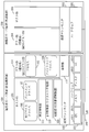
- FIG. 3 is a diagram illustrating an example of a system configuration according to the first embodiment. The figure which shows the flow of the general I / O process in a virtual environment.
- FIG. 3 is a diagram showing a flow of I / O processing according to the first embodiment.
- FIG. 3 is a flowchart showing an example of I / O request transfer processing according to the first embodiment.
- FIG. 3 is a flowchart showing an operation example of an I / O control unit according to the first embodiment.
- FIG. 3 is a flowchart showing an example of I / O response transfer processing according to the first embodiment.
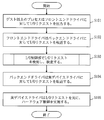
- FIG. 3 is a flowchart showing an operation example of an I / O control unit, a failure detection unit, and a synchronization unit according to the first embodiment.
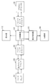
- FIG. 4 is a diagram illustrating a hardware configuration example of a server device according to the first to third embodiments.
- Embodiment 1 In the present embodiment, in a configuration in which an active server device and a standby server device are arranged, an active host OS or virtual machine is not added to the active guest OS without adding a failure detection mechanism.
- the monitor detects a hardware failure, discards the failure information related to the hardware failure, and prevents the hardware failure information from being propagated to the active guest OS. In this way, the operating guest OS is prevented from recognizing a hardware failure.
- the synchronous data for notifying the status of the active guest OS and the instruction data for instructing the standby guest OS to take over the operation of the active guest OS are subsequently sent from the active server device. Is output to the standby server device. Then, the standby server device uses the synchronization data to make the state of the standby guest OS the same as the state of the active guest OS without being affected by the hardware failure in the active server device. The standby guest OS normally takes over the operation of the active guest OS.
- FIG. 1 shows a system configuration according to the present embodiment.
- the server apparatus 100 and the server apparatus 200 are connected by a LAN (Local Area Network) 300.
- the server apparatus 100 and the server apparatus 200 are different physical computer apparatuses.
- the description will proceed with an example in which the server device 100 is an active server device and the server device 200 is a standby server device.
- the server device 100 is an example of a computer device
- the server device 200 is an example of an external device.
- the fact that the server device 100 is an example of a computer device is expressed as an active server device (computer device), and the fact that the server device 200 is an example of an external device is a standby server device (external device). It expresses.
- the hardware 101 includes, for example, a CPU (Central Processing Unit) 1011, a memory 1012, a disk 1013, and a NIC (Network Interface Card) 1014. Note that the hardware 101 may include other hardware elements.
- a virtual machine monitor 102 operates on the hardware 101, and a host OS 103 and a guest OS 104 operate on the virtual machine monitor 102.
- the guest OS 104 operates using virtual hardware (virtual CPU, virtual memory, virtual disk, virtual NIC, etc.) provided by a virtual machine realized by the virtual machine monitor 102 and the host OS 103.
- the guest OS is an example of a first guest OS.
- the guest OS 104 is an example of the first guest OS, and is shown in parentheses.
- the status of the active guest OS 104 (the context of the guest OS 104) is I / O (Input / Output).
- the server 109 is notified to the standby server device 200 by the synchronization unit 109 at every processing or at a constant cycle, and the guest OS 204 is synchronized with the guest OS 104 (the state of the guest OS 104 and the state of the guest OS 204 match) .
- the guest OS 204 is a guest OS that performs the same operation as the guest OS 104, and is an example of a second guest OS. In FIG. 1, parentheses indicate that the guest OS 204 is an example of a second guest OS.
- synchronization data Data that notifies the latest state of the guest OS 104 is referred to as synchronization data.
- the difference between the synchronization data and the state indicated in the previous synchronization data is indicated.
- the guest OS 204 each time new synchronization data is input, the previous synchronization data is overwritten with the new synchronization data. That is, there is only one synchronization data.
- the synchronization unit 109 operates across the virtual machine monitor 102 and the host OS 103.
- I / O requests include reading data from the disk 1013, writing data to the disk 1013, sending data to the network via the NIC 1014, and receiving data from the network via the NIC 1014.
- the I / O request is a request from the guest OS 104 to the hardware 101. Further, an I / O response from the hardware 101 described later to the guest OS 104 is a response from the hardware 101 to the request.
- the flow of I / O processing in the virtual environment is as shown in FIG. 2, and an I / O request from the process 105 is passed to the front-end driver 106 on the guest OS 104 and passes through the virtual machine monitor 102.
- the back-end driver 107 on the host OS 103 passes the I / O request to the real device driver 108, and the real device driver 108 executes the I / O request to the actual hardware 101.
- the I / O response processed by the hardware is returned to the real device driver 108, and the front end driver on the guest OS 104 passes from the real device driver 108 via the back end driver 107 on the host OS 103 and the virtual machine monitor 102. 106, and returned to the process 105 that issued the I / O request.
- an I / O control unit 110 that controls I / O requests and I / O responses between the front-end driver 106 and the back-end driver 107 is arranged on the host OS 103.
- a failure detection unit 111 for inspecting whether or not there is a failure with respect to the I / O response detected by the I / O control unit 110 is arranged.
- a storage unit 112 that temporarily stores a copy of the I / O request from the guest OS 104 is arranged on the virtual machine monitor 102.
- the I / O control unit 110 inputs an I / O request from the front-end driver 106, copies the input I / O request, and copies the I / O request.
- the data is stored in the storage unit 112 and an I / O request is output to the backend driver 107.
- the virtual machine monitor 102 stores a copy of the I / O request from the I / O control unit 110 in a physical storage area associated with the storage unit 112.
- the virtual machine monitor 102 stores a copy of the I / O request in a predetermined address of the memory 1012 or a register of the CPU 1011. Thereafter, as in the case of FIG.
- the I / O request reaches the hardware 101 from the back-end driver 107 via the real device driver 108.
- the hardware 101 outputs an I / O response that is a response to the I / O request to the real device driver 108, and the I / O control unit 110 inputs the I / O response from the back-end driver 107.
- the I / O control unit 110 outputs the input I / O response to the failure detection unit 111.
- the failure detection unit 111 inputs an I / O response from the I / O control unit 110, examines the input I / O response, and if an error message exists in the I / O response, If it is determined that a failure has occurred, the I / O response is discarded, and if there is no error message in the I / O response, the I / O response is forwarded via the I / O control unit 110. Output to the end driver 106. Since the error message of the I / O response is a message for notifying a failure in the hardware 101, when the failure detection unit 111 detects an error message from the I / O response, a failure has occurred in the hardware 101.
- the failure detection unit 111 issues a synchronization instruction to the synchronization unit 109 when a failure of the hardware 101 is detected by detecting an error message of the I / O response.
- the synchronization unit 109 acquires a copy of the I / O request from the storage unit 112 in accordance with the synchronization instruction from the failure detection unit 111, and the guest OS 104 at the time when the failure of the hardware 101 is detected by the failure detection unit 111.
- Information indicating the state is generated.
- Information indicating the state of the guest OS 104 includes the process name of the process 105, the value of the programmable counter of the CPU 1011, the value of the storage area of the memory 1012 allocated to the guest OS 104, and the like.
- the synchronization unit 109 outputs a copy of the I / O request and information indicating the state of the guest OS 104 at the time when the failure of the hardware 101 is detected to the server apparatus 200 as synchronization data.
- the synchronization unit 109 outputs an instruction message that instructs the guest OS 204 to take over the operation performed by the guest OS 104 to the server device 200. Thereafter, in the server device 200, the guest OS 204 becomes the active system and takes over the operation of the guest OS 104.
- the failure detection unit 111 checks the I / O response before the I / O response reaches the guest OS 104, determines whether or not a failure has occurred in the hardware 101, and the failure has occurred in the hardware 101.
- Control is performed so that the I / O response does not reach the guest OS 104 when it occurs. Therefore, the state of the guest OS 104 notified to the guest OS 204 is a state before the detection of the hardware 101 failure, and the guest OS 204 can take over the operation of the guest OS 104 from the state before the detection of the hardware 101 failure.
- the synchronization unit 109 is an example of a takeover control unit
- the I / O control unit 110 is an example of a request management unit.
- the synchronization unit 109 is an example of a takeover control unit and is expressed as a synchronization unit (takeover control unit)
- the I / O control unit 110 is an example of a request management unit (I / O control unit ( Request management department).
- the synchronization unit 109, the I / O control unit 110, and the failure detection unit 111 are programs that operate on the virtual machine monitor 102 or the host OS 103.
- the programs of the synchronization unit 109, the I / O control unit 110, and the failure detection unit 111 are stored in the disk 1013 before execution, and are loaded from the disk 1013 to the memory 1012 and executed by the CPU 1011 before execution.
- the above-described operation is performed.
- the server device 200 has a module configuration example similar to that of the server device 100.
- FIGS. 4 to 7 a series of flow from I / O request generation from the process 105 on the guest OS 104 to I / O response inspection and processing after I / O response inspection. Will be explained. 4 and 5 show the flow of the I / O request transfer process from the process 105 on the guest OS 104 to the hardware 101, and FIGS. 6 and 7 show the process 105 on the guest OS 104 from the hardware 101. The flow of the transfer process of the I / O response to is shown.
- FIG. 4 and FIG. 5 will be described.
- the process 105 on the guest OS 104 outputs an I / O request to the front end driver 106 (S101).
- the front end driver 106 transfers the received I / O request to the back end driver 107 on the host OS 103 via the virtual machine monitor 102 (S102).
- the I / O control unit 110 on the host OS 103 detects the I / O request and performs the processing shown in FIG. 5 (S103).
- the I / O control unit 110 acquires an I / O request from the front-end driver 106, copies the acquired I / O request, outputs a copy of the I / O request to the storage unit 112, and stores the storage unit 112. A copy of the I / O request is stored in (S1031). Next, the I / O control unit 110 transfers the I / O request to the back-end driver 107 of the host OS 103 (S1032).
- the back-end driver 107 receives an I / O request from the I / O control unit 110, and transfers the input I / O request to the real device driver 108 (S104).
- the actual device driver 108 executes control of the hardware 101 based on the I / O request (S105).
- the hardware 101 returns an I / O response to the real device driver 108 on the host OS 103 (S201).
- the actual device driver 108 transfers the received I / O response to the back-end driver 107 (S202).
- the back-end driver 107 transfers the I / O response to the front-end driver 106 on the guest OS 104 (S203).
- the I / O control unit 110 on the host OS 103 detects an I / O response and performs the process shown in FIG. 7 (S204).
- the I / O control unit 110 acquires an I / O response from the back-end driver 107, and transfers the acquired I / O response to the failure detection unit 111 (S2041).
- the failure detection unit 111 inputs an I / O response from the I / O control unit 110 and checks whether there is an error message in the input I / O response (S2042). If the error message is not included in the I / O response, and therefore no failure has occurred in the hardware 101 (NO in S2043), the failure detection unit 111 directly controls the I / O response as I / O control.
- the I / O control unit 110 transfers the I / O response to the front end driver 106 on the guest OS 104 (S2044).
- the I / O control unit 110 deletes the I / O request stored in the storage unit 112 and ends the process (S2045). Then, the front-end driver 106 on the guest OS 104 returns an I / O response to the process 105 (S205).
- an error message is included in the I / O response. For this reason, if a failure has occurred in the hardware 101 (YES in S2043), the failure detection unit 111 has detected the error message. And a synchronization instruction is output to the synchronization unit 109 (S2046).
- the synchronization unit 109 acquires the I / O request stored in the storage unit 112 in S1031 of FIG. 5 from the storage unit 112, and generates information for notifying the state of the active guest OS 104.
- the information for notifying the status of the I / O request and the guest OS 104 becomes the synchronization data, and the synchronization unit 109 transmits the synchronization data to the server device 200 and receives an instruction message instructing the guest OS 204 to take over the operation of the guest OS 104. It transmits to the server apparatus 200 (S2047). As described above, the state of the guest OS 104 immediately before the failure of the hardware 101 is propagated to the guest OS 104 is notified to the server device 200, and the guest OS 204 immediately before the failure of the hardware 101 is propagated to the guest OS 104.
- the synchronization unit 109 forcibly stops the guest OS 104 of the active server device 100 after the synchronization is completed (after transmission of the synchronization data and the instruction message), and takes over the operation of the guest OS 104 to the guest OS 204 on the standby server device 200. (S2048). At this point, the operation of the guest OS 104 is resumed by the guest OS 204 on the synchronization-destination standby server apparatus 200, and the processing is continued without inheriting a hardware failure in the entire system.
- the standby guest OS when a failure occurs in the active hardware, the standby guest OS is synchronized with the state immediately before the hardware failure is propagated to the active guest OS. Can do. As a result, the operation performed on the active guest OS can be normally transferred to the standby guest OS without being affected by the hardware failure of the active system, and the process is smoothly switched to the standby system. be able to. Further, according to the present embodiment, there is an advantage that only one synchronization data is managed. Furthermore, according to the present embodiment, there is an advantage that a mechanism for detecting a hardware failure is unnecessary on the guest OS.
- the I / O control unit 110 and the failure detection unit 111 are included in the host OS, but the I / O control unit 110 and the failure detection unit 111 are included in the virtual machine monitor 102. Good. Further, a configuration in which the I / O control unit 110 is included in the host OS 103 and the failure detection unit 111 is included in the virtual machine monitor 102 may be employed. Further, the I / O control unit 110 may be included in the virtual machine monitor 102, and the failure detection unit 111 may be included in the host OS 103.
- the operating state of the active guest OS is synchronized with the standby server using the virtual environment, and a hardware failure occurs in the active server
- the hardware processing on the guest OS is performed via the virtual machine monitor, the hardware failure is detected by the host OS or the virtual machine monitor, and the hardware failure information is displayed.
- Embodiment 2 The failure detection unit 111 according to the first embodiment detects a failure of the hardware 101 by checking whether there is no error message regarding the I / O response. On the other hand, the failure detection unit 111 may periodically check whether the hardware has no failure or the hardware is operating normally independently of the I / O response. In addition, the failure detection unit 111 checks whether there is a hardware failure or whether the hardware is operating normally when an I / O request from the front-end driver 106 arrives at the I / O control unit 110. You may do it. When a hardware failure is detected, the operations after S2046 in FIG. 7 described in the first embodiment are performed.
- a hardware failure inspection / operation confirmation method by the failure detection unit 111 there are a method of performing communication confirmation by ping or the like regarding the network, and a method of inspecting the NIC up / down.
- the disc for example, S.M. M.M. A. R. T.A. (Self-Monitoring, Analysis and Reporting Technology)
- IPMI Intelligent Platform Management Interface
- the failure detection unit 111 periodically checks for a failure in the hardware 101, a copy of the I / O request may not be stored in the storage unit 112 when the failure in the hardware 101 is detected. If the copy of the I / O request is not stored in the storage unit 112, the synchronization unit 109 synchronizes information indicating the state of the guest OS 104 at the time when the failure of the hardware 101 is detected in S2047 of FIG. The data is output to the server device 200 as data. On the other hand, when a copy of the I / O request is stored in the storage unit 112, the synchronization unit 109 indicates information indicating the state of the guest OS 104 when a failure of the hardware 101 is detected in S2047 of FIG.
- a copy of the I / O request is output to the server device 200 as synchronization data.
- the synchronization unit 109 uses the server apparatus 200 as a synchronous data copy of the I / O request together with information indicating the state of the guest OS 104 at the time when the failure of the hardware 101 is detected in S2047 of FIG. Output to.
- the system configuration according to the present embodiment is also as shown in FIG.
- the standby guest OS is returned to the state immediately before the hardware failure is propagated to the active guest OS. Can be synchronized. As a result, the operation performed on the active guest OS can be normally transferred to the standby guest OS without being affected by the hardware failure of the active system, and the process is smoothly switched to the standby system. be able to. Further, according to the present embodiment, it is possible to detect a hardware failure at a stage where an I / O request is made, and it is possible to detect a hardware failure earlier than in the first embodiment.
- the hardware I / O processing on the guest OS is performed via the virtual machine monitor or the host OS, and the I / O from the guest OS on the host OS or the virtual machine monitor is used. Keep your request temporarily,
- the host OS or virtual machine monitor detects a failure related to hardware I / O, and before the failure information related to the hardware I / O is notified to the guest OS, the host OS or virtual Discard failure information related to hardware I / O on the machine monitor,
- the operating state in which the guest OS issued an I / O request is synchronized with the standby system, and the synchronization data is used to cause a failure on the standby server device.
- the virtual environment synchronization system has been described in which the guest OS can be continuously operated by resuming the operation of the guest OS immediately before the occurrence of the error.
- Embodiment 3 In the first embodiment, a flow from the occurrence of hardware failure to system switching in a system in which one guest OS is arranged in each server device is shown. However, there are a plurality of guest OSs to be synchronized by the software FT. Also good. In other words, the present embodiment targets a system in which two or more guest OSs are arranged in the active server device and a guest OS corresponding to each guest OS in the active server device is arranged in the standby server device. . When a failure occurs in the hardware of the active server device, the synchronization unit of the active server device outputs synchronization data to the standby server device for each guest OS.
- the standby server device takes over the operation of the active guest OS by synchronizing each guest OS with the state of the active guest OS immediately before the failure of the active hardware based on the synchronization data. Make it.
- the storage unit 112 shown in the first embodiment is prepared for each guest OS, and when an error message is detected in the I / O response, the synchronization unit 109 starts from the storage unit 112 for each guest OS. An I / O request for each guest OS is acquired, and synchronization data and instruction data are output for each guest OS.
- the failure detection unit 111 detects a failure of the hardware 101 by a periodic inspection, or when an I / O request reaches the I / O control unit 110.
- the synchronization unit 109 acquires an I / O request for each guest OS from the storage unit 112 for each guest OS, and for each guest OS Synchronous data and instruction data are output. Other operations are as described in the first embodiment and the second embodiment, and a description thereof will be omitted.
- the standby guest OS can be synchronized with the state immediately before the hardware failure is propagated to the active guest OS. it can.
- the standby guest OS can normally take over the operations performed on the active guest OS without being affected by the hardware failure of the active system. And the process can be smoothly switched to the standby system.
- FIG. 8 is a diagram illustrating an example of hardware resources of the server apparatuses 100 and 200 described in the first to third embodiments.
- the configuration in FIG. 8 is merely an example of the hardware configuration of the server apparatuses 100 and 200, and the hardware configuration of the server apparatuses 100 and 200 is not limited to the configuration illustrated in FIG. There may be.
- the server apparatuses 100 and 200 include a CPU 911 (also referred to as a central processing unit, a central processing unit, a processing unit, an arithmetic unit, a microprocessor, a microcomputer, and a processor) that executes a program.
- the CPU 911 receives, for example, a ROM (Read Only Memory) 913, a RAM (Random Access Memory) 914, a communication board 915, a display device 901, a keyboard 902, a mouse 903, a magnetic disk device 920, and a scanner device 907 via a bus 912. Connected and controls these hardware devices.
- the CPU 911 may be connected to an FDD 904 (Flexible Disk Drive), a compact disk device 905 (CDD), and a printer device 906.
- FDD 904 Flexible Disk Drive
- CDD compact disk device
- printer device 906 a storage device such as an optical disk device or a memory card (registered trademark) read / write device may be used.
- the RAM 914 is an example of a volatile memory.
- the storage media of the ROM 913, the FDD 904, the CDD 905, and the magnetic disk device 920 are an example of a nonvolatile memory. These are examples of the storage device.
- a communication board 915, a keyboard 902, a mouse 903, an FDD 904, a scanner device 907, and the like are examples of input devices.
- the communication board 915, the display device 901, the printer device 906, and the like are examples of output devices.
- the communication board 915 is connected to the LAN 300 as shown in FIG.
- the communication board 915 can be connected to, for example, the Internet, a WAN (wide area network), or the like.
- the magnetic disk device 920 stores a virtual machine monitor 921, a host OS 922, a program group 923, and a file group 924.
- the programs in the program group 923 are executed by the CPU 911, the virtual machine monitor 921, and the host OS 922.
- the virtual machine monitor 921 itself includes the function of the host OS 922 or the virtual machine monitor 921 exists in the host OS 922.
- the ROM 913 stores a BIOS (Basic Input Output System) program
- the magnetic disk device 920 stores a boot program.
- BIOS Basic Input Output System
- the server devices 100 and 200 are activated, the BIOS program in the ROM 913 and the boot program in the magnetic disk device 920 are executed, and the virtual machine monitor 921 and the host OS 922 are activated by the BIOS program and the boot program.
- the program group 923 includes programs for realizing the synchronization unit 109, the I / O control unit 110, and the failure detection unit 111 described in the first to third embodiments.
- the file group 924 includes “Judgment of”, “Examination of”, “Detection of”, “Synchronization of”, “Check of”, “ Information, data, signal values, variable values, and parameters that indicate the results of the processing described as “control of”, “setting of”, “selection of”, etc. It is stored as an item.
- the “ ⁇ file” and “ ⁇ database” are stored in a recording medium such as a disk or a memory.
- Information, data, signal values, variable values, and parameters stored in a storage medium such as a disk or memory are read out to the main memory or cache memory by the CPU 911 via a read / write circuit, and extracted, searched, referenced, compared, and calculated.
- the data and signal values are the RAM 914 memory, the FDD 904 flexible disk, the CDD 905 compact disk, and the magnetic field. Recording is performed on a recording medium such as a magnetic disk of the disk device 920, other optical disks, mini disks, DVDs, and the like. Data and signals are transmitted online via a bus 912, signal lines, cables, or other transmission media.
- what is described as “to part” in the description of the first to third embodiments may be “to step”, “to procedure”, and “to process”. That is, what is described as “ ⁇ unit” may be realized by firmware stored in the ROM 913. Alternatively, it may be implemented only by software, or only by hardware such as elements, devices, substrates, and wirings, by a combination of software and hardware, or by a combination of firmware.
- Firmware and software are stored as programs in a recording medium such as a magnetic disk, a flexible disk, an optical disk, a compact disk, a mini disk, and a DVD.
- the program is read by the CPU 911 and executed by the CPU 911. In other words, the program causes the computer to function as the “unit” in the first to third embodiments. Alternatively, the computer executes the procedure and method of “unit” in the first to third embodiments. It is also possible to grasp the operations of the server apparatuses 100 and 200 described in the first to third embodiments as, for example, a data processing method.
- the server devices 100 and 200 described in the first to third embodiments include a CPU as a processing device, a memory as a storage device, a magnetic disk, a keyboard as an input device, a mouse, a communication board, and a display device as an output device, A computer provided with a communication board or the like, and implements the functions indicated as “ ⁇ units” using the processing device, storage device, input device, and output device as described above.
- server device 101 hardware, 102 virtual machine monitor, 103 host OS, 104 guest OS, 105 process, 106 front end driver, 107 back end driver, 108 real device driver, 109 synchronization unit, 110 I / O control unit, 111 failure detection unit, 112 storage unit, 200 server device, 201 hardware, 202 virtual machine monitor, 203 host OS, 204 guest OS, 300 LAN, 1011 CPU, 1012 memory, 1013 disk, 1014 NIC.
Landscapes
- Engineering & Computer Science (AREA)
- Theoretical Computer Science (AREA)
- Software Systems (AREA)
- Physics & Mathematics (AREA)
- General Engineering & Computer Science (AREA)
- General Physics & Mathematics (AREA)
- Quality & Reliability (AREA)
- Hardware Redundancy (AREA)
Abstract
Selon l'invention, une unité de commande d'entrée/sortie (110) reçoit en entrée une requête d'entrée/sortie d'un système d'exploitation invité (104), et stocke une copie de la requête d'entrée/sortie dans une unité de stockage (112). Lorsqu'un matériel (101) délivre une réponse d'entrée/sortie à la requête d'entrée/sortie, une unité de détection de défaut (111) inspecte la réponse d'entrée/sortie. S'il existe un message d'erreur dans la réponse d'entrée/sortie, l'unité d'entrée/sortie détermine qu'un défaut s'est produit dans le matériel (101), détruit la réponse d'entrée/sortie et exécute une instruction de synchronisation dans une unité de synchronisation (109). L'unité de synchronisation (109) délivre à un dispositif serveur (200) la copie de la requête d'entrée/sortie présente dans l'unité de stockage (112) et des informations indiquant l'état du système d'exploitation invité (104) au moment où le défaut dans le matériel (101) a été détecté. Sur le dispositif serveur (200), un système d'exploitation invité (204) est mis dans le même état que le système d'exploitation invité (104), et le système d'exploitation invité (204) prend la suite d'une opération pour le système d'exploitation invité (104) sur la base des informations provenant de l'unité de synchronisation (109).
Priority Applications (2)
| Application Number | Priority Date | Filing Date | Title |
|---|---|---|---|
| PCT/JP2010/070812 WO2012070102A1 (fr) | 2010-11-22 | 2010-11-22 | Dispositif informatique et programme |
| JP2012545548A JP5335150B2 (ja) | 2010-11-22 | 2010-11-22 | 計算機装置及びプログラム |
Applications Claiming Priority (1)
| Application Number | Priority Date | Filing Date | Title |
|---|---|---|---|
| PCT/JP2010/070812 WO2012070102A1 (fr) | 2010-11-22 | 2010-11-22 | Dispositif informatique et programme |
Publications (1)
| Publication Number | Publication Date |
|---|---|
| WO2012070102A1 true WO2012070102A1 (fr) | 2012-05-31 |
Family
ID=46145479
Family Applications (1)
| Application Number | Title | Priority Date | Filing Date |
|---|---|---|---|
| PCT/JP2010/070812 Ceased WO2012070102A1 (fr) | 2010-11-22 | 2010-11-22 | Dispositif informatique et programme |
Country Status (2)
| Country | Link |
|---|---|
| JP (1) | JP5335150B2 (fr) |
| WO (1) | WO2012070102A1 (fr) |
Cited By (2)
| Publication number | Priority date | Publication date | Assignee | Title |
|---|---|---|---|---|
| JP6242557B1 (ja) * | 2017-03-21 | 2017-12-06 | 三菱電機株式会社 | 制御装置および制御プログラム |
| EP3608784A1 (fr) * | 2018-08-10 | 2020-02-12 | Yokogawa Electric Corporation | Système et appareil de commande |
Families Citing this family (1)
| Publication number | Priority date | Publication date | Assignee | Title |
|---|---|---|---|---|
| JP2017045084A (ja) * | 2015-08-24 | 2017-03-02 | 日本電信電話株式会社 | 障害検知装置及び障害検知方法 |
Citations (2)
| Publication number | Priority date | Publication date | Assignee | Title |
|---|---|---|---|---|
| JP2008107896A (ja) * | 2006-10-23 | 2008-05-08 | Nec Corp | 物理資源制御管理システム、物理資源制御管理方法および物理資源制御管理用プログラム |
| JP2009245216A (ja) * | 2008-03-31 | 2009-10-22 | Toshiba Corp | 情報処理装置および障害回復方法 |
Family Cites Families (2)
| Publication number | Priority date | Publication date | Assignee | Title |
|---|---|---|---|---|
| JP4544146B2 (ja) * | 2005-11-29 | 2010-09-15 | 株式会社日立製作所 | 障害回復方法 |
| JP2009080692A (ja) * | 2007-09-26 | 2009-04-16 | Toshiba Corp | 仮想計算機システム及び同システムにおけるサービス引き継ぎ制御方法 |
-
2010
- 2010-11-22 JP JP2012545548A patent/JP5335150B2/ja not_active Expired - Fee Related
- 2010-11-22 WO PCT/JP2010/070812 patent/WO2012070102A1/fr not_active Ceased
Patent Citations (2)
| Publication number | Priority date | Publication date | Assignee | Title |
|---|---|---|---|---|
| JP2008107896A (ja) * | 2006-10-23 | 2008-05-08 | Nec Corp | 物理資源制御管理システム、物理資源制御管理方法および物理資源制御管理用プログラム |
| JP2009245216A (ja) * | 2008-03-31 | 2009-10-22 | Toshiba Corp | 情報処理装置および障害回復方法 |
Non-Patent Citations (1)
| Title |
|---|
| YOSHIAKI TAMURA ET AL.: "Kemari: Virtual Machine Synchronization for Fault Tolerance", TRANSACTIONS OF INFORMATION PROCESSING SOCIETY OF JAPAN TRANSACTION, vol. 3, no. 1, 15 April 2010 (2010-04-15), pages 13 - 24 * |
Cited By (3)
| Publication number | Priority date | Publication date | Assignee | Title |
|---|---|---|---|---|
| JP6242557B1 (ja) * | 2017-03-21 | 2017-12-06 | 三菱電機株式会社 | 制御装置および制御プログラム |
| WO2018173123A1 (fr) * | 2017-03-21 | 2018-09-27 | 三菱電機株式会社 | Dispositif de commande et programme de commande |
| EP3608784A1 (fr) * | 2018-08-10 | 2020-02-12 | Yokogawa Electric Corporation | Système et appareil de commande |
Also Published As
| Publication number | Publication date |
|---|---|
| JP5335150B2 (ja) | 2013-11-06 |
| JPWO2012070102A1 (ja) | 2014-05-19 |
Similar Documents
| Publication | Publication Date | Title |
|---|---|---|
| JP5851503B2 (ja) | 高可用性仮想機械環境におけるアプリケーションの高可用性の提供 | |
| US9262257B2 (en) | Providing boot data in a cluster network environment | |
| US8984330B2 (en) | Fault-tolerant replication architecture | |
| CN105683919B (zh) | 用于安全关键软件应用的多核处理器故障检测 | |
| US7496786B2 (en) | Systems and methods for maintaining lock step operation | |
| US20150278046A1 (en) | Methods and systems to hot-swap a virtual machine | |
| US10929234B2 (en) | Application fault tolerance via battery-backed replication of volatile state | |
| US10185636B2 (en) | Method and apparatus to virtualize remote copy pair in three data center configuration | |
| JP5392594B2 (ja) | 仮想計算機冗長化システム、コンピュータシステム、仮想計算機冗長化方法、及びプログラム | |
| JP2012221321A (ja) | フォールトトレラント計算機システム、フォールトトレラント計算機システムの制御方法、及びフォールトトレラント計算機システムの制御プログラム | |
| US11960366B2 (en) | Live migrating virtual machines to a target host upon fatal memory errors | |
| US20060259815A1 (en) | Systems and methods for ensuring high availability | |
| US7530000B2 (en) | Early detection of storage device degradation | |
| TWI592796B (zh) | 運用於雲端服務之虛擬機之封包察覺式容錯方法及系統、電腦可讀取之記錄媒體及電腦程式產品 | |
| WO2015033433A1 (fr) | Dispositif de stockage, et procédé d'identification d'emplacement de défaillance | |
| US20250225023A1 (en) | Server maintainability configuration method and apparatus, electronic device and storage medium | |
| CN105579973A (zh) | 冗余系统以及冗余系统管理方法 | |
| US9063854B1 (en) | Systems and methods for cluster raid data consistency | |
| US9798615B2 (en) | System and method for providing a RAID plus copy model for a storage network | |
| US10102088B2 (en) | Cluster system, server device, cluster system management method, and computer-readable recording medium | |
| JP5335150B2 (ja) | 計算機装置及びプログラム | |
| JP5440073B2 (ja) | 情報処理装置,情報処理装置の制御方法および制御プログラム | |
| JP2011100300A (ja) | 計算機装置及び情報処理方法及びプログラム | |
| JP5880608B2 (ja) | フォールトトレラントサーバ | |
| KR101564144B1 (ko) | 펌웨어 관리 장치 및 방법 |
Legal Events
| Date | Code | Title | Description |
|---|---|---|---|
| 121 | Ep: the epo has been informed by wipo that ep was designated in this application |
Ref document number: 10860094 Country of ref document: EP Kind code of ref document: A1 |
|
| WWE | Wipo information: entry into national phase |
Ref document number: 2012545548 Country of ref document: JP |
|
| NENP | Non-entry into the national phase |
Ref country code: DE |
|
| 122 | Ep: pct application non-entry in european phase |
Ref document number: 10860094 Country of ref document: EP Kind code of ref document: A1 |