WO2012073436A1 - タイヤ - Google Patents
タイヤ Download PDFInfo
- Publication number
- WO2012073436A1 WO2012073436A1 PCT/JP2011/006363 JP2011006363W WO2012073436A1 WO 2012073436 A1 WO2012073436 A1 WO 2012073436A1 JP 2011006363 W JP2011006363 W JP 2011006363W WO 2012073436 A1 WO2012073436 A1 WO 2012073436A1
- Authority
- WO
- WIPO (PCT)
- Prior art keywords
- mark
- dots
- tire
- dot
- ground color
- Prior art date
- Legal status (The legal status is an assumption and is not a legal conclusion. Google has not performed a legal analysis and makes no representation as to the accuracy of the status listed.)
- Ceased
Links
Images


Classifications
-
- B—PERFORMING OPERATIONS; TRANSPORTING
- B60—VEHICLES IN GENERAL
- B60C—VEHICLE TYRES; TYRE INFLATION; TYRE CHANGING; CONNECTING VALVES TO INFLATABLE ELASTIC BODIES IN GENERAL; DEVICES OR ARRANGEMENTS RELATED TO TYRES
- B60C13/00—Tyre sidewalls; Protecting, decorating, marking, or the like, thereof
- B60C13/001—Decorating, marking or the like
-
- Y—GENERAL TAGGING OF NEW TECHNOLOGICAL DEVELOPMENTS; GENERAL TAGGING OF CROSS-SECTIONAL TECHNOLOGIES SPANNING OVER SEVERAL SECTIONS OF THE IPC; TECHNICAL SUBJECTS COVERED BY FORMER USPC CROSS-REFERENCE ART COLLECTIONS [XRACs] AND DIGESTS
- Y10—TECHNICAL SUBJECTS COVERED BY FORMER USPC
- Y10T—TECHNICAL SUBJECTS COVERED BY FORMER US CLASSIFICATION
- Y10T152/00—Resilient tires and wheels
- Y10T152/10—Tires, resilient
- Y10T152/10495—Pneumatic tire or inner tube
Definitions
- the present invention relates to a tire that can be a pneumatic tire or a solid tire provided with a mark formed by printing on the outer surface of the side portion, and in particular, a mark that becomes a printed layer accompanying the use of the tire.
- the present invention proposes a technique for effectively preventing the occurrence of cracks in the chapter and peeling of the mark forming portion and maintaining the visibility of the mark high over a long period of time.
- the company name, brand name, tire size, production time, etc. on the outer surface of the side part including the sidewall part and bead part of the tire are marked by a mark made up of symbols, patterns including characters, figures, barcodes, etc. Display is widely done.
- a mark is generally formed by, for example, solid coating by printing, coloring rubber, painting to be applied with paint, or a sticker attached.
- the tread tread is elastically deformed by receiving a contact pressure from the road surface during load rolling of the tire, for example, the sidewall portion and the bead portion of the pneumatic tire are also elastically deformed.
- the mark itself is There was a risk of deformation and wrinkling or cracking in the printed layer or the like, or the printed layer or the like peeled off from the outer surface of the side part.
- the visibility of the mark attached to the pneumatic tire is impaired, and a predetermined information transmission function or the like by the mark cannot be sufficiently exhibited over a long period of time.
- An object of the present invention is to solve such problems of the prior art, and the object of the present invention is, for example, by elastic deformation of a sidewall portion and a bead portion of a pneumatic tire. Even if tensile and compressive deformation occurs on the outer surface of the part, cracks in the mark formed on the outer surface of the side part, peeling of the mark forming part, etc. are effectively prevented, and the visibility of the mark is increased. It is in providing the tire which can fully be demonstrated over a period.
- the tire of the present invention has a plurality of dots of the same contour shape independent from each other, having a color different from the ground color of the outer surface of the side portion on the outer surface of the side portion of the tire that can be a pneumatic tire or a solid tire A mark formed by printing is provided.
- the term “same contour shape” includes not only the case of literally the same contour shape but also the case of having a similar contour shape.
- the size of a dot to be printed is changed, and the mark is shaded, or at least a part of the mark is printed. Change the density and add shade to the mark.
- At least one of the hue and saturation of the dot is changed in at least a part of the mark.
- the outline shape of the dot is a polygon, and the mark is formed by the dot and a ground color gap portion on the outer surface of the side portion formed between the dots.
- the maximum surface area of the dots is 50 mm 2 or the ratio of the length of the shortest portion to the length of the longest portion of the maximum unit dot is 1 ⁇ 2 or more. .
- the minimum ground color gap portion formed between dots that is, the maximum upper limit width of the minimum ground color gap portion between the largest unit dots having the largest surface area among the dots contributing to the formation of the mark. Is preferably 10% of the length of the shortest portion of the largest unit dot.
- the width of the character is 5 mm or more and the height of the character is 8 mm or more.
- the mark provided on the outer surface of the side portion is printed with a plurality of dots having the same contour shape independent from each other with ink having a color different from the ground color of the outer surface of the side portion.
- a mark composed of a plurality of printed dots and a ground color portion on the outer surface of the side portion existing between the dots can exhibit sufficient visibility. Since the dots forming the chapters exist independently from each other on the outer surface of the side portion, the compression and tensile deformation that occurs on the outer surface of the side portion when the tire rolls is a portion where there is no ink between the dots.
- the print area of each dot is sufficiently small, and the amount of each dot stretched due to compression and tensile deformation of the outer surface of the side part is sufficiently small. It is possible to suppress the occurrence of wrinkles and cracks on the mark due to the use of tires, and effectively prevents the mark forming part from peeling off from the outer surface of the side part. Can be maintained sufficiently high over a long period of time.
- the dot size is changed in at least a part of the mark, or the dot density is changed in at least a part of the mark, only the binary state of the presence / absence of dots is used.
- the color of the mark can be expressed, especially when the dot size and / or density is gradually changed in the desired direction of the mark. A gradation can be given, and thereby, desired visibility can be imparted to a mark formed by printing on a tire very easily.
- the hue and saturation of the dot when at least one of the hue and saturation of the dot is changed in at least a part of the mark, it is possible to easily realize a partial change in the hue or saturation of the mark itself. In this case, too, the gradation of the hue or saturation can be added by gradually changing the hue or saturation of the dots in the desired direction of the mark. Can be improved easily and more effectively.
- the ground color gap By dividing the mark by the part, the absolute amount of elastic deformation of the printed part that is deformed along with elastic deformation of the sidewall etc. is reduced, and the followability of the mark to the tire deformation is improved. Therefore, it is possible to more effectively prevent wrinkles, cracks, and peeling of the mark formation part on the printed layer of the mark, and reduce the ground color gap uniformly throughout the mark. And the visibility of the mark can be further improved.
- the ratio of the length of the shortest portion to the length of the longest portion of the maximum unit dot is set to 1/2 or more, for example, when the unit dot has a contour shape such as a rectangle or a square.
- the ratio of the short side length, etc., to the longest diagonal line is set to 1/2 or more, the total area of the dot print area is increased without increasing the ground color gap as much as possible. Therefore, it is possible to advantageously suppress an excessive increase in the ground color gap portion in response to a request for improving the visibility of the mark. In other words, if the above ratio is less than 1/2, the area of the ground color gap portion extending in the length direction of the longest portion becomes too large, and the visibility of the mark may be lowered.
- the set upper limit width of the minimum ground color gap portion formed between the dots is 10% of the length of the shortest portion of the maximum unit dot
- the outer surface of the side portion that is generally black It is possible to increase the brightness of the mark and the visibility while reducing the amount of exposure of the ground color.
- the mark formed by dot printing exhibits sufficient visibility. Can be made. In other words, if the width of the character is less than 5 mm and the height of the character is less than 8 mm, the character will be smaller, so it is less necessary to form the mark with dot printing in the first place. Further, there is a concern that the mark cannot be expressed sufficiently to the extent that the desired visibility can be exhibited by dot printing.
- the upper limit values of the width and height of the characters are determined depending on the type and size of the tire to which the present invention is applied, and are determined within the range of the space to which the mark is attached, and the preferable upper limit value is There is no particular.
- the outline shape of dots printed for forming a mark is a triangle.
- the outline shape of dots printed for forming a mark is a quadrangle. 6 illustrates another outline shape of dots printed to form a mark.
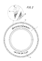
- reference numeral 1 in the drawing shows an outer surface of a side portion composed of a sidewall portion and a bead portion of the pneumatic tire, and the pneumatic tire of this embodiment has a tire on the side portion outer surface 1. It has a plurality of marks 2 and 3 for displaying a company name, a product name, etc., consisting of character strings along the circumferential direction.
- the side part surface 1 can be marked with a tire size or other marks.
- the marks 2 and 3 are enlarged, and the ground color (white in the drawing) of the side portion outer surface 1 and the ground color are shown. It is formed by printing with a color different from that (including a dot portion having black in the drawing). That is, in the tire shown in FIG. 1, the marks 2 and 3 are formed on the side portion outer surface 1 with a plurality of dots 4 having a rectangular contour shape such as a rhombus, independently of each other and having the same contour shape, and In this case, it is composed of a white, grid-like ground color gap portion 5 on the outer surface 1 of the side portion that is exposed to the outside between the dots 4.
- the compression and tensile deformation of the side portion outer surface 1 due to the rolling load of the tire causes parts of the marks 2 and 3 to be independent of each other.
- a large amount of ink is absorbed by the portion where the ink does not exist between the constituent dots 4, here the lattice-shaped ground color gap portion 5, while the printing is caused by compression and tensile deformation of the outer surface 1 of the side portion.
- the stretched amount or the like of the dot 4 itself is extremely small, cracks and wrinkles in the printed dot 4 of the marks 2 and 3 formed by gathering the dots 4 and a plurality of dots 4 together, It is possible to effectively prevent the separation of the dots 4 as the formation portions of the marks 2 and 3 from the side portion outer surface 1. As a result, the high visibility of the marks 2 and 3 can be sufficiently maintained over a long period of time.
- the color of the dot 4 is different from the ground color of the outer surface 1 of the side portion, for example, chromatic colors such as blue, red, and yellow, white, black, gray achromatic colors, and gloss It is possible to select from colors, fluorescent colors, or the like, or to superimpose a plurality of these colors.
- the dots 4 having rhombus outlines are arranged and arranged to form a grid-like ground color gap portion 5 between the dots 4. Since the form can be appropriately changed as required, the ground color gap portion 5 exposed to the outside between the dots 4 may not form a lattice shape depending on the arrangement form.
- the plurality of dots 4 constituting the marks 2 and 3 are all the same size. However, the size of the dots 4 can be appropriately selected as necessary. It is also possible to change the size and / or density of the dots 4 at least in part.
- the outline shape of the dots 4 is not limited to the quadrangle shown in FIG. 1, and can be various shapes.
- the contour shape of the dot 14 to be formed can be an ellipse, an oval, or the like in addition to a substantially circular shape.
- the density of the dots 14 forming the marks 12 and 13 is determined for each of the outer region and the inner region in the tire radial direction with respect to one or more characters constituting the character string along the tire circumferential direction.
- the gradation is added to the mark by gradually increasing it toward the central area.
- the density of the marks 12 and 13 can be expressed by changing the density of the dots 14 with one or more characters of the marks 12 and 13, the tire marks can be expressed. The visibility can be increased very easily. This also applies to the case where the dot size is gradually changed.
- the density of the dots 14 can be increased rapidly in at least a part of the marks 12 and 13. Although illustration is omitted, at least part of the mark can change the hue or saturation of the marks 12 and 13 by changing at least one of the hue and saturation of the dots. In this case, the marks 12 and 13 can be provided with gradations based on hue or saturation, for example.
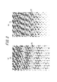
- FIG. 3 exemplifies a case where the outline shape of mutually independent dots printed for forming characters and other required marks is a triangle, and a plurality of triangles having the same outline shape including similar shapes A gradation is given by gradually decreasing the printing density of the dots 24 toward the lower side of the figure.
- the hatched portion indicates a printed portion of a dot having a required color
- the white portion or the like indicates a ground color gap portion 25 that is partitioned and formed between the dots 24.
- FIG. 3A shows a printing mode of a plurality of triangular dots in such a manner that the ground color gap portion 25 between the dots 24 is directed in the vertical direction and the diagonally horizontal direction in the drawing. It is a mode that extends linearly while gradually increasing the width dimension to the lower side, and the one shown in FIG. 3 (b) is a printing mode of a plurality of triangular dots between the printed dots 24.
- the ground color gap portion 25 extends linearly in the vertical direction of the figure, and extends in a zigzag manner between the two linear extension portions. Both the gap widths of the portion and the zigzag gap portion gradually increase toward the lower side of the figure.
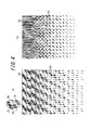
- each printed dot is a rectangle (rectangle), and the printing density of a plurality of square dots 24 of the same contour shape including similar shapes is gradually reduced toward the lower side of the figure. is there.
- the hatched portion in the drawing indicates a printed portion of dots having a required color
- the white portion or the like indicates a ground color gap portion 25 between the dots 24.
- the printing mode of the rectangular dots 24 is formed in a lattice shape in which the ground color gap portions 25 between the dots 24 extend perpendicularly to each other in the vertical and horizontal directions in the figure,
- the width of the ground color gap portion 25 is formed so as to gradually increase toward the lower side of the figure, and the place shown in FIG.
- the ground color gap portion 25 between the dots 24 extends in an obliquely linear manner in the upper right direction between a plurality of dots in the figure, and linearly in the upward direction in the figure.
- the continuous extension between a plurality of dots is blocked by adjacent dot rows, and the width of the ground color gap portion 25 is gradually increased toward the lower side of the figure. It will be.
- the maximum surface area of the mutually independent dots 4, 14, and 24 printed for the formation of the mark is 50 mm 2 regardless of the outline shape of the dots. Further, it is preferable for ensuring the required visibility while effectively preventing the occurrence of cracks and the like on the surfaces of the dots 4, 14, and 24.
- a rectangular dot 24 in FIG. in response to a request to reduce the ground color gap portions 5 and 25 as much as possible to ensure the improvement of the visibility of the mark, a rectangular dot 24 in FIG.
- the length l of the longest portion of the maximum unit dot is 1 (the short side length in the case of the illustrated dot 24 that forms a rectangle). Is set to 1/2 or more to suppress an unnecessary increase in the ground color gap portion 25 as much as possible.
- each of all the square dots 24 is The requirement of 1 / L ⁇ 1/2 is satisfied.
- the set upper limit width of the minimum ground color gap portion Cmin illustrated in FIG. 5 is the shortest of the maximum unit dots 24. It is preferable that the length is 10% of the length of the paddle portion (in the case of the dot 24 having a circular contour shape as shown in the drawing, the length of the longest portion and the length of the shortest portion are equal to each other).
- the width of the characters may be 5 mm or more and the height of the characters may be 8 mm or more. It is preferable for improving the visibility of characters formed by dot printing.
- the tire of the example is provided with a mark formed by printing a plurality of dots having the same contour shape independent of each other, having a color different from the ground color of the side portion outer surface on the side portion outer surface.
- the mark is formed by so-called solid printing.
- the size of the dots having a triangular outline shape is changed as shown in FIG. 3A, and in the tires 2 to 4, the maximum surface area of the dots is used as a parameter.
- the tires of Examples 5 to 7 have the above-mentioned parameters of 1 / L, and the tires of Examples 8 to 10 are the minimum ground described in connection with FIG.
- the upper limit width of the color gap portion Cmin is used as a parameter.
Landscapes
- Engineering & Computer Science (AREA)
- Mechanical Engineering (AREA)
- Tires In General (AREA)
- Tyre Moulding (AREA)
Abstract
Description
ここで、かかる標章は、たとえば、印刷によるベタ塗り、彩色ゴム、塗料の塗布になる塗装もしくは、貼着されたシール等によって形成することが一般的である。
そして、このことにより、空気入りタイヤに付した標章の視認性が損なわれて、標章による所定の情報伝達機能等を、長期間にわたって十分に発揮させることができなくなるという問題があった。
なおここで、「同一輪郭形状」とは、文字通り同一の輪郭形状を有する場合の他、相似の輪郭形状を有する場合をも含むものとする。
いいかえれば、上記の比が1/2未満では、最も長い部分の長さ方向に延びる地色隙間部分の面積が大きくなりすぎて標章の視認性が低下するうれいがある。
これを言い換えれば、文字の幅を5mm未満かつ、文字の高さを8mm未満とした場合は、文字が小さくなることから、そもそも標章を、ドットの印刷をもって形成することの必要性に乏しく、また、ドットの印刷では、標章を、所望の視認性を発揮し得る程度に十分に表現できない懸念がある。
なおここで、文字の幅及び高さの上限値は、この発明を適用するタイヤの種類やサイズによって異なる、標章を付するスペースの範囲内で決定されるものであり、好適な上限値は特に無い。
図1に示す実施形態において、図中1は、空気入りタイヤのサイドウォール部およびビード部からなるサイド部の外表面を示し、この実施形態の空気入りタイヤは、サイド部外表面1に、タイヤ周方向に沿う文字列からなる、会社名、商品名等の表示のための複数の標章2、3を有する。
なお、図示は省略するが、サイド部外表面1に付す標章としては、上述した文字のみならず、たとえば、図形、記号もしくは模様、またはこれらの組合せになるものとすることもでき、また、サイド部表面1には、タイヤサイズその他の標章を付することもできる。
すなわち、図1に示すタイヤでは、標章2、3を、サイド部外表面1上の、たとえば菱形等の四角形輪郭形状を有する、相互に独立したともに同一輪郭形状の複数のドット4と、それらのドット4間で外部に露出する、ここでは白色の、サイド部外表面1の格子状の地色隙間部分5とで構成している。
その結果として、標章2、3の高い視認性を、長期間にわたって十分に維持することができる。
またここでは、標章2、3を構成する複数のドット4をいずれも同一の大きさとしたが、ドット4の大きさは所要に応じて適宜選択することができ、また、標章2、3の少なくとも一部で、ドット4の大きさおよび/または密度を変化させることもできる。
このように、図示のタイヤでは、標章12、13の一文字以上で、ドット14の密度を変化させることにより、標章12、13の色の濃淡を表現することができるので、タイヤの標章の視認性を、極めて容易に高めることができる。
そしてこのことは、ドットの寸法を次第に変化させた場合にもまた同様である。
また、図示は省略するが、標章の少なくとも一部で、ドットの色相および彩度の少なくとも一方を変化させることによって、標章12、13の色相ないしは彩度の変化を表現することができ、この場合は、標章12、13に、たとえば色相ないしは彩度によるグラデーションをつけることもできる。
なお図3中、斜線部分は、所要の色彩をもつドットの印刷部分を示し、白色部分等は、ドット24間に区画形成される地色隙間部分25を示す。
なおこの図に示すところにおいてもまた、図中の斜線部分は、所要の色彩をもつドットの印刷部分を示し、白色部分等は、ドット24間の地色隙間部分25を示す。
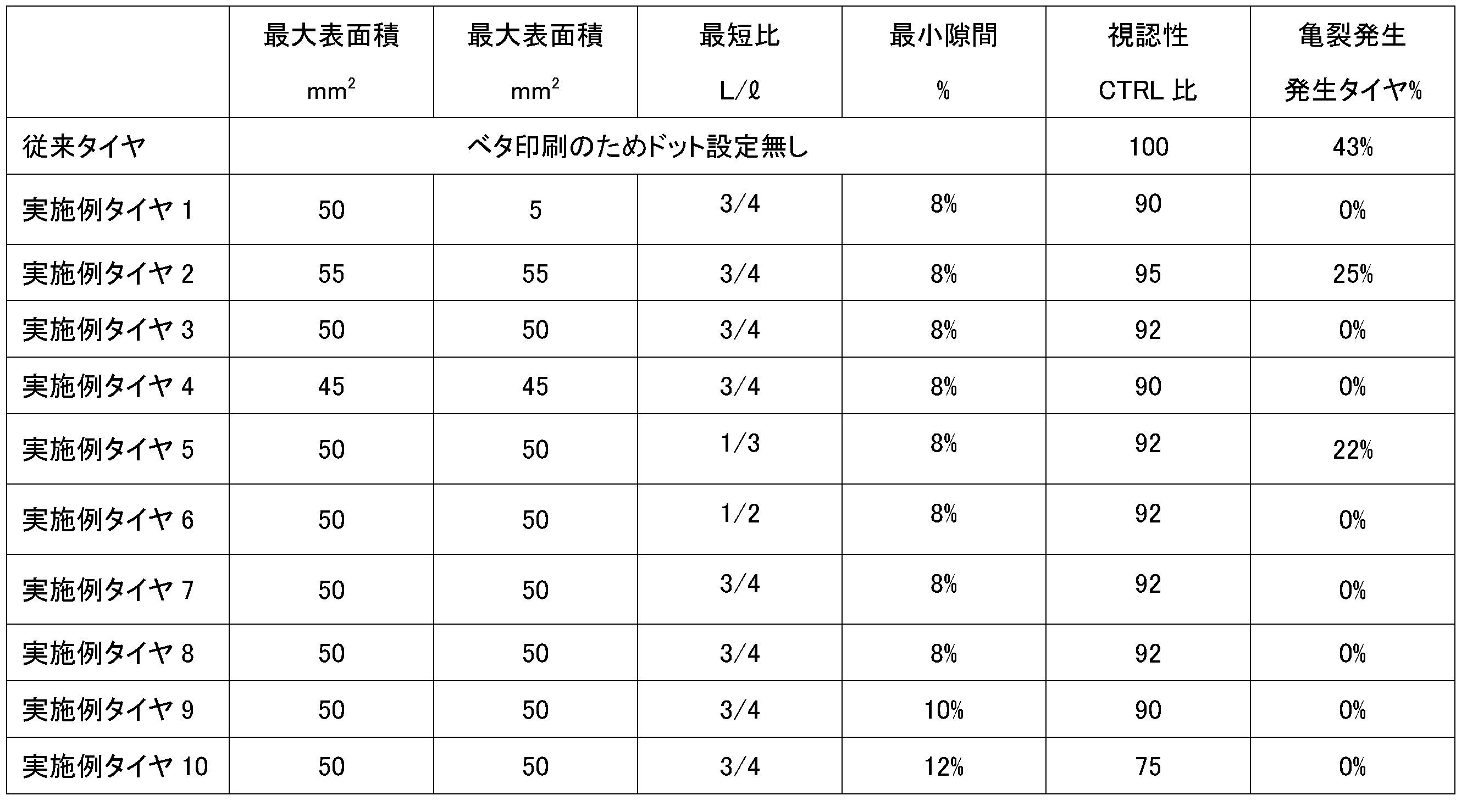
ここで、実施例タイヤは、サイド部外表面に、サイド部外表面の地色とは異なる色彩を有する、相互に独立した同一輪郭形状の複数のドットの印刷によって形成した標章を設けてなるものであり、従来タイヤは、標章をいわゆるベタ印刷によって形成したものである。
なお実施例タイヤ1は、輪郭形状が三角形をなすドットの大きさを図3(a)に示すように変化させたものであり、実施例タイヤ2~4は、ドットの最大表面積をパラメータとしたものであり、また、実施例タイヤ5~7は、先に述べたl/Lをパラメータとしたものであり、そして、実施例タイヤ8~10は、図5に関連させて述べた、最小地色隙間部分Cminの設定上限幅をパラメータとしたものである。
ところで、標章の視認性は、50人による感応評価を行い、はっきり読めるを100、なんとなく認識できるを50、全く見えないを0として無段階評価を行った。
また、亀裂の発生の有無については、一定本数(10本)を試作して移送テスト(10000km)を行い、亀裂の発生したタイヤの本数比率を求めることにより、評価した。
その結果を供試タイヤの諸元とともに表1に示す。
2、3、12、13 標章
4、14、24 ドット
5、25 地色隙間部分
Claims (9)
- タイヤのサイド部外表面に、サイド部外表面の地色とは異なる色彩を有する、相互に独立した同一輪郭形状の複数のドットの印刷により形成した標章を設けてなるタイヤ。
- 前記標章の少なくとも一部で、ドットの大きさを変化させて、標章に濃淡を付してなる請求項1に記載のタイヤ。
- 前記標章の少なくとも一部で、ドットの密度を変化させて、標章に濃淡を付してなる請求項1に記載のタイヤ。
- 前記標章の少なくとも一部で、ドットの色相および彩度の少なくとも一方を変化させてなる請求項1~3のいずれかに記載のタイヤ。
- 前記ドットの輪郭形状を多角形とし、前記標章を、前記ドットと、該ドット間に形成される、サイド部外表面の地色隙間部分とで形成してなる請求項1に記載のタイヤ。
- 前記ドットの最大表面積を50mm2としてなる請求項1~5のいずれかに記載のタイヤ。
- 最大単位ドットの最も長い部分の長さに対する、最も短い部分の長さの比を1/2以上としてなる請求項1~6のいずれかに記載のタイヤ。
- ドット間に形成される最小地色隙間部分の設定上限幅を、最大単位ドットの、最も短い部分の長さの10%としてなる請求項1~7のいずれかに記載のタイヤ。
- 前記標章の少なくとも一部を文字で形成し、該文字の幅を5mm以上とするとともに、該文字の高さを8mm以上としてなる請求項1~8のいずれかに記載のタイヤ。
Priority Applications (4)
| Application Number | Priority Date | Filing Date | Title |
|---|---|---|---|
| JP2012546677A JP5657024B2 (ja) | 2010-11-30 | 2011-11-15 | タイヤ |
| US13/883,925 US20130228260A1 (en) | 2010-11-30 | 2011-11-15 | Tire |
| EP11845594.8A EP2647509B1 (en) | 2010-11-30 | 2011-11-15 | Tire |
| CN201180057694.7A CN103237667B (zh) | 2010-11-30 | 2011-11-15 | 轮胎 |
Applications Claiming Priority (2)
| Application Number | Priority Date | Filing Date | Title |
|---|---|---|---|
| JP2010-266904 | 2010-11-30 | ||
| JP2010266904 | 2010-11-30 |
Publications (1)
| Publication Number | Publication Date |
|---|---|
| WO2012073436A1 true WO2012073436A1 (ja) | 2012-06-07 |
Family
ID=46171413
Family Applications (1)
| Application Number | Title | Priority Date | Filing Date |
|---|---|---|---|
| PCT/JP2011/006363 Ceased WO2012073436A1 (ja) | 2010-11-30 | 2011-11-15 | タイヤ |
Country Status (5)
| Country | Link |
|---|---|
| US (1) | US20130228260A1 (ja) |
| EP (1) | EP2647509B1 (ja) |
| JP (1) | JP5657024B2 (ja) |
| CN (1) | CN103237667B (ja) |
| WO (1) | WO2012073436A1 (ja) |
Cited By (5)
| Publication number | Priority date | Publication date | Assignee | Title |
|---|---|---|---|---|
| JP2014094594A (ja) * | 2012-11-07 | 2014-05-22 | Bridgestone Corp | タイヤ |
| JP2014125108A (ja) * | 2012-12-26 | 2014-07-07 | Sumitomo Rubber Ind Ltd | 空気入りタイヤ |
| US20140261948A1 (en) * | 2011-11-08 | 2014-09-18 | Bridgestone Corporation | Pneumatic tire |
| WO2015129160A1 (ja) * | 2014-02-26 | 2015-09-03 | 株式会社ブリヂストン | タイヤ |
| JP2023098567A (ja) * | 2021-12-28 | 2023-07-10 | 山崎 明美 | 路面標示 |
Families Citing this family (6)
| Publication number | Priority date | Publication date | Assignee | Title |
|---|---|---|---|---|
| US20140311646A1 (en) * | 2011-11-08 | 2014-10-23 | Bridgestone Corporation | Tire |
| FR3023509B1 (fr) * | 2014-07-11 | 2017-12-08 | Michelin & Cie | Pneumatique comportant un marquage compose d'une pluralite de motifs lineaires |
| CN109870873B (zh) * | 2017-12-05 | 2022-04-22 | 青岛海信激光显示股份有限公司 | 一种波长转换装置、光源装置及投影系统 |
| FR3089453A3 (fr) | 2018-12-11 | 2020-06-12 | Michelin & Cie | Pneumatique pourvu d’un marquage coloré et d’une texture sur un flanc |
| DE102022111930A1 (de) | 2022-05-12 | 2023-11-16 | Audi Aktiengesellschaft | Fahrzeugreifen mit einer Fahrzeugreifen-Kennzeichnung |
| DE102024205686A1 (de) * | 2024-06-19 | 2025-12-24 | Continental Reifen Deutschland Gmbh | Fahrzeugreifen |
Citations (9)
| Publication number | Priority date | Publication date | Assignee | Title |
|---|---|---|---|---|
| US5364688A (en) * | 1993-03-08 | 1994-11-15 | Mahn Jr John | Heat activated transfer for elastomeric materials |
| JPH07258981A (ja) * | 1994-03-17 | 1995-10-09 | Ishizaka Shoji Kk | インクジェットによる布帛の捺染方法及び装置 |
| JPH10329512A (ja) * | 1997-05-30 | 1998-12-15 | Continental Ag | 硬化熱処理された飾り部材を側壁に付けた車両の空気タイヤ |
| JP2003118297A (ja) * | 2001-10-15 | 2003-04-23 | Yokohama Rubber Co Ltd:The | 転写プリント及びそれを貼り付けたタイヤ |
| JP2004345471A (ja) * | 2003-05-21 | 2004-12-09 | Sumitomo Rubber Ind Ltd | 空気入りタイヤ |
| JP2005008107A (ja) * | 2003-06-20 | 2005-01-13 | Sumitomo Rubber Ind Ltd | 空気入りタイヤ |
| JP2008195132A (ja) * | 2007-02-09 | 2008-08-28 | Yokohama Rubber Co Ltd:The | タイヤ用ラベル及び空気入りタイヤ |
| JP2009240280A (ja) * | 2008-03-31 | 2009-10-22 | Daiwa Seiko Inc | 釣竿 |
| US20100170598A1 (en) * | 2009-01-05 | 2010-07-08 | Hsi-Ming Hsieh | Tire structure with inked rubber skin and method of manufacturing the same |
Family Cites Families (6)
| Publication number | Priority date | Publication date | Assignee | Title |
|---|---|---|---|---|
| US1989703A (en) * | 1931-12-21 | 1935-02-05 | Goodrich Co B F | Decorated rubber article and method of making same |
| DE19640834C2 (de) * | 1996-10-02 | 1998-09-10 | Pirelli Reifenwerke | Verfahren zum Aufdrucken von Kennzeichnungen auf einen Gummiartikel, insbesondere Reifen, sowie der durch das Verfahren hergestellte Gummiartikel |
| JPH11321243A (ja) * | 1998-05-18 | 1999-11-24 | Bridgestone Corp | 多数の半球状の突起よりなる環状装飾体を備えた空気入りタイヤ |
| GB2381367A (en) * | 2001-10-26 | 2003-04-30 | Writespeed Ltd | Information display |
| US7232498B2 (en) * | 2004-08-13 | 2007-06-19 | The Goodyear Tire & Rubber Company | Tire with raised indicia |
| JP5322610B2 (ja) * | 2008-12-08 | 2013-10-23 | 東洋ゴム工業株式会社 | 空気入りタイヤ及び空気入りタイヤの製造方法 |
-
2011
- 2011-11-15 US US13/883,925 patent/US20130228260A1/en not_active Abandoned
- 2011-11-15 CN CN201180057694.7A patent/CN103237667B/zh not_active Expired - Fee Related
- 2011-11-15 EP EP11845594.8A patent/EP2647509B1/en not_active Not-in-force
- 2011-11-15 WO PCT/JP2011/006363 patent/WO2012073436A1/ja not_active Ceased
- 2011-11-15 JP JP2012546677A patent/JP5657024B2/ja not_active Expired - Fee Related
Patent Citations (9)
| Publication number | Priority date | Publication date | Assignee | Title |
|---|---|---|---|---|
| US5364688A (en) * | 1993-03-08 | 1994-11-15 | Mahn Jr John | Heat activated transfer for elastomeric materials |
| JPH07258981A (ja) * | 1994-03-17 | 1995-10-09 | Ishizaka Shoji Kk | インクジェットによる布帛の捺染方法及び装置 |
| JPH10329512A (ja) * | 1997-05-30 | 1998-12-15 | Continental Ag | 硬化熱処理された飾り部材を側壁に付けた車両の空気タイヤ |
| JP2003118297A (ja) * | 2001-10-15 | 2003-04-23 | Yokohama Rubber Co Ltd:The | 転写プリント及びそれを貼り付けたタイヤ |
| JP2004345471A (ja) * | 2003-05-21 | 2004-12-09 | Sumitomo Rubber Ind Ltd | 空気入りタイヤ |
| JP2005008107A (ja) * | 2003-06-20 | 2005-01-13 | Sumitomo Rubber Ind Ltd | 空気入りタイヤ |
| JP2008195132A (ja) * | 2007-02-09 | 2008-08-28 | Yokohama Rubber Co Ltd:The | タイヤ用ラベル及び空気入りタイヤ |
| JP2009240280A (ja) * | 2008-03-31 | 2009-10-22 | Daiwa Seiko Inc | 釣竿 |
| US20100170598A1 (en) * | 2009-01-05 | 2010-07-08 | Hsi-Ming Hsieh | Tire structure with inked rubber skin and method of manufacturing the same |
Cited By (7)
| Publication number | Priority date | Publication date | Assignee | Title |
|---|---|---|---|---|
| US20140261948A1 (en) * | 2011-11-08 | 2014-09-18 | Bridgestone Corporation | Pneumatic tire |
| US10493805B2 (en) * | 2011-11-08 | 2019-12-03 | Bridgestone Corporation | Pneumatic tire |
| JP2014094594A (ja) * | 2012-11-07 | 2014-05-22 | Bridgestone Corp | タイヤ |
| JP2014125108A (ja) * | 2012-12-26 | 2014-07-07 | Sumitomo Rubber Ind Ltd | 空気入りタイヤ |
| WO2015129160A1 (ja) * | 2014-02-26 | 2015-09-03 | 株式会社ブリヂストン | タイヤ |
| JP2015160488A (ja) * | 2014-02-26 | 2015-09-07 | 株式会社ブリヂストン | タイヤ |
| JP2023098567A (ja) * | 2021-12-28 | 2023-07-10 | 山崎 明美 | 路面標示 |
Also Published As
| Publication number | Publication date |
|---|---|
| CN103237667B (zh) | 2015-07-01 |
| CN103237667A (zh) | 2013-08-07 |
| JPWO2012073436A1 (ja) | 2014-05-19 |
| JP5657024B2 (ja) | 2015-01-21 |
| US20130228260A1 (en) | 2013-09-05 |
| EP2647509A1 (en) | 2013-10-09 |
| EP2647509A4 (en) | 2016-03-16 |
| EP2647509B1 (en) | 2017-04-12 |
Similar Documents
| Publication | Publication Date | Title |
|---|---|---|
| JP5657024B2 (ja) | タイヤ | |
| US9550397B2 (en) | Tire | |
| JP6747932B2 (ja) | 空気入りタイヤ | |
| US11351819B2 (en) | Pneumatic tire | |
| JP2014180947A (ja) | 空気入りタイヤ | |
| US20140311646A1 (en) | Tire | |
| JP2012061922A (ja) | タイヤ | |
| US9555670B2 (en) | Pneumatic tire | |
| CN106536221A (zh) | 包括包含多个灰度水平的标志的轮胎 | |
| EP2977232B1 (en) | Tire and tire surface printing method | |
| JP2016002936A (ja) | 空気入りタイヤ | |
| JP5823877B2 (ja) | タイヤ | |
| CN105339191B (zh) | 轮胎及轮胎打印方法 | |
| JP2014133450A (ja) | 空気入りタイヤ | |
| US10493805B2 (en) | Pneumatic tire | |
| JP5628614B2 (ja) | タイヤ | |
| JP5529643B2 (ja) | 空気入りタイヤに文字列を表示する方法 | |
| JP6325962B2 (ja) | 空気入りタイヤ | |
| JP6472018B2 (ja) | 空気入りタイヤ | |
| JP6018882B2 (ja) | タイヤ | |
| JP2009143403A (ja) | 空気入りタイヤ及びその製造方法 | |
| JP5902486B2 (ja) | タイヤ | |
| JP5865442B2 (ja) | 空気入りタイヤ | |
| JP2012081927A (ja) | タイヤ | |
| JP2015107752A (ja) | 空気入りタイヤ |
Legal Events
| Date | Code | Title | Description |
|---|---|---|---|
| 121 | Ep: the epo has been informed by wipo that ep was designated in this application |
Ref document number: 11845594 Country of ref document: EP Kind code of ref document: A1 |
|
| ENP | Entry into the national phase |
Ref document number: 2012546677 Country of ref document: JP Kind code of ref document: A |
|
| REEP | Request for entry into the european phase |
Ref document number: 2011845594 Country of ref document: EP |
|
| WWE | Wipo information: entry into national phase |
Ref document number: 2011845594 Country of ref document: EP |
|
| WWE | Wipo information: entry into national phase |
Ref document number: 13883925 Country of ref document: US |
|
| NENP | Non-entry into the national phase |
Ref country code: DE |