WO2012073569A1 - 燃料バルブ - Google Patents
燃料バルブ Download PDFInfo
- Publication number
- WO2012073569A1 WO2012073569A1 PCT/JP2011/069920 JP2011069920W WO2012073569A1 WO 2012073569 A1 WO2012073569 A1 WO 2012073569A1 JP 2011069920 W JP2011069920 W JP 2011069920W WO 2012073569 A1 WO2012073569 A1 WO 2012073569A1
- Authority
- WO
- WIPO (PCT)
- Prior art keywords
- fuel
- air
- liquid fuel
- flow rate
- flow
- Prior art date
- Legal status (The legal status is an assumption and is not a legal conclusion. Google has not performed a legal analysis and makes no representation as to the accuracy of the status listed.)
- Ceased
Links
Images


Classifications
-
- F—MECHANICAL ENGINEERING; LIGHTING; HEATING; WEAPONS; BLASTING
- F17—STORING OR DISTRIBUTING GASES OR LIQUIDS
- F17C—VESSELS FOR CONTAINING OR STORING COMPRESSED, LIQUEFIED OR SOLIDIFIED GASES; FIXED-CAPACITY GAS-HOLDERS; FILLING VESSELS WITH, OR DISCHARGING FROM VESSELS, COMPRESSED, LIQUEFIED, OR SOLIDIFIED GASES
- F17C13/00—Details of vessels or of the filling or discharging of vessels
- F17C13/06—Closures, e.g. cap, breakable member
-
- F—MECHANICAL ENGINEERING; LIGHTING; HEATING; WEAPONS; BLASTING
- F16—ENGINEERING ELEMENTS AND UNITS; GENERAL MEASURES FOR PRODUCING AND MAINTAINING EFFECTIVE FUNCTIONING OF MACHINES OR INSTALLATIONS; THERMAL INSULATION IN GENERAL
- F16K—VALVES; TAPS; COCKS; ACTUATING-FLOATS; DEVICES FOR VENTING OR AERATING
- F16K11/00—Multiple-way valves, e.g. mixing valves; Pipe fittings incorporating such valves
- F16K11/02—Multiple-way valves, e.g. mixing valves; Pipe fittings incorporating such valves with all movable sealing faces moving as one unit
- F16K11/06—Multiple-way valves, e.g. mixing valves; Pipe fittings incorporating such valves with all movable sealing faces moving as one unit comprising only sliding valves, i.e. sliding closure elements
- F16K11/072—Multiple-way valves, e.g. mixing valves; Pipe fittings incorporating such valves with all movable sealing faces moving as one unit comprising only sliding valves, i.e. sliding closure elements with pivoted closure members
- F16K11/076—Multiple-way valves, e.g. mixing valves; Pipe fittings incorporating such valves with all movable sealing faces moving as one unit comprising only sliding valves, i.e. sliding closure elements with pivoted closure members with sealing faces shaped as surfaces of solids of revolution
-
- F—MECHANICAL ENGINEERING; LIGHTING; HEATING; WEAPONS; BLASTING
- F16—ENGINEERING ELEMENTS AND UNITS; GENERAL MEASURES FOR PRODUCING AND MAINTAINING EFFECTIVE FUNCTIONING OF MACHINES OR INSTALLATIONS; THERMAL INSULATION IN GENERAL
- F16K—VALVES; TAPS; COCKS; ACTUATING-FLOATS; DEVICES FOR VENTING OR AERATING
- F16K11/00—Multiple-way valves, e.g. mixing valves; Pipe fittings incorporating such valves
- F16K11/02—Multiple-way valves, e.g. mixing valves; Pipe fittings incorporating such valves with all movable sealing faces moving as one unit
- F16K11/08—Multiple-way valves, e.g. mixing valves; Pipe fittings incorporating such valves with all movable sealing faces moving as one unit comprising only taps or cocks
- F16K11/085—Multiple-way valves, e.g. mixing valves; Pipe fittings incorporating such valves with all movable sealing faces moving as one unit comprising only taps or cocks with cylindrical plug
- F16K11/0856—Multiple-way valves, e.g. mixing valves; Pipe fittings incorporating such valves with all movable sealing faces moving as one unit comprising only taps or cocks with cylindrical plug having all the connecting conduits situated in more than one plane perpendicular to the axis of the plug
-
- F—MECHANICAL ENGINEERING; LIGHTING; HEATING; WEAPONS; BLASTING
- F23—COMBUSTION APPARATUS; COMBUSTION PROCESSES
- F23D—BURNERS
- F23D14/00—Burners for combustion of a gas, e.g. of a gas stored under pressure as a liquid
- F23D14/28—Burners for combustion of a gas, e.g. of a gas stored under pressure as a liquid in association with a gaseous fuel source, e.g. acetylene generator, or a container for liquefied gas
-
- F—MECHANICAL ENGINEERING; LIGHTING; HEATING; WEAPONS; BLASTING
- F23—COMBUSTION APPARATUS; COMBUSTION PROCESSES
- F23K—FEEDING FUEL TO COMBUSTION APPARATUS
- F23K5/00—Feeding or distributing other fuel to combustion apparatus
-
- F—MECHANICAL ENGINEERING; LIGHTING; HEATING; WEAPONS; BLASTING
- F23—COMBUSTION APPARATUS; COMBUSTION PROCESSES
- F23K—FEEDING FUEL TO COMBUSTION APPARATUS
- F23K5/00—Feeding or distributing other fuel to combustion apparatus
- F23K5/02—Liquid fuel
-
- F—MECHANICAL ENGINEERING; LIGHTING; HEATING; WEAPONS; BLASTING
- F23—COMBUSTION APPARATUS; COMBUSTION PROCESSES
- F23K—FEEDING FUEL TO COMBUSTION APPARATUS
- F23K5/00—Feeding or distributing other fuel to combustion apparatus
- F23K5/02—Liquid fuel
- F23K5/14—Details thereof
- F23K5/147—Valves
-
- F—MECHANICAL ENGINEERING; LIGHTING; HEATING; WEAPONS; BLASTING
- F23—COMBUSTION APPARATUS; COMBUSTION PROCESSES
- F23N—REGULATING OR CONTROLLING COMBUSTION
- F23N1/00—Regulating fuel supply
- F23N1/02—Regulating fuel supply conjointly with air supply
- F23N1/027—Regulating fuel supply conjointly with air supply using mechanical means
-
- F—MECHANICAL ENGINEERING; LIGHTING; HEATING; WEAPONS; BLASTING
- F23—COMBUSTION APPARATUS; COMBUSTION PROCESSES
- F23K—FEEDING FUEL TO COMBUSTION APPARATUS
- F23K2300/00—Pretreatment and supply of liquid fuel
- F23K2300/20—Supply line arrangements
- F23K2300/206—Control devices
Definitions
- the present invention relates to a fuel valve for sending fuel to a burning appliance such as a burner used outdoors.
- Combustion appliances such as burners used outdoors etc. generally come to burn the fuel stored in a fuel tank (portable fuel bottle etc.) into the combustion appliance through a flow control device and burn it with a burner head or the like. ing.
- the combustion appliance includes a type that takes out vaporized fuel vaporized from the fuel tank and burns it, and a type that takes out liquid fuel and vaporizes it with a vaporizer provided in the combustion appliance and burns it. .
- Needle valves, ball valves, regulator valves, etc. are generally used for flow control of liquid fuel and vaporized fuel.
- the needle valve includes a needle shaft in which a screw is formed on the outer periphery and a tapered portion is formed at the tip, and an orifice is formed coaxially with the needle shaft.
- a seat is provided.
- a hole is formed in the valve, and a shaft shaft provided in the valve is operated to change the relative position of the hole and the gas passage.
- the width of the passage changes to adjust the fuel flow rate.
- the regulator valve there is one using a diaphragm as shown in Patent Document 3 below.
- the fuel flow rate is adjusted by changing the secondary side (OUT side) pressure with respect to the primary side (IN side) pressure.
- the fuel whose flow rate has been adjusted is sent to the combustion appliance through the fuel hose or directly connected to the fuel supply port from the fuel valve.
- liquid fuel when liquid fuel is used as the fuel for the combustion appliance and the thermal power is adjusted by adjusting the flow rate of the liquid fuel, high-precision control of the flow rate is required. This is because the volume of the liquid fuel expands 200 times or more with vaporization, and a large fluctuation in thermal power occurs even if the flow rate of the liquid fuel is slight.
- This liquid fuel is vaporized by the vaporizer as described above, but cannot be vaporized while the vaporizer is not sufficiently warmed immediately after the start of use of the combustion appliance. Therefore, for example, a so-called preheating process is usually performed in which a small amount of liquid fuel is immersed in glass wool or the like provided near the vaporizer and burned to preheat the vaporizer.
- the needle valve, ball valve, and regulator valve described above all have problems in terms of stable flow control.
- the needle valve can reduce the advance amount of the screw with respect to the rotation angle as the screw pitch becomes smaller, and fine adjustment of the flow rate is possible.
- the screw pitch is reduced, durability against thread wear and the like is impaired, so that there is a limit in practical use. For this reason, as described above, it is difficult to perform the adjustment only with the needle valve for liquid fuel that requires fine adjustment of the flow rate.
- the flow rate of the liquid fuel is roughly adjusted using a needle valve at the fuel outlet of the fuel tank, and (2) the liquid fuel is gasified.
- the flow rate of the vaporized fuel is finely adjusted by a vaporized fuel valve provided on the combustion appliance side after being converted into vaporized fuel. For this reason, there exists a problem that an apparatus structure becomes complicated and it leads to the high cost and the fall of operativity.
- the first object of the present invention is to accurately adjust the flow rate of fuel to the combustion appliance with a simple configuration, and to obtain a good flame suitable for heating the combustion appliance in the preheating treatment. Let's assume the second issue.
- a flow rate adjusting member having a recess formed on the surface, a transport pipe provided at one end side in a tank filled with fuel, and the other end abutted against the surface;
- the flow rate can be adjusted as appropriate by changing the shape (depth, width, etc.) of the recess for each position. For example, a small amount of fuel can be flowed by making this recess a shallow and narrow shape, and the flow rate can be finely adjusted by gradual change in the shape of the groove at each position. You can also.
- one end side of a transport pipe for flowing the liquid fuel and air is provided, and both transport pipes are provided.
- the fuel valve was configured so that the flow rate of the flowing liquid fuel and air could be adjusted individually.
- air here refers to a mixture of air pressurized and sealed in a fuel tank with an air pump described later and liquid fuel vaporized in the fuel tank.
- a flow rate adjusting member having a recess formed on the surface, the other end side of the transport pipe is abutted against the surface, and the relative position of the other end side and the recess is changed to change the recess.
- the liquid fuel and the air can flow through a gap between the transport pipe and the recess when the transport pipe is positioned so as to straddle the inside and outside of the transported pipe. .
- the flow rates of liquid fuel and air can be adjusted in synchronization. it can.
- the shape (depth, width, etc.) of the recess by appropriately adjusting the shape (depth, width, etc.) of the recess, the flow rates of the two can be individually finely adjusted in accordance with the combustion state.
- the flow rate adjusting member has a cylindrical shape, and the concave portion is formed on the cylindrical surface.
- the concave portion has a groove shape along the displacement direction of the relative position, and at least one of the depth or width of the groove is changed depending on the displacement direction position, and the size of the groove cross-sectional area in the displacement direction is changed. It is preferable to adjust the flow rate of the fuel flowing in the groove by changing the flow rate.
- the flow rate adjusting member has a cylindrical shape and is rotatable around its cylindrical axis. Groove-shaped recesses for adjusting the flow rates of the liquid fuel and the air along the direction are formed, respectively, and an ignition position, a thermal power adjustment position, and an exhaust position are determined according to the rotation angle of the flow rate adjustment member,
- the liquid fuel and air recesses are respectively formed at the ignition position, and the liquid fuel recesses have a large cross-sectional area on the high-fire position side and a small cross-sectional area on the low-fire position side. It is preferable that only the air recess is formed at the exhaust position.
- the combustion at the ignition position corresponds to the preheating process described above. Subsequent to this preheating treatment, a series of operations in which the flow rate adjusting member is further turned to quickly shift from the preheating treatment to the normal combustion, and the thermal power adjustment in the normal combustion can also be performed. For this reason, the operability is further improved as compared with the conventional combustion appliance.
- the fire can be extinguished quickly, and the liquid fuel remaining in the combustion appliance and the fuel pipe can be discharged. For this reason, it is possible to prevent rust and clogging from occurring in the combustion appliance and the pipe line due to the impurities in the remaining liquid fuel. Further, since the tank internal pressure can be reduced to atmospheric pressure after use, the safety of carrying and storing the tank is improved.
- the other end side of the fuel transport pipe is abutted against the surface of the flow rate adjusting member having a recess formed on the surface, and the recess straddles the inside and outside of the transport pipe. So that the fuel and the like flow. According to this configuration, the flow rate can be controlled easily and accurately by changing the shape of the recess.
- a flow rate adjusting means is provided in each flow path of liquid fuel and air so that the flow rate control of both can be performed individually.
- FIG. 2 is a cross-sectional view of the fuel valve shown in FIG.
- the perspective view which shows typically contact
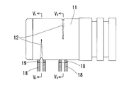
- the side view which shows an example of the flow volume adjustment member used for the fuel valve which concerns on this invention 4A is a cross-sectional view taken along V a -V a
- FIG. 4B is a cross-sectional view taken along V b -V b .
- the other example of the flow volume adjustment member used for the fuel valve which concerns on this invention is shown, (a) expand
- Cross-sectional view, (b) is a cross-sectional view in the lateral width direction of the recess (V-groove) at positions L to P shown in (a).
- the side view which shows the other example of the flow volume adjustment member used for the fuel valve which concerns on this invention
- the perspective view which shows the other example of the flow volume adjustment member used for the fuel valve which concerns on this invention.
- FIG. 1 shows a fuel tank using the fuel valve according to the present invention
- FIGS. 2A and 2B show the fuel valve.
- This fuel valve is used when the tank 1 is filled with liquid fuel L such as gasoline or kerosene and the liquid fuel L is sent to a combustion device (not shown), and is used in a state where it is laid sideways.
- liquid fuel L such as gasoline or kerosene
- a cap 2 is fitted in the mouth of the tank 1.
- the cap 2 has a fuel mixing chamber 3, a liquid fuel passage 4, an air passage 5, and a fuel outlet 6, and an air pump 7 that sends air into the tank 1 to pressurize it,
- a stand 8 is provided to support the tank 1 in a sideways state.
- a liquid fuel transport pipe 9 and an air transport pipe 10 are provided in the tank 1, and one end side (suction port side) of the liquid fuel transport pipe 9 is in one end side (suction port) of the air transport pipe 10 in the liquid fuel L. Side) is located in the air A, respectively. Further, the other end side (discharge port side) of the liquid fuel transport pipe 9 is connected to the liquid fuel flow path 4, and the other end side (discharge port side) of the air transport pipe 10 is connected to the air flow path 5.
- the fuel mixing chamber 3 is provided with a cylindrical flow rate adjusting member 11.
- a predetermined amount of gap g for fuel flow is secured between the inner surface of the fuel mixing chamber 3 and the cylindrical surface of the flow rate adjusting member 11.
- Two V-grooves 12 are formed on the cylindrical surface of the flow rate adjusting member 11 along the circumferential direction.
- a flow rate adjusting knob 13 is inserted into the flow rate adjusting member 11 coaxially therewith.
- the flow rate adjustment knob 13 slides within a predetermined range in the axial direction with respect to the flow rate adjustment member 11, and is integrated with the flow rate adjustment member 11 around the axis by engagement of key portions (not shown). It is designed to rotate. By adjusting the rotation angle of the rotation, the flow rates of the liquid fuel L and the air A are adjusted.
- the flow rate adjusting knob 13 also serves as a valve shaft of a safety valve, and a distal end side thereof is a valve body 14.
- the valve body 14 closes the fuel outlet 6 and the flow control knob 13 may be rotated carelessly when carrying the fuel tank.
- the liquid fuel L or the like does not flow (see FIG. 2A).
- the flow rate adjusting knob 13 is slid in the reverse direction to open the valve body 14, the liquid fuel L or the like can be flowed in accordance with the rotation angle (in FIG. 2B). See arrow f).
- the steel ball 16 urged by the lock spring 15 is fitted into the lock groove 17 formed in the flow rate adjusting knob 13, and this valve opening / closing is performed. The state is stably maintained.
- the flow rate adjusting knob 13 may also serve as the valve shaft of the safety valve, or the valve shaft of the safety valve may be configured as a separate member from the flow rate adjusting knob 13. Also good.
- the flow rate adjustment of the liquid fuel L and the air A by the flow rate adjustment member 11 will be described with reference to FIGS.
- the O-ring 19 of the discharge part 18 provided in each of the liquid fuel flow path 4 and the air flow path 5 is abutted against the cylindrical surface of the flow rate adjusting member 11 (see FIG. 3. Is omitted.).
- the O-ring 19 (discharge portion 18) is urged toward the cylindrical surface by a discharge spring 20 provided in both the flow paths 4 and 5 (see FIGS. 2A and 2B).
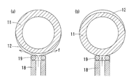
- the flow rate adjusting member 11 rotates around its axis as described above. This rotation, by changing the relative position of the V groove 12 and the O-ring 19, (see a portion indicated by V a in FIG. 4) when the O-ring 19 is positioned to extend across the V-groove 12, the flow path 4 and 5, a flow path is formed between the discharge ports of the transport pipes 9 and 10 and the V groove 12, and the liquid fuel L and the like flow (see FIG. 5A).
- the O-ring 19 is located at a location where the V-groove 12 is not formed (see the location indicated by Vb in FIG. 4), the flow path is not formed, and the liquid fuel L or the like Does not flow (see FIG. 5B).
- the flow rate adjusting member 11 is formed with two V-grooves 12 and 12 for individually adjusting the flow rate of the liquid fuel L and the flow rate of the air A.
- the liquid fuel L and air A that have passed through the two V grooves 12, 12 flow into the gap g between the inner wall of the fuel mixing chamber 3 and the cylindrical surface of the flow rate adjusting member 11, and are mixed. And sent to a combustion appliance (not shown) (see arrow f in FIG. 2 (b)).
- the groove shape (depth and width) and relative position of the two V grooves 12 and 12 are appropriately determined based on the usage mode of the combustion appliance.
- a combustion appliance using liquid fuel L such as gasoline or kerosene generally performs preheating treatment as described above and normally heats the vaporizer before combustion.
- the fuel valve according to the present invention heats the carburetor by preheating before normal combustion, and discharges the liquid fuel L remaining in the fuel flow path after use to lower the tank internal pressure to atmospheric pressure. For this reason, the flow rates of the liquid fuel L and the air A are individually adjusted.
- 6A and 6B show the formation pattern of the V groove 12 for adjusting the flow rate.
- the V-groove 12 for the liquid fuel L is formed within the adjustment range from “ignition” to “low heat”, and the depth of the V-groove 12 becomes shallower and narrower toward the “low heat” side. .
- the V-groove 12 for the air A is formed at each position of “ignition” and “exhaust”, and the depth of the V-groove 12 is deeper and the width at the “exhaust” position than “ignition”. It is getting bigger.
- the V-groove 12 for the air A can be formed to increase the injection pressure so that the air A can be taken together with the liquid fuel L from the fuel tank at the “low fire” adjustment position.
- the order of the ignition operation, the high-low to low-fire operation, and the exhaust operation in the flow rate adjusting member 11 is not limited to the order shown in FIG. 6.
- the “fire-extinguishing operation” is performed between the low-fire operation and the exhaust operation.
- the position can be appropriately changed as necessary.
- the V-groove 12 is not only provided for one discharge unit 18 but also as an aggregate of a plurality of V-grooves 12 as shown in FIG. You may comprise.
- By finely adjusting the flow rate of fuel and the like by shifting the start and end positions of each V-groove 12 constituting this assembly, or by appropriately changing the depth and width of each V-groove 12 for each circumferential position. It can be carried out.
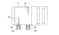
- the V groove 12 may be along the axial direction of the cylindrical flow rate adjusting member 11 as shown in FIG. In this case, by relatively sliding the O-ring 19 and the V-groove 12 in this axial direction, the fuel flow rate can be adjusted similarly to the flow rate adjusting member 11 shown in FIG.
- this groove shape is not limited to this V-groove, and other groove shapes such as a rectangular cross section, or a hollow shape. It can also be.
- This groove shape (depth, width, etc.) can be appropriately changed in consideration of a desired flow rate. For example, if a very small amount of fuel is to be supplied, a narrow and shallow groove may be formed. If fine adjustment of the flow rate is desired, the flow rate adjustment member 11 and the discharge unit 18 (O-ring 19) The amount of change in the groove depth and width in the relative sliding direction may be moderated. Further, when the concave portion 12 is formed into a groove shape in this way, even if foreign matter adheres in the groove, the foreign matter is quickly removed as the O-ring 19 slides. For this reason, the malfunction resulting from clogging of a flow path (recessed part 12) can also be prevented.
- the above-described minute supply of fuel and the like, fine adjustment of the flow rate, and prevention of clogging of the flow path are the weak points of the needle valve that adjusts the valve opening between the orifice and the needle by rotating the screw.
- the merit of employing the adjusting mechanism according to the present application is great. And since it is the simple structure which only abuts the discharge port side of the transport pipes 9 and 10 to the flow volume adjustment member 11, while having durability, its maintainability is also high.
- a plurality of V-grooves are formed and the flow rates of the liquid fuel L and the air A are individually adjusted.
- a configuration in which only the flow rate of L is adjusted, or a configuration in which the flow rate of three or more types of liquid fuel L, vaporized fuel, or air A is individually adjusted may be employed.
- the flow rate adjusting member 11 not only a cylindrical shape but also, for example, a conical shape or a flat shape can be appropriately employed.
Landscapes
- Engineering & Computer Science (AREA)
- General Engineering & Computer Science (AREA)
- Mechanical Engineering (AREA)
- Chemical & Material Sciences (AREA)
- Combustion & Propulsion (AREA)
- Feeding And Controlling Fuel (AREA)
- Multiple-Way Valves (AREA)
- Taps Or Cocks (AREA)
Abstract
Description
2 キャップ
3 燃料混合室
4 液体燃料流路
5 空気流路
6 燃料取り出し口
7 空気ポンプ
8 スタンド
9 液体燃料輸送管
10 空気輸送管
11 流量調節部材
12 V溝(凹部)
13 流量調節つまみ
14 弁体
15 ロックばね
16 鋼球
17 ロック溝
18 吐出部
19 Oリング
20 吐出ばね
L 液体燃料
A 空気
Claims (6)
- 表面に凹部(12)を形成した流量調節部材(11)と、一端側が燃料を充填したタンク(1)内に設けられ、他端側が前記表面に突き当てられた輸送管とを備え、
前記他端側と前記凹部(12)の相対位置を変化させて、前記凹部(12)が、突き当てられた前記輸送管の管内外に跨るように位置した際に、前記輸送管と前記凹部(12)との間の隙間を通って、前記燃料が流れ得るようにした燃料バルブ。 - 液体燃料(L)と、空気(A)とが共存するタンク(1)内に、前記液体燃料(L)と前記空気(A)をそれぞれ流す輸送管(9、10)の一端側を設け、両輸送管(9、10)を流れる前記液体燃料(L)及び空気(A)の流量調節を個別になし得るようにした燃料バルブ。
- 表面に凹部(12)を形成した流量調節部材(11)を備え、前記輸送管(9、10)の他端側が前記表面に突き当てられており、前記他端側と前記凹部(12)の相対位置を変化させて、前記凹部(12)が、突き当てられた前記輸送管(9、10)の管内外に跨るように位置した際に、前記輸送管と前記凹部(12)との間の隙間を通って、前記液体燃料(L)及び空気(A)が流れ得るようにした請求項2に記載の燃料バルブ。
- 前記流量調節部材(11)が円筒形状をしており、その円筒面に前記凹部(12)が形成されている請求項1又は3に記載の燃料バルブ。
- 前記凹部(12)が、前記相対位置の変位方向に沿う溝状であって、この溝の深さ又は幅の少なくとも一方を前記変位方向位置によって変化させ、前記変位方向の溝の断面積の大きさを変えることによって、この溝内を流れる燃料の流量を調節するようにした請求項1、3又は4のいずれか一つに記載の燃料バルブ。
- 前記流量調節部材(11)が円筒形状であって、その円筒軸周りに回転自在となっており、その円筒面に、前記回転方向に沿う前記液体燃料(L)及び前記空気(A)の流量を調節する溝状の凹部(12)がそれぞれ形成され、
前記流量調節部材(11)の回転角度に対応して、点火位置、火力調節位置、及び排気位置がそれぞれ決められ、前記点火位置では、前記液体燃料(L)用及び空気(A)用の凹部(12)がそれぞれ形成され、前記火力調節位置では、強火位置側で断面積が大きく、弱火位置側で断面積が小さくなる前記液体燃料(L)用の凹部(12)が形成され、前記排気位置では、前記空気(A)用の凹部(12)のみが形成されている請求項3に記載の燃料バルブ。
Priority Applications (3)
| Application Number | Priority Date | Filing Date | Title |
|---|---|---|---|
| KR1020137017045A KR101977423B1 (ko) | 2010-12-01 | 2011-09-01 | 연료 밸브 |
| EP11844342.3A EP2653759B1 (en) | 2010-12-01 | 2011-09-01 | Fuel valve |
| US13/990,436 US9568151B2 (en) | 2010-12-01 | 2011-09-01 | Fuel valve |
Applications Claiming Priority (2)
| Application Number | Priority Date | Filing Date | Title |
|---|---|---|---|
| JP2010268575A JP5702998B2 (ja) | 2010-12-01 | 2010-12-01 | 燃料バルブ |
| JP2010-268575 | 2010-12-01 |
Publications (1)
| Publication Number | Publication Date |
|---|---|
| WO2012073569A1 true WO2012073569A1 (ja) | 2012-06-07 |
Family
ID=46171525
Family Applications (1)
| Application Number | Title | Priority Date | Filing Date |
|---|---|---|---|
| PCT/JP2011/069920 Ceased WO2012073569A1 (ja) | 2010-12-01 | 2011-09-01 | 燃料バルブ |
Country Status (5)
| Country | Link |
|---|---|
| US (1) | US9568151B2 (ja) |
| EP (1) | EP2653759B1 (ja) |
| JP (1) | JP5702998B2 (ja) |
| KR (1) | KR101977423B1 (ja) |
| WO (1) | WO2012073569A1 (ja) |
Families Citing this family (1)
| Publication number | Priority date | Publication date | Assignee | Title |
|---|---|---|---|---|
| WO2023274394A1 (zh) * | 2021-07-02 | 2023-01-05 | 浙江三花汽车零部件有限公司 | 一种电动阀 |
Citations (5)
| Publication number | Priority date | Publication date | Assignee | Title |
|---|---|---|---|---|
| US4575043A (en) | 1983-10-06 | 1986-03-11 | The Boc Group, Inc. | Needle valve |
| JPS6186512A (ja) * | 1984-10-04 | 1986-05-02 | Matsushita Electric Ind Co Ltd | タンク装置 |
| JPH0251670A (ja) * | 1988-08-10 | 1990-02-21 | Kitazawa Valve:Kk | 立型三方ボールバルブ |
| JPH06235466A (ja) | 1993-02-08 | 1994-08-23 | Motoyama Seisakusho:Kk | ダイヤフラム型流量調節弁 |
| JP2010236686A (ja) | 2009-03-31 | 2010-10-21 | Keihin Corp | 流路開閉弁 |
Family Cites Families (23)
| Publication number | Priority date | Publication date | Assignee | Title |
|---|---|---|---|---|
| US1502483A (en) * | 1922-10-23 | 1924-07-22 | Leo F O'flaherty | Mixing valve |
| US1662978A (en) * | 1925-03-05 | 1928-03-20 | Charles R Robinson | Regulating-valve mechanism for gasoline lanterns |
| US2145383A (en) * | 1930-03-19 | 1939-01-31 | Ex Cell O Corp | Fluid distributor |
| US2018853A (en) * | 1932-03-10 | 1935-10-29 | Frederick J Hitchcock | Oil burner apparatus and the like |
| US2129100A (en) * | 1934-12-28 | 1938-09-06 | Florence Wehrle Stove Co | Fluid control means |
| US2139819A (en) * | 1935-08-02 | 1938-12-13 | Graetz Fritz | Preheater |
| US2291563A (en) * | 1941-05-12 | 1942-07-28 | Lincoln Eng Co | Valve |
| US2406524A (en) * | 1943-03-18 | 1946-08-27 | Electrol Inc | Control unit and dump valve |
| GB695424A (en) * | 1950-08-17 | 1953-08-12 | Aladdin Ind Inc | Valve control mechanism for hydrocarbon fuel burning devices |
| US2630325A (en) * | 1950-12-26 | 1953-03-03 | Earl C Reynolds | Water softener control means |
| US2833311A (en) * | 1954-06-28 | 1958-05-06 | Baldelli Gaetano | Metering device for liquids or solutions |
| US2940674A (en) * | 1954-09-23 | 1960-06-14 | Robert H Hunter | Instant flame torch |
| FR1252757A (fr) * | 1959-12-22 | 1961-02-03 | Citroen Sa Andre | Valve à trois voies à longueur de recouvrement réglable |
| US3049149A (en) * | 1959-12-22 | 1962-08-14 | Citroen Sa Andre | Three-way slide valve with adjustable overlap |
| US3231234A (en) * | 1963-02-11 | 1966-01-25 | Dro Engineering Company Di | Metering valve |
| US3285278A (en) * | 1964-01-20 | 1966-11-15 | Standard Screw | R cartridge seal design and arrangement |
| US3814129A (en) * | 1972-09-25 | 1974-06-04 | Squibb & Sons Inc | Sampling valve |
| US3882883A (en) * | 1973-11-19 | 1975-05-13 | Fairmont Railway Motors Inc | Closed-open center hydraulic valve assembly |
| US4230446A (en) * | 1978-06-05 | 1980-10-28 | Acroform Corporation | Camp lantern |
| JPS6433410A (en) * | 1987-07-29 | 1989-02-03 | Nippon Tansan Gas Co Ltd | Portable torch |
| US4915133A (en) * | 1989-03-15 | 1990-04-10 | Harrison C L Scott | Valve device for piping systems |
| DE10152186C1 (de) * | 2001-10-23 | 2003-06-12 | Ballard Power Systems | Brennstoffzellanlage mit einer Vorrichtung zur dosierten Zufuhr von sauerstoffhaltigem Medium an Dosierstellen eines Gaserzeugungssystems |
| US8942150B2 (en) * | 2007-03-19 | 2015-01-27 | Qualcomm Incorporated | Uplink timing control |
-
2010
- 2010-12-01 JP JP2010268575A patent/JP5702998B2/ja active Active
-
2011
- 2011-09-01 WO PCT/JP2011/069920 patent/WO2012073569A1/ja not_active Ceased
- 2011-09-01 US US13/990,436 patent/US9568151B2/en active Active
- 2011-09-01 EP EP11844342.3A patent/EP2653759B1/en active Active
- 2011-09-01 KR KR1020137017045A patent/KR101977423B1/ko active Active
Patent Citations (5)
| Publication number | Priority date | Publication date | Assignee | Title |
|---|---|---|---|---|
| US4575043A (en) | 1983-10-06 | 1986-03-11 | The Boc Group, Inc. | Needle valve |
| JPS6186512A (ja) * | 1984-10-04 | 1986-05-02 | Matsushita Electric Ind Co Ltd | タンク装置 |
| JPH0251670A (ja) * | 1988-08-10 | 1990-02-21 | Kitazawa Valve:Kk | 立型三方ボールバルブ |
| JPH06235466A (ja) | 1993-02-08 | 1994-08-23 | Motoyama Seisakusho:Kk | ダイヤフラム型流量調節弁 |
| JP2010236686A (ja) | 2009-03-31 | 2010-10-21 | Keihin Corp | 流路開閉弁 |
Also Published As
| Publication number | Publication date |
|---|---|
| US9568151B2 (en) | 2017-02-14 |
| KR101977423B1 (ko) | 2019-05-10 |
| EP2653759A1 (en) | 2013-10-23 |
| EP2653759B1 (en) | 2020-07-29 |
| JP5702998B2 (ja) | 2015-04-15 |
| US20130319881A1 (en) | 2013-12-05 |
| EP2653759A4 (en) | 2018-01-24 |
| KR20130121906A (ko) | 2013-11-06 |
| JP2012117764A (ja) | 2012-06-21 |
Similar Documents
| Publication | Publication Date | Title |
|---|---|---|
| KR100802455B1 (ko) | 가스버너의 공기혼합장치 | |
| US20150056563A1 (en) | Dual venturi for combustor | |
| AU2007281757A1 (en) | Backpacking stove | |
| US6182651B1 (en) | Open air stove | |
| JP5702998B2 (ja) | 燃料バルブ | |
| USRE29457E (en) | Fuel control means for burners | |
| US4522582A (en) | Fuel control system for burners | |
| JP6032716B2 (ja) | 燃料調節部を備えたバーナー | |
| US3485567A (en) | Liquid fuel burning appliance and components therefor | |
| JP5113570B2 (ja) | 輝炎バーナ | |
| JP2010054087A (ja) | ガスタービン燃焼器およびガスタービン燃焼器の運転方法 | |
| US2809663A (en) | Blowpipe assembly | |
| JP5768982B2 (ja) | ガスコック装置 | |
| JP5078030B2 (ja) | 多種燃料の同軸燃焼バーナ装置の運転方法 | |
| US20130036839A1 (en) | Flame atmosphere analyser | |
| KR101473915B1 (ko) | 연소효율 향상을 위한 공기와 연료의 혼합장치 | |
| US727588A (en) | Gas-burner. | |
| KR101473914B1 (ko) | 연소효율 향상을 위한 공기와 연료의 혼합장치 | |
| US5655512A (en) | Fuel valve for a campstove | |
| KR20170026031A (ko) | 오리피스 방식의 정밀 가스기기 조절밸브 | |
| JP2023180177A (ja) | バーナー | |
| JP2025164462A (ja) | 燃焼装置及びこれに用いる燃焼・燃料制御弁 | |
| KR200347293Y1 (ko) | 가스공급량 조절기능을 갖는 가스렌지용 점화 라이타 | |
| KR101498093B1 (ko) | 연료공급 조절부를 구비한 액출버너 | |
| KR810000629Y1 (ko) | 버 어 너 |
Legal Events
| Date | Code | Title | Description |
|---|---|---|---|
| 121 | Ep: the epo has been informed by wipo that ep was designated in this application |
Ref document number: 11844342 Country of ref document: EP Kind code of ref document: A1 |
|
| NENP | Non-entry into the national phase |
Ref country code: DE |
|
| WWE | Wipo information: entry into national phase |
Ref document number: 2011844342 Country of ref document: EP |
|
| ENP | Entry into the national phase |
Ref document number: 20137017045 Country of ref document: KR Kind code of ref document: A |
|
| WWE | Wipo information: entry into national phase |
Ref document number: 13990436 Country of ref document: US |