WO2012076615A2 - Procédé de contrôle automatique d'une cellule de mesure de pression céramique d'un capteur de pression capacitif et circuit d'évaluation pour mettre en oeuvre ce procédé - Google Patents
Procédé de contrôle automatique d'une cellule de mesure de pression céramique d'un capteur de pression capacitif et circuit d'évaluation pour mettre en oeuvre ce procédé Download PDFInfo
- Publication number
- WO2012076615A2 WO2012076615A2 PCT/EP2011/072119 EP2011072119W WO2012076615A2 WO 2012076615 A2 WO2012076615 A2 WO 2012076615A2 EP 2011072119 W EP2011072119 W EP 2011072119W WO 2012076615 A2 WO2012076615 A2 WO 2012076615A2
- Authority
- WO
- WIPO (PCT)
- Prior art keywords
- pressure
- capacitor
- measuring
- value
- measuring cell
- Prior art date
- Legal status (The legal status is an assumption and is not a legal conclusion. Google has not performed a legal analysis and makes no representation as to the accuracy of the status listed.)
- Ceased
Links
Images



Classifications
-
- G—PHYSICS
- G01—MEASURING; TESTING
- G01L—MEASURING FORCE, STRESS, TORQUE, WORK, MECHANICAL POWER, MECHANICAL EFFICIENCY, OR FLUID PRESSURE
- G01L25/00—Testing or calibrating of apparatus for measuring force, torque, work, mechanical power, or mechanical efficiency
-
- G—PHYSICS
- G01—MEASURING; TESTING
- G01L—MEASURING FORCE, STRESS, TORQUE, WORK, MECHANICAL POWER, MECHANICAL EFFICIENCY, OR FLUID PRESSURE
- G01L9/00—Measuring steady of quasi-steady pressure of fluid or fluent solid material by electric or magnetic pressure-sensitive elements; Transmitting or indicating the displacement of mechanical pressure-sensitive elements, used to measure the steady or quasi-steady pressure of a fluid or fluent solid material, by electric or magnetic means
- G01L9/0026—Transmitting or indicating the displacement of flexible, deformable tubes by electric, electromechanical, magnetic or electromagnetic means
- G01L9/003—Transmitting or indicating the displacement of flexible, deformable tubes by electric, electromechanical, magnetic or electromagnetic means using variations in capacitance
-
- G—PHYSICS
- G01—MEASURING; TESTING
- G01L—MEASURING FORCE, STRESS, TORQUE, WORK, MECHANICAL POWER, MECHANICAL EFFICIENCY, OR FLUID PRESSURE
- G01L27/00—Testing or calibrating of apparatus for measuring fluid pressure
- G01L27/007—Malfunction diagnosis, i.e. diagnosing a sensor defect
-
- G—PHYSICS
- G01—MEASURING; TESTING
- G01L—MEASURING FORCE, STRESS, TORQUE, WORK, MECHANICAL POWER, MECHANICAL EFFICIENCY, OR FLUID PRESSURE
- G01L9/00—Measuring steady of quasi-steady pressure of fluid or fluent solid material by electric or magnetic pressure-sensitive elements; Transmitting or indicating the displacement of mechanical pressure-sensitive elements, used to measure the steady or quasi-steady pressure of a fluid or fluent solid material, by electric or magnetic means
- G01L9/12—Measuring steady of quasi-steady pressure of fluid or fluent solid material by electric or magnetic pressure-sensitive elements; Transmitting or indicating the displacement of mechanical pressure-sensitive elements, used to measure the steady or quasi-steady pressure of a fluid or fluent solid material, by electric or magnetic means by making use of variations in capacitance, i.e. electric circuits therefor
Definitions
- the invention relates to a method for self-monitoring of a ceramic pressure measuring cell of a capacitive pressure sensor and to an evaluation circuit for carrying out the method according to the preamble of claims 1 and 2 or claim 9.
- Capacitive pressure sensors are used in many industries for pressure measurement. They often have a ceramic pressure measuring cell, as a transducer for the process pressure, and an evaluation for signal processing.
- Capacitive pressure measuring cells consist of a ceramic base body and a membrane, wherein a glass solder ring is arranged between the base body and the membrane. The resulting cavity between the body and membrane allows the longitudinal mobility of the membrane due to a pressure influence. On the underside of the membrane and on the opposite upper side of the main body electrodes are provided, which together form a measuring capacitor. Pressure causes a deformation of the membrane, which results in a capacitance change of the measuring capacitor.
- the capacitance change is detected and converted into a pressure measurement value.
- these pressure sensors are used to monitor or control processes. They are therefore often connected to higher-level control units (PLC).
- PLC higher-level control units
- a capacitive pressure sensor is known in which the pressure measurement value is determined from the quotient of two capacitance values, a measurement capacitor and a reference capacitor.
- a pressure measuring cell is not specifically described in this specification, the circuit shown and the method described is suitable for capacitive pressure measuring cells.
- C M denotes the capacitance of the measuring capacitor
- C R the capacitance of the reference capacitor
- p the process pressure to be determined. It is also conceivable to exchange C M and C R in the quotient. However, the given example with C M in the denominator represents the most common form in favor of the self-linearization. Therefore, this embodiment is based on this embodiment, unless stated otherwise.
- the reliability of capacitive pressure sensors is becoming increasingly important.
- the problem with capacitive pressure sensors, which operate according to the quotient method is that a medium inlet - caused by membrane breakage or made possible by a venting - due to the quotient formation could not be detected, because in both the numerator and the denominator, the dielectric constant ⁇ r changes accordingly ,
- the problem is made more difficult if the ⁇ r of the incoming medium differs only slightly from ⁇ r of air. This is especially the case when the medium to be measured is oil.
- the ⁇ r of oil is typically between 2 and 4 while the ⁇ r of air is 1.
- the object of the present invention is to provide a method for monitoring the operation of a pressure measuring cell of a capacitive pressure sensor and a corresponding evaluation circuit, which do not have the disadvantages mentioned above, in particular allow a safe and reliable detection of media entry, such as through a possible venting channel or membrane breakage ,
- the method for self-monitoring of a pressure measuring cell of a capacitive pressure sensor in a first alternative is characterized in that with an additional capacitor, which is arranged outside the pressure measuring cell, a control pressure measured value is obtained and is closed by comparing the actual pressure measured value with the control pressure measured value on the functioning of the pressure measuring cell.
- the essential idea of the invention is, in the case of a capacitive pressure sensor with a ceramic pressure measuring cell with the aid of an additional capacitor C Z , whose capacity is independent of the diaphragm pressure, to determine a control pressure measured value which is compared with the actual pressure measured value.
- the condition for this is that both the capacitance of the measuring capacitor and a proportion of that of the reference capacitor due to a pressure influence is variable, while the capacity of the additional capacitor remains constant, since it is independent of the applied pressure.
- the comparison of the actual pressure measurement value with the control pressure measured value advantageously takes place via a subtraction of the two measured values.
- a quotient formation is also conceivable, however, for example, at zero pressure, the computational risk of a division by zero could arise.
- the pressure measured value and / or the control pressure measured value are obtained by means of a quotient method.
- the denominator required for the second quotient for the control measured value is advantageously the same as that of the first for the actual pressure value.
- the dielectric would have to be determined, for example via a climate sensor, in order to compensate for fluctuations in the capacitances due to changes in the dielectric conductivity or permittivity.
- the quotient method this would not be necessary because the dielectric constant changes to the same extent both in the numerator and in the denominator.
- the calibration of the capacitive pressure sensor is carried out so that the control pressure measured value and the actual pressure measurement have the same functional dependence on the process pressure, so by simply comparing both measured values, z. B. using a differential amplifier, a diagnostic value can be determined.
- the object shown can also be solved digitally by the method for self-monitoring of a pressure measuring cell of a capacitive pressure sensor according to the invention characterized in that a processing unit consisting of at least one converter unit and a microcontroller, is provided, in which the capacitance values of the measuring capacitor and the reference capacitor are detected from both capacitance values, the pressure measured value is detected and in which a further capacitance value is detected, which corresponds to an additional capacitor and from which a control pressure measured value is obtained, wherein by comparing the pressure measured value with the Control pressure reading is closed on the functioning of the pressure cell.
- a processing unit consisting of at least one converter unit and a microcontroller
- the capacitance values of measuring capacitor and reference capacitor are detected by a converter unit and forwarded to a microcontroller, where both the quotient calculation and the comparison of pressure measurement value and control pressure measurement value take place.
- the additional capacitor can be present either as a component or component whose capacitance value is also detected by the converter unit and passed on to the microcontroller, or in the form of a stored in the processing unit, in particular in the microcontroller capacitance value.
- the invention relates to an evaluation circuit for a capacitive sensor, comprising a measuring capacitor and a reference capacitor, wherein the reference capacitor is provided in a differentiating branch and the measuring capacitor in an integrating branch, which are both connected in parallel and supplied with a voltage signal. wherein the output of the integrating branch is supplied to the differentiating branch, at whose output a first pressure-dependent output signal is applied.
- a control measuring branch is connected in parallel with the differentiating branch with an additional capacitor, and the output signal of the integrating branch is additionally supplied to the control measuring branch, at whose output a second pressure-dependent output signal is present. Both output signals are then fed to a comparator unit, at whose output a diagnostic signal is output.
- the two pressure-dependent output signals of differential and control measuring branch can be supplied both directly to the comparator unit and indirectly, for example via a respective sample-and-hold circuit, which converts the square-wave voltage to DC voltage.
- FIG. 1 is a block diagram of a capacitive pressure sensor
- FIG. 2 is a schematic sectional view of a capacitive pressure measuring cell
- FIG. 3 shows an evaluation circuit for a capacitive pressure measuring cell according to FIG. 2,
- FIG. 4 shows an evaluation circuit according to the invention for a capacitive pressure measuring cell according to FIG. 2,
- FIG. 5 shows an evaluation circuit according to the invention for a capacitive pressure measuring cell according to FIG. 2 without sample-and-hold circuits
- FIG. 6 shows a diagram which simplifies the behavior of the three capacitance values C M , C R , C Z over the pressure
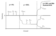
- FIG. 7 shows a diagram which simplifies the behavior of the diagnostic voltage U DIAG in the three states of no pressure, pressure influence and cell defect due to medium entry, and
- FIG. 8 shows an alternative to the figures 3-5 embodiment of the method according to the invention.
- the pressure sensor 1 shows a block diagram of a typical capacitive pressure sensor used to measure a process pressure p (eg of oil, milk, water, etc.).
- the pressure sensor 1 consists essentially of a pressure measuring cell 10 and an evaluation 20.
- the evaluation 20 has an analog evaluation circuit 30 and a microcontroller ⁇ C, in which the analog output signal of the evaluation circuit 20 is digitized and further processed.
- the microcontroller ⁇ C provides the evaluation result as a digital or analog output signal z.
- the pressure sensor 1 is connected to a power supply line (12 - 36 V).
- FIG. 2 shows a typical capacitive pressure measuring cell 10, as it is widely used in capacitive pressure sensors, in a schematic representation.
- the pressure measuring cell 10 essentially consists of a base body 12 and a membrane 14, which are connected to each other via a glass solder ring 16.
- the main body 12 and the diaphragm 14 delimit a cavity 19, which is connected to the rear side of the pressure measuring cell 10 via a venting channel 18, preferably only at low pressure ranges of up to 50 bar.
- a plurality of electrodes are provided which form a reference capacitor C R and a measuring capacitor C M.
- the measuring capacitor C M is formed by the membrane electrode ME and the center electrode M, the reference capacitor C R through the ring electrode R and the membrane electrode ME.
- the process pressure p acts on the membrane 14, which bends more or less in accordance with the pressurization, wherein substantially the distance of the membrane electrode ME to the center electrode M changes. This leads to a corresponding change in capacitance of the measuring capacitor C M.
- the influence on the reference capacitor C R is lower, since the distance between the ring electrode R and the membrane electrode ME changes less than the distance between the membrane electrode ME to the center electrode M.
- C M therefore designates both the measuring capacitor itself, as well as its capacity.
- FIG. 3 shows a known evaluation circuit 30 for the pressure measuring cell 10 in more detail.
- the measuring capacitor C M is arranged together with a resistor R 1 in an integrating branch IZ and the reference capacitor C R together with a resistor R 2 in a differentiating branch DZ.
- a square wave voltage U E0 At the input of Integrierzweigs IZ is a square wave voltage U E0 , which preferably varies symmetrically by 0 volts.
- the input voltage U E0 is converted via the resistor R 1 and the measuring capacitor C M by means of an operational amplifier OP1, which acts as an integrator, into a linearly rising or falling voltage signal (depending on the polarity of the input voltage) output at the output COM of the integrating branch IZ becomes.
- the measuring point P1 is virtually grounded by the operational amplifier OP1.
- the output COM is connected to a threshold comparator SG, which drives a square-wave generator RG. As soon as the voltage signal at the output COM exceeds or falls below a threshold value, the comparator SG changes its output signal, whereupon the square-wave generator inverts its output voltage in each case.
- the differentiating branch DZ is further comprised of an operational amplifier OP2, a voltage divider with the two resistors R 5 and R 6, and a feedback resistor R. 7
- the output of the operational amplifier OP2 is connected to a sample-and-hold circuit S & H.
- the measurement voltage U Mess At the output of the sample-and-hold circuit S & H is the measurement voltage U Mess , which is proportional to the process pressure p, which acts on the pressure measuring cell 10 is.
- the operational amplifier OP1 ensures that the connection point P1 between the resistor R 1 and the measuring capacitor C M is virtually kept at ground. As a result, a constant current I 1 flows through the resistor R 1 , which charges the measuring capacitor C M until the square-wave voltage U E0 changes its sign
- the positive and negative pulse height A + or A- of the rectangular pulse is determined via a sample and hold circuit S & H and the amount A is output as measurement voltage U Mess at the output of the operational amplifier OP3 and forwarded to the microcontroller mC (not shown). It could also be output directly as an analog value.
- the pulse height of the input voltage U E0 which is applied to the output of the square wave generator RG, is adjusted as a function of the measuring voltage U Mess in order to achieve a better linearity.
- a voltage divider consisting of the resistors R 20 and R 10 is provided. This voltage divider is connected to a reference voltage VREF and advantageously adjustable.
- the evaluation circuit 30a according to the invention is shown. However, this circuit corresponds to the circuit of FIG. 3, however, with an additional control measuring branch KMZ and a comparator unit VE.
- the control measuring branch KMZ comprises a resistor R 2 'and an additional capacitor C Z , which are arranged parallel to the resistor R 1 and the measuring capacitor C M.
- an operational amplifier OP2' To the measuring point P2 'is connected an operational amplifier OP2', which operates as a differentiator as the operational amplifier OP2.
- U D At the output of the operational amplifier OP2 'is a square wave voltage U D , which is proportional to the expression C Z / C M - 1.
- This square-wave voltage is also rectified with a sample and hold circuit S & H '(voltage U A' at point A ') and then compared with the measuring voltage U Mess in a comparator unit VE with the aid of a differential amplifier OP4.
- the functional profile of the square-wave voltage U D - or the voltage U A ' at A' - can be dimensioned in dependence on the process pressure p in accordance with the course of the measuring voltage U Mess .
- the diagnostic voltage U DIAG At the output of the differential amplifier OP4 is the diagnostic voltage U DIAG .
- the diagnostic voltage U DIAG essentially follows the expression
- correction factors k1 to k4 are advantageously realized by tunable resistor networks; their placements in the illustrated formula are intended to be exemplary only and, of course, may be changed depending on the intended direction of proportionality.
- a medium entry or a diaphragm rupture only has an effect on the capacitance values of the two capacitors C R and C M or only on the capacitance value of one of these two capacitors, but not on C Z , so that in this case the voltage U DIAG noticeably decreases from zero differs.
- This deviation can be registered by a microcontroller (not shown) and a corresponding reaction initiated. This can, for. B. exist in an alarm message, which is forwarded to the PLC or an on-site signaling.
- Fig. 5 shows a somewhat modified circuit 30b which operates without a sample and hold element.
- the advantage over the embodiment in Fig. 4 is that the circuit complexity is reduced and thus the manufacturing cost can be reduced.
- the rectangular diagnosis signal makes the interpration more difficult.
- the illustrated resistors are only symbolically meant in FIG. 5 and may each include a resistor network.
- the measuring voltage U R is a square-wave voltage as in the previously described embodiments. Therefore, the diagnostic signal U DIAG is output in a rectangular manner in this case.
- Both circuits 30a, 30b are suitable for both analog and digital further processing with a microcontroller.
- the pressure measuring cell 10 of the capacitive pressure sensor 1 has a measuring capacitor C M and a reference capacitor C R.
- As the voltage U R is advantageously obtained by a quotient method from the capacitance values of the measuring capacitor C M and the reference capacitor C R.
- an additional capacitor C Z also via a quotient method, a control pressure measured value p ', z. B. the voltage U D won. Since the additional capacitor C Z is arranged so that it remains completely unaffected by a membrane rupture of the membrane 14 or by a medium inlet into the pressure measuring cell 10, the two measured values change in each case differently.
- the calibration of the capacitive pressure sensor takes place so that the control pressure measured value p 'and the pressure measured value p have the same functional dependence on the process pressure. It goes without saying that parts of the evaluation circuit 30a can also be implemented digitally in a microcontroller. The invention makes it possible to expand an existing capacitive pressure sensor by a diagnostic function without much effort.
- the method according to the invention and the corresponding evaluation circuit are suitable not only for determining a medium entry in a membrane breakage but also for the diagnosis of cracking in the membrane 14, because in this case the flexural rigidity of the membrane 14 changes and this determined differently on the above the reference capacitor C R. Measured value p 'and the pressure measured value p determined via the measuring capacitor C M.
- FIG. 6 shows in simplified form how the three capacitance values C M , C R , C Z behave above the pressure.
- the curve of the measuring capacitor C M has the largest slope, because it is located in the middle of the diaphragm 14 of the pressure measuring cell 10 and thus the diaphragm 14 has the greatest deflection under the influence of pressure here.
- the reference capacitor C R is located at the edge of the membrane 14, where the change in distance between the two electrodes R, ME is lower. Therefore, the capacity increase per unit pressure is less than the measuring capacitor C M. It can finally be seen that the capacity of the additional capacitor C Z does not change and remains constant over the entire pressure curve. That is the essential condition of the invention.
- the arrow between C M and C R illustrates the magnitude of the actual measurement voltage U R , the arrow between C M and C Z the magnitude of the output voltage U D of the control measuring branch KMZ.
- FIG. 7 shows a diagram which shows the behavior of the diagnosis voltage U DIAG in the three states no pressure, pressure influence and cell defect due to medium entry. Simplified means that this is a schematic diagram, so that actual waveforms could be slightly different, especially in terms of amount. Also, other influences, such as resistive errors o. The like., Not considered.
- the fundamental signal course was modeled after an actual measurement.
- the signals U A and U A ' at the points A and A' are the converted by the sample-and-hold circuit to DC voltage output signals U R and U D of the differentiating branch DZ and the control measuring branch KMZ.
- the voltage U DIAG is the diagnostic voltage as the difference between the two signals U A and U A ' .
- the diagram thus clarifies the operation of the comparator unit VE.
- the last third of the diagram shows the signal curves at medium entry, again assuming a 50% pressure load. Since now the medium to be measured is located within the measuring cell, ie in the hollow body 19 delimited by the main body 12 and the membrane 14, the same pressure prevails as outside the membrane 14 and the now increased permittivity does not affect the amount of the quotient out. Consequently, the signal U A moves as a measure of the actual measurement voltage U measurement in the direction of 0 volts. A step-shaped waveform yields sch again through the sample-and-hold circuit S & H.
- the signal U A ' moves due to the still constant capacitance C Z , which is in the numerator of the quotient for calculating U A' , and due to increased permittivity unilaterally increasing capacity C M , in the denominator of the quotient for the calculation of U A ' stands, in a negative direction.
- the diagnostic voltage U DIAG as a difference between the two signals U A and U A ' now moves clearly in the positive direction. At least - and that is the decisive factor - the diagnostic voltage U DIAG is not equal to zero, which can be recognized as a measure of a cell defect and further processed.
- FIG. 8 shows an alternative embodiment of the method according to the invention to FIGS. 4 and 5.
- the pressure measuring cell 10 is identical to the previously described embodiments.
- the capacitance changes of C M and C R resulting from the pressure influence are not evaluated analogously but digitally in a processing unit 50 consisting of at least one converter unit 55 and a microcontroller 51.
- a processing unit 50 consisting of at least one converter unit 55 and a microcontroller 51.
- a converter unit 55 is provided which, for example, can be designed as an AD7745 circuit "Capacitance To Digital Converter” by Analog Devices.
- a converter unit 55 is provided for both capacitors C M and C R.
- C M and C R are then fed to a microcontroller 51, in whose processor unit 52 the quotient terms C R / C M -1 and C Z / C M -1 are calculated and compared in the previously described manner by subtraction ,
- the value for C Z either comes, as shown in FIG. 8, from a memory unit 53, which is preferably located within the microcontroller 51 and in which a capacitance value representing an additional capacitor C Z is stored, or alternatively from outside the processing unit 50 arranged, designed as a component or component capacitor whose capacitance is also detected by a converter unit 55 and digitized the microcontroller 51 is supplied.
Landscapes
- Physics & Mathematics (AREA)
- General Physics & Mathematics (AREA)
- Electromagnetism (AREA)
- Health & Medical Sciences (AREA)
- Chemical & Material Sciences (AREA)
- Engineering & Computer Science (AREA)
- Analytical Chemistry (AREA)
- Biomedical Technology (AREA)
- Measuring Fluid Pressure (AREA)
Abstract
L'invention concerne un capteur de pression capacitif pourvu d'une cellule de mesure de pression céramique. Selon l'invention, une valeur de mesure de pression de contrôle est déterminée, de préférence par la méthode des quotients, au moyen d'un condensateur auxiliaire dont la capacité est indépendante de la pression de la membrane, puis cette valeur de mesure de pression de contrôle est comparée avec la valeur de mesure de pression réelle. De façon avantageuse, l'étalonnage du capteur de pression capacitif est réalisé de sorte que la valeur de mesure de pression de contrôle et la valeur de mesure de pression réelle présentent la même dépendance fonctionnelle vis-à-vis de la pression de processus p, de sorte qu'une valeur de diagnostic puisse être déterminée par simple comparaison des deux valeurs de mesure, p. ex. au moyen d'un amplificateur différenciateur.
Priority Applications (2)
| Application Number | Priority Date | Filing Date | Title |
|---|---|---|---|
| EP11794711.9A EP2606330B1 (fr) | 2010-12-08 | 2011-12-07 | Procédé de contrôle automatique d'une cellule de mesure de pression céramique d'un capteur de pression capacitif et circuit d'évaluation pour mettre en oeuvre ce procédé |
| US13/883,851 US9316557B2 (en) | 2010-12-08 | 2011-12-07 | Method for self-monitoring a ceramic pressure measuring cell of a capacitive pressure sensor and evaluation circuit for carrying out said method |
Applications Claiming Priority (2)
| Application Number | Priority Date | Filing Date | Title |
|---|---|---|---|
| DE102010062622A DE102010062622A1 (de) | 2010-12-08 | 2010-12-08 | Verfahren zur Selbstüberwachung einer keramischen Druckmesszelle eines kapazitiven Drucksensors und eine Auswerteschaltung zur Durchführung des Verfahrens |
| DE102010062622.8 | 2010-12-08 |
Publications (2)
| Publication Number | Publication Date |
|---|---|
| WO2012076615A2 true WO2012076615A2 (fr) | 2012-06-14 |
| WO2012076615A3 WO2012076615A3 (fr) | 2012-08-02 |
Family
ID=45346460
Family Applications (1)
| Application Number | Title | Priority Date | Filing Date |
|---|---|---|---|
| PCT/EP2011/072119 Ceased WO2012076615A2 (fr) | 2010-12-08 | 2011-12-07 | Procédé de contrôle automatique d'une cellule de mesure de pression céramique d'un capteur de pression capacitif et circuit d'évaluation pour mettre en oeuvre ce procédé |
Country Status (4)
| Country | Link |
|---|---|
| US (1) | US9316557B2 (fr) |
| EP (1) | EP2606330B1 (fr) |
| DE (1) | DE102010062622A1 (fr) |
| WO (1) | WO2012076615A2 (fr) |
Families Citing this family (14)
| Publication number | Priority date | Publication date | Assignee | Title |
|---|---|---|---|---|
| DE102014201529A1 (de) | 2014-01-28 | 2015-07-30 | Siemens Aktiengesellschaft | Verfahren zum Betreiben eines Druckmessumformers sowie Druckmessumformer |
| US9869599B2 (en) * | 2014-09-30 | 2018-01-16 | Rosemount Inc. | High-temperature pressure sensing |
| DE102014118616A1 (de) * | 2014-12-15 | 2016-06-16 | Endress + Hauser Gmbh + Co. Kg | Druckmessaufnehmer |
| US9897504B2 (en) * | 2015-04-20 | 2018-02-20 | Infineon Technologies Ag | System and method for a MEMS sensor |
| EP3244272A1 (fr) * | 2016-05-09 | 2017-11-15 | Siemens Aktiengesellschaft | Procede de surveillance d'une courbe de protection de pression de condensateur avec une fonction polygone |
| US9983032B1 (en) * | 2017-06-01 | 2018-05-29 | Nxp Usa, Inc. | Sensor device and method for continuous fault monitoring of sensor device |
| DE102018118645B3 (de) * | 2018-08-01 | 2019-11-07 | Ifm Electronic Gmbh | Verfahren zur Funktionsüberwachung einer Druckmesszelle eines kapazitiven Drucksensors |
| DE102018121463A1 (de) * | 2018-09-03 | 2020-03-05 | Ifm Electronic Gmbh | Kapazitiver Drucksensor mit einer Druckmesszelle und einer Auswerteeinheit, die räumlich getrennt voneinander angeordnet sind |
| DE102020100675B4 (de) * | 2019-01-14 | 2025-09-04 | Ifm Electronic Gmbh | Kapazitiver Drucksensor mit Temperaturerfassung |
| DE102019124083B3 (de) | 2019-09-09 | 2020-10-22 | Ifm Electronic Gmbh | Absolutdruckmessgerät mit einer relativ messenden Druckmesszelle |
| DE102019129264B4 (de) | 2019-10-30 | 2021-07-15 | Ifm Electronic Gmbh | Verfahren zur Funktionsüberwachung einer kapazitiven Druckmesszelle |
| DE102020122128B3 (de) * | 2020-08-25 | 2021-11-04 | Ifm Electronic Gmbh | Verfahren zur Funktionsüberwachung einer kapazitiven Druckmesszelle |
| DE102022105693B3 (de) * | 2022-03-10 | 2023-03-16 | Ifm Electronic Gmbh | Verfahren zum Betreiben einer Druckmesszelle eines kapazitiven Drucksensors |
| CN120651392A (zh) * | 2024-03-14 | 2025-09-16 | 无锡华润上华科技有限公司 | 电容式压力传感器及其制备方法 |
Citations (2)
| Publication number | Priority date | Publication date | Assignee | Title |
|---|---|---|---|---|
| EP0569573B1 (fr) | 1991-11-28 | 1996-04-10 | Endress + Hauser Gmbh + Co. | Dispositif manometrique a haute linearite |
| DE19851506C1 (de) | 1998-11-09 | 2000-10-19 | Ifm Electronic Gmbh | Auswerteverfahren für kapazitive Sensoren |
Family Cites Families (13)
| Publication number | Priority date | Publication date | Assignee | Title |
|---|---|---|---|---|
| DE3932443C1 (fr) * | 1989-09-28 | 1990-12-20 | Endress U. Hauser Gmbh U. Co, 7864 Maulburg, De | |
| US5613398A (en) * | 1994-01-24 | 1997-03-25 | Chrysler Corporation | Smart fuel tank module |
| US5663506A (en) * | 1995-08-21 | 1997-09-02 | Moore Products Co. | Capacitive temperature and pressure transducer |
| DE19648048C2 (de) * | 1995-11-21 | 2001-11-29 | Fuji Electric Co Ltd | Detektorvorrichtung zur Druckmessung basierend auf gemessenen Kapazitätswerten |
| DE19633630A1 (de) * | 1996-08-21 | 1998-02-26 | Endress Hauser Gmbh Co | Auswerteeinheit eines Differenzdrucksensors |
| WO2001014842A1 (fr) * | 1999-08-20 | 2001-03-01 | Hitachi, Ltd. | Detecteur de pression semi-conducteur et dispositif de detection de pression |
| EP1677084A1 (fr) * | 2004-12-22 | 2006-07-05 | Roxer Industries S.A. | Capteur de niveau d'un liquide et méthode d'estimation. |
| JP2008008688A (ja) * | 2006-06-27 | 2008-01-17 | Yamatake Corp | 容量式圧力センサ |
| US20080301211A1 (en) | 2007-06-01 | 2008-12-04 | United States of America as represented by the Administrator of the National Aeronautics and | Systems, methods and apparatus for d-dimensional formulation and implementation of recursive hierarchical segmentation |
| EP2189774B1 (fr) * | 2008-11-20 | 2014-12-31 | VEGA Grieshaber KG | Procédé destiné à la détection et à la compensation d'un changement de température rapide sur une cellule de mesure de pression |
| US8281655B2 (en) * | 2009-04-03 | 2012-10-09 | Eaton Corporation | Fuel gauging system utilizing a digital fuel gauging probe |
| DE102009002662B4 (de) * | 2009-04-27 | 2022-11-24 | Ifm Electronic Gmbh | Kapazitiver Drucksensor als Kombinationssensor zur Erfassung weiterer Messgrößen |
| DE102010001797B4 (de) * | 2010-02-11 | 2023-09-28 | Robert Bosch Gmbh | Mikromechanisches Sensorelement zur kapazitiven Differenzdruckerfassung |
-
2010
- 2010-12-08 DE DE102010062622A patent/DE102010062622A1/de not_active Withdrawn
-
2011
- 2011-12-07 WO PCT/EP2011/072119 patent/WO2012076615A2/fr not_active Ceased
- 2011-12-07 US US13/883,851 patent/US9316557B2/en active Active
- 2011-12-07 EP EP11794711.9A patent/EP2606330B1/fr active Active
Patent Citations (2)
| Publication number | Priority date | Publication date | Assignee | Title |
|---|---|---|---|---|
| EP0569573B1 (fr) | 1991-11-28 | 1996-04-10 | Endress + Hauser Gmbh + Co. | Dispositif manometrique a haute linearite |
| DE19851506C1 (de) | 1998-11-09 | 2000-10-19 | Ifm Electronic Gmbh | Auswerteverfahren für kapazitive Sensoren |
Also Published As
| Publication number | Publication date |
|---|---|
| EP2606330A2 (fr) | 2013-06-26 |
| WO2012076615A3 (fr) | 2012-08-02 |
| EP2606330B1 (fr) | 2014-09-24 |
| US9316557B2 (en) | 2016-04-19 |
| DE102010062622A1 (de) | 2012-06-14 |
| US20130269412A1 (en) | 2013-10-17 |
Similar Documents
| Publication | Publication Date | Title |
|---|---|---|
| EP2606330B1 (fr) | Procédé de contrôle automatique d'une cellule de mesure de pression céramique d'un capteur de pression capacitif et circuit d'évaluation pour mettre en oeuvre ce procédé | |
| DE102020122128B3 (de) | Verfahren zur Funktionsüberwachung einer kapazitiven Druckmesszelle | |
| DE102019129264B4 (de) | Verfahren zur Funktionsüberwachung einer kapazitiven Druckmesszelle | |
| DE102009002662B4 (de) | Kapazitiver Drucksensor als Kombinationssensor zur Erfassung weiterer Messgrößen | |
| EP1882930A1 (fr) | Circuit et procédé destinés à la mesure de l'humidité | |
| WO2014180649A1 (fr) | Procédé permettant de surveiller au moins une propriété spécifique à un fluide pour une mesure de niveau | |
| DE19851506C1 (de) | Auswerteverfahren für kapazitive Sensoren | |
| DE102022105693B3 (de) | Verfahren zum Betreiben einer Druckmesszelle eines kapazitiven Drucksensors | |
| DE102018118646B3 (de) | Verfahren zur Funktionsüberwachung einer Druckmesszelle eines kapazitiven Drucksensors | |
| DE102011083133B4 (de) | Verfahren zur Selbstüberwachung einer keramischen Druckmesszelle eines kapazitiven Drucksensors und eine Auswerteschaltung zur Durchführung des Verfahrens | |
| DE102014224221A1 (de) | Positions-Messeinrichtung und Verfahren zur Ermittlung von Positionen eines Messobjekts | |
| DE102018118645B3 (de) | Verfahren zur Funktionsüberwachung einer Druckmesszelle eines kapazitiven Drucksensors | |
| DE102020100675B4 (de) | Kapazitiver Drucksensor mit Temperaturerfassung | |
| EP0460407B1 (fr) | Circuit pour capteur | |
| DE102018121463A1 (de) | Kapazitiver Drucksensor mit einer Druckmesszelle und einer Auswerteeinheit, die räumlich getrennt voneinander angeordnet sind | |
| DE4001274C2 (fr) | ||
| WO2019115369A1 (fr) | Équipement de capteurs destiné à détecter des milieux électriquement conducteurs, procédé d'actionnement de l'équipement de capteurs | |
| DE102022120883B3 (de) | Verfahren zur Funktionsüberwachung einer kapazitiven Druckmesszelle | |
| EP3696514A1 (fr) | Agencement de capteurs et procédé de fonctionnement d'un agencement de capteurs | |
| DE102018126382B3 (de) | Kapazitiver Drucksensor | |
| DE102014224222A1 (de) | Kapazitiver Messsensor und Positions-Messeinrichtung zur Ermittlung einer Position eines Messobjekts sowie Positioniervorrichtung mit einem derartigen Messsensor | |
| WO2019170798A1 (fr) | Procédé pour faire fonctionner une cellule de mesure de pression capacitive et un appareil de mesure de pression capacitif | |
| DE102014201153B4 (de) | Elektronischer Druckschalter | |
| DE102010040932A1 (de) | Verfahren zur Konfigurierung einer kapazitiven Druckmessanordnung mit nichtlinearer Kennlinie und derartig konfigurierte Druckmessanordnung | |
| DE102007043070A1 (de) | Messschaltung, Drucksensor und Verfahren zum Testen einer Messschaltung |
Legal Events
| Date | Code | Title | Description |
|---|---|---|---|
| 121 | Ep: the epo has been informed by wipo that ep was designated in this application |
Ref document number: 11794711 Country of ref document: EP Kind code of ref document: A2 |
|
| WWE | Wipo information: entry into national phase |
Ref document number: 2011794711 Country of ref document: EP |
|
| WWE | Wipo information: entry into national phase |
Ref document number: 13883851 Country of ref document: US |