WO2012077450A1 - 積層電池の内部抵抗測定装置 - Google Patents
積層電池の内部抵抗測定装置 Download PDFInfo
- Publication number
- WO2012077450A1 WO2012077450A1 PCT/JP2011/075792 JP2011075792W WO2012077450A1 WO 2012077450 A1 WO2012077450 A1 WO 2012077450A1 JP 2011075792 W JP2011075792 W JP 2011075792W WO 2012077450 A1 WO2012077450 A1 WO 2012077450A1
- Authority
- WO
- WIPO (PCT)
- Prior art keywords
- internal resistance
- potential difference
- electrode side
- positive
- potential
- Prior art date
- Legal status (The legal status is an assumption and is not a legal conclusion. Google has not performed a legal analysis and makes no representation as to the accuracy of the status listed.)
- Ceased
Links
Images










Classifications
-
- G—PHYSICS
- G01—MEASURING; TESTING
- G01R—MEASURING ELECTRIC VARIABLES; MEASURING MAGNETIC VARIABLES
- G01R31/00—Arrangements for testing electric properties; Arrangements for locating electric faults; Arrangements for electrical testing characterised by what is being tested not provided for elsewhere
- G01R31/36—Arrangements for testing, measuring or monitoring the electrical condition of accumulators or electric batteries, e.g. capacity or state of charge [SoC]
- G01R31/389—Measuring internal impedance, internal conductance or related variables
-
- G—PHYSICS
- G01—MEASURING; TESTING
- G01R—MEASURING ELECTRIC VARIABLES; MEASURING MAGNETIC VARIABLES
- G01R27/00—Arrangements for measuring resistance, reactance, impedance, or electric characteristics derived therefrom
- G01R27/02—Measuring real or complex resistance, reactance, impedance, or other two-pole characteristics derived therefrom, e.g. time constant
-
- H—ELECTRICITY
- H01—ELECTRIC ELEMENTS
- H01M—PROCESSES OR MEANS, e.g. BATTERIES, FOR THE DIRECT CONVERSION OF CHEMICAL ENERGY INTO ELECTRICAL ENERGY
- H01M10/00—Secondary cells; Manufacture thereof
- H01M10/42—Methods or arrangements for servicing or maintenance of secondary cells or secondary half-cells
- H01M10/48—Accumulators combined with arrangements for measuring, testing or indicating the condition of cells, e.g. the level or density of the electrolyte
-
- H—ELECTRICITY
- H01—ELECTRIC ELEMENTS
- H01M—PROCESSES OR MEANS, e.g. BATTERIES, FOR THE DIRECT CONVERSION OF CHEMICAL ENERGY INTO ELECTRICAL ENERGY
- H01M10/00—Secondary cells; Manufacture thereof
- H01M10/42—Methods or arrangements for servicing or maintenance of secondary cells or secondary half-cells
- H01M10/48—Accumulators combined with arrangements for measuring, testing or indicating the condition of cells, e.g. the level or density of the electrolyte
- H01M10/482—Accumulators combined with arrangements for measuring, testing or indicating the condition of cells, e.g. the level or density of the electrolyte for several batteries or cells simultaneously or sequentially
-
- H—ELECTRICITY
- H01—ELECTRIC ELEMENTS
- H01M—PROCESSES OR MEANS, e.g. BATTERIES, FOR THE DIRECT CONVERSION OF CHEMICAL ENERGY INTO ELECTRICAL ENERGY
- H01M8/00—Fuel cells; Manufacture thereof
- H01M8/04—Auxiliary arrangements, e.g. for control of pressure or for circulation of fluids
- H01M8/04298—Processes for controlling fuel cells or fuel cell systems
- H01M8/04313—Processes for controlling fuel cells or fuel cell systems characterised by the detection or assessment of variables; characterised by the detection or assessment of failure or abnormal function
- H01M8/04537—Electric variables
- H01M8/04634—Other electric variables, e.g. resistance or impedance
-
- H—ELECTRICITY
- H01—ELECTRIC ELEMENTS
- H01M—PROCESSES OR MEANS, e.g. BATTERIES, FOR THE DIRECT CONVERSION OF CHEMICAL ENERGY INTO ELECTRICAL ENERGY
- H01M8/00—Fuel cells; Manufacture thereof
- H01M8/04—Auxiliary arrangements, e.g. for control of pressure or for circulation of fluids
- H01M8/04298—Processes for controlling fuel cells or fuel cell systems
- H01M8/04313—Processes for controlling fuel cells or fuel cell systems characterised by the detection or assessment of variables; characterised by the detection or assessment of failure or abnormal function
- H01M8/04537—Electric variables
- H01M8/04634—Other electric variables, e.g. resistance or impedance
- H01M8/04641—Other electric variables, e.g. resistance or impedance of the individual fuel cell
-
- H—ELECTRICITY
- H01—ELECTRIC ELEMENTS
- H01M—PROCESSES OR MEANS, e.g. BATTERIES, FOR THE DIRECT CONVERSION OF CHEMICAL ENERGY INTO ELECTRICAL ENERGY
- H01M8/00—Fuel cells; Manufacture thereof
- H01M8/04—Auxiliary arrangements, e.g. for control of pressure or for circulation of fluids
- H01M8/04298—Processes for controlling fuel cells or fuel cell systems
- H01M8/04313—Processes for controlling fuel cells or fuel cell systems characterised by the detection or assessment of variables; characterised by the detection or assessment of failure or abnormal function
- H01M8/04537—Electric variables
- H01M8/04634—Other electric variables, e.g. resistance or impedance
- H01M8/04649—Other electric variables, e.g. resistance or impedance of fuel cell stacks
-
- H—ELECTRICITY
- H01—ELECTRIC ELEMENTS
- H01M—PROCESSES OR MEANS, e.g. BATTERIES, FOR THE DIRECT CONVERSION OF CHEMICAL ENERGY INTO ELECTRICAL ENERGY
- H01M10/00—Secondary cells; Manufacture thereof
- H01M10/04—Construction or manufacture in general
- H01M10/0413—Large-sized flat cells or batteries for motive or stationary systems with plate-like electrodes
-
- Y—GENERAL TAGGING OF NEW TECHNOLOGICAL DEVELOPMENTS; GENERAL TAGGING OF CROSS-SECTIONAL TECHNOLOGIES SPANNING OVER SEVERAL SECTIONS OF THE IPC; TECHNICAL SUBJECTS COVERED BY FORMER USPC CROSS-REFERENCE ART COLLECTIONS [XRACs] AND DIGESTS
- Y02—TECHNOLOGIES OR APPLICATIONS FOR MITIGATION OR ADAPTATION AGAINST CLIMATE CHANGE
- Y02E—REDUCTION OF GREENHOUSE GAS [GHG] EMISSIONS, RELATED TO ENERGY GENERATION, TRANSMISSION OR DISTRIBUTION
- Y02E60/00—Enabling technologies; Technologies with a potential or indirect contribution to GHG emissions mitigation
- Y02E60/10—Energy storage using batteries
-
- Y—GENERAL TAGGING OF NEW TECHNOLOGICAL DEVELOPMENTS; GENERAL TAGGING OF CROSS-SECTIONAL TECHNOLOGIES SPANNING OVER SEVERAL SECTIONS OF THE IPC; TECHNICAL SUBJECTS COVERED BY FORMER USPC CROSS-REFERENCE ART COLLECTIONS [XRACs] AND DIGESTS
- Y02—TECHNOLOGIES OR APPLICATIONS FOR MITIGATION OR ADAPTATION AGAINST CLIMATE CHANGE
- Y02E—REDUCTION OF GREENHOUSE GAS [GHG] EMISSIONS, RELATED TO ENERGY GENERATION, TRANSMISSION OR DISTRIBUTION
- Y02E60/00—Enabling technologies; Technologies with a potential or indirect contribution to GHG emissions mitigation
- Y02E60/30—Hydrogen technology
- Y02E60/50—Fuel cells
-
- Y—GENERAL TAGGING OF NEW TECHNOLOGICAL DEVELOPMENTS; GENERAL TAGGING OF CROSS-SECTIONAL TECHNOLOGIES SPANNING OVER SEVERAL SECTIONS OF THE IPC; TECHNICAL SUBJECTS COVERED BY FORMER USPC CROSS-REFERENCE ART COLLECTIONS [XRACs] AND DIGESTS
- Y02—TECHNOLOGIES OR APPLICATIONS FOR MITIGATION OR ADAPTATION AGAINST CLIMATE CHANGE
- Y02P—CLIMATE CHANGE MITIGATION TECHNOLOGIES IN THE PRODUCTION OR PROCESSING OF GOODS
- Y02P70/00—Climate change mitigation technologies in the production process for final industrial or consumer products
- Y02P70/50—Manufacturing or production processes characterised by the final manufactured product
Definitions
- This invention relates to an apparatus for measuring the internal resistance of a laminated battery in which a plurality of power generating elements are laminated.
- the wetness of the electrolyte membrane can be determined. If the internal resistance is high, the electrolyte membrane has a low wetness and a dry taste. If the internal resistance is low, the wetness of the electrolyte membrane is high. In the fuel cell, the operation efficiency varies depending on the wetness of the electrolyte membrane. Therefore, the wet state of the electrolyte membrane can always be maintained optimally by controlling the operation according to the wetness of the electrolyte membrane estimated based on the internal resistance.
- JP-2009-109375-A An apparatus for measuring the internal resistance of a fuel cell is disclosed in JP-2009-109375-A.
- the JP-2009-109375-A device requires a load current (direct current) flowing from the battery, and could not be measured unless the battery was in operation.
- a very wide dynamic range is required because an electronic load device that controls a large direct current also controls a minute alternating current (limitation of energization). Therefore, the parts and circuit specifications to be used were expensive.
- An object of the present invention is to provide an inexpensive internal resistance measuring device that can measure internal resistance even when a battery is not in operation.
- An internal resistance measuring device for a laminated battery is an AC power supply unit that is connected to an internal resistance measurement object including at least a laminated battery in which a plurality of power generation elements are laminated, and outputs an alternating current to the internal resistance measurement object including.
- the positive side AC potential difference which is a potential difference obtained by subtracting the potential of the middle part from the potential of the part connected to the positive side load device of the internal resistance measurement target, and the negative side load device of the internal resistance measurement target
- An AC adjustment unit that adjusts the AC current so that the negative side AC potential difference, which is a potential difference obtained by subtracting the potential of the halfway portion from the potential of the portion connected to the AC, and the adjusted AC current and AC
- a resistance calculator that calculates the resistance of the laminated battery based on a potential difference.
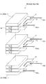
- FIG. 1A is an external perspective view illustrating a fuel cell as an example of a laminated battery to which an internal resistance measuring device according to the present invention is applied.
- FIG. 1B is an exploded view showing the structure of a power generation cell of a fuel cell as an example of a laminated battery to which an internal resistance measuring device according to the present invention is applied.
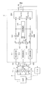
- FIG. 2 is a circuit diagram showing a first embodiment of the internal resistance measuring device for a laminated battery according to the present invention.
- FIG. 3 is a diagram illustrating details of the positive-side DC blocking unit 511, the negative-side DC blocking unit 512, the midpoint DC blocking unit 513, the positive-side AC potential difference detection unit 521, and the negative-side AC potential difference detection unit 522.
- FIG. 1A is an external perspective view illustrating a fuel cell as an example of a laminated battery to which an internal resistance measuring device according to the present invention is applied.
- FIG. 1B is an exploded view showing the structure of a power generation cell of a fuel cell
- FIG. 4 is a diagram for explaining the details of the positive power supply unit 531 and the negative power supply unit 532.
- FIG. 5 is a diagram for explaining the details of the AC adjustment unit 540.
- FIG. 6 is a diagram for explaining the details of the resistance calculation unit 550.
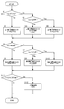
- FIG. 7 is a control flowchart executed by the controller in the first embodiment of the internal resistance measurement apparatus for a laminated battery according to the present invention.
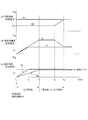
- FIG. 8 is a time chart when the controller executes control of the internal resistance measuring device of the laminated battery according to the present invention.
- FIG. 9 is a diagram for explaining the function and effect of the first embodiment.
- FIG. 10A is a diagram for explaining a mechanism of operation and effect according to the second embodiment of the internal resistance measuring device for a laminated battery according to the present invention.
- FIG. 10A is a diagram for explaining a mechanism of operation and effect according to the second embodiment of the internal resistance measuring device for a laminated battery according to the present invention.
- FIG. 10B is a diagram for explaining the mechanism of the operational effects according to the second embodiment of the internal resistance measuring device for a laminated battery according to the present invention.
- FIG. 11 is a diagram illustrating a specific configuration of the second embodiment.
- FIG. 12 is a circuit diagram showing a second embodiment of the internal resistance measuring device for a laminated battery according to the present invention.
- FIG. 13 is a circuit diagram showing a third embodiment of the internal resistance measuring device for a laminated battery according to the present invention.
- FIG. 14 is a control flowchart executed by the controller in the third embodiment of the internal resistance measurement apparatus for a laminated battery according to the present invention.
- FIG. 15 is a circuit diagram showing a fourth embodiment of the internal resistance measuring device for a laminated battery according to the present invention.
- FIG. 16 is a diagram showing a fifth embodiment of the internal resistance measuring device for a laminated battery according to the present invention.
- FIG. 17 is a diagram showing a sixth embodiment of the internal resistance measuring device for a laminated battery according to the present invention.
- FIG. 18 is a specific circuit diagram of the sixth embodiment.
- FIG. 19 is a circuit diagram showing a seventh embodiment of the internal resistance measuring device for a laminated battery according to the present invention.
- FIG. 20 is a circuit diagram showing an eighth embodiment of the internal resistance measuring device for a laminated battery according to the present invention.
- FIG. 21A is a diagram showing a first modification.
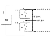
- FIG. 21B is a diagram showing a second modification.
- FIG. 1A is an external perspective view illustrating a fuel cell as an example of a laminated battery to which an internal resistance measuring device according to the present invention is applied.
- FIG. 1B is an exploded view showing the structure of a power generation cell of a fuel cell as an example of a laminated battery to which an internal resistance measuring device according to the present invention is applied.
- the fuel cell stack 1 includes a plurality of stacked power generation cells 10, a current collecting plate 20, an insulating plate 30, an end plate 40, and four tension rods 50.
- the power generation cell 10 is a unit cell of a fuel cell. Each power generation cell 10 generates an electromotive voltage of about 1 volt (V). Details of the configuration of each power generation cell 10 will be described later.
- the current collecting plate 20 is disposed outside each of the stacked power generation cells 10.
- the current collecting plate 20 is formed of a gas impermeable conductive member, for example, dense carbon.
- the current collecting plate 20 includes a positive electrode terminal 211 and a negative electrode terminal 212.
- An intermediate terminal 213 is provided between the positive terminal 211 and the negative terminal 212.
- the fuel cell stack 1 takes out and outputs electrons e ⁇ generated in each power generation cell 10 by the positive electrode terminal 211 and the negative electrode terminal 212.
- the insulating plates 30 are respectively arranged outside the current collecting plate 20.
- the insulating plate 30 is formed of an insulating member such as rubber.
- the end plate 40 is disposed outside the insulating plate 30.
- the end plate 40 is made of a rigid metal material such as steel.
- One end plate 40 (the left front end plate 40 in FIG. 1A) has an anode supply port 41a, an anode discharge port 41b, a cathode supply port 42a, a cathode discharge port 42b, and a cooling water supply port 43a.
- a cooling water discharge port 43b is provided.
- the anode discharge port 41b, the cooling water discharge port 43b, and the cathode supply port 42a are provided on the right side in the drawing.
- the cathode discharge port 42b, the cooling water supply port 43a, and the anode supply port 41a are provided on the left side in the figure.
- the tension rods 50 are arranged near the four corners of the end plate 40, respectively.
- the fuel cell stack 1 has a hole (not shown) penetrating therethrough.
- the tension rod 50 is inserted through the through hole.
- the tension rod 50 is formed of a rigid metal material such as steel.
- the tension rod 50 is insulated on the surface in order to prevent an electrical short circuit between the power generation cells 10.
- a nut (not shown because it is in the back) is screwed into the tension rod 50. The tension rod 50 and the nut tighten the fuel cell stack 1 in the stacking direction.
- a method of supplying hydrogen as the anode gas to the anode supply port 41a for example, a method of directly supplying hydrogen gas from a hydrogen storage device or a hydrogen-containing gas reformed by reforming a fuel containing hydrogen is supplied.
- the hydrogen storage device include a high-pressure gas tank, a liquefied hydrogen tank, and a hydrogen storage alloy tank.
- the fuel containing hydrogen include natural gas, methanol, and gasoline.
- Air is generally used as the cathode gas supplied to the cathode supply port 42a.
- an anode separator (anode bipolar plate) 12a and a cathode separator (cathode bipolar plate) 12b are arranged on both surfaces of a membrane electrode assembly (MEA) 11. Is the structure.
- MEA 11 has electrode catalyst layers 112 formed on both surfaces of an electrolyte membrane 111 made of an ion exchange membrane.
- a gas diffusion layer (gas diffusion layer: GDL) 113 is formed on the electrode catalyst layer 112.
- the electrode catalyst layer 112 is formed of carbon black particles carrying platinum, for example.
- the GDL 113 is formed of a member having sufficient gas diffusibility and conductivity, for example, carbon fiber.
- the anode gas supplied from the anode supply port 41a flows through this GDL 113a, reacts with the anode electrode catalyst layer 112 (112a), and is discharged from the anode discharge port 41b.
- the cathode gas supplied from the cathode supply port 42a flows through this GDL 113b, reacts with the cathode electrode catalyst layer 112 (112b), and is discharged from the cathode discharge port 42b.
- the anode separator 12a is overlaid on one side of the MEA 11 (back side in FIG. 1B) via the GDL 113a and the seal 14a.
- the cathode separator 12b is overlapped on one side (the surface in FIG. 1B) of the MEA 11 via the GDL 113b and the seal 14b.
- the seal 14 (14a, 14b) is a rubber-like elastic material such as silicone rubber, ethylene-propylene rubber (EPDM), or fluorine rubber.
- the anode separator 12a and the cathode separator 12b are formed by press-molding a separator base made of metal such as stainless steel so that a reaction gas channel is formed on one surface and alternately arranged with a reaction gas channel on the opposite surface. A cooling water flow path is formed. As shown in FIG. 1B, the anode separator 12a and the cathode separator 12b are overlapped to form a cooling water flow path.
- the MEA 11, the anode separator 12a, and the cathode separator 12b are formed with holes 41a, 41b, 42a, 42b, 43a, 43b, respectively, which are stacked to form an anode supply port (anode supply manifold) 41a, an anode discharge port.
- Anode discharge manifold 41b, cathode supply port (cathode supply manifold) 42a, cathode discharge port (cathode discharge manifold) 42b, cooling water supply port (cooling water supply manifold) 43a and cooling water discharge port (cooling water discharge manifold) 43b Is formed.
- FIG. 2 is a circuit diagram showing a first embodiment of the internal resistance measuring device for a laminated battery according to the present invention.
- the internal resistance measuring device 5 includes a positive-side DC blocking unit 511, a negative-side DC blocking unit 512, a midpoint DC blocking unit 513, a positive-side AC potential difference detection unit 521, a negative-side AC potential difference detection unit 522, Side power supply unit 531, negative electrode side power supply unit 532, AC adjustment unit 540, and resistance calculation unit 550.
- the positive side DC blocking unit 511 is connected to the positive terminal 211 of the fuel cell 1.
- the negative electrode side direct current blocking unit 512 is connected to the negative electrode terminal 212 of the fuel cell 1.
- the midpoint DC cutoff unit 513 is connected to the midway terminal 213 of the fuel cell 1. Note that the midpoint DC blocking unit 513 may not be provided as indicated by the broken line in FIG. These DC blockers block DC but flow AC.
- the DC cut-off unit is, for example, a capacitor or a transformer.
- the positive side AC potential difference detection unit 521 inputs the AC potential Va of the positive terminal 211 of the fuel cell 1 and the AC potential Vc of the midway terminal 213 and outputs an AC potential difference.
- the negative electrode side AC potential difference detection unit 522 inputs the AC potential Vb of the negative electrode terminal 212 of the fuel cell 1 and the AC potential Vc of the midway terminal 213 and outputs an AC potential difference.
- the positive side AC potential difference detection unit 521 and the negative side AC potential difference detection unit 522 are, for example, differential amplifiers (instrumentation amplifiers).
- OP amplifier operational amplifier
- the output current Io can be obtained by the input voltage Vi ⁇ proportional constant Rs without actually measuring the output current Io. Further, since the output is a current, even if an element having a phase angle such as a capacitor is interposed in the current path, the alternating current flowing through the stacked cell group and the output of the current source have the same phase. Further, it has the same phase as the input voltage Vi. Therefore, it is not necessary to consider the phase difference in calculating the resistance at the next stage, and the circuit is simple. Furthermore, even if the impedance of the capacitor in the current path varies, it is not affected by the phase change. For this reason, it is preferable to use a circuit as shown in FIG. The same applies to the negative power supply unit 532.
- the AC adjustment unit 540 can be realized by, for example, a PI control circuit as shown in FIG.
- the AC adjustment unit 540 includes a positive-side detection circuit 5411, a positive-side subtractor 5421, a positive-side integration circuit 5431, a positive-side multiplier 5451, a negative-side detection circuit 5412, a negative-side subtracter 5422, and a negative-side Integrating circuit 5432, negative multiplier 5542, reference voltage 544, and AC signal source 546 are included.
- the positive electrode side detection circuit 5411 removes an unnecessary signal from the AC potential Va on the wiring of the positive electrode side power supply unit 531 connected to the positive electrode terminal 211 of the laminated battery 1 and converts it into a DC signal.
- the positive side subtractor 5421 detects the difference between the DC signal and the reference voltage 544.
- the positive integration circuit 5431 averages or adjusts the sensitivity of the signal output from the positive subtractor 5421.
- the positive multiplier 5451 modulates the amplitude of the AC signal source 546 with the output of the positive integration circuit 5431.
- the AC adjustment unit 540 generates a command signal to the positive power supply unit 531 in this way. Similarly, AC adjustment unit 540 generates a command signal to negative power supply unit 532.
- the AC potentials Va and Vb are both controlled to a predetermined level by increasing / decreasing the outputs of the positive power supply unit 531 and the negative power supply unit 532 according to the command signal generated in this way. As a result, the alternating potentials Va and Vb are equipotential.
- an analog arithmetic IC is taken as an example in the circuit configuration.
- the AC potential Va (Vb) may be digitally converted by an AD converter and then configured by a digital control circuit.
- the resistance calculation unit 550 includes an AD converter 551 and a microcomputer chip 552.
- the AD converter 551 converts the alternating current (I1, I2) and the alternating voltage (V1, V2), which are analog signals, into digital numerical signals and transfers them to the microcomputer chip 552.
- the microcomputer chip 552 stores in advance a program for calculating the internal resistance Rn and the internal resistance R of the entire laminated battery.
- the microcomputer chip 552 sequentially calculates at predetermined minute time intervals or outputs a calculation result in response to a request from the controller 6.
- the internal resistance Rn and the internal resistance R of the entire laminated battery are calculated by the following formula.
- the resistance calculation unit 550 may be realized by an analog calculation circuit using an analog calculation IC. According to the analog arithmetic circuit, it is possible to output a resistance value change which is continuous in time.
- FIG. 7 is a control flowchart executed by the controller in the first embodiment of the internal resistance measuring apparatus for a laminated battery according to the present invention.
- step S1 the controller determines whether or not the positive AC potential Va is greater than a predetermined value. If the determination result is negative, the controller proceeds to step S2, and if the determination result is positive, the controller proceeds to step S3.
- step S2 the controller determines whether or not the positive AC potential Va is smaller than a predetermined value. If the determination result is negative, the controller proceeds to step S4, and if the determination result is positive, the controller proceeds to step S5.
- step S3 the controller decreases the output of the positive power supply unit 531. As a result, the positive AC potential Va decreases.
- step S4 the controller maintains the output of the positive power supply unit 531. As a result, the positive AC potential Va is maintained.
- step S5 the controller increases the output of the positive power supply unit 531. As a result, the positive AC potential Va increases.
- step S6 the controller determines whether or not the negative AC potential Vb is greater than a predetermined value. If the determination result is negative, the controller proceeds to step S7, and if the determination result is positive, the controller proceeds to step S8.
- step S7 the controller determines whether or not the negative electrode AC potential Vb is smaller than a predetermined value. If the determination result is negative, the controller proceeds to step S9. If the determination result is positive, the controller proceeds to step S10.
- step S8 the controller decreases the output of the negative power source unit 532. As a result, the negative AC potential Vb decreases.
- step S9 the controller maintains the output of the negative power supply unit 532. As a result, the negative AC potential Vb is maintained.
- step S10 the controller increases the output of the negative power source unit 532. This increases the negative AC potential Vb.
- step S11 the controller determines whether or not the positive AC potential Va and the negative AC potential Vb are predetermined values. If the determination result is positive, the controller proceeds to step S12. If the determination result is negative, the controller exits the process.
- step S12 the controller calculates a resistance value based on the above-described equations (1-1) and (1-2).
- FIG. 8 is a time chart when the controller executes control of the internal resistance measuring device of the laminated battery according to the present invention.
- step number is also written so that the correspondence with the flowchart is easy to understand.
- the controller starts control.
- the controller processes steps S1, S2, S4, S6, S7, S9, S11, and S12. .
- the positive side alternating current I1 and the negative side alternating current I2 are maintained.
- the positive side internal resistance value R1 and the negative side internal resistance value R2 are calculated. Then, the positive internal resistance value R1 and the negative internal resistance value R2 are added together to obtain the overall internal resistance R.
- the controller repeats steps S1, S2, S4, S6, S8, S11, and S12.
- the negative-side AC current I2 is lowered as the negative-side internal resistance value R2 increases, so the negative-side AC potential is maintained at the same level as the positive-side AC potential. Therefore, the internal resistance is calculated even in this state.
- the negative side internal resistance value coincides with the positive side internal resistance value (FIG. 8A).
- the controller repeats steps S1, S2, S4, S6, S7, S9, S11, and S12. By processing in this way, the positive side AC potential and the negative side AC potential are maintained at the same level (FIG. 8C), and the internal resistance is calculated.
- FIG. 9 is a diagram for explaining the function and effect of the first embodiment.
- a difference (DC potential difference Vdc) occurs between the positive electrode and the negative electrode.
- an alternating current is output from the positive power supply unit 531 and the negative power supply unit 532 in accordance with a command from the AC adjustment unit 540.
- the alternating current output from the positive electrode side power supply unit 531 is output to the positive electrode of the stacked battery (fuel cell) via the positive electrode side direct current cut-off unit 511, and the positive electrode side via the intermediate terminal 213 and the intermediate point direct current cut-off unit 513. It flows to the AC potential difference detection unit 521.
- This AC potential difference V ⁇ b> 1 is detected by the positive side AC potential difference detection unit 521.
- the AC adjustment unit 540 is configured so that the difference between the positive side AC potential difference V1 and the negative side AC potential difference V2 (V1 ⁇ V2; equal to Va ⁇ Vb) of the stacked battery (fuel cell) is always small. And the negative power supply 532 is adjusted.
- the output V1 of the positive-side AC potential difference detection unit 521, the output V2 of the negative-side AC potential difference detection unit 522, the AC current I1 of the positive-side power supply unit 531 and the AC current I2 of the negative-side power supply unit 532 The internal resistance R1 on the positive electrode side and the internal resistance R2 on the negative electrode side of the fuel cell 1 are calculated by applying Ohm's law.
- the AC potentials of the positive terminal 211 and the negative terminal 212 are the same. Therefore, even if a load device (such as a traveling motor) is connected to the positive electrode terminal 211 and the negative electrode terminal 212, it is possible to prevent the alternating current from leaking to the load device.
- a load device such as a traveling motor
- the AC current value flowing through the internal resistance measurement target fuel cell
- the AC current value output from the power source so that the AC current flowing through the measurement target can be accurately detected. Since the positive-side internal resistance value R1 and the negative-side internal resistance value R2 of the laminated battery are obtained based on this alternating current, the positive-side internal resistance value R1 and the negative-side internal resistance value R2 of the operating laminated battery are determined as the state of the load device. Thus, the internal resistance value R of the entire laminated battery can be accurately measured.
- FIG. 10A and FIG. 10B are diagrams for explaining the mechanism of action and effect according to the second embodiment of the internal resistance measuring device of the laminated battery according to the present invention.
- the AC potential difference detection units 521 and 522 and the power supply units 531 and 532 are connected to the fuel cell 1 through one path. However, in this embodiment, they are connected to the fuel cell 1 through different paths. I did it. This improves the detection accuracy of the internal resistance. The reason will be described below.
- the potential Vx of the fuel cell 1 is expressed by the following equation.
- the voltage Vi detected by the AC potential difference detection unit 521 is added with the error voltage corresponding to the wiring resistance Rw, the contact resistance Rc at the connection point, and the AC current to the potential Vx to be originally detected. Therefore, the measurement error err is expressed by the following equation.
- the resistance Rx to be measured is generally large for a small battery or the like, the contact resistance Rc and the wiring resistance Rw can be ignored and there is no practical problem.
- the contact resistance Rc and the wiring resistance Rw can be ignored and there is no practical problem.
- for a large battery generally [wiring resistance Rw> measurement resistance Rx]. Become a relationship. In this case, it is necessary to connect to each stacked cell group by a four-terminal method.
- the AC potential difference detection unit and the power supply unit are connected by different paths.
- the contact resistance Rc and the wiring resistance Rw of the AC voltage detection line 501a act so as to divide the voltage Vx to be detected by the input resistance Ri of the AC potential difference detection unit 521.
- FIG. 11 is a diagram showing a specific configuration of the second embodiment.
- a part of the separator (bipolar plate) 12 of the power generation cell 10 constituting the fuel cell 1 is extended to provide a connection site.
- FIG. 12 is a circuit diagram showing a second embodiment of the internal resistance measuring device for a laminated battery according to the present invention.
- the positive electrode side AC potential difference detection unit 521 is connected to the positive electrode side separator (bipolar plate) of the fuel cell 1 through the capacitor 511a.
- the positive-side power source unit 531 is connected to the same separator (bipolar plate) as the positive-side AC potential difference detection unit 521 is connected via a capacitor 511 through a path 501 different from the path 501a of the positive-side AC potential difference detection unit 521. Connect to.
- the negative electrode side AC potential difference detection unit 522 is connected to a separator (bipolar plate) on the negative electrode side of the fuel cell 1 through the capacitor 512a.
- the negative-side power source unit 532 is connected to the same separator (bipolar plate) as the negative-side AC potential difference detection unit 522 is connected through a capacitor 512 through a path 502a different from the path 502a of the negative-side AC potential difference detection unit 522. Connect to.
- the ground line 503 is connected to a separator (bipolar plate) in the middle of the fuel cell 1 through a capacitor 513. Further, the positive-side AC potential difference detecting unit 521 and the negative-side AC potential difference detecting unit 522 are connected to the same separator (bipolar plate) as the ground line 503 is connected through a capacitor 513a through a path 503a different from the ground line 503. Connect to.
- the command signal of the AC adjustment unit 540 is proportional to the output signal in the positive power supply unit 531 and the negative power supply unit 532, and based on this command signal, the AC current value (I1, I2) is obtained.
- the present embodiment it is possible to greatly reduce the influence of resistance variation due to the magnitude of wiring resistance or contact resistance, temperature, terminal surface oxidation, or the like. For this reason, the degree of freedom in designing the laminated battery side and the signal wiring is high, and the internal resistance of each laminated cell group can be accurately detected at low cost.
- the circuit can be simplified.
- FIG. 13 is a circuit diagram showing a third embodiment of the internal resistance measuring device for a laminated battery according to the present invention.
- the AC power supply unit 570 is connected to a separator (bipolar plate) in the middle of the fuel cell 1 via the capacitor 513. Further, the positive-side AC potential difference detection unit 521 is connected to the same separator (bipolar plate) as that to which the AC power supply unit 570 is connected through a capacitor 513a through a path 503a different from the path 503 of the AC power supply unit 570. .
- the positive-side AC current detection unit 531a is connected to the positive-side AC potential difference detection unit 521 via a variable resistor Ra, a variable capacitor Ca, and a capacitor 511, and is connected to a path 501 different from the path 501a of the positive-side AC potential difference detection unit 521. Connect to the same separator (bipolar plate) as you do.
- the negative-side AC current detection unit 532a is connected to the same separator (bipolar plate) to which the capacitor 512a is connected through the fixed resistor Rf and the capacitor 512 through a path 502 different from the path 502a of the capacitor 512a.
- the alternating current detector 531a As 532a, a current-voltage conversion circuit using an OP amplifier, a current transformer (CT) AC current sensor, or the like can be used.
- One end of the AC adjustment unit 540a is connected between the capacitor 511a and the positive-side AC potential difference detection unit 521. The other end is connected to the capacitor 512a.
- the AC adjusting unit 540a can input the positive AC potential Va and the negative AC potential Vb of the fuel cell 1.
- the AC adjustment unit 540a adjusts the variable resistor Ra and the variable capacitor Ca.
- FIG. 14 is a control flowchart executed by a controller in the third embodiment of the internal resistance measuring device for a laminated battery according to the present invention.
- step S1 the controller determines whether or not the initial value has been set. If the determination result is negative (initial value has not been set), the controller proceeds to step S2. If the determination result is positive (initial value has been set), the controller proceeds to step S4. .
- step S2 the controller sets the adjustment amount N of the variable resistor Ra and the adjustment amount M of the variable capacitor Ca.
- 1 is set as an example.
- step S3 the controller calculates a comparative potential difference Vp by subtracting the negative AC potential Vb from the positive AC potential Va.
- step S4 the controller determines whether or not to adjust the variable resistance Ra. If the determination result is affirmative, the controller proceeds to step S5, and if the determination result is negative, the controller proceeds to step S11.
- step S5 the controller updates the variable resistance value Ra by adding the adjustment amount N to the resistance value Ra of the variable resistance.
- step S6 the controller calculates a potential difference Vn by subtracting the negative AC potential Vb from the positive AC potential Va.
- step S7 the controller determines whether or not the potential difference Vn is smaller than the comparison potential difference Vp. If the determination result is negative, the controller proceeds to step S8. If the determination result is positive, the controller proceeds to step S9.
- step S8 the controller reverses the polarity of the adjustment amount N and exits the process once.
- step S9 the controller determines whether or not the potential difference Vn is minimized. If the determination result is affirmative, the controller proceeds to step S10. If the determination result is negative, the controller temporarily exits the process.
- step S10 the controller updates the comparison potential difference Vp with the potential difference Vn at that time.
- step S11 the controller adds the adjustment amount M to the variable capacitor capacitance Ca to update the variable capacitor capacitance Ca.
- step S12 the controller calculates a potential difference Vn by subtracting the negative AC potential Vb from the positive AC potential Va.
- step S13 the controller determines whether or not the potential difference Vn is smaller than the comparison potential difference Vp. If the determination result is negative, the controller proceeds to step S14, and if the determination result is positive, the controller proceeds to step S15.
- step S14 the controller reverses the polarity of the adjustment amount M and once exits the process.
- step S15 the controller determines whether or not the potential difference Vn is minimized. If the determination result is affirmative, the controller proceeds to step S16. If the determination result is negative, the controller temporarily exits the process.
- step S16 the controller updates the comparison potential difference Vp with the potential difference Vn at that time.
- step S17 the controller calculates a resistance value based on the above-described equations (1-1) and (1-2).
- initial values are set (S1 ⁇ S2 ⁇ S3).
- variable resistance Ra is first adjusted.
- the variable resistance value Ra is adjusted (S4), the potential difference Vn is calculated (S5). If the potential difference does not decrease, the polarity of the adjustment amount N is reversed (S8). Determine (S9).
- the variable resistance value Ra is adjusted to the minimum value.
- the comparison potential difference Vp is updated with the potential difference Vn at that time (S10).
- variable capacitor capacity Ca is adjusted.
- the variable capacitor capacitance Ca is adjusted (S11), the potential difference Vn is calculated (S12). If the potential difference does not decrease, the polarity of the adjustment amount M is reversed (S14). Determination is made (S15).
- the variable capacitor capacitance Ca is adjusted to the minimum value.
- the comparison potential difference Vp is updated with the potential difference Vn at that time (S16).
- the AC voltage amplitudes at both ends of each stacked cell group are necessarily the same. Therefore, the same effects as those in the first embodiment and the second embodiment can be obtained. That is, since the alternating current value flowing through the internal resistance measurement target (fuel cell) matches the alternating current value output from the power source, the alternating current flowing through the measurement target can be accurately detected. And since internal resistance of a laminated battery is calculated
- the AC potential difference detection unit may be provided on either the positive electrode side or the negative electrode side.
- the AC potential difference detection unit 521 is provided on the positive electrode side. Therefore, the circuit can be simplified.
- FIG. 15 is a circuit diagram showing a fourth embodiment of the internal resistance measuring device for a laminated battery according to the present invention.
- the AC power supply unit 570 is connected to a separator (bipolar plate) in the middle of the fuel cell 1 via the capacitor 513.
- the positive-side AC potential difference detection unit 521 and the negative-side AC potential difference detection unit 522 are the same separator as the AC power supply unit 570 is connected to via the capacitor 513a through a path 503a different from the path 503 of the AC power supply unit 570. Connect to (bipolar plate).
- the positive polarity inversion amplifier 540b is connected to the same separator (bipolar plate) as the positive AC potential difference detection unit 521 is connected via a capacitor 511 through a path 501 different from the path 501a of the positive AC potential difference detection unit 521. ).
- the negative polarity-side inversion amplifier 540c is connected to the same separator (bipolar plate) as the negative-side AC potential difference detection unit 522 is connected via the capacitor 512 through a path 502 different from the path 502a of the negative-side AC potential difference detection unit 522. ).
- the polarity inverting amplifier 540b As the 540c, an inverting amplifier circuit using an OP amplifier, a bootstrap circuit, an active noise cancellation circuit, or the like can be applied.
- the alternating current flowing through each stacked cell group is detected by the alternating current detection units 531a and 532a, and the alternating voltage across the stacked cell group is detected by the alternating potential difference detection units 521 and 522 connected to the alternating voltage detection line.
- the circuit can be simplified.
- FIG. 16 is a diagram showing a fifth embodiment of the internal resistance measuring device for a laminated battery according to the present invention.
- connection switch 580 In each of the above embodiments, one connection is made.
- halfway points are sequentially switched. That is, the halfway point is sequentially switched by the connection switch 580.
- the resistance of the currently connected cell can be calculated by comparing the current measured value with the previous measured value. Therefore, the internal resistance can be measured for each cell. This makes it possible to monitor internal resistance distribution in the stacking direction, local cell degradation, and the like.
- FIG. 17 is a diagram showing a sixth embodiment of the internal resistance measuring device for a laminated battery according to the present invention.
- the AC potential difference detection unit and the power source unit are connected to a common separator (bipolar plate).
- a common separator bipolar plate
- it connects to another bipolar plate separated by at least one.
- the positive power supply unit 531 is connected to the bipolar plate 501 on the positive electrode side of the fuel cell 1 through the capacitor 511.
- the positive-side AC potential difference detection unit 521 is connected to a bipolar plate 501a different from the bipolar plate 501 through a capacitor 511a.
- the positive-side AC potential difference detection unit 521 is connected to a bipolar plate 5031a different from the bipolar plate 503 to which the ground line is connected via a capacitor 5131a.
- the negative electrode side power supply unit 532 is connected to the bipolar plate 502 on the negative electrode side of the fuel cell 1 through the capacitor 512.
- the negative-side AC potential difference detection unit 522 is connected to a bipolar plate 502a different from the bipolar plate 502 via a capacitor 512a. Further, the negative AC potential difference detection unit 522 is connected to a bipolar plate 5032a different from the bipolar plate 503 to which the ground line is connected via a capacitor 5132a.
- the same effect as that of the second embodiment can be obtained. Since the space occupied by the connection terminals can be reduced, the size can be reduced.
- the cell resistance between the bipolar plate 501 and the bipolar plate 501a, the cell resistance between the bipolar plate 502 and the bipolar plate 502a, the bipolar plate 503 and the bipolar plate 5031a The cell resistance between the two and the cell resistance between the bipolar plate 503 and the bipolar plate 5032a are both outside the range of AC voltage detection and cannot be detected.
- the number of stacked layers is large, such as a large-sized stacked battery, or when the resistance variation between cells is uniform, there is no problem because the average cell resistance per cell can be obtained and corrected from the number of cells in the detection range. .
- FIG. 19 is a circuit diagram showing a seventh embodiment of the internal resistance measuring device for a laminated battery according to the present invention.
- the AC potential difference detection unit and the power supply unit are connected to a common separator (bipolar plate). Connect to bipolar plate.
- the AC potential difference detection unit is provided only on the positive electrode side, and this positive electrode side AC potential difference detection unit is connected to the bipolar plate 5031a in FIG.
- the AC potential difference detection unit connected to the bipolar plate 5032a in FIG. 17 is not necessary.
- the AC voltage amplitudes at both ends of each stacked cell group are inevitably the same as in the third embodiment.
- the AC current value flowing through the internal resistance measurement target matches the AC current value output from the power source, so that the AC current flowing through the measurement target can be accurately detected.
- the internal resistance of a laminated battery is calculated
- FIG. 20 is a circuit diagram showing an eighth embodiment of the internal resistance measuring device for a laminated battery according to the present invention.
- This embodiment is basically the same as the fourth embodiment (FIG. 15). However, in the fourth embodiment (FIG. 15), the AC potential difference detection unit and the power supply unit (or AC current detection unit) are connected to a common separator (bipolar plate). Connect to a separate bipolar plate. A specific circuit diagram is shown in FIG.
- the positive polarity inversion amplifier 540b is connected to the bipolar plate 501 on the positive side of the fuel cell 1 through the capacitor 511.
- the positive-side AC potential difference detection unit 521 is connected to a bipolar plate 501a different from the bipolar plate 501 through a capacitor 511a.
- the positive-side AC potential difference detection unit 521 is connected to a bipolar plate 5031a different from the bipolar plate 503 to which the ground line is connected via a capacitor 5131a.
- the negative polarity polarity inverting amplifier 540 c is connected to the bipolar plate 502 on the negative polarity side of the fuel cell 1 through the capacitor 512.
- the negative-side AC potential difference detection unit 522 is connected to a bipolar plate 502a different from the bipolar plate 502 via a capacitor 512a. Further, the negative AC potential difference detection unit 522 is connected to a bipolar plate 5032a different from the bipolar plate 503 to which the ground line is connected via a capacitor 5132a.
- the polarity of the alternating voltage detected at the laminated battery output terminal is reversed and returned to the respective laminated battery output terminals, so that the alternating voltage amplitude at the laminated battery output terminal is It is forcibly canceled (zeroed).
- the AC voltage amplitudes at both ends of the laminated battery become zero and become equipotential.
- the alternating current flowing through each stacked cell group is detected by the alternating current detection units 531a and 532a, and the alternating voltage across the stacked cell group is detected by the alternating potential difference detection units 521 and 522 connected to the alternating voltage detection line. Therefore, according to the present embodiment, since the voltage comparison function by the AC adjustment unit 540 is unnecessary, the circuit can be simplified. Further, the space occupied by the connection terminals can be reduced, so that the size can be reduced.
- a battery in which a resistor 2 is further connected in series may be used as an internal resistance measurement target.
- the end of the resistor 2 in FIG. 21A is regarded as the positive electrode of the above embodiment
- the positive electrode of the laminated battery 1 in FIG. 21A is regarded as a midpoint of the above embodiment
- the end of the laminated battery 1 in FIG. 21A is regarded as a midpoint of the above embodiment
- the negative electrode is regarded as the negative electrode of the above embodiment.
- the internal resistance value of the entire laminated battery in FIG. 21A is obtained as R2. Even if it does in this way, the internal resistance value of the whole laminated battery can be measured correctly.
- a battery in which a laminated battery 1-2 is further connected in series to the laminated battery 1-1 may be used as an internal resistance measurement target.
- the positive electrode of the multilayer battery 1-1 is regarded as the positive electrode of the above embodiment
- the midpoint between the multilayer battery 1-1 and the multilayer battery 1-2 is regarded as the midpoint of the above embodiment.
- the negative electrode of the battery 1-2 is regarded as the negative electrode of the above embodiment.
- the internal resistance value of the laminated battery 1-1 is obtained as R1
- the internal resistance value of the laminated battery 1-2 is obtained as R2. Even in this way, the internal resistance values of the laminated battery 1-1 and the laminated battery 1-2 can be accurately measured.
- a fuel cell is given as an example of a laminated battery, but a battery such as a lithium ion battery may be used. That is, it can be applied to any battery in which a plurality of power generation elements are stacked. Even with such a battery, it is desirable to be able to operate efficiently if the internal resistance can be measured.
- halfway points may be sequentially switched as in the fifth embodiment. Even if it does in this way, the effect similar to 5th Embodiment can be acquired.
Landscapes
- Engineering & Computer Science (AREA)
- Manufacturing & Machinery (AREA)
- Chemical & Material Sciences (AREA)
- Chemical Kinetics & Catalysis (AREA)
- Electrochemistry (AREA)
- General Chemical & Material Sciences (AREA)
- Life Sciences & Earth Sciences (AREA)
- Sustainable Development (AREA)
- Sustainable Energy (AREA)
- Physics & Mathematics (AREA)
- General Physics & Mathematics (AREA)
- Measurement Of Resistance Or Impedance (AREA)
- Fuel Cell (AREA)
- Secondary Cells (AREA)
Abstract
Description
図1Aは、本発明による内部抵抗測定装置を適用する積層電池の一例としての燃料電池を説明する外観斜視図である。図1Bは、本発明による内部抵抗測定装置を適用する積層電池の一例としての燃料電池の発電セルの構造を示す分解図である。

正極側電源部531から出力された交流電流は、正極側直流遮断部511を介して、積層電池(燃料電池)の正極に出力され、中途端子213及び中途点直流遮断部513を介して正極側交流電位差検出部521に流れる。このとき内部抵抗及び供給電流に応じた交流電位差V1(V1=Va-Vc)が生じる。この交流電位差V1が正極側交流電位差検出部521で検出される。
図10A及び図10Bは、本発明による積層電池の内部抵抗測定装置の第2実施形態による作用効果のメカニズムを説明する図である。


図13は、本発明による積層電池の内部抵抗測定装置の第3実施形態を示す回路図である。
図15は、本発明による積層電池の内部抵抗測定装置の第4実施形態を示す回路図である。
図16は、本発明による積層電池の内部抵抗測定装置の第5実施形態を示す図である。
図17は、本発明による積層電池の内部抵抗測定装置の第6実施形態を示す図である。
図19は、本発明による積層電池の内部抵抗測定装置の第7実施形態を示す回路図である。
図20は、本発明による積層電池の内部抵抗測定装置の第8実施形態を示す回路図である。
Claims (12)
- 複数の発電要素が積層される積層電池を少なくとも含む内部抵抗測定対象に接続されて、内部抵抗測定対象に交流電流を出力する交流電源部と、
前記内部抵抗測定対象の正極側の負荷装置に接続される部分の電位から中途部分の電位を引いて求めた電位差である正極側交流電位差と、前記内部抵抗測定対象の負極側の負荷装置に接続される部分の電位から前記中途部分の電位を引いて求めた電位差である負極側交流電位差と、が一致するように交流電流を調整する交流調整部と、
前記調整された交流電流及び交流電位差に基づいて前記積層電池の抵抗を演算する抵抗演算部と、
を含む積層電池の内抵抗測定装置。 - 請求項1に記載の積層電池の内部抵抗測定装置において、
前記内部抵抗測定対象は、前記積層電池であって、
前記交流調整部は、前記積層電池の正極側の負荷装置に接続される部分の電位から中途部分の電位を引いて求めた電位差である正極側交流電位差と、前記積層電池の負極側の負荷装置に接続される部分の電位から前記中途部分の電位を引いて求めた電位差である負極側交流電位差と、が一致するように交流電流を調整する、
積層電池の内部抵抗測定装置。 - 請求項1又は請求項2に記載の積層電池の内部抵抗測定装置において、
前記交流電源部は、前記内部抵抗測定対象の正極側接続部分に直流遮断部を介して接続されて内部抵抗測定対象に交流電流を出力する正極側電源部と、前記内部抵抗測定対象の負極側接続部分に直流遮断部を介して接続されて内部抵抗測定対象に交流電流を出力する負極側電源部と、を含み、
前記交流調整部は、前記正極側交流電位差と前記負極側交流電位差とが一致するように、前記正極側電源部及び前記負極側電源部を調整する、
積層電池の内部抵抗測定装置。 - 請求項3に記載の積層電池の内部抵抗測定装置において、
前記正極側接続部分には、前記正極側電源部が接続される経路とは異なる経路で前記正極側交流電位差を検出する正極側交流電位差検出器が直流遮断部を介して接続され、
前記負極側接続部分には、前記負極側電源部が接続される経路とは異なる経路で前記負極側交流電位差を検出する負極側交流電位差検出器が直流遮断部を介して接続され、
前記中途部分には、接地線が直流遮断部を介して接続されるとともに、その接続経路とは異なる経路で前記正極側交流電位差検出器及び前記負極側交流電位差検出器が直流遮断部を介して接続される、
積層電池の内部抵抗測定装置。 - 請求項3に記載の積層電池の内部抵抗測定装置において、
前記正極側接続部分から少なくともひとつの発電要素を隔てた部分には、前記正極側交流電位差を検出する正極側交流電位差検出器が直流遮断部を介して接続され、
前記負極側接続部分から少なくともひとつの発電要素を隔てた部分には、前記負極側交流電位差を検出する負極側交流電位差検出器が直流遮断部を介して接続され、
前記中途部分には、接地線が直流遮断部を介して接続され、
前記中途部分から少なくともひとつの発電要素を隔てた正極側の部分には、前記正極側交流電位差検出器が直流遮断部を介して接続され、
前記中途部分から少なくともひとつの発電要素を隔てた負極側の部分には、前記負極側交流電位差検出器が直流遮断部を介して接続される、
積層電池の内部抵抗測定装置。 - 請求項1又は請求項2に記載の積層電池の内部抵抗測定装置において、
前記内部抵抗測定対象の正極側接続部分及び負極側接続部分の一方に直流遮断部を介して接続される可変抵抗及び可変コンデンサーと、
前記内部抵抗測定対象の正極側接続部分及び負極側接続部分の他方に直流遮断部を介して接続される固定抵抗と、
前記正極側接続部分又は前記負極側接続部分のいずれか一方と前記中途部分とに直流遮断部を介して接続されて、前記正極側交流電位差又は前記負極側交流電位差を検出する交流電位差検出器と、
を含み、
前記交流電源部は、前記中途部分に直流遮断部を介して接続されて中途部分に交流電流を出力し、
前記交流調整部は、前記正極側交流電位と前記負極側交流電位とが一致するように、前記可変抵抗及び可変コンデンサーを調整する、
積層電池の内部抵抗測定装置。 - 請求項6に記載の積層電池の内部抵抗測定装置において、
前記正極側接続部分には、前記可変抵抗及び前記固定抵抗の一方が接続される経路とは異なる経路が、前記正極側交流電位を前記交流調整部に出力するように直流遮断部を介して接続され、
前記負極側接続部分には、前記可変抵抗及び前記固定抵抗の他方が接続される経路とは異なる経路が、前記負極側交流電位を前記交流調整部に出力するように直流遮断部を介して接続され、
前記中途部分には、前記交流電源部が接続される経路とは異なる経路で前記交流電位差検出器が直流遮断部を介して接続される、
積層電池の内部抵抗測定装置。 - 請求項6に記載の積層電池の内部抵抗測定装置において、
前記正極側接続部分から少なくともひとつの発電要素を隔てた部分には、前記正極側交流電位を前記交流調整部に出力する経路が直流遮断部を介して接続され、
前記負極側接続部分から少なくともひとつの発電要素を隔てた部分には、前記負極側交流電位を前記交流調整部に出力する経路が直流遮断部を介して接続され、
前記中途部分から少なくともひとつの発電要素を隔てた部分には、前記交流電位差検出器が直流遮断部を介して接続される、
積層電池の内部抵抗測定装置。 - 請求項1又は請求項2に記載の積層電池の内部抵抗測定装置において、
前記交流電源部は、前記中途部分に直流遮断部を介して接続されて中途部分に交流電流を出力し、
前記交流調整部は、前記内部抵抗測定対象の正極側接続部分に直流遮断部を介して接続されて内部抵抗測定対象の正極側接続部分の電位をゼロする正極側調整部と、前記内部抵抗測定対象の負極側接続部分に直流遮断部を介して接続されて内部抵抗測定対象の負極側接続部分の電位をゼロにする負極側調整部と、を含む、
積層電池の内部抵抗測定装置。 - 請求項9に記載の積層電池の内部抵抗測定装置において、
前記正極側接続部分には、前記正極側調整部が接続される経路とは異なる経路で前記正極側交流電位差を検出する正極側交流電位差検出器が直流遮断部を介して接続され、
前記負極側接続部分には、前記負極側調整部が接続される経路とは異なる経路で前記負極側交流電位差を検出する負極側交流電位差検出器が直流遮断部を介して接続され、
前記中途部分には、前記交流電源部が接続される経路とは異なる経路で前記正極側交流電位差検出器及び前記負極側交流電位差検出器が直流遮断部を介して接続される、
積層電池の内部抵抗測定装置。 - 請求項9に記載の積層電池の内部抵抗測定装置において、
前記正極側接続部分から少なくともひとつの発電要素を隔てた部分には、前記正極側交流電位差を検出する正極側交流電位差検出器が直流遮断部を介して接続され、
前記負極側接続部分から少なくともひとつの発電要素を隔てた部分には、前記負極側交流電位差を検出する負極側交流電位差検出器が直流遮断部を介して接続され、
前記中途部分から少なくともひとつの発電要素を隔てた正極側の部分には、前記正極側交流電位差検出器が直流遮断部を介して接続され、
前記中途部分から少なくともひとつの発電要素を隔てた負極側の部分には、前記負極側交流電位差検出器が直流遮断部を介して接続される、
積層電池の内部抵抗測定装置。 - 請求項1から請求項11までのいずれか1項に記載の積層電池の内部抵抗測定装置において、
前記中途部分を順次切り替える接続切替変更器をさらに含む、
積層電池の内部抵抗測定装置。
Priority Applications (9)
| Application Number | Priority Date | Filing Date | Title |
|---|---|---|---|
| JP2012547750A JP5708658B2 (ja) | 2010-12-10 | 2011-11-09 | 積層電池の内部抵抗測定装置及び内部抵抗測定方法 |
| CN201180060003.9A CN103261898B (zh) | 2010-12-10 | 2011-11-09 | 层叠电池的内阻测量装置以及内阻测量方法 |
| EP11846084.9A EP2650689B1 (en) | 2010-12-10 | 2011-11-09 | Layered battery internal resistance measuring apparatus |
| BR112013014482-3A BR112013014482B1 (pt) | 2010-12-10 | 2011-11-09 | dispositivo de medição de resistência interna e método de medição de resistência interna para bateria empilhada |
| RU2013131786/28A RU2536780C1 (ru) | 2010-12-10 | 2011-11-09 | Устройство и способ измерения внутреннего сопротивления для пакетированной батареи |
| MX2013006438A MX2013006438A (es) | 2010-12-10 | 2011-11-09 | Dispositivo de medicion de resistencia interna y metodo para bateria aplilada. |
| US13/992,397 US9366731B2 (en) | 2010-12-10 | 2011-11-09 | Internal resistance measurement device and method for stacked battery |
| PH1/2013/501174A PH12013501174A1 (en) | 2010-12-10 | 2011-11-09 | Internal resistance measurement device and method for stacked battery |
| KR1020137017917A KR101481359B1 (ko) | 2010-12-10 | 2011-11-09 | 적층 전지의 내부 저항 측정 장치 및 내부 저항 측정 방법 |
Applications Claiming Priority (2)
| Application Number | Priority Date | Filing Date | Title |
|---|---|---|---|
| JP2010275638 | 2010-12-10 | ||
| JP2010-275638 | 2010-12-10 |
Publications (1)
| Publication Number | Publication Date |
|---|---|
| WO2012077450A1 true WO2012077450A1 (ja) | 2012-06-14 |
Family
ID=46206951
Family Applications (1)
| Application Number | Title | Priority Date | Filing Date |
|---|---|---|---|
| PCT/JP2011/075792 Ceased WO2012077450A1 (ja) | 2010-12-10 | 2011-11-09 | 積層電池の内部抵抗測定装置 |
Country Status (11)
| Country | Link |
|---|---|
| US (1) | US9366731B2 (ja) |
| EP (1) | EP2650689B1 (ja) |
| JP (1) | JP5708658B2 (ja) |
| KR (1) | KR101481359B1 (ja) |
| CN (2) | CN104614680B (ja) |
| BR (1) | BR112013014482B1 (ja) |
| MX (1) | MX2013006438A (ja) |
| MY (1) | MY173025A (ja) |
| PH (1) | PH12013501174A1 (ja) |
| RU (1) | RU2536780C1 (ja) |
| WO (1) | WO2012077450A1 (ja) |
Cited By (21)
| Publication number | Priority date | Publication date | Assignee | Title |
|---|---|---|---|---|
| WO2014057868A1 (ja) * | 2012-10-09 | 2014-04-17 | 日産自動車株式会社 | 積層電池のインピーダンス測定装置 |
| WO2014141752A1 (ja) | 2013-03-12 | 2014-09-18 | 日産自動車株式会社 | インピーダンス測定装置及びインピーダンス測定装置の制御方法 |
| WO2015029647A1 (ja) | 2013-08-29 | 2015-03-05 | 日産自動車株式会社 | 積層電池のインピーダンス測定装置および測定方法 |
| WO2015125237A1 (ja) * | 2014-02-19 | 2015-08-27 | 日産自動車株式会社 | インピーダンス測定装置及びインピーダンス測定装置の制御方法 |
| WO2015125506A1 (ja) * | 2014-02-19 | 2015-08-27 | 日産自動車株式会社 | インピーダンス測定装置及びインピーダンス測定装置の制御方法 |
| WO2015145615A1 (ja) * | 2014-03-26 | 2015-10-01 | 日産自動車株式会社 | インピーダンス測定装置及びインピーダンス測定方法 |
| WO2015145755A1 (ja) * | 2014-03-28 | 2015-10-01 | 日産自動車株式会社 | 積層電池、セパレータ及び内部抵抗測定装置の接続方法 |
| JP2015232459A (ja) * | 2014-06-09 | 2015-12-24 | 日産自動車株式会社 | インピーダンス測定装置 |
| WO2016006114A1 (ja) * | 2014-07-11 | 2016-01-14 | 日産自動車株式会社 | 燃料電池のインピーダンス測定装置および燃料電池のインピーダンス測定方法 |
| WO2016006116A1 (ja) * | 2014-07-11 | 2016-01-14 | 日産自動車株式会社 | 燃料電池のインピーダンス測定装置および燃料電池のインピーダンス測定方法 |
| JP2016014625A (ja) * | 2014-07-03 | 2016-01-28 | 日産自動車株式会社 | インピーダンス測定装置 |
| JP2016014634A (ja) * | 2014-07-03 | 2016-01-28 | 日産自動車株式会社 | インピーダンス測定装置 |
| JP2016050858A (ja) * | 2014-08-29 | 2016-04-11 | 日産自動車株式会社 | 積層電池のインピーダンス測定装置 |
| WO2016092618A1 (ja) * | 2014-12-08 | 2016-06-16 | 日産自動車株式会社 | インピーダンス測定装置及びインピーダンス測定方法 |
| WO2016125231A1 (ja) * | 2015-02-02 | 2016-08-11 | 日産自動車株式会社 | 燃料電池システム及び燃料電池システムの制御方法 |
| JP2017010620A (ja) * | 2015-06-16 | 2017-01-12 | パナソニックIpマネジメント株式会社 | 燃料電池システムおよびその運転方法 |
| JP2017219509A (ja) * | 2016-06-10 | 2017-12-14 | 日産自動車株式会社 | インピーダンス測定装置、診断装置、及びインピーダンス測定装置の測定方法 |
| CN108631394A (zh) * | 2018-04-28 | 2018-10-09 | 沈阳劲达科技有限公司 | 内阻检测传感器 |
| US10193167B2 (en) | 2015-05-21 | 2019-01-29 | Nissan Motor Co., Ltd. | Power conditioning system and control method therefor |
| WO2021048587A1 (ja) | 2019-09-13 | 2021-03-18 | 日産自動車株式会社 | 全固体リチウムイオンニ次電池システム、および全固体リチウムイオンニ次電池用充電装置 |
| CN115810775A (zh) * | 2022-11-29 | 2023-03-17 | 上海神力科技有限公司 | 一种高通用性的燃料电池电堆电压采集装置 |
Families Citing this family (6)
| Publication number | Priority date | Publication date | Assignee | Title |
|---|---|---|---|---|
| JP2015154593A (ja) * | 2014-02-14 | 2015-08-24 | ソニー株式会社 | 充放電制御装置、電池パック、電子機器、電動車両および充放電制御方法 |
| CN104166047B (zh) * | 2014-04-11 | 2016-08-17 | 东北大学 | 同步测量磁致金属熔体电阻和电势差变化的装置和方法 |
| US20160020618A1 (en) * | 2014-07-21 | 2016-01-21 | Ford Global Technologies, Llc | Fast Charge Algorithms for Lithium-Ion Batteries |
| KR101859419B1 (ko) | 2014-12-26 | 2018-05-23 | 엘지디스플레이 주식회사 | 터치 스크린 장치와 그의 구동방법 |
| CN109142872A (zh) * | 2017-06-16 | 2019-01-04 | 日本贵弥功株式会社 | 蓄电元件的电阻的测定方法以及测定装置 |
| CN113109727B (zh) * | 2021-03-29 | 2022-08-23 | 蜂巢能源科技有限公司 | 叠片式锂电池电芯内阻一致性分析方法及分析系统 |
Citations (3)
| Publication number | Priority date | Publication date | Assignee | Title |
|---|---|---|---|---|
| JPH033659U (ja) * | 1989-05-31 | 1991-01-16 | ||
| JP2008547008A (ja) * | 2005-06-23 | 2008-12-25 | ローベルト ボツシユ ゲゼルシヤフト ミツト ベシユレンクテル ハフツング | 自動車アキュムレータ用のバッテリー状態検出方法および装置 |
| JP2010078556A (ja) * | 2008-09-29 | 2010-04-08 | Nissan Motor Co Ltd | 抵抗分布検出装置及びそれを使用する燃料電池システム |
Family Cites Families (28)
| Publication number | Priority date | Publication date | Assignee | Title |
|---|---|---|---|---|
| US3753094A (en) * | 1969-07-01 | 1973-08-14 | Matsushita Electric Industrial Co Ltd | Ohmmeter for measuring the internal resistance of a battery and directly reading the measured resistance value |
| US5047722A (en) * | 1989-04-17 | 1991-09-10 | Ssmc Inc. | Apparatus for measuring internal resistance of wet cell storage batteries having non-removable cell caps |
| JPH03226688A (ja) * | 1990-01-31 | 1991-10-07 | Yuasa Battery Co Ltd | 鉛蓄電池の寿命判定方法 |
| JP3003659U (ja) * | 1994-04-28 | 1994-10-25 | アデックス株式会社 | インピーダンス測定装置 |
| US5862515A (en) * | 1996-02-16 | 1999-01-19 | Hioki Denki Kabushiki Kaisha | Battery tester |
| JPH09297165A (ja) * | 1996-03-04 | 1997-11-18 | Hioki Ee Corp | バッテリテスタ |
| JP3713828B2 (ja) * | 1996-08-12 | 2005-11-09 | ソニー株式会社 | 充電方法、充電装置及び充電制御回路 |
| JP3720555B2 (ja) * | 1997-12-15 | 2005-11-30 | ソニー株式会社 | 電池セル検査方法及び電池セル検査装置 |
| JP3598873B2 (ja) * | 1998-08-10 | 2004-12-08 | トヨタ自動車株式会社 | 二次電池の状態判定方法及び状態判定装置、並びに二次電池の再生方法 |
| JP2001351696A (ja) * | 2000-06-02 | 2001-12-21 | Hitachi Ltd | 二次電池の充放電装置 |
| JP2002267704A (ja) * | 2001-03-14 | 2002-09-18 | Hioki Ee Corp | 積層電池の内部抵抗測定方法および計測装置 |
| JP4360052B2 (ja) * | 2001-06-27 | 2009-11-11 | 株式会社ジーエス・ユアサコーポレーション | 二次電池の寿命判定装置、寿命判定方法、及び、寿命判定プログラム |
| JP2003121513A (ja) * | 2001-10-09 | 2003-04-23 | Furukawa Battery Co Ltd:The | 蓄電池内部抵抗測定方法 |
| JP3904875B2 (ja) * | 2001-10-09 | 2007-04-11 | 古河電池株式会社 | 蓄電池の内部インピーダンス測定方法 |
| JP4407874B2 (ja) * | 2001-10-09 | 2010-02-03 | 古河電池株式会社 | 蓄電池内部抵抗測定回路 |
| JP2003121516A (ja) * | 2001-10-09 | 2003-04-23 | Furukawa Battery Co Ltd:The | 蓄電池内部抵抗測定装置 |
| DE10394007T5 (de) * | 2002-12-31 | 2006-02-02 | Midtronics, Inc., Willowbrook | Vorrichtung und Verfahren zum Vorhersagen der verbleibenden Entladezeit einer Batterie |
| US7642786B2 (en) * | 2004-06-01 | 2010-01-05 | Midtronics, Inc. | Battery tester capable of identifying faulty battery post adapters |
| US7545146B2 (en) * | 2004-12-09 | 2009-06-09 | Midtronics, Inc. | Apparatus and method for predicting battery capacity and fitness for service from a battery dynamic parameter and a recovery voltage differential |
| JP2007181365A (ja) * | 2005-12-28 | 2007-07-12 | Ntt Data Ex Techno Corp | バッテリー群に対する交流電圧印加回路及び方法 |
| JP2007188767A (ja) * | 2006-01-13 | 2007-07-26 | Fujitsu Ten Ltd | バッテリ状態監視装置、バッテリ状態監視システム、及びバッテリ状態監視方法 |
| US20070194791A1 (en) * | 2006-02-17 | 2007-08-23 | Bppower Inc. | Method and apparatus for monitoring the condition of a battery by measuring its internal resistance |
| JP5563734B2 (ja) * | 2007-10-31 | 2014-07-30 | 日置電機株式会社 | 電子負荷装置および電池の内部抵抗測定装置 |
| CN201156079Y (zh) * | 2007-12-27 | 2008-11-26 | 武汉理工大学 | 一种燃料电池堆单片电池内阻与电压在线测试装置 |
| CN101477179A (zh) * | 2009-01-15 | 2009-07-08 | 艾默生网络能源有限公司 | 蓄电池内阻在线交流检测方法和系统 |
| CN201548669U (zh) * | 2009-11-24 | 2010-08-11 | 南京鼎尔特科技有限公司 | 蓄电池故障预警仪 |
| CN201594116U (zh) * | 2009-11-30 | 2010-09-29 | 比亚迪股份有限公司 | 一种电池内阻的测量装置 |
| CN101806865B (zh) * | 2010-03-29 | 2013-04-17 | 深圳睿立方智能科技有限公司 | 一种电池内阻检测装置 |
-
2011
- 2011-11-09 US US13/992,397 patent/US9366731B2/en active Active
- 2011-11-09 WO PCT/JP2011/075792 patent/WO2012077450A1/ja not_active Ceased
- 2011-11-09 EP EP11846084.9A patent/EP2650689B1/en active Active
- 2011-11-09 BR BR112013014482-3A patent/BR112013014482B1/pt not_active IP Right Cessation
- 2011-11-09 RU RU2013131786/28A patent/RU2536780C1/ru active
- 2011-11-09 MY MYPI2013002062A patent/MY173025A/en unknown
- 2011-11-09 CN CN201510036635.1A patent/CN104614680B/zh active Active
- 2011-11-09 KR KR1020137017917A patent/KR101481359B1/ko not_active Expired - Fee Related
- 2011-11-09 JP JP2012547750A patent/JP5708658B2/ja active Active
- 2011-11-09 CN CN201180060003.9A patent/CN103261898B/zh active Active
- 2011-11-09 PH PH1/2013/501174A patent/PH12013501174A1/en unknown
- 2011-11-09 MX MX2013006438A patent/MX2013006438A/es active IP Right Grant
Patent Citations (3)
| Publication number | Priority date | Publication date | Assignee | Title |
|---|---|---|---|---|
| JPH033659U (ja) * | 1989-05-31 | 1991-01-16 | ||
| JP2008547008A (ja) * | 2005-06-23 | 2008-12-25 | ローベルト ボツシユ ゲゼルシヤフト ミツト ベシユレンクテル ハフツング | 自動車アキュムレータ用のバッテリー状態検出方法および装置 |
| JP2010078556A (ja) * | 2008-09-29 | 2010-04-08 | Nissan Motor Co Ltd | 抵抗分布検出装置及びそれを使用する燃料電池システム |
Non-Patent Citations (1)
| Title |
|---|
| See also references of EP2650689A4 * |
Cited By (41)
| Publication number | Priority date | Publication date | Assignee | Title |
|---|---|---|---|---|
| JP5867615B2 (ja) * | 2012-10-09 | 2016-02-24 | 日産自動車株式会社 | 積層電池のインピーダンス測定装置 |
| CN104704381A (zh) * | 2012-10-09 | 2015-06-10 | 日产自动车株式会社 | 层叠电池的阻抗测量装置 |
| WO2014057868A1 (ja) * | 2012-10-09 | 2014-04-17 | 日産自動車株式会社 | 積層電池のインピーダンス測定装置 |
| CN104704381B (zh) * | 2012-10-09 | 2017-03-08 | 日产自动车株式会社 | 层叠电池的阻抗测量装置 |
| US20150276888A1 (en) * | 2012-10-09 | 2015-10-01 | Nissan Motor Co., Ltd. | Impedance measuring device for laminated battery |
| EP2908149A4 (en) * | 2012-10-09 | 2015-11-04 | Nissan Motor | DEVICE FOR MEASURING THE IMPEDANCE OF A LAMINATE BATTERY |
| US9529055B2 (en) | 2012-10-09 | 2016-12-27 | Nissan Motor Co., Ltd. | Impedance measuring device for laminated battery |
| WO2014141752A1 (ja) | 2013-03-12 | 2014-09-18 | 日産自動車株式会社 | インピーダンス測定装置及びインピーダンス測定装置の制御方法 |
| JP6075442B2 (ja) * | 2013-03-12 | 2017-02-08 | 日産自動車株式会社 | インピーダンス測定装置及びインピーダンス測定装置の制御方法 |
| US9450259B2 (en) | 2013-03-12 | 2016-09-20 | Nissan Motor Co., Ltd. | Impedance measuring device and control method for impedance measuring device |
| WO2015029647A1 (ja) | 2013-08-29 | 2015-03-05 | 日産自動車株式会社 | 積層電池のインピーダンス測定装置および測定方法 |
| US9874612B2 (en) | 2013-08-29 | 2018-01-23 | Nissan Motor Co., Ltd. | Apparatus and method for measuring impedance of laminated battery |
| US9817075B2 (en) | 2014-02-19 | 2017-11-14 | Nissan Motor Co., Ltd. | Impedance measuring device and control method for impedance measuring device |
| WO2015125237A1 (ja) * | 2014-02-19 | 2015-08-27 | 日産自動車株式会社 | インピーダンス測定装置及びインピーダンス測定装置の制御方法 |
| WO2015125506A1 (ja) * | 2014-02-19 | 2015-08-27 | 日産自動車株式会社 | インピーダンス測定装置及びインピーダンス測定装置の制御方法 |
| US9791518B2 (en) | 2014-02-19 | 2017-10-17 | Nissan Motor Co., Ltd. | Impedance measuring device and control method for impedance measuring device |
| JPWO2015125506A1 (ja) * | 2014-02-19 | 2017-03-30 | 日産自動車株式会社 | インピーダンス測定装置及びインピーダンス測定装置の制御方法 |
| JPWO2015125237A1 (ja) * | 2014-02-19 | 2017-03-30 | 日産自動車株式会社 | インピーダンス測定装置及びインピーダンス測定装置の制御方法 |
| WO2015145615A1 (ja) * | 2014-03-26 | 2015-10-01 | 日産自動車株式会社 | インピーダンス測定装置及びインピーダンス測定方法 |
| JPWO2015145615A1 (ja) * | 2014-03-26 | 2017-04-13 | 日産自動車株式会社 | インピーダンス測定装置及びインピーダンス測定方法 |
| US10044054B2 (en) | 2014-03-28 | 2018-08-07 | Nissan Motor Co., Ltd. | Laminated battery, separator and connection method of internal resistance measuring device |
| JPWO2015145755A1 (ja) * | 2014-03-28 | 2017-04-13 | 日産自動車株式会社 | 積層電池、セパレータ及び内部抵抗測定装置の接続方法 |
| WO2015145755A1 (ja) * | 2014-03-28 | 2015-10-01 | 日産自動車株式会社 | 積層電池、セパレータ及び内部抵抗測定装置の接続方法 |
| JP2015232459A (ja) * | 2014-06-09 | 2015-12-24 | 日産自動車株式会社 | インピーダンス測定装置 |
| JP2016014634A (ja) * | 2014-07-03 | 2016-01-28 | 日産自動車株式会社 | インピーダンス測定装置 |
| JP2016014625A (ja) * | 2014-07-03 | 2016-01-28 | 日産自動車株式会社 | インピーダンス測定装置 |
| WO2016006116A1 (ja) * | 2014-07-11 | 2016-01-14 | 日産自動車株式会社 | 燃料電池のインピーダンス測定装置および燃料電池のインピーダンス測定方法 |
| US10290885B2 (en) | 2014-07-11 | 2019-05-14 | Nissan Motor Co., Ltd. | Apparatus for measuring an impedance of fuel cell and method of measuring an impedance of fuel cell |
| JPWO2016006116A1 (ja) * | 2014-07-11 | 2017-04-27 | 日産自動車株式会社 | 燃料電池のインピーダンス測定装置および燃料電池のインピーダンス測定方法 |
| WO2016006114A1 (ja) * | 2014-07-11 | 2016-01-14 | 日産自動車株式会社 | 燃料電池のインピーダンス測定装置および燃料電池のインピーダンス測定方法 |
| JP2016050858A (ja) * | 2014-08-29 | 2016-04-11 | 日産自動車株式会社 | 積層電池のインピーダンス測定装置 |
| WO2016092618A1 (ja) * | 2014-12-08 | 2016-06-16 | 日産自動車株式会社 | インピーダンス測定装置及びインピーダンス測定方法 |
| WO2016125231A1 (ja) * | 2015-02-02 | 2016-08-11 | 日産自動車株式会社 | 燃料電池システム及び燃料電池システムの制御方法 |
| US10193167B2 (en) | 2015-05-21 | 2019-01-29 | Nissan Motor Co., Ltd. | Power conditioning system and control method therefor |
| JP2017010620A (ja) * | 2015-06-16 | 2017-01-12 | パナソニックIpマネジメント株式会社 | 燃料電池システムおよびその運転方法 |
| JP2017219509A (ja) * | 2016-06-10 | 2017-12-14 | 日産自動車株式会社 | インピーダンス測定装置、診断装置、及びインピーダンス測定装置の測定方法 |
| CN108631394A (zh) * | 2018-04-28 | 2018-10-09 | 沈阳劲达科技有限公司 | 内阻检测传感器 |
| CN108631394B (zh) * | 2018-04-28 | 2024-03-29 | 沈阳劲达科技有限公司 | 内阻检测传感器 |
| WO2021048587A1 (ja) | 2019-09-13 | 2021-03-18 | 日産自動車株式会社 | 全固体リチウムイオンニ次電池システム、および全固体リチウムイオンニ次電池用充電装置 |
| US11460510B1 (en) | 2019-09-13 | 2022-10-04 | Nissan Motor Co., Ltd. | All-solid-state lithium ion secondary battery system and charging device for all-solid-state lithium ion secondary batteries |
| CN115810775A (zh) * | 2022-11-29 | 2023-03-17 | 上海神力科技有限公司 | 一种高通用性的燃料电池电堆电压采集装置 |
Also Published As
| Publication number | Publication date |
|---|---|
| RU2536780C1 (ru) | 2014-12-27 |
| CN104614680A (zh) | 2015-05-13 |
| KR101481359B1 (ko) | 2015-01-09 |
| MY173025A (en) | 2019-12-19 |
| JP5708658B2 (ja) | 2015-04-30 |
| CN104614680B (zh) | 2018-04-20 |
| RU2013131786A (ru) | 2015-01-20 |
| CN103261898A (zh) | 2013-08-21 |
| KR20130102106A (ko) | 2013-09-16 |
| US9366731B2 (en) | 2016-06-14 |
| EP2650689A4 (en) | 2017-10-18 |
| JPWO2012077450A1 (ja) | 2014-05-19 |
| MX2013006438A (es) | 2013-06-28 |
| BR112013014482A2 (pt) | 2016-09-20 |
| PH12013501174A1 (en) | 2013-07-15 |
| BR112013014482B1 (pt) | 2020-12-22 |
| EP2650689A1 (en) | 2013-10-16 |
| CN103261898B (zh) | 2015-04-08 |
| EP2650689B1 (en) | 2019-09-18 |
| US20130249562A1 (en) | 2013-09-26 |
Similar Documents
| Publication | Publication Date | Title |
|---|---|---|
| JP5708658B2 (ja) | 積層電池の内部抵抗測定装置及び内部抵抗測定方法 | |
| JP5867615B2 (ja) | 積層電池のインピーダンス測定装置 | |
| CA2943932C (en) | Diagnosis device and diagnosis method | |
| JP6075442B2 (ja) | インピーダンス測定装置及びインピーダンス測定装置の制御方法 | |
| JP6036836B2 (ja) | 積層電池の内部抵抗測定回路 | |
| JP6380534B2 (ja) | 燃料電池のインピーダンス測定装置および燃料電池のインピーダンス測定方法 | |
| WO2016006114A1 (ja) | 燃料電池のインピーダンス測定装置および燃料電池のインピーダンス測定方法 | |
| JP2015232459A (ja) | インピーダンス測定装置 |
Legal Events
| Date | Code | Title | Description |
|---|---|---|---|
| 121 | Ep: the epo has been informed by wipo that ep was designated in this application |
Ref document number: 11846084 Country of ref document: EP Kind code of ref document: A1 |
|
| ENP | Entry into the national phase |
Ref document number: 2012547750 Country of ref document: JP Kind code of ref document: A |
|
| WWE | Wipo information: entry into national phase |
Ref document number: 13992397 Country of ref document: US Ref document number: 12013501174 Country of ref document: PH Ref document number: MX/A/2013/006438 Country of ref document: MX |
|
| NENP | Non-entry into the national phase |
Ref country code: DE |
|
| WWE | Wipo information: entry into national phase |
Ref document number: 2011846084 Country of ref document: EP |
|
| ENP | Entry into the national phase |
Ref document number: 20137017917 Country of ref document: KR Kind code of ref document: A |
|
| ENP | Entry into the national phase |
Ref document number: 2013131786 Country of ref document: RU Kind code of ref document: A |
|
| REG | Reference to national code |
Ref country code: BR Ref legal event code: B01A Ref document number: 112013014482 Country of ref document: BR |
|
| ENP | Entry into the national phase |
Ref document number: 112013014482 Country of ref document: BR Kind code of ref document: A2 Effective date: 20130610 |