WO2012085966A1 - 捩り振動減衰装置 - Google Patents
捩り振動減衰装置 Download PDFInfo
- Publication number
- WO2012085966A1 WO2012085966A1 PCT/JP2010/007416 JP2010007416W WO2012085966A1 WO 2012085966 A1 WO2012085966 A1 WO 2012085966A1 JP 2010007416 W JP2010007416 W JP 2010007416W WO 2012085966 A1 WO2012085966 A1 WO 2012085966A1
- Authority
- WO
- WIPO (PCT)
- Prior art keywords
- rotating member
- cam
- cam surface
- damping device
- torsional vibration
- Prior art date
- Legal status (The legal status is an assumption and is not a legal conclusion. Google has not performed a legal analysis and makes no representation as to the accuracy of the status listed.)
- Ceased
Links
Images








Classifications
-
- F—MECHANICAL ENGINEERING; LIGHTING; HEATING; WEAPONS; BLASTING
- F16—ENGINEERING ELEMENTS AND UNITS; GENERAL MEASURES FOR PRODUCING AND MAINTAINING EFFECTIVE FUNCTIONING OF MACHINES OR INSTALLATIONS; THERMAL INSULATION IN GENERAL
- F16D—COUPLINGS FOR TRANSMITTING ROTATION; CLUTCHES; BRAKES
- F16D13/00—Friction clutches
- F16D13/58—Details
- F16D13/60—Clutching elements
- F16D13/64—Clutch-plates; Clutch-lamellae
-
- F—MECHANICAL ENGINEERING; LIGHTING; HEATING; WEAPONS; BLASTING
- F16—ENGINEERING ELEMENTS AND UNITS; GENERAL MEASURES FOR PRODUCING AND MAINTAINING EFFECTIVE FUNCTIONING OF MACHINES OR INSTALLATIONS; THERMAL INSULATION IN GENERAL
- F16F—SPRINGS; SHOCK-ABSORBERS; MEANS FOR DAMPING VIBRATION
- F16F15/00—Suppression of vibrations in systems; Means or arrangements for avoiding or reducing out-of-balance forces, e.g. due to motion
- F16F15/10—Suppression of vibrations in rotating systems by making use of members moving with the system
- F16F15/12—Suppression of vibrations in rotating systems by making use of members moving with the system using elastic members or friction-damping members, e.g. between a rotating shaft and a gyratory mass mounted thereon
- F16F15/1204—Suppression of vibrations in rotating systems by making use of members moving with the system using elastic members or friction-damping members, e.g. between a rotating shaft and a gyratory mass mounted thereon with a kinematic mechanism or gear system
- F16F15/1205—Suppression of vibrations in rotating systems by making use of members moving with the system using elastic members or friction-damping members, e.g. between a rotating shaft and a gyratory mass mounted thereon with a kinematic mechanism or gear system with a kinematic mechanism, i.e. linkages, levers
Definitions
- the present invention relates to a torsional vibration damping device, and in particular, is interposed between an internal combustion engine of a vehicle and a drive system so that rotational torque is transmitted between a first rotating member and a second rotating member.
- the present invention relates to a torsional vibration damping device in which a first rotating member and a second rotating member are connected to each other via an elastic member so as to be relatively rotatable.
- a torsional vibration that couples with a driving source such as an internal combustion engine or an electric motor and wheels to transmit rotational torque from the driving source and absorbs a torsional vibration between the driving source and a drive system having a transmission gear set.
- a driving source such as an internal combustion engine or an electric motor and wheels to transmit rotational torque from the driving source and absorbs a torsional vibration between the driving source and a drive system having a transmission gear set.
- Attenuator devices are known.
- the torsional vibration damping device includes, for example, a first rotating member that is fastened and released to a flywheel on the drive source side, a second rotating member that is connected to an input shaft of the transmission, a first rotating member, and It is comprised from the elastic member which connects the 2nd rotation member elastically in the circumferential direction (for example, refer patent document 1).
- the first rotating member is composed of a clutch disk and a pair of disk plates provided radially inward of the clutch disk.
- the second rotating member is non-rotatable with respect to the input shaft of the transmission and has an axis line. It is composed of a hub that is movably connected in the direction and is provided between the disk plates.
- the hub has a cylindrical boss that is spline-engaged with the input shaft and a disk-shaped flange that extends radially outward from the boss.
- the elastic member is composed of a single coil spring.
- the coil spring is housed in a window hole formed in the flange, and both ends in the circumferential direction are supported in the circumferential direction. It is supported in the circumferential direction by a window formed in the disk plate.
- the coil spring is disposed in the circumferential direction between the clutch disk, the pair of disk plates and the hub. By being compressed, the torsional vibration input from the first rotating member to the second rotating member is absorbed and damped by the coil spring.
- rattling the noise during idling is called rattling that occurs when a gear pair in an unloaded state collides due to torsional vibration caused by rotational fluctuation caused by torque fluctuation of the driving source during idling after shifting to neutral.
- An unusual noise, a so-called rattling sound, is known.
- the idle gear pair of the transmission gear set collides with torsional vibration caused by rotational fluctuation caused by torque fluctuation of the driving source or torsional resonance of the driving system during acceleration / deceleration of the vehicle.
- jagged noise the so-called jagged sound.
- abnormal noise that is generated in the passenger compartment due to vibration caused by torsional resonance of the driving system that uses torque fluctuation of the driving source as an excitation force is known as a booming noise. Since there is a time (for example, the rotational speed of the internal combustion engine is around 2000 rpm), a muffled noise is generated during steady running.
- the torsional vibration damping device includes a first rotating member that rotates integrally with the internal combustion engine, a second rotating member that is coaxially and relatively rotatable with the first rotating member, and a first rotating member.
- a contact portion that is formed on the member and moves along a contacted surface configured to change a curvature according to a relative rotation angle between the first rotation member and the second rotation member;
- a displacement member that is displaced relative to the second rotating member by moving the contact portion along the contacted surface of the first rotating member following the relative rotation between the rotating member and the second rotating member.
- an elastic member that compresses following the relative displacement of the displacement member.
- the displacement member relatively displaces following the torsion angle, and the compression of the elastic member is defined by this relative displacement, so the torsional characteristics can be defined by the displacement member, the contacted surface, and the elastic member.
- the torsion angle between the first rotating member and the second rotating member can be widened by using an elastic member having low rigidity, and the first rotation is performed, for example, when shifting to neutral in the idle state.
- the vibration can be attenuated by the low-rigid elastic member to suppress the generation of a rattling sound.
- the torsion angle of the first rotating member and the second rotating member is increased to increase the rate of torque increase.
- the torsional angle between the first rotating member and the second rotating member is widened to reduce the rigidity of the elastic member in the region where the jagged noise and the booming noise are generated. Since the curvature of the contacted surface is constant, when the second rotating member is twisted with respect to the first rotating member, the torsional characteristic is such that the amount of bending (rigidity) of the elastic member gradually increases. .
- the elastic member having a small rigidity when used in order to widen the torsion angle between the first rotating member and the second rotating member, the amount of bending of the elastic member is increased in accordance with the widening of the angle. In addition, a large elastic member is required.
- an installation space for installing a large-sized elastic member must be secured in the first rotating member and the second rotating member, and the torsional vibration damping device may be increased in size.
- the present invention was made to solve the conventional problems as described above, and can reduce the torsional vibration in a necessary region by reducing the installation space while reducing the size of the elastic member,
- An object of the present invention is to provide a torsional vibration damping device that can prevent the entire device from becoming large.
- a torsional vibration damping device includes a first rotating member, a second rotating member provided on the same axis as the first rotating member, and the first rotation. Between the first rotating member and the second rotating member when the first rotating member and the second rotating member rotate relative to each other. At least one elastic member elastically deformed between the first rotating member and the second rotating member, and the first rotating member and the second rotating member.
- a cam surface of the cam member is provided on an axis extending in a longitudinal direction, and an outer periphery of a first circle having a radius around the rotation center axis of the cam member, and the rotation center It is composed of a curved surface that is connected to the outer periphery of a pair of second circles having a radius larger than the radius of the first circle, centered on a rotation center axis that is spaced outward from the shaft in both axial directions.
- the cam surface of the cam member is provided on an axis extending in the longitudinal direction, the outer periphery of a first circle having a radius centered on the rotation center axis of the cam member, and the rotation center axis
- the cam surface of the cam member has a curved surface that connects the outer periphery of a pair of second circles having a radius larger than the radius of the first circle, centered on the rotation center axis that is axially separated from each other in the axial direction.
- the torque transmission member slides along the cam surface, and the cam surface biases the elastic member via the torque transmission member, thereby The torque transmission member presses the cam surface by the reaction force of the deforming elastic member, whereby the rotational torque can be transmitted between the first rotating member and the second rotating member.
- the torsional vibration damping device is interposed between the drive source of the vehicle and the transmission of the drive system having the transmission gear set to transmit the rotational torque from the drive source to the first rotary member, and the second rotary member
- the rotational torque is transmitted from the transmission to the transmission
- the twist angle between the first rotation member and the second rotation member is small, one end of the torque transmission member is moved from the cam surface on the outer periphery of the first circle to the second
- the torsional rigidity of the first rotating member and the second rotating member can be reduced by contacting the cam surface that is continuous with the cam surface on the outer periphery of the circle.
- the drive source It is possible to attenuate the torsional vibration caused by the rotational fluctuation caused by the torque fluctuation of the transmission and suppress the generation of a rattling sound from the gear pair of the transmission in the no-load state.
- the rotational torque transmitted from the first rotating member to the second rotating member (the rotational speed of the internal combustion engine is 1500 rpm or more) is large, a large torsion using rotational fluctuation due to torque fluctuation of the drive source as a vibration source Vibration and torsional resonance in the drive system are attenuated, and a jull noise generated by collision of the idle gear pair of the transmission gear set and a torsion due to torsional resonance in the drive system are generated.
- the region between the idle region where the rattling sound is generated and the region where the jagged sound and the booming sound are generated is a region where it is not necessary to reduce the rigidity of the elastic member.
- the peanut shape of the cam member is such that the curvature of the cam surface continuing from the cam surface on the outer periphery of the first circle to the cam surface on the outer periphery of the second circle is smaller than the curvature of the cam surface on the outer periphery of the second circle. Therefore, when the one end portion of the torque transmitting member comes into contact with the cam surface on the outer periphery of the second circle from the cam surface on the outer periphery of the first circle, the torsion of the first rotating member and the second rotating member It is possible to increase the rigidity of the elastic member by rapidly increasing the amount of bending of the elastic member with respect to the change amount of the angle.
- the amount of deformation of the elastic member with respect to the amount of deformation of the torsion angle from the idle region where the rattling sound is generated to the region where the jagged sound and the booming sound are generated as in the conventional case, in the present invention, Increase the amount of deformation of the elastic member relative to the amount of change in the torsion angle from the idle area where the rattling noise occurs to the area where the jalling and booming noise occurs.
- the deformation amount (rigidity) of the elastic member with respect to the amount can be reduced, and the elastic member can be made low in rigidity.
- the elastic member is enlarged by increasing the elastic deformation amount of the elastic member corresponding to the deformation amount of the torsion angle from the state in which the torsion angle of the first rotation member and the second rotation member is small to the large state. Can be prevented. In other words, it is not necessary to gently deform the elastic member from a state where the twist angle of the first rotating member and the second rotating member is small to a large state as in the prior art. There is no need to make it bigger.
- the elastic member is reduced in size to reduce the installation space for the elastic member, and torsional vibration is achieved by reducing the rigidity of the elastic member in the necessary areas (areas where the rattling noise and the area where the jagged noise and the booming noise occur).
- the torsional vibration damping device can be prevented from increasing in size.
- one end of the torque transmitting member extends from the cam surface on the outer periphery of the first circle to the outer periphery of the second circle. It may be configured to move toward the cam surface.
- the curvature of the cam surface continuing from the cam surface on the first circle to the cam surface on the second circle is the same as that of the cam surface on the second circle. Since the curvature of the curved surface can be made smaller, when the one end portion of the torque transmission member comes into contact with the cam surface on the second circle from the cam surface on the first circle, The rigidity of the elastic member can be increased by rapidly increasing the amount of bending of the elastic member with respect to the amount of change in the twist angle of the second rotating member.
- the radius of the second circle is constant, when one end of the torque transmitting member moves along the second circle as the torsion angle of the first rotating member and the second rotating member increases.
- the amount of bending of the elastic member can be reduced with respect to the amount of change in the twist angle of the first rotating member and the second rotating member, thereby reducing the rigidity of the elastic member.
- the curvature of the cam surface that continues from the outer circumferential cam surface of the first circle to the outer circumferential cam surface of the second circle is smaller than the curvature of the outer circumferential cam surface of the second circle. May be.
- the curvature of the cam surface continuing from the outer circumferential cam surface of the first circle to the outer circumferential cam surface of the second circle is smaller than the curvature of the outer circumferential cam surface of the second circle.
- the torque transmission member includes a swing fulcrum provided on either the first rotation member or the second rotation member between one end and the other end of the torque transmission member. You may comprise from what rocks to the center.
- the torsional vibration damping device has a simple configuration in which an elastic member, a torque transmission member, and a cam member are provided between the first rotating member and the second rotating member, and the first rotating member and the second rotating member. Since the torque can be transmitted between them, the configuration of the torsional vibration damping device can be simplified.
- the torque transmission member may be configured to be arranged point-symmetrically with respect to a central axis of the first rotating member.
- the torque transmission member clamps the cam member with a strong pressing force across the central axis of the first rotating member by the reaction force of the elastic member. To do. For this reason, rotational torque can be more reliably transmitted between the first rotating member and the second rotating member, and the first rotating member and the second rotating member can be reliably rotated integrally. .
- the second rotating member includes a boss member having the cam member on an outer peripheral portion and connected to an input shaft of a transmission provided in a drive system of the vehicle on the inner peripheral portion.
- the rotating members are arranged on both sides in the axial direction of the first rotating member, are fixed to each other at a predetermined interval in the axial direction, and a receiving portion for receiving the elastic member is formed in the circumferential direction.
- a pair of disk plates; and a pair of holding members that support both ends in the circumferential direction of the elastic member and support the elastic member on both ends in the circumferential direction of the accommodating portion, and the other end of the torque transmission member A part may be comprised from what contact
- an elastic member is accommodated in the accommodating portion of the pair of disk plates, and both ends in the circumferential direction of the elastic member are supported by both ends in the circumferential direction of the accommodating portion by the pair of holding members, and torque Since the other end portion of the transmission member comes into contact with one end portion in the circumferential direction of the elastic member through one of the holding members, the range of the twist angle between the first rotating member and the second rotating member can be set.
- the angle can be increased to reduce the rigidity of the elastic member, and the rotational torque can be smoothly transmitted from the first rotating member to the second rotating member.
- a rolling member is provided at the other end portion of the torque transmission member, and the other end portion of the torque transmission member is in contact with one of the pair of holding members via the rolling member. Also good.
- the other end of the torque transmission member moves inward in the radial direction of the first rotation member.
- the other end portion of the torque transmitting member is brought into contact with one of the holding members via the rolling member, so that the other end portion of the torque transmitting member is along the one abutting surface of the holding member via the rolling member.
- the elastic member can be elastically deformed in the circumferential direction of the first rotating member while smoothly sliding in the radial direction.
- a hysteresis mechanism that frictionally contacts the cam member and the pair of disk plates may be interposed between the cam member and the pair of disk plates.
- an attenuation device can be provided.
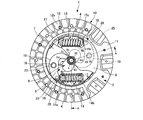
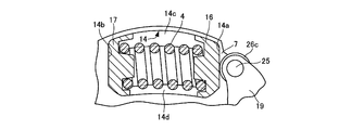
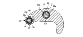
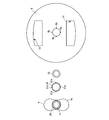
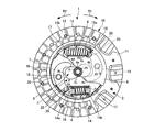
- FIG. 1 is a view showing an embodiment of a torsional vibration damping device according to the present invention, and is a cross-sectional view taken along the line AA in FIG. It is a figure which shows one Embodiment of the torsional vibration damping device which concerns on this invention, and is B direction arrow sectional drawing of FIG. It is a figure which shows one Embodiment of the torsional vibration damping device which concerns on this invention, and is C direction arrow sectional drawing of FIG.
- FIG. 6 is a diagram showing an embodiment of a torsional vibration damping device according to the present invention, and is a cross-sectional view in the DD direction of FIG. It is a figure which shows one Embodiment of the torsional vibration damping device which concerns on this invention, and is a figure explaining a cam member a component. It is a figure which shows one Embodiment of the torsional vibration damping device which concerns on this invention, and is a front view of a cam member.
- FIGS. 1 to 15 are diagrams showing an embodiment of a torsional vibration damping device according to the present invention.
- a torsional vibration damping device 1 is provided on the same axis as the first rotating member 2 to which rotational torque from an internal combustion engine (not shown) that is a drive source is input, and the first rotating member 2.
- the second rotating member 3 Provided between the first rotating member 2 and the second rotating member 3, the second rotating member 3 for transmitting the rotational torque of the first rotating member 2 to a transmission of a drive system (not shown),
- a pair of coil springs 4 are provided as elastic members that are compressed in the circumferential direction of the first rotating member 2 when the first rotating member 2 and the second rotating member 3 rotate relative to each other.
- the second rotating member 3 is provided on the outer periphery of the boss 5 and the boss 5 as a boss member as a second rotating member that is spline-fitted to the outer periphery of the input shaft 21 of the drive-line transmission. And a cam member 6.
- the boss 5 and the cam member 6 may be integrally formed. Further, the boss 5 and the cam member 6 are formed separately, spline portions are formed on the outer peripheral portion of the boss 5 and the inner peripheral portion of the cam member 6, and the boss 5 and the cam member 6 are spline-fitted. Also good.
- the first rotating member 2 includes a pair of disk plates 7 and 8 and a clutch disk 10.
- the disk plates 7 and 8 are disposed on both sides of the boss 5 in the axial direction, and are connected to each other by a pin 9 and a pin 18 as a swinging fulcrum at a predetermined interval in the axial direction.
- boss 5 is accommodated in the circular center holes 7 a and 8 a of the disc plates 7 and 8, and the boss 5 is provided on the same axis as the disc plates 7 and 8.
- the pins 9 and 18 are bridged to the disk plates 7 and 8, and both end portions in the axial direction are formed with large diameters, so that the pins 9 and 18 are locked to the disk plates 7 and 8. For this reason, the disk plates 7 and 8 are integrally rotated by being integrated by the pins 18 and 9.
- the clutch disk 10 is provided radially outward of the disk plate 7, and includes a cushioning plate 11 and friction materials 12a and 12b.
- the cushioning plate 11 is composed of a ring-shaped member that undulates in the thickness direction, and is fixed to the disk plates 7 and 8 by pins 9.
- the friction materials 12a and 12b are fixed to both surfaces of the cushioning plate 11 by rivets 13, and the friction materials 12a and 12b are bolted to a flywheel (not shown) fixed to a crankshaft of an internal combustion engine and a flywheel. Located between the pressure plates of the clutch cover.
- the disc plates 7 and 8 are respectively formed with a pair of receiving holes 14 and 15 that are spaced apart in the circumferential direction, and the receiving holes 14 and 15 are formed in the axial direction of the disc plates 7 and 8.
- the coil spring 4 is accommodated so as to face the surface.
- the receiving holes 14 and 15 are punched out by a press on the outer peripheral side of the coil spring 4, and both end portions in the circumferential direction of the disk plates 7 and 8 are closed ends.
- the disk plates 7 and 8 include outer support pieces (accommodating portions) 14c and 15c extending in the circumferential direction along the radially outer edges of the accommodating holes 14.
- Inner support pieces (accommodation holes) 14d and 15d extending in the circumferential direction along the radially inner edge of the accommodation hole 14 are provided.
- the outer support pieces 14c and 15c and the inner support pieces 14d and 15d are provided as follows.
- the disk plates 7 and 8 protrude outward in the axial direction.
- both ends in the circumferential direction of the coil spring 4 are held by spring sheets 16 and 17 which are holding members, and end windings are formed on the inner peripheral surfaces of the spring sheets 16 and 17.
- This end turn corresponds to one or two turns at both ends of the coil spring 4 in the circumferential direction, and both end portions in the circumferential direction of the coil spring 4 are seated on this end turn.
- the coil spring 4 can be prevented from rotating and can be attached to the spring seats 16 and 17 by engaging the start and end of the rotational direction with the end winding.
- the closed ends of the circumferential ends of the disk plates 7 and 8 are the contact portions 14a, 14b and 15a with which the circumferential ends of the spring seats 16 and 17 abut. 15b, and in a state where the spring seats 16 and 17 are extended, the circumferential ends of the spring seats 16 and 17 come into contact with the contact portions 14a, 14b, 15a and 15b.
- the outer peripheral portions of the spring seats 16 and 17 are opposed to the outer support pieces 14c and 15c and the inner support pieces 14d and 15d, and the spring sheets 16 and 17 are provided with the outer support pieces 14c and 15c and the inner support pieces 14d, 15d prevents the receiving holes 14 and 15 from coming out.
- An arm member 19 serving as a torque transmission member is provided between the spring seat 16 on one side in the circumferential direction and the cam member 6, and this arm member 19 is located between the disk plates 7 and 8 and is attached to the pin 18. It is swingably supported.
- a needle bearing 20 is interposed between the pin 18 and the arm member 19.
- the needle bearing 20 includes an outer race 20a attached to the arm member 19, and a needle needle 20b interposed between the outer race 20a and the pin 18, and the outer race 20a removes the needle needle 20b.
- the arm member 19 is rotatably attached to the pin 18 via the needle bearing 20.
- the other end of the arm member 19 is formed with bifurcated protruding pieces 19c and 19d, and the protruding pieces 19c and 19d are connected by a pin 25.
- the pin 25 is supported by the protruding pieces 19c and 19d.
- a roller member 26 as a rolling member is rotatably attached to the pin 25.
- the roller member 26 includes an outer race 26a provided on the outer peripheral portion of the pin 25, a needle bearing made up of a needle needle 26b interposed between the outer race 26a and the pin 25, and an outer race on the outer peripheral portion of the outer race 26a.
- the roller 26c is attached to the roller 26a.
- the roller 26c is rotatable with respect to the pin 25 via a needle bearing.
- the roller 26c comes into contact with the outer circumferential surface of the spring seat 16, and the other end of the arm member 19 comes into contact with the outer circumferential surface of the spring seat 16 through the roller 26c.
- the cam member 6 is formed in a peanut shape, and the cam surface of the cam member 6 has a peanut shape.
- the cam surface 6A of the cam member 6 includes an outer periphery 51a of a first circle 51 having a radius r1 centered on the rotation center axis O1 of the cam member 6, and an axis L direction from the rotation center axis O1.
- the radius r2 of the pair of second circles 52 has the same size.
- the curvatures of the cam surfaces 6c and 6d that are continuous from the cam surface 6a of the outer periphery 51a of the first circle 51 to the cam surface 6b of the outer periphery 52a of the second circle 52 are the cam surfaces of the outer periphery 52a of the second circle 52. It is smaller than the curvature of 6b.
- the cam surface 6a of the outer periphery 51a of the first circle 51 is a point on the outer periphery 51a of the first circle 51, whereas the cam of the outer periphery 52a of the second circle 52 is The surface 6b extends in the circumferential direction of the outer periphery 51a of the second circle 52 connecting the terminal ends of the cam surfaces 6c and 6d.
- the arm member 19 is arranged point-symmetrically with respect to the central axis of the disk plates 7, 8, that is, the rotational central axis O 1 of the cam member 6, and the cam surface sandwiches the rotational central axis O 1 of the cam member 6. 6A is in contact.
- the tip of the arm member 19 is in contact with the cam surface 6a. At this time, the rotation center axis O1 is sandwiched. The separation distance of the arm member 19 is the shortest.
- the cam member 6 rotates in this way, and the position of the cam surface 6A where one end of the arm member 19 abuts is varied, whereby the spring seat 16 is biased by the arm member 19 and the coil The amount of compression of the spring 4 is variable. At this time, the spring seat 16 moves along the periphery of the accommodation holes 14 and 15 so as to approach and separate from the spring seat 17.
- a hysteresis mechanism 27 is interposed between the disk plates 7 and 8 and the cam member 6, and the hysteresis mechanism 27 is an annular friction material 28, 29, 30, 31. And a disc spring 32.
- the friction materials 28 and 29 are made of a member having a predetermined friction coefficient on the surface, and are fixed to the outer circumferential surface of the cam member 6 in the axial direction by an adhesive.
- the friction members 28 and 29 are integrally provided with pins and the like, and the pins are fitted into pin holes formed on the outer circumferential surface of the cam member 6 in the axial direction, whereby the friction members 28 and 29 are attached to the cam member 6. It may be attached.
- the friction material 30 is composed of a member having a predetermined friction coefficient on the surface, and is fixed to the inner peripheral surface of the disk plate 7 with an adhesive.
- a pin or the like may be integrally provided on the friction material 30 and the pin may be attached to the disc plate 7 by fitting it into a pin hole formed on the inner peripheral surface of the disc plate 7.
- the friction material 31 is formed of a member having a predetermined friction coefficient on the surface, and a plurality of pins 31a are integrally provided on the radially outer peripheral surface.
- the pin 31 a is fitted into a pin hole 8 b formed on the inner peripheral surface of the disk plate 8, and the friction material 31 is attached to the inner peripheral surface of the disk plate 8.
- the disc spring 32 is formed in a conical shape, and is interposed between the friction material 31 and the disk plate 8.
- the disc spring 32 generates an elastic force in the axial direction of the cam member 6, thereby bringing the friction material 31 and the friction material 28 into frictional contact, and bringing the friction material 29 and the friction material 30 into friction contact.
- the cam member 6 and the disk plates 7 and 8 are brought into frictional contact with each other to generate hysteresis torque between the cam member 6 and the disk plates 7 and 8.
- the hysteresis mechanism may be configured such that the friction materials 28 and 29 are eliminated and the friction materials 30 and 31 are directly brought into frictional contact with the outer circumferential surface of the cam member 6 in the axial direction.
- 10 and 11 show a state in which the disk plates 7 and 8 are rotating in the counterclockwise rotation direction (R2 direction) from the state of FIG. 1 in response to the rotational torque of the internal combustion engine.
- R2 direction counterclockwise rotation direction
- the description will be made assuming that the disk plates 7 and 8 are twisted in the clockwise direction (R1 direction) on the positive side.
- the boss 5 is twisted to the positive side with respect to the disk plates 7 and 8 when the vehicle is accelerated.
- the friction materials 12 a and 12 b are pressed against the pressure plate and frictionally engaged with the flywheel and the pressure plate, whereby the rotational torque of the internal combustion engine is input to the disk plates 7 and 8.
- the relative rotation between the disk plates 7 and 8 and the boss 5 is small, that is, the torsion angle between the disk plates 7 and 8 and the boss 5 is small near 0 °.
- the cam member 6 is positioned at the initial position and rotates integrally with the boss 5.
- the arm member 19 uses the pin 18 as a fulcrum by the reaction force of the coil spring 4 and presses the cam member 6 according to the lever principle. Therefore, the rotational torque of the disk plates 7 and 8 is transmitted to the cam member 6 via the coil spring 4 and the arm member 19. For this reason, the rotational torque of the internal combustion engine is transmitted to the input shaft of the transmission, and at this time, the amount of compression of the coil spring 4 is small.
- the other end portion of the arm member 19 moves along the circumferential outer circumferential surface of the spring seat 16 via the roller 26c, so that the spring seat 16 can be prevented from moving in the circumferential direction.
- the spring seat 16 since one end in the circumferential direction of the spring seat 17 is in contact with the contact portions 14 b and 15 b, the spring seat 16 extends along the periphery of the accommodation holes 14 and 15. The coil spring 4 is compressed by moving to the spring seat 17 side.
- the arm member 19 biases the coil spring 4 in this way, so that the arm member 19 uses the pin 18 as a fulcrum by the reaction force of the coil spring 4 to be compressed, and the cam member 6 is pressed with a strong pressing force by the lever principle. Press.
- the one end portion of the arm member 19 when one end portion of the arm member 19 moves from the cam surface 6d to the cam surface 6b, the one end portion of the arm member 19 has a short distance in the short direction and the short direction from the cam surface 6d of the cam member 6 having a small curvature. Since the distance is abutted against the cam surface 6b having a long curvature, the amount of compression of the coil spring 4 with respect to the torsion angles of the disk plates 7 and 8 and the boss 5 increases, and the rigidity of the coil spring 19 increases.
- the arm member 19 uses the pin 18 as a fulcrum by the reaction force of the coil spring 4 compressed by the arm member 19 and the cam member 6, and presses the cam member 6 with a strong pressing force according to the lever principle.
- the coil spring 4 is made to have low rigidity and the power of the drive system is transmitted from the boss 5 to the disk plates 7 and 8 while the disk plates 7 and 8 are transmitted. And torsional vibration of the boss 5 can be absorbed and damped.
- the other end portion of the arm member 19 moves along the circumferential outer peripheral surface of the spring seat 16 via the roller 26c so as not to prevent the spring seat 16 from moving in the circumferential direction. Can be.
- the cam member 6 can function as a torque limiter during acceleration of the vehicle.
- the arm member 19 Since the curvature of the cam surface 6c is larger than the curvature of the cam surface 6b, the arm member 19 is counterclockwise via the pin 18 when one end of the arm member 19 moves from the cam surface 6d to the cam surface 6b. It rotates greatly in the direction of rotation.
- the one end portion of the arm member 19 when one end portion of the arm member 19 moves from the cam surface 6c to the cam surface 6b, the one end portion of the arm member 19 has a short distance in the short direction and the short direction from the cam surface 6c of the cam member 6 having a small curvature. Since the distance is abutted against the cam surface 6b having a long curvature, the amount of compression of the coil spring 4 with respect to the torsion angles of the disk plates 7 and 8 and the boss 5 increases, and the rigidity of the coil spring 19 increases.
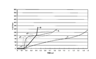
- the torsional characteristics of the torsional vibration damping device 1 during acceleration will be described with reference to FIG. Note that the torsional characteristics at the time of deceleration are the same as those at the time of acceleration, and thus description thereof is omitted.
- one end of the arm member 19 moves along the cam surface 6d having a smaller curvature than the cam surface 6b. As indicated by the region a1, the rigidity of the coil spring 4 is low.
- the torsion angle between the disk plates 7 and 8 and the boss 5 is further increased and one end portion of the arm member 19 moves from the cam surface 6d to the cam surface 6b, the one end portion of the arm member 19 is a distance in the short direction. Is short and the cam surface 6d of the cam member 6 having a small curvature is in contact with the cam surface 6b having a long short distance and a large curvature. Therefore, the compression amount of the coil spring 4 with respect to the torsion angles of the disc plates 7 and 8 and the boss 5 And the rigidity of the coil spring 19 increases as shown in the region a2.
- the cam surface 6b 2 is formed in the same circular shape as the outer periphery 52a of the circle 52, the compression amount of the coil spring 4 with respect to the torsion angles of the disk plates 7 and 8 and the boss 5 gradually increases, as shown by a region a3.
- the coil spring 4 has low rigidity.
- the torsional vibration damping device disclosed in Patent Document 2 can widen the torsion angle of the disk plate (first rotating member) and the boss (second rotating member), but the curvature of the contacted surface is constant. For this reason, when the boss is twisted with respect to the disk plate, the torsion characteristic is such that the amount of bending (rigidity) of the coil spring gradually increases.
- FIG. 14 is a characteristic diagram showing the relationship between the rotational speed of the internal combustion engine and the torque fluctuation of the internal combustion engine.
- the torque increases in a steady rotational region where the rotational speed of the internal combustion engine is 1500 rpm or more and is driven near 2000 rpm. Assume that torsional resonance of the system occurs.
- the torsional characteristics of the torsional vibration damping device 1 it is preferable to set the torsional characteristics of the torsional vibration damping device 1 so that the torsional rigidity of the torsional vibration damping device 1 (the rigidity of the coil spring 4) is reduced around 2000 rpm.
- the shape of the cam member 6 is formed in a peanut shape, and the first end of the cam member 6 is moved so that one end of the arm member 19 is moved along the cam surface 6b of the cam member 6 in the rotation region of 2000 rpm.
- the rigidity of the coil spring 4 can be made low (region a3 in FIG. 13), and due to torque fluctuations of the drive source Reduces torsional vibration caused by rotational fluctuations, and torsional resonance in the drive system to reduce the noise caused by the collision of the idle gear pair of the transmission gear set and the torsional resonance caused by the torsional resonance of the drive system be able to.
- one end of the arm member 19 is moved along the cam surface 6d having a smaller curvature than the cam surface 6b.
- the rigidity of the coil spring 4 can be reduced, and the torsional vibration caused by the rotational fluctuation caused by the torque fluctuation of the drive source can be attenuated, and the transmission gear pair in the unloaded state can be attenuated. Generation of a rattling sound can be suppressed.
- a large torsional vibration such as a jarr sound or a booming noise does not occur in an area between an idle region where a rattling sound is generated and a region where a jallah sound or a booming sound is generated. Therefore, the coil spring 4 does not need to have low rigidity.
- the cam member 6 is formed in a peanut shape, and one end portion of the arm member 19 is brought into contact with the cam surface 6b from the cam surface 6d of the cam member 6, so 5 is provided to increase the rigidity of the coil spring 4 by rapidly increasing the amount of bending of the coil spring 4 with respect to the amount of change in the torsion angle 5.
- the cam surface 6A of the cam member 6 is aligned with the outer circumference 51a of the first circle 51 having the radius r1 centered on the rotation center axis O1 of the cam member 6 and the rotation center axis O1.
- the curvature of the cam surfaces 6c and 6d formed in a curved surface and continuing from the cam surface 6a of the outer periphery 51a of the first circle 51 to the cam surface 6b of the outer periphery 52a of the second circle 52 is the outer periphery 52a of the second circle 52.
- the torsional angle between the disk plates 7 and 8 and the boss 5 can be increased to about half that of the torsional vibration damping device disclosed in Patent Document 2, and the coil spring 4 is downsized.
- the torsional vibration can be efficiently damped in the necessary regions (the region where the rattling sound is generated and the region where the jagged sound and the booming sound are generated).
- the cam member 6 can be functioned as a torque limiter.
- the roller 26c is rotatably provided at the other end of the arm member 19, and the other end of the arm member 19 is in contact with the spring seat 16 via the roller 26c.
- the coil spring 4 can be elastically deformed in the circumferential direction of the disk plates 7 and 8 while the other end of 19 is smoothly slid along the circumferential outer peripheral surface of the spring seat 16 via the roller member 26. it can.
- twist angles of the disk plates 7 and 8 and the boss 5 are simply configured by simply providing the coil spring 4, the arm member 19 and the cam member 6 between the disk plates 7 and 8 and the boss 5. Can be widened, and the configuration of the torsional vibration damping device 1 can be simplified.
- the arm member 19 is arranged point-symmetrically with respect to the central axis of the disk plates 7 and 8, so the arm member 19 sandwiches the central axis of the disk plates 7 and 8 and the cam member 6. Can be pinched.
- the torsional characteristics and the torsional angle when the disk plates 7 and 8 and the boss 5 rotate relative to each other depend on the shape of the cam surface 6A of the cam member 6 (the radii r1 and r2 of the circles 51 and 52, the circle 51, (Separation distance of rotation center axes O1 and O2 of 52, etc.)
- the shape of the arm member 19, etc. it is possible to set an arbitrary twist characteristic and twist angle.
- the torsional vibration damping device 1 is interposed between the internal combustion engine of the vehicle and the drive system having the transmission.
- the present invention is not limited to this, and is provided in the drive system of the vehicle or the like. Any torsional vibration damping device can be used.
- the present invention is applied to a torsional vibration damping device such as a hybrid damper interposed between an output shaft of an internal combustion engine and a power split mechanism that splits power into an electric motor and a wheel side output shaft. May be.
- the present invention may be applied to a torsional vibration damping device such as a lockup damper interposed between a lockup clutch device of a torque converter and a transmission gear set. Further, a torsional vibration damping device may be provided between the differential case and a ring gear provided on the outer periphery of the differential case.
- a torsional vibration damping device such as a lockup damper interposed between a lockup clutch device of a torque converter and a transmission gear set.
- a torsional vibration damping device may be provided between the differential case and a ring gear provided on the outer periphery of the differential case.
- the torsional vibration damping device can reduce the size of the elastic member, reduce the installation space and attenuate the torsional vibration in a necessary region, and increase the size of the entire device.
- the rotation torque is transmitted between the first rotation member and the second rotation member.
- the rotation torque is transmitted between the internal combustion engine of the vehicle and the drive system.
- it is useful as a torsional vibration damping device or the like in which the first rotating member and the second rotating member are connected to each other via an elastic member so as to be relatively rotatable.
Landscapes
- Engineering & Computer Science (AREA)
- General Engineering & Computer Science (AREA)
- Mechanical Engineering (AREA)
- Physics & Mathematics (AREA)
- Acoustics & Sound (AREA)
- Aviation & Aerospace Engineering (AREA)
- Mechanical Operated Clutches (AREA)
Priority Applications (4)
| Application Number | Priority Date | Filing Date | Title |
|---|---|---|---|
| EP10861196.3A EP2657567B1 (de) | 2010-12-22 | 2010-12-22 | Torsionsschwingungs-dämpfungsvorrichtung |
| CN201080070814.2A CN103261731B (zh) | 2010-12-22 | 2010-12-22 | 扭转振动衰减装置 |
| PCT/JP2010/007416 WO2012085966A1 (ja) | 2010-12-22 | 2010-12-22 | 捩り振動減衰装置 |
| JP2012549477A JP5565473B2 (ja) | 2010-12-22 | 2010-12-22 | 捩り振動減衰装置 |
Applications Claiming Priority (1)
| Application Number | Priority Date | Filing Date | Title |
|---|---|---|---|
| PCT/JP2010/007416 WO2012085966A1 (ja) | 2010-12-22 | 2010-12-22 | 捩り振動減衰装置 |
Publications (1)
| Publication Number | Publication Date |
|---|---|
| WO2012085966A1 true WO2012085966A1 (ja) | 2012-06-28 |
Family
ID=46313273
Family Applications (1)
| Application Number | Title | Priority Date | Filing Date |
|---|---|---|---|
| PCT/JP2010/007416 Ceased WO2012085966A1 (ja) | 2010-12-22 | 2010-12-22 | 捩り振動減衰装置 |
Country Status (4)
| Country | Link |
|---|---|
| EP (1) | EP2657567B1 (de) |
| JP (1) | JP5565473B2 (de) |
| CN (1) | CN103261731B (de) |
| WO (1) | WO2012085966A1 (de) |
Cited By (1)
| Publication number | Priority date | Publication date | Assignee | Title |
|---|---|---|---|---|
| JP2020516829A (ja) * | 2017-05-23 | 2020-06-11 | シェフラー テクノロジーズ アー・ゲー ウント コー. カー・ゲーSchaeffler Technologies AG & Co. KG | トルクリミッタを備えるトーショナルバイブレーションダンパ |
Families Citing this family (6)
| Publication number | Priority date | Publication date | Assignee | Title |
|---|---|---|---|---|
| JP6769655B2 (ja) * | 2016-09-29 | 2020-10-14 | アイシン・エィ・ダブリュ株式会社 | 振動減衰装置およびその設計方法 |
| JP6384573B1 (ja) * | 2017-03-08 | 2018-09-05 | トヨタ自動車株式会社 | 捩り振動低減装置 |
| JP7355606B2 (ja) * | 2019-10-31 | 2023-10-03 | 株式会社エクセディ | トーションダンパ、及びダンパ装置 |
| JP7369060B2 (ja) * | 2020-02-26 | 2023-10-25 | 三菱重工エンジン&ターボチャージャ株式会社 | 軸継手装置及びねじり固有振動数調整方法 |
| CN114526312A (zh) * | 2020-11-23 | 2022-05-24 | 舍弗勒技术股份两合公司 | 具有离合器的减振装置 |
| CN114542663A (zh) * | 2020-11-24 | 2022-05-27 | 舍弗勒技术股份两合公司 | 扭矩传递装置及混合动力系统 |
Citations (5)
| Publication number | Priority date | Publication date | Assignee | Title |
|---|---|---|---|---|
| JPS57173620A (en) * | 1981-04-20 | 1982-10-26 | Daikin Mfg Co Ltd | Clutch disc |
| JPH0458642U (de) * | 1990-09-28 | 1992-05-20 | ||
| JP2001074102A (ja) | 1999-06-29 | 2001-03-23 | Aisin Seiki Co Ltd | トルク変動吸収装置 |
| JP2003194095A (ja) | 2001-10-17 | 2003-07-09 | Aisin Seiki Co Ltd | トルク変動吸収装置 |
| JP2008304008A (ja) * | 2007-06-08 | 2008-12-18 | Aisin Seiki Co Ltd | トルク変動吸収装置 |
Family Cites Families (5)
| Publication number | Priority date | Publication date | Assignee | Title |
|---|---|---|---|---|
| FR2718815B1 (fr) * | 1994-04-14 | 1996-05-31 | Valeo | Volant amortisseur, notamment pour véhicule automobile. |
| US7252060B2 (en) * | 2005-07-14 | 2007-08-07 | Borgwarner Inc | Torsional damper for balance shafts |
| WO2009026872A1 (de) * | 2007-08-27 | 2009-03-05 | Luk Lamellen Und Kupplungsbau Beteiligungs Kg | Vorrichtung zum ausgleich von drehmomentschwankungen einer welle |
| DE112009001958A5 (de) * | 2008-09-01 | 2011-05-26 | Schaeffler Technologies Gmbh & Co. Kg | Zweimassenschwungrad |
| DE102009007373A1 (de) * | 2009-02-04 | 2010-08-05 | Magna Powertrain Ag & Co Kg | Zweimassenschwungrad |
-
2010
- 2010-12-22 JP JP2012549477A patent/JP5565473B2/ja not_active Expired - Fee Related
- 2010-12-22 EP EP10861196.3A patent/EP2657567B1/de not_active Not-in-force
- 2010-12-22 CN CN201080070814.2A patent/CN103261731B/zh not_active Expired - Fee Related
- 2010-12-22 WO PCT/JP2010/007416 patent/WO2012085966A1/ja not_active Ceased
Patent Citations (5)
| Publication number | Priority date | Publication date | Assignee | Title |
|---|---|---|---|---|
| JPS57173620A (en) * | 1981-04-20 | 1982-10-26 | Daikin Mfg Co Ltd | Clutch disc |
| JPH0458642U (de) * | 1990-09-28 | 1992-05-20 | ||
| JP2001074102A (ja) | 1999-06-29 | 2001-03-23 | Aisin Seiki Co Ltd | トルク変動吸収装置 |
| JP2003194095A (ja) | 2001-10-17 | 2003-07-09 | Aisin Seiki Co Ltd | トルク変動吸収装置 |
| JP2008304008A (ja) * | 2007-06-08 | 2008-12-18 | Aisin Seiki Co Ltd | トルク変動吸収装置 |
Non-Patent Citations (1)
| Title |
|---|
| See also references of EP2657567A4 * |
Cited By (2)
| Publication number | Priority date | Publication date | Assignee | Title |
|---|---|---|---|---|
| JP2020516829A (ja) * | 2017-05-23 | 2020-06-11 | シェフラー テクノロジーズ アー・ゲー ウント コー. カー・ゲーSchaeffler Technologies AG & Co. KG | トルクリミッタを備えるトーショナルバイブレーションダンパ |
| US11015677B2 (en) | 2017-05-23 | 2021-05-25 | Schaeffler Technologies AG & Co. KG | Torsional vibration damper with torque limiter |
Also Published As
| Publication number | Publication date |
|---|---|
| JP5565473B2 (ja) | 2014-08-06 |
| CN103261731B (zh) | 2015-07-29 |
| EP2657567A8 (de) | 2013-12-11 |
| EP2657567A1 (de) | 2013-10-30 |
| CN103261731A (zh) | 2013-08-21 |
| EP2657567A4 (de) | 2015-03-25 |
| EP2657567B1 (de) | 2017-06-28 |
| JPWO2012085966A1 (ja) | 2014-05-22 |
Similar Documents
| Publication | Publication Date | Title |
|---|---|---|
| JP5223999B2 (ja) | 捩り振動減衰装置 | |
| JP5633577B2 (ja) | 捩り振動減衰装置 | |
| JP5533883B2 (ja) | トルク変動吸収装置 | |
| JP5472490B2 (ja) | 捩り振動減衰装置 | |
| JP5527428B2 (ja) | 捩り振動減衰装置 | |
| JP5565473B2 (ja) | 捩り振動減衰装置 | |
| JP5772983B2 (ja) | 捩り振動減衰装置 | |
| JP5817918B2 (ja) | 捩り振動減衰装置 | |
| JP5299520B2 (ja) | 捩れ緩衝装置 | |
| JP2012237429A (ja) | 捩り振動減衰装置 | |
| JP2013174294A (ja) | 捩り振動減衰装置 | |
| JP2013164090A (ja) | 捩り振動減衰装置 | |
| JP2013190092A (ja) | 捩り振動減衰装置 | |
| JP2013108570A (ja) | 捩り振動減衰装置 | |
| JP2012215265A (ja) | 捩り振動減衰装置 | |
| JP2012246958A (ja) | 捩り振動減衰装置 | |
| JP2011241918A (ja) | 捩り振動減衰装置 | |
| JP2011241919A (ja) | 捩り振動減衰装置 |
Legal Events
| Date | Code | Title | Description |
|---|---|---|---|
| 121 | Ep: the epo has been informed by wipo that ep was designated in this application |
Ref document number: 10861196 Country of ref document: EP Kind code of ref document: A1 |
|
| ENP | Entry into the national phase |
Ref document number: 2012549477 Country of ref document: JP Kind code of ref document: A |
|
| REEP | Request for entry into the european phase |
Ref document number: 2010861196 Country of ref document: EP |
|
| NENP | Non-entry into the national phase |
Ref country code: DE |