WO2012086022A1 - 車両および車両の制御方法 - Google Patents
車両および車両の制御方法 Download PDFInfo
- Publication number
- WO2012086022A1 WO2012086022A1 PCT/JP2010/073085 JP2010073085W WO2012086022A1 WO 2012086022 A1 WO2012086022 A1 WO 2012086022A1 JP 2010073085 W JP2010073085 W JP 2010073085W WO 2012086022 A1 WO2012086022 A1 WO 2012086022A1
- Authority
- WO
- WIPO (PCT)
- Prior art keywords
- internal combustion
- combustion engine
- torque
- engine
- state
- Prior art date
- Legal status (The legal status is an assumption and is not a legal conclusion. Google has not performed a legal analysis and makes no representation as to the accuracy of the status listed.)
- Ceased
Links
Images




Classifications
-
- B—PERFORMING OPERATIONS; TRANSPORTING
- B60—VEHICLES IN GENERAL
- B60W—CONJOINT CONTROL OF VEHICLE SUB-UNITS OF DIFFERENT TYPE OR DIFFERENT FUNCTION; CONTROL SYSTEMS SPECIALLY ADAPTED FOR HYBRID VEHICLES; ROAD VEHICLE DRIVE CONTROL SYSTEMS FOR PURPOSES NOT RELATED TO THE CONTROL OF A PARTICULAR SUB-UNIT
- B60W20/00—Control systems specially adapted for hybrid vehicles
- B60W20/10—Controlling the power contribution of each of the prime movers to meet required power demand
- B60W20/15—Control strategies specially adapted for achieving a particular effect
- B60W20/17—Control strategies specially adapted for achieving a particular effect for noise reduction
-
- B—PERFORMING OPERATIONS; TRANSPORTING
- B60—VEHICLES IN GENERAL
- B60K—ARRANGEMENT OR MOUNTING OF PROPULSION UNITS OR OF TRANSMISSIONS IN VEHICLES; ARRANGEMENT OR MOUNTING OF PLURAL DIVERSE PRIME-MOVERS IN VEHICLES; AUXILIARY DRIVES FOR VEHICLES; INSTRUMENTATION OR DASHBOARDS FOR VEHICLES; ARRANGEMENTS IN CONNECTION WITH COOLING, AIR INTAKE, GAS EXHAUST OR FUEL SUPPLY OF PROPULSION UNITS IN VEHICLES
- B60K6/00—Arrangement or mounting of plural diverse prime-movers for mutual or common propulsion, e.g. hybrid propulsion systems comprising electric motors and internal combustion engines
- B60K6/20—Arrangement or mounting of plural diverse prime-movers for mutual or common propulsion, e.g. hybrid propulsion systems comprising electric motors and internal combustion engines the prime-movers consisting of electric motors and internal combustion engines, e.g. HEVs
- B60K6/22—Arrangement or mounting of plural diverse prime-movers for mutual or common propulsion, e.g. hybrid propulsion systems comprising electric motors and internal combustion engines the prime-movers consisting of electric motors and internal combustion engines, e.g. HEVs characterised by apparatus, components or means specially adapted for HEVs
- B60K6/36—Arrangement or mounting of plural diverse prime-movers for mutual or common propulsion, e.g. hybrid propulsion systems comprising electric motors and internal combustion engines the prime-movers consisting of electric motors and internal combustion engines, e.g. HEVs characterised by apparatus, components or means specially adapted for HEVs characterised by the transmission gearings
- B60K6/365—Arrangement or mounting of plural diverse prime-movers for mutual or common propulsion, e.g. hybrid propulsion systems comprising electric motors and internal combustion engines the prime-movers consisting of electric motors and internal combustion engines, e.g. HEVs characterised by apparatus, components or means specially adapted for HEVs characterised by the transmission gearings with the gears having orbital motion
-
- B—PERFORMING OPERATIONS; TRANSPORTING
- B60—VEHICLES IN GENERAL
- B60K—ARRANGEMENT OR MOUNTING OF PROPULSION UNITS OR OF TRANSMISSIONS IN VEHICLES; ARRANGEMENT OR MOUNTING OF PLURAL DIVERSE PRIME-MOVERS IN VEHICLES; AUXILIARY DRIVES FOR VEHICLES; INSTRUMENTATION OR DASHBOARDS FOR VEHICLES; ARRANGEMENTS IN CONNECTION WITH COOLING, AIR INTAKE, GAS EXHAUST OR FUEL SUPPLY OF PROPULSION UNITS IN VEHICLES
- B60K6/00—Arrangement or mounting of plural diverse prime-movers for mutual or common propulsion, e.g. hybrid propulsion systems comprising electric motors and internal combustion engines
- B60K6/20—Arrangement or mounting of plural diverse prime-movers for mutual or common propulsion, e.g. hybrid propulsion systems comprising electric motors and internal combustion engines the prime-movers consisting of electric motors and internal combustion engines, e.g. HEVs
- B60K6/42—Arrangement or mounting of plural diverse prime-movers for mutual or common propulsion, e.g. hybrid propulsion systems comprising electric motors and internal combustion engines the prime-movers consisting of electric motors and internal combustion engines, e.g. HEVs characterised by the architecture of the hybrid electric vehicle
- B60K6/44—Series-parallel type
- B60K6/445—Differential gearing distribution type
-
- B—PERFORMING OPERATIONS; TRANSPORTING
- B60—VEHICLES IN GENERAL
- B60W—CONJOINT CONTROL OF VEHICLE SUB-UNITS OF DIFFERENT TYPE OR DIFFERENT FUNCTION; CONTROL SYSTEMS SPECIALLY ADAPTED FOR HYBRID VEHICLES; ROAD VEHICLE DRIVE CONTROL SYSTEMS FOR PURPOSES NOT RELATED TO THE CONTROL OF A PARTICULAR SUB-UNIT
- B60W10/00—Conjoint control of vehicle sub-units of different type or different function
- B60W10/04—Conjoint control of vehicle sub-units of different type or different function including control of propulsion units
- B60W10/06—Conjoint control of vehicle sub-units of different type or different function including control of propulsion units including control of combustion engines
-
- B—PERFORMING OPERATIONS; TRANSPORTING
- B60—VEHICLES IN GENERAL
- B60W—CONJOINT CONTROL OF VEHICLE SUB-UNITS OF DIFFERENT TYPE OR DIFFERENT FUNCTION; CONTROL SYSTEMS SPECIALLY ADAPTED FOR HYBRID VEHICLES; ROAD VEHICLE DRIVE CONTROL SYSTEMS FOR PURPOSES NOT RELATED TO THE CONTROL OF A PARTICULAR SUB-UNIT
- B60W10/00—Conjoint control of vehicle sub-units of different type or different function
- B60W10/04—Conjoint control of vehicle sub-units of different type or different function including control of propulsion units
- B60W10/08—Conjoint control of vehicle sub-units of different type or different function including control of propulsion units including control of electric propulsion units, e.g. motors or generators
-
- B—PERFORMING OPERATIONS; TRANSPORTING
- B60—VEHICLES IN GENERAL
- B60W—CONJOINT CONTROL OF VEHICLE SUB-UNITS OF DIFFERENT TYPE OR DIFFERENT FUNCTION; CONTROL SYSTEMS SPECIALLY ADAPTED FOR HYBRID VEHICLES; ROAD VEHICLE DRIVE CONTROL SYSTEMS FOR PURPOSES NOT RELATED TO THE CONTROL OF A PARTICULAR SUB-UNIT
- B60W20/00—Control systems specially adapted for hybrid vehicles
-
- B—PERFORMING OPERATIONS; TRANSPORTING
- B60—VEHICLES IN GENERAL
- B60W—CONJOINT CONTROL OF VEHICLE SUB-UNITS OF DIFFERENT TYPE OR DIFFERENT FUNCTION; CONTROL SYSTEMS SPECIALLY ADAPTED FOR HYBRID VEHICLES; ROAD VEHICLE DRIVE CONTROL SYSTEMS FOR PURPOSES NOT RELATED TO THE CONTROL OF A PARTICULAR SUB-UNIT
- B60W30/00—Purposes of road vehicle drive control systems not related to the control of a particular sub-unit, e.g. of systems using conjoint control of vehicle sub-units
- B60W30/18—Propelling the vehicle
- B60W30/18009—Propelling the vehicle related to particular drive situations
- B60W30/18054—Propelling the vehicle related to particular drive situations at stand still, e.g. engine in idling state
-
- B—PERFORMING OPERATIONS; TRANSPORTING
- B60—VEHICLES IN GENERAL
- B60W—CONJOINT CONTROL OF VEHICLE SUB-UNITS OF DIFFERENT TYPE OR DIFFERENT FUNCTION; CONTROL SYSTEMS SPECIALLY ADAPTED FOR HYBRID VEHICLES; ROAD VEHICLE DRIVE CONTROL SYSTEMS FOR PURPOSES NOT RELATED TO THE CONTROL OF A PARTICULAR SUB-UNIT
- B60W30/00—Purposes of road vehicle drive control systems not related to the control of a particular sub-unit, e.g. of systems using conjoint control of vehicle sub-units
- B60W30/18—Propelling the vehicle
- B60W30/20—Reducing vibrations in the driveline
-
- B—PERFORMING OPERATIONS; TRANSPORTING
- B60—VEHICLES IN GENERAL
- B60W—CONJOINT CONTROL OF VEHICLE SUB-UNITS OF DIFFERENT TYPE OR DIFFERENT FUNCTION; CONTROL SYSTEMS SPECIALLY ADAPTED FOR HYBRID VEHICLES; ROAD VEHICLE DRIVE CONTROL SYSTEMS FOR PURPOSES NOT RELATED TO THE CONTROL OF A PARTICULAR SUB-UNIT
- B60W2510/00—Input parameters relating to a particular sub-units
- B60W2510/06—Combustion engines, Gas turbines
- B60W2510/0638—Engine speed
- B60W2510/0642—Idle condition
-
- B—PERFORMING OPERATIONS; TRANSPORTING
- B60—VEHICLES IN GENERAL
- B60W—CONJOINT CONTROL OF VEHICLE SUB-UNITS OF DIFFERENT TYPE OR DIFFERENT FUNCTION; CONTROL SYSTEMS SPECIALLY ADAPTED FOR HYBRID VEHICLES; ROAD VEHICLE DRIVE CONTROL SYSTEMS FOR PURPOSES NOT RELATED TO THE CONTROL OF A PARTICULAR SUB-UNIT
- B60W2520/00—Input parameters relating to overall vehicle dynamics
- B60W2520/04—Vehicle stop
-
- B—PERFORMING OPERATIONS; TRANSPORTING
- B60—VEHICLES IN GENERAL
- B60W—CONJOINT CONTROL OF VEHICLE SUB-UNITS OF DIFFERENT TYPE OR DIFFERENT FUNCTION; CONTROL SYSTEMS SPECIALLY ADAPTED FOR HYBRID VEHICLES; ROAD VEHICLE DRIVE CONTROL SYSTEMS FOR PURPOSES NOT RELATED TO THE CONTROL OF A PARTICULAR SUB-UNIT
- B60W2556/00—Input parameters relating to data
-
- B—PERFORMING OPERATIONS; TRANSPORTING
- B60—VEHICLES IN GENERAL
- B60W—CONJOINT CONTROL OF VEHICLE SUB-UNITS OF DIFFERENT TYPE OR DIFFERENT FUNCTION; CONTROL SYSTEMS SPECIALLY ADAPTED FOR HYBRID VEHICLES; ROAD VEHICLE DRIVE CONTROL SYSTEMS FOR PURPOSES NOT RELATED TO THE CONTROL OF A PARTICULAR SUB-UNIT
- B60W30/00—Purposes of road vehicle drive control systems not related to the control of a particular sub-unit, e.g. of systems using conjoint control of vehicle sub-units
- B60W30/18—Propelling the vehicle
- B60W30/18009—Propelling the vehicle related to particular drive situations
- B60W30/18018—Start-stop drive, e.g. in a traffic jam
-
- Y—GENERAL TAGGING OF NEW TECHNOLOGICAL DEVELOPMENTS; GENERAL TAGGING OF CROSS-SECTIONAL TECHNOLOGIES SPANNING OVER SEVERAL SECTIONS OF THE IPC; TECHNICAL SUBJECTS COVERED BY FORMER USPC CROSS-REFERENCE ART COLLECTIONS [XRACs] AND DIGESTS
- Y02—TECHNOLOGIES OR APPLICATIONS FOR MITIGATION OR ADAPTATION AGAINST CLIMATE CHANGE
- Y02T—CLIMATE CHANGE MITIGATION TECHNOLOGIES RELATED TO TRANSPORTATION
- Y02T10/00—Road transport of goods or passengers
- Y02T10/60—Other road transportation technologies with climate change mitigation effect
- Y02T10/62—Hybrid vehicles
-
- Y—GENERAL TAGGING OF NEW TECHNOLOGICAL DEVELOPMENTS; GENERAL TAGGING OF CROSS-SECTIONAL TECHNOLOGIES SPANNING OVER SEVERAL SECTIONS OF THE IPC; TECHNICAL SUBJECTS COVERED BY FORMER USPC CROSS-REFERENCE ART COLLECTIONS [XRACs] AND DIGESTS
- Y02—TECHNOLOGIES OR APPLICATIONS FOR MITIGATION OR ADAPTATION AGAINST CLIMATE CHANGE
- Y02T—CLIMATE CHANGE MITIGATION TECHNOLOGIES RELATED TO TRANSPORTATION
- Y02T10/00—Road transport of goods or passengers
- Y02T10/60—Other road transportation technologies with climate change mitigation effect
- Y02T10/72—Electric energy management in electromobility
-
- Y—GENERAL TAGGING OF NEW TECHNOLOGICAL DEVELOPMENTS; GENERAL TAGGING OF CROSS-SECTIONAL TECHNOLOGIES SPANNING OVER SEVERAL SECTIONS OF THE IPC; TECHNICAL SUBJECTS COVERED BY FORMER USPC CROSS-REFERENCE ART COLLECTIONS [XRACs] AND DIGESTS
- Y10—TECHNICAL SUBJECTS COVERED BY FORMER USPC
- Y10S—TECHNICAL SUBJECTS COVERED BY FORMER USPC CROSS-REFERENCE ART COLLECTIONS [XRACs] AND DIGESTS
- Y10S903/00—Hybrid electric vehicles, HEVS
- Y10S903/902—Prime movers comprising electrical and internal combustion motors
- Y10S903/903—Prime movers comprising electrical and internal combustion motors having energy storing means, e.g. battery, capacitor
- Y10S903/93—Conjoint control of different elements
Definitions
- the present invention relates to a vehicle and vehicle control.
- Patent Document 1 describes a gear mechanism included in a drive device due to fluctuations in engine torque by generating torque from an electric motor in a hybrid vehicle including an engine and an electric motor.
- a technique for suppressing generated abnormal noise is disclosed.
- the present invention has been made to solve the above-described problems, and an object of the present invention is to provide a vehicle that includes an internal combustion engine and an electric motor coupled to the internal combustion engine via a gear mechanism. This is to achieve a good balance between noise suppression and stabilization of the operating state of the internal combustion engine.
- a vehicle includes an internal combustion engine, an electric motor coupled to the internal combustion engine via a gear mechanism, and a control device that controls the electric motor.
- the control device When the internal combustion engine is in an idle state and the combustion state of the internal combustion engine is good, the control device generates torque in a direction that hinders the operation of the internal combustion engine from the electric motor.
- the control device when the internal combustion engine is in an idling state and the combustion state is good, causes the torque in a direction that hinders the operation of the internal combustion engine to be larger than in the case where the combustion state is not good. .
- the control device does not generate torque from the electric motor in a direction that hinders the operation of the internal combustion engine.
- the control device determines whether or not the combustion state is good based on the state of the internal combustion engine during operation of the internal combustion engine, and stores the determination result.
- the control device When the internal combustion engine is in an idle state with the vehicle stopped, the control device generates a torque in a direction that hinders the operation of the internal combustion engine from the electric motor when there is no history that the combustion state is determined to be good.
- torque in a direction that hinders the operation of the internal combustion engine is not generated from the electric motor.
- control device determines that the combustion state is not good and stores the determination result when the rotation speed of the internal combustion engine does not reach the predetermined speed after the internal combustion engine is started until the predetermined time elapses. .
- the control device determines that the combustion state is not good when the rotational speed of the internal combustion engine falls below a predetermined speed while the internal combustion engine is in an idle state while the motor is not generating torque.
- the determination result is stored.
- the control device determines that the combustion state is not good when the torque of the internal combustion engine falls below a predetermined torque while in a load operation state in which a larger torque is output than when the internal combustion engine is in an idle state. And memorize the judgment result.
- a vehicle includes an internal combustion engine, an electric motor coupled to the internal combustion engine via a gear mechanism, and a control device that controls the electric motor.
- the control device When the internal combustion engine is in an idle state and the standard fuel having better volatility than the heavy fuel is used, the control device generates a torque in a direction that hinders the operation of the internal combustion engine from the electric motor.
- control device operates the internal combustion engine when the standard fuel is used when the internal combustion engine is in an idle state, compared to when a heavy fuel that is less volatile than the standard fuel is used. Increase the torque in the direction of obstruction.
- control device does not generate torque from the electric motor in a direction that hinders the operation of the internal combustion engine when heavy fuel is used when the internal combustion engine is in an idle state.
- the suppression of abnormal noise generated by the gear mechanism and the stabilization of the operating state of the internal combustion engine are achieved in a well-balanced manner. be able to.
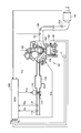
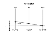
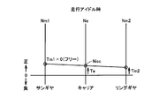
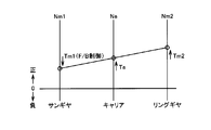
- FIG. 1 is an overall block diagram of a vehicle. It is a figure which shows the detail of an engine. The alignment chart at the time of engine starting is shown. The nomograph at the time of a stop idling is shown. The alignment chart at the time of driving
- FIG. 1 is an overall block diagram of a vehicle 1 according to an embodiment of the present invention.
- this vehicle 1 includes an engine 100, a first MG (Motor Generator) 20, a second MG 30, a power split device 40, a speed reducer 50, a PCU (Power Control Unit) 60, a battery. 70, a drive wheel 80, and an ECU (Electronic Control Unit) 200.
- MG Motor Generator
- PCU Power Control Unit
- 70 Battery
- drive wheel 80 and an ECU (Electronic Control Unit) 200.
- Engine 100, first MG 20 and second MG 30 are connected via power split device 40.
- the vehicle 1 travels with driving force output from at least one of the engine 100 and the second MG 30.
- the power generated by the engine 100 is divided into two paths by the power split device 40. That is, one is a path that is transmitted to the drive wheels 80 via the speed reducer 50, and the other is a path that is transmitted to the first MG 20.
- the engine 100 is an internal combustion engine controlled by a control signal S1 (more specifically, S1a, S1b, S1c) from the ECU 200.
- FIG. 2 is a diagram showing details of the engine 100. Although one cylinder is shown in FIG. 2, the engine 100 is actually provided with a plurality of cylinders.
- air drawn from an air cleaner flows through the intake pipe 110 and is introduced into the combustion chamber 102 of the engine 100.
- the throttle valve 114 is controlled by a control signal S1a from the ECU 200 and adjusts the amount of air introduced into the combustion chamber 102.
- the injector 104 is controlled by a control signal S 1 b from the ECU 200 and injects fuel stored in a fuel tank (not shown) into the combustion chamber 102. Note that fuel may be injected from the injector 104 into the intake passage.
- the ignition coil 106 is controlled by a control signal S1c from the ECU 200, and ignites the air-fuel mixture in the combustion chamber 102 to burn the air-fuel mixture.
- the exhaust gas after combustion of the air-fuel mixture is sent to the exhaust pipe 120, purified by the catalyst 140, and then discharged to the atmosphere.
- the ECU 200 receives signals from the rotational speed sensor 11, the water temperature sensor 108, the vibration sensor 109, the air flow meter 116, the air temperature sensor 118, the air-fuel ratio sensor 122, and the oxygen sensor 124.
- Rotational speed sensor 11 detects engine rotational speed (rotational speed of crankshaft of engine 100) Ne.
- the water temperature sensor 108 detects the engine water temperature THw.
- Vibration sensor 109 detects the vibration of the cylinder block of engine 100.
- the air flow meter 116 detects an intake air amount (air amount per unit time taken into the engine 100) Ga.
- the air temperature sensor 118 detects the intake air temperature THa.
- the air-fuel ratio sensor 122 detects an air-fuel ratio (ratio of air mass to fuel mass) A / F in the exhaust gas.
- the oxygen sensor 124 detects the oxygen concentration in the exhaust. Each of these sensors transmits a signal representing the detection result to ECU 200.
- the first MG 20 and the second MG 30 are AC motors, for example, three-phase AC synchronous motors.
- the power split device 40 includes a planetary gear including a sun gear, a pinion gear, a carrier, and a ring gear.
- the pinion gear engages with the sun gear and the ring gear.
- the carrier supports the pinion gear so as to be capable of rotating, and is connected to the crankshaft of engine 100.
- the sun gear is connected to the rotation shaft of the first MG 20.
- the ring gear is connected to the rotation shaft of second MG 30 and speed reducer 50.
- the engine 100, the first MG 20 and the second MG 30 are connected via the power split device 40 made of planetary gears, so that the engine rotational speed Ne, the first MG rotational speed (the rotational speed of the rotary shaft of the first MG 20).
- Nm1 and the second MG rotation speed (rotation speed of the rotation axis of the second MG 30) Nm2 are in a relationship of being connected by a straight line in the nomograph as shown in FIGS.
- the PCU 60 converts the DC power stored in the battery 70 into AC power that can drive the first MG 20 and the second MG 30 and outputs the AC power to the first MG 20 and / or the second MG 30. Thereby, first MG 20 and / or second MG 30 are driven by the electric power stored in battery 70. PCU 60 converts AC power generated by first MG 20 and / or second MG 30 into DC power that can charge battery 70, and outputs the DC power to battery 70. Thereby, battery 70 is charged with the electric power generated by first MG 20 and / or second MG 30.
- the battery 70 is a DC power source that stores electric power for driving the first MG 20 and / or the second MG 30, and is formed of, for example, a secondary battery such as nickel metal hydride or lithium ion.
- the voltage of the battery 70 is about 200V, for example. Note that a large-capacity capacitor can also be used as the battery 70.
- the ECU 200 is connected to resolvers 12 and 13, a vehicle speed sensor 14, an accelerator position sensor 15, and the like in addition to the sensors (rotation speed sensor 11 and the like) that detect the state of the engine 100 described above.
- the resolver 12 detects the first MG rotation speed Nm1.
- the resolver 13 detects the second MG rotation speed Nm2.
- the vehicle speed sensor 14 detects the vehicle speed V from the rotational speed of the drive shaft.
- the accelerator position sensor 15 detects the operation amount A of the accelerator pedal by the user. Each of these sensors transmits a signal representing the detection result to ECU 200.
- the ECU 200 includes a CPU (Central Processing Unit) (not shown) and a memory, and is configured to execute a predetermined calculation process based on information stored in the memory and information from each sensor.
- a CPU Central Processing Unit
- ECU 200 controls engine 100, first MG 20, and second MG 30 according to the state of vehicle 1.
- the torque of engine 100 is referred to as “engine torque Te”
- the torque of first MG 20 is referred to as “first MG torque Tm1”
- the torque of second MG 30 is referred to as “second MG torque Tm2”.
- 3 to 6 are diagrams showing the states of the engine 100, the first MG 20, and the second MG 30 controlled by the ECU 200 on an alignment chart. Note that, as described above, the engine rotational speed Ne, the first MG rotational speed Nm1, and the second MG rotational speed Nm2 are connected by a straight line in the alignment chart.
- FIG. 3 shows an alignment chart when the engine 100 is started.
- FIG. 4 shows a collinear diagram when the vehicle is idle (when the engine 100 is controlled to be idle when the vehicle is stopped).
- the “idle state” used in the present embodiment refers to a state where the engine 100 is operating at a low load (including no load) and a low rotation.
- the ECU 200 executes control for feedback control of the engine torque Te (more specifically, the operation amount of the throttle valve 114) so that the engine rotational speed Ne approaches the target idle rotational speed Nisc when the vehicle is idling (hereinafter, this control is referred to as “ ISC control "(referred to as ISC; Idle Speed Control).
- the gears constituting the power split device 40 are not connected to each other when the first MG 20 is brought into a free state (a state where no torque is generated).
- a relatively low frequency vibration hereinafter also referred to as “idle vibration”
- the abnormal noise caused by the idle vibration may give the user a relatively great discomfort when the vehicle stops without running noise.
- the magnitude of the pressing torque Tp is determined in advance by experiments or the like so that idle vibration can be suppressed. Therefore, the magnitude of the pressing torque Tp is fixed to a constant value regardless of the engine torque Te and the engine rotational speed Ne.
- the direction of the pressing torque Tp is a direction that prevents the operation of the engine 100 (a negative direction shown in FIG. 4).
- the control for generating the pressing torque Tp from the first MG 20 is referred to as “pressing control”. The pressing control will be described in detail later.
- FIG. 5 shows a nomographic chart when the vehicle is idling (when the engine 100 is controlled to the idle state while the vehicle is traveling).
- FIG. 6 shows a collinear diagram at the time of load operation (when the engine 100 is controlled to a load operation state in which the output is larger than that in the idle state).
- ECU 200 controls engine torque Te and second MG torque Tm2 so as to satisfy the torque requested by the user during load operation.
- the ECU 200 feedback-controls the first MG torque Tm1 so that the first MG torque Tm1 is responsible for the reaction force of the engine torque Te and the second MG torque Tm2. Therefore, first MG torque Tm1 is variably controlled according to engine torque Te and second MG torque Tm2 during load operation.
- the engine 100, the first MG 20, and the second MG 30 are controlled according to the state of the vehicle 1.
- the pressing control is executed and the pressing torque Tp is generated from the first MG 20, so that the idling vibration is suppressed.
- the pressing torque Tp acts in a direction (negative direction shown in FIG. 4) that hinders the operation of the engine 100, as shown in FIG. Therefore, if the pressing torque Tp is generated even when the air-fuel mixture is difficult to combust and sufficient engine torque Te cannot be secured, the operating state of the engine 100 becomes unstable, and engine stall may occur.
- the ECU 200 determines in advance whether or not the combustion state of the engine 100 is good.
- the determination result indicates that the combustion state is good when the vehicle is idling
- the ECU 200 executes the pressing control, and the determination result When the state indicates that the combustion state is not good, the pressing control is not executed. This is the most characteristic point of the present invention.
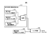
- FIG. 7 is a functional block diagram of the ECU 200 relating to the pressing control. Each functional block shown in FIG. 7 may be realized by hardware or software.
- the ECU 200 includes a permission determination unit 210, a start determination unit 220, and a torque control unit 230.
- the permission determination unit 210 determines whether or not to perform the pressing control according to whether or not the combustion state of the engine 100 is good.
- the permission determination unit 210 includes a first determination unit 211, a second determination unit 212, a third determination unit 213, and a storage unit 214.
- the first to third determination units 211, 212, and 213 each determine whether or not to perform the pressing control depending on whether or not the combustion state is good, but the determination timing and the determination method are different.
- the first determination unit 211 determines whether or not to perform the pressing control based on the combustion state at the time of starting the engine. A specific determination method will be described later.
- the second determination unit 212 determines whether or not to perform the pressing control based on the combustion state at the time of traveling idle. A specific determination method will be described later.
- the third determination unit 213 determines whether or not to perform the pressing control based on the combustion state during the load operation. A specific determination method will be described later.
- the history of determination results of the first to third determination units 211, 212, and 213 are all stored in the storage unit 214.
- the storage unit 214 stores “permission flag F” indicating whether or not execution of the pressing control is permitted. When the permission flag F is “ON”, it indicates that execution of the pressing control is permitted. When the permission flag F is “off”, it indicates that execution of the pressing control is not permitted (prohibited).
- the permission flag F stored in the storage unit 214 is set to “on”, and the combustion state is not good. If it is determined that the condition has deteriorated, the permission flag F stored in the storage unit 214 is set to “off”.
- the case where the combustion state is not good includes the case where the combustion state is unstable and the case where the air-fuel mixture does not burn even when ignited.
- Such a phenomenon is a phenomenon that appears conspicuously when a heavy fuel having a lower volatility than a standard fuel that is a standard for determining the control specifications of the engine 100 is used. Therefore, the determination result (permission flag F) by the first to third determination units 211, 212, and 213 also corresponds to an indication of the nature of the fuel used (whether it is standard fuel or heavy fuel).
- the start determination unit 220 determines whether or not a pressing control start condition is satisfied, specifically, whether or not the vehicle 1 is stopped and the engine 100 is controlled to be in an idle state. Then, the determination result is output to the torque control unit 230.
- the torque control unit 230 reads the permission flag F stored in the storage unit 214 when the pressing control start condition is satisfied. The torque control unit 230 executes the pressing control when the permission flag F is “ON” to generate the pressing torque Tp from the first MG 20, and executes the pressing control when the permission flag F is “OFF”. Therefore, the pressing torque Tp is not generated from the first MG 20.
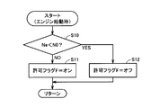
- FIG. 8 is a flowchart showing a processing procedure of the ECU 200 for realizing the function of the first determination unit 211 described above. This flowchart is started when the engine is started.
- the ECU 200 determines whether or not the engine rotation speed Ne continues to be lower than the threshold value N0 until a predetermined time elapses after the engine is started.
- This threshold value N0 is set to a value for determining whether or not the first explosion has been carried out after a predetermined time has elapsed after the engine is started.
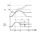
- FIG. 9 is a diagram showing changes in the engine rotation speed Ne and the cranking torque Tcrk at the time of starting the engine. Ignition by the ignition coil 106 is performed at time t1 when the engine rotation speed Ne reaches a predetermined speed by the cranking torque Tcrk. When the initial explosion is performed by this ignition, the engine rotational speed Ne increases exceeding the threshold value N0. When the initial explosion is not performed, the engine rotational speed Ne does not exceed the threshold value N0 and When the ranking torque Tcrk is returned to 0, the engine speed Ne is also reduced to 0 (see the one-dot chain line in FIG. 9).
- ECU 200 continuously generates cranking torque Tcrk to support engine rotational speed Ne so that engine rotational speed Ne does not decrease (hereinafter, this control is also referred to as “supporting control”).
- the “predetermined time” used for the determination in S10 is set to a period ⁇ including the support control period ⁇ . In S10, it may be determined whether or not the support control is executed.
- FIG. 10 is a flowchart showing a processing procedure of the ECU 200 for realizing the function of the second determination unit 212 described above. This flowchart is repeatedly executed in a predetermined cycle when the vehicle is idling.
- the ECU 200 determines whether or not the engine rotation speed Ne is lower than the reference speed N1.
- the reference speed N1 is set to the target idle rotation speed Nisc, for example.
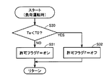
- FIG. 11 is a flowchart showing a processing procedure of the ECU 200 for realizing the function of the third determination unit 213 described above. This flowchart is repeatedly executed in a predetermined cycle during load operation.
- the ECU 200 determines whether or not the engine torque Te is lower than the reference torque T0.
- the engine torque Te may be estimated from Tm1 and Tm2, for example. That is, during load operation, as already described, Tm1 is controlled to a value that takes charge of the reaction force of Te and Tm2. Therefore, the engine torque Te can be estimated from Tm1 and Tm2. Tm1 and Tm2 can be estimated from the detection results of the resolvers 12 and 13.
- the reference torque T0 may be set based on the value of the engine torque Te when combustion is good.
- a correspondence relationship between Tm1 and Tm2 and the engine torque Te when combustion is good is obtained in advance based on the result of an experiment or the like, and the reference torque T0 corresponding to the actual Tm1 and Tm2 using the correspondence relationship. Should be set.
- ECU 200 determines that the combustion state is good, and sets permission flag F to “on” in S31.
- ECU 200 determines that the combustion state is not good and sets permission flag F to “off” in S32.
- FIG. 12 is a flowchart showing a processing procedure of the ECU 200 for realizing the functions of the start determination unit 220 and the torque control unit 230 described above. This flowchart is repeatedly executed in a predetermined cycle while the engine 100 is operating.
- ECU 200 determines whether or not the vehicle is stopped. In S42, ECU 200 determines whether engine 100 is in an idle state or not. In S43, ECU 200 determines whether permission flag F is “ON” or not.
- the ECU 200 executes the pressing control and generates the pressing torque Tp from the first MG 20. Thereby, idle vibration can be suppressed.
- the vehicle 1 determines in advance whether or not the combustion state of the engine 100 is good.
- execution of the pressing control during idling is stopped. Permit, and when the combustion state is not good, the execution of the pushing control at the time of stop idling is prohibited.
- the combustion state of the engine 100 depending on the properties of the fuel used, the balance between suppression of noise caused by idle vibration and stabilization of the operating state of the engine 100 (avoidance of engine stall) is balanced. I can plan well.
- the present embodiment can be modified as follows, for example.
- the vehicle 1 according to the present embodiment includes two motor generators (first MG 20 and second MG 30), but may be a vehicle including one or three motor generators. Further, the vehicle 1 according to the present embodiment does not include a clutch in the drive system, but may be a vehicle provided with a clutch in the drive system.
- the execution of the pressing control is prohibited when the combustion state of the engine 100 is not good.
- the present invention is not limited to the one that prohibits the execution of the pressing control.
- the pressing torque Tp when the combustion state is not good is made smaller than the pressing torque Tp when the combustion state is good (in other words, the pressing torque Tp when the combustion state is good). May be larger than the pressing torque Tp when the combustion state is not good.
- the adjustment of the magnitude of the pressing torque Tp can be realized by controlling the output of the first MG 20, it is not necessarily limited to this.
- the magnitude of pressing torque Tp may be adjusted by changing the slip of the clutch.
Landscapes
- Engineering & Computer Science (AREA)
- Transportation (AREA)
- Mechanical Engineering (AREA)
- Chemical & Material Sciences (AREA)
- Combustion & Propulsion (AREA)
- Automation & Control Theory (AREA)
- Hybrid Electric Vehicles (AREA)
- Control Of Vehicle Engines Or Engines For Specific Uses (AREA)
- Electric Propulsion And Braking For Vehicles (AREA)
Abstract
車両は、エンジンと、第1MG(モータジェネレータ)と、第2MGと、これらを連結する遊星歯車式の動力分割装置と、ECU(200)とを備える。ECU(200)は、許可判定部(210)と、開始判定部(220)と、トルク制御部(230)とを備える。許可判定部(210)は、エンジンの燃焼状態が良好であるか否かに応じて、エンジンのアイドル時に動力分割装置で生じるアイドル振動を抑制するための押し当て制御の実行許否を判定し、判定結果に応じて許可フラグを設定する。開始判定部(220)は、停車中かつアイドル状態であるか否かを判定する。トルク制御部(230)は、停車中かつアイドル状態である場合、許可フラグFが「オン」の場合は押し当て制御を実行して第1MGから押し当てトルクTpを発生させ、「オフ」の場合は押し当て制御を実行せずに第1MGから押し当てトルクTpを発生させない。
Description
本発明は、車両および車両の制御に関する。
特開2008-6945号公報(特許文献1)には、エンジンと電動機とを備えるハイブリッド車両において、電動機からトルクを発生させることによって、エンジントルクの変動に起因して駆動装置に含まれる歯車機構で生じる異音(歯打ち音)を抑制する技術が開示されている。
しかしながら、特許文献1のように異音を抑制するためのトルクを電動機から発生させた場合、エンジンの燃焼状態によっては、エンジンの運転状態が不安定になる場合も考えられる。
本発明は、上述の課題を解決するためになされたものであって、その目的は、内燃機関と内燃機関に歯車機構を介して結合された電動機とを備えた車両において、歯車機構で生じる異音の抑制と内燃機関の運転状態の安定化とをバランス良く図ることである。
この発明に係る車両は、内燃機関と、内燃機関に歯車機構を介して結合された電動機と、電動機を制御する制御装置とを備える。制御装置は、内燃機関がアイドル状態のときに、内燃機関の燃焼状態が良好であるときは、内燃機関の作動を妨げる方向のトルクを電動機から発生させる。
好ましくは、制御装置は、内燃機関がアイドル状態のときに、燃焼状態が良好であるときは、燃焼状態が良好でない場合に比べて、内燃機関の作動を妨げる方向のトルクが大きくなるようにする。
好ましくは、制御装置は、内燃機関がアイドル状態のときに、燃焼状態が良好でないときは、内燃機関の作動を妨げる方向のトルクを電動機から発生させない。
好ましくは、制御装置は、内燃機関の作動中に内燃機関の状態に基づいて燃焼状態が良好であるか否かを判断して判断結果を記憶する。制御装置は、車両が停止した状態で内燃機関がアイドル状態のときに、燃焼状態が良好でないと判断された履歴がないときは内燃機関の作動を妨げる方向のトルクを電動機から発生させ、燃焼状態が良好でないと判断された履歴があるときは内燃機関の作動を妨げる方向のトルクを電動機から発生させない。
好ましくは、制御装置は、内燃機関の始動後から所定時間が経過するまでの間に内燃機関の回転速度が所定速度に達しない場合に、燃焼状態が良好でないと判断して判断結果を記憶する。
好ましくは、制御装置は、電動機がトルクを発生していない状態で内燃機関がアイドル状態である間に内燃機関の回転速度が所定速度よりも低下した場合に、燃焼状態が良好でないと判断して判断結果を記憶する。
好ましくは、制御装置は、内燃機関がアイドル状態のときよりも大きいトルクを出力する負荷運転状態である間に内燃機関のトルクが所定トルクよりも低下した場合に、燃焼状態が良好でないと判断して判断結果を記憶する。
この発明の別の局面の係る車両は、内燃機関と、内燃機関に歯車機構を介して結合された電動機と、電動機を制御する制御装置とを備える。制御装置は、内燃機関がアイドル状態のときに、重質燃料よりも揮発性の良い標準燃料が使用されたときは内燃機関の作動を妨げる方向のトルクを電動機から発生させる。
好ましくは、制御装置は、内燃機関がアイドル状態のときに、標準燃料が使用されたときは、標準燃料よりも揮発性の悪い重質燃料が使用されたときに比べて、内燃機関の作動を妨げる方向のトルクが大きくなるようにする。
好ましくは、制御装置は、内燃機関がアイドル状態のときに、重質燃料が使用されたときは内燃機関の作動を妨げる方向のトルクを電動機から発生させない。
本発明によれば、内燃機関と内燃機関に歯車機構を介して結合された電動機とを備えた車両において、歯車機構で生じる異音の抑制と内燃機関の運転状態の安定化とをバランス良く図ることができる。
以下、本発明の実施例について、図面を参照しながら詳細に説明する。なお、図中同一または相当部分には同一符号を付してその説明は繰返さない。
図1は、本発明の実施例に従う車両1の全体ブロック図である。図1を参照して、この車両1は、エンジン100と、第1MG(Motor Generator)20と、第2MG30と、動力分割装置40と、減速機50と、PCU(Power Control Unit)60と、バッテリ70と、駆動輪80と、ECU(Electronic Control Unit)200とを備える。
エンジン100、第1MG20および第2MG30は、動力分割装置40を介して連結される。そして、この車両1は、エンジン100および第2MG30の少なくとも一方から出力される駆動力によって走行する。エンジン100が発生する動力は、動力分割装置40によって2経路に分割される。すなわち、一方は減速機50を介して駆動輪80へ伝達される経路であり、もう一方は第1MG20へ伝達される経路である。
エンジン100は、ECU200からの制御信号S1(より詳しくはS1a,S1b,S1c)によって制御される内燃機関である。
図2は、エンジン100の詳細を示す図である。なお、図2には1つの気筒が示されているが、実際にはエンジン100には複数の気筒が設けられる。
このエンジン100においては、エアクリーナ(図示せず)から吸入される空気が、吸気管110を流通して、エンジン100の燃焼室102に導入される。
スロットルバルブ114は、ECU200からの制御信号S1aにより制御され、燃焼室102に導入される空気量を調整する。インジェクタ104は、ECU200からの制御信号S1bにより制御され、フューエルタンク(図示せず)に貯蔵された燃料を燃焼室102に噴射する。なお、インジェクタ104から吸気通路内に燃料を噴射するようにしてもよい。イグニッションコイル106は、ECU200からの制御信号S1cにより制御され、燃焼室102内の空気と燃料との混合気に点火して混合気を燃焼させる。
混合気が燃焼した後の排気は、排気管120に送られ、触媒140で浄化された後、大気に排出される。
ECU200には、回転速度センサ11、水温センサ108、振動センサ109、エアフロメータ116、空気温センサ118、空燃比センサ122、および酸素センサ124からの信号が入力されている。
回転速度センサ11は、エンジン回転速度(エンジン100のクランクシャフトの回転速度)Neを検出する。水温センサ108は、エンジン水温THwを検出する。振動センサ109は、エンジン100のシリンダブロックの振動を検出する。エアフロメータ116は、吸入空気量(エンジン100に吸入される単位時間あたりの空気量)Gaを検出する。空気温センサ118は、吸気温THaを検出する。空燃比センサ122は、排気中における空燃比(燃料質量に対する空気質量の比)A/Fを検出する。酸素センサ124は、排気中の酸素濃度を検出する。これらの各センサは、検出結果を表わす信号をECU200に送信する。
図1に戻って、第1MG20および第2MG30は、交流電動機であり、たとえば、三相交流同期電動機である。
動力分割装置40は、サンギヤと、ピニオンギヤと、キャリアと、リングギヤとを含む遊星歯車から成る。ピニオンギヤは、サンギヤおよびリングギヤと係合する。キャリアは、ピニオンギヤを自転可能に支持するとともに、エンジン100のクランクシャフトに連結される。サンギヤは、第1MG20の回転軸に連結される。リングギヤは第2MG30の回転軸および減速機50に連結される。このように、エンジン100、第1MG20および第2MG30が、遊星歯車からなる動力分割装置40を介して連結されることで、エンジン回転速度Ne、第1MG回転速度(第1MG20の回転軸の回転速度)Nm1および第2MG回転速度(第2MG30の回転軸の回転速度)Nm2は、後述する図3~6に示すように、共線図において直線で結ばれる関係になる。
PCU60は、バッテリ70に蓄えられた直流電力を第1MG20および第2MG30を駆動可能な交流電力に変換して第1MG20および/または第2MG30に出力する。これにより、バッテリ70に蓄えられた電力で第1MG20および/または第2MG30が駆動される。また、PCU60は、第1MG20および/または第2MG30によって発電される交流電力をバッテリ70を充電可能な直流電力に変換してバッテリ70へ出力する。これにより、第1MG20および/または第2MG30が発電した電力でバッテリ70が充電される。
バッテリ70は、第1MG20および/または第2MG30を駆動するための電力を蓄える直流電源であり、たとえば、ニッケル水素やリチウムイオン等の二次電池から成る。バッテリ70の電圧は、たとえば200V程度である。なお、バッテリ70として、大容量のキャパシタも採用可能である。
また、ECU200には、上述したエンジン100の状態を検出する各センサ(回転速度センサ11等)の他に、レゾルバ12,13、車速センサ14、アクセルポジションセンサ15などが接続される。
レゾルバ12は、第1MG回転速度Nm1を検出する。レゾルバ13は、第2MG回転速度Nm2を検出する。車速センサ14は、ドライブシャフトの回転速度から車速Vを検出する。アクセルポジションセンサ15は、ユーザによるアクセルペダルの操作量Aを検出する。これらの各センサは、検出結果を表わす信号をECU200に送信する。
ECU200は、図示しないCPU(Central Processing Unit)およびメモリを内蔵し、当該メモリに記憶された情報や各センサからの情報に基づいて、所定の演算処理を実行するように構成される。
ECU200は、車両1の状態に応じて、エンジン100、第1MG20、第2MG30を制御する。なお、以下では、エンジン100のトルクを「エンジントルクTe」、第1MG20のトルクを「第1MGトルクTm1」、第2MG30のトルクを「第2MGトルクTm2」と示す。
図3~6は、いずれも、ECU200によって制御されるエンジン100、第1MG20、第2MG30の状態を共線図上に示した図である。なお、上述したように、エンジン回転速度Ne、第1MG回転速度Nm1、第2MG回転速度Nm2は、共線図において直線で結ばれる関係になる。
図3は、エンジン100の始動時の共線図を示す。なお、図3には、停車時(Nm2=0の時)にエンジン100を始動する場合が示されている。
エンジン100を始動させる際、ECU200は、まず、第1MG20を用いてエンジン100をクランキングする。すなわち、ECU200は、図3に示すように、第1MG20からクランキングトルクTcrkを発生させる(Tm1=Tcrkとする)。そして、ECU200は、クランキングトルクTcrkによってエンジン回転速度Neが所定速度まで上昇した時にイグニッションコイル106による点火を行なう。この点火による混合気の燃焼(いわゆる初爆)が行なわれると、エンジン100が始動され、エンジン100が自ら発生するトルクによってエンジン回転速度Neがさらに上昇される。なお、点火後においてもエンジン回転速度Neがしきい値N0よりも低い場合は、ECU200は、初爆が行なわれていないと判断して、クランキングトルクTcrkを継続して発生させる。
図4は、停車アイドル時(停車時にエンジン100がアイドル状態に制御される場合)の共線図を示す。なお、本実施例で用いる「アイドル状態」とは、低負荷(無負荷を含む)かつ低回転でエンジン100が作動している状態をいうものとする。ECU200は、停車アイドル時には、エンジン回転速度Neが目標アイドル回転速度Niscに近づくようにエンジントルクTe(より詳しくはスロットルバルブ114の操作量)をフィードバック制御する制御を実行する(以下、この制御を「ISC制御」(ISC;Idle Speed Control)という)。
この際、動力分割装置40を構成するギヤ同士の間にガタ(遊び)が存在するため、第1MG20をフリー状態(トルクを発生しない状態)にすると、動力分割装置40を構成するギヤ同士が不定期に当接し比較的低い周波数の振動(以下「アイドル振動」ともいう)が生じる。このアイドル振動に起因する異音は、走行ノイズが生じない停車時には、比較的大きな不快感をユーザに与える場合がある。
このアイドル振動を抑制するために、ECU200は、図4に示すように、動力分割装置40を構成するギヤ同士を互いに押し当てて当接した状態に維持するためのトルク(以下「押し当てトルクTp」という)を第1MG20から発生させる(Tm1=Tpとする)。押し当てトルクTpの大きさは、アイドル振動を抑制可能なように予め実験等によって決められる。したがって、押し当てトルクTpの大きさは、エンジントルクTeやエンジン回転速度Neに関わらず、一定の値に固定される。押し当てトルクTpの向きは、エンジン100の作動を妨げる向き(図4に示す負方向)である。以下では、押し当てトルクTpを第1MG20から発生させる制御を「押し当て制御」という。押し当て制御については後により詳しく説明する。
図5は、走行アイドル時(車両走行中にエンジン100がアイドル状態に制御される場合)の共線図を示す。ECU200は、走行アイドル時においても、上述したISC制御を実行する。そのため、停車時と同様にアイドル振動が生じ得るが、車両走行中は、走行ノイズなども生じるため、アイドル振動がユーザに与える不快感は相対的に小さくなる。そのため、ECU200は、走行アイドル時には、図5に示すように、押し当て制御は行わず、第1MG20をフリー状態にする(Tm1=0とする)。
図6は、負荷運転時(エンジン100がアイドル状態よりも出力が大きい負荷運転状態に制御される場合)の共線図を示す。ECU200は、負荷運転時には、ユーザが要求するトルクを満足するようにエンジントルクTeおよび第2MGトルクTm2を制御する。この際、ECU200は、第1MGトルクTm1がエンジントルクTeおよび第2MGトルクTm2の反力を受け持つように第1MGトルクTm1をフィードバック制御する。したがって、第1MGトルクTm1は、負荷運転時には、エンジントルクTeおよび第2MGトルクTm2に応じて可変に制御される。
以上のように、本実施例においては、車両1の状態に応じて、エンジン100、第1MG20、第2MG30が制御される。特に、停車アイドル時には、押し当て制御が実行されて第1MG20から押し当てトルクTpが発生されるため、アイドル振動が抑制される。
しかしながら、押し当てトルクTpは、図4に示したように、エンジン100の作動を妨げる向き(図4に示す負方向)に作用する。そのため、混合気が燃焼し難くく十分なエンジントルクTeを確保できない場合にまで押し当てトルクTpを発生させると、エンジン100の運転状態が不安定になり、エンジンストールを引き起こす可能性が生じる。
そこで、ECU200は、エンジン100の燃焼状態が良好である否かを予め判定しておき、停車アイドル時に、判定結果が燃焼状態が良好であることを示すときは押し当て制御を実行し、判定結果が燃焼状態が良好でないことを示すときは押し当て制御を実行しないようにする。この点が本発明の最も特徴的な点である。
図7は、押し当て制御に関する部分のECU200の機能ブロック図である。図7に示した各機能ブロックは、ハードウェアによって実現してもよいし、ソフトウェアによって実現してもよい。
ECU200は、許可判定部210と、開始判定部220と、トルク制御部230とを備える。
許可判定部210は、エンジン100の燃焼状態が良好であるか否かに応じて、押し当て制御の実行許否を判定する。
許可判定部210は、第1判定部211、第2判定部212、第3判定部213、記憶部214を含む。第1~3判定部211,212,213は、いずれも燃焼状態が良好であるか否かに応じて押し当て制御の実行許否を判定するものであるが、判定時期および判定手法が異なる。
第1判定部211は、エンジン始動時の燃焼状態に基づいて押し当て制御の実行許否を判定する。具体的な判定手法については後述する。
第2判定部212は、走行アイドル時の燃焼状態に基づいて押し当て制御の実行許否を判定する。具体的な判定手法については後述する。
第3判定部213は、負荷運転時の燃焼状態に基づいて押し当て制御の実行許否を判定する。具体的な判定手法については後述する。
第1~3判定部211,212,213の判定結果の履歴は、いずれも記憶部214に記憶される。具体的には、記憶部214には、押し当て制御の実行を許可するか否かを示す「許可フラグF」が記憶されている。許可フラグFが「オン」の場合は、押し当て制御の実行が許可されていることを示す。許可フラグFが「オフ」の場合は、押し当て制御の実行が許可されていない(禁止されている)ことを示す。
第1~3判定部211,212,213の各々は、燃焼状態が良好であると判定した場合、記憶部214に記憶されている許可フラグFを「オン」に設定し、燃焼状態が良好でない(悪化している)と判定した場合、記憶部214に記憶されている許可フラグFを「オフ」に設定する。
なお、燃焼状態が良好でない場合とは、燃焼状態が不安定な場合や、点火しても混合気が燃焼しない場合を含む。このような現象は、エンジン100の制御仕様を決める際の規準となる標準燃料よりも揮発性の悪い重質燃料が使用される場合に顕著に現れる現象である。したがって、第1~3判定部211,212,213による判定結果(許可フラグF)は、使用される燃料の性状(標準燃料であるのか重質燃料であるのか)を示すものにも相当する。
開始判定部220は、押し当て制御の開始条件が成立したか否か、具体的には、車両1が停車中であってかつエンジン100がアイドル状態に制御される場合であるか否かを判定し、判定結果をトルク制御部230に出力する。
トルク制御部230は、押し当て制御の開始条件が成立すると、記憶部214に記憶されている許可フラグFを読み出す。トルク制御部230は、許可フラグFが「オン」の場合は押し当て制御を実行して第1MG20から押し当てトルクTpを発生させ、許可フラグFが「オフ」の場合は押し当て制御を実行せずに第1MG20から押し当てトルクTpを発生させない。
図8は、上述の第1判定部211の機能を実現するためのECU200の処理手順を示すフローチャートである。このフローチャートは、エンジン始動時に開始される。
S10にて、ECU200は、エンジン始動後から所定時間が経過するまでの間にエンジン回転速度Neがしきい値N0よりも低い状態が継続したか否かを判断する。このしきい値N0は、エンジン始動後から所定時間が経過するまでの間に初爆が行なわれたかを判断するための値に設定される。
図9は、エンジン始動時のエンジン回転速度NeおよびクランキングトルクTcrkの変化を示す図である。クランキングトルクTcrkによってエンジン回転速度Neが所定速度に達した時刻t1でイグニッションコイル106による点火が行なわれる。この点火によって初爆が行なわれた場合はエンジン回転速度Neがしきい値N0を超えて上昇するが、初爆が行なわれていない場合はエンジン回転速度Neがしきい値N0を超えず、クランキングトルクTcrkを0に戻すとエンジン回転速度Neも0に低下してしまう(図9の一点鎖線参照)。そのため、ECU200は、時刻t2以降は、エンジン回転速度Neが低下しないようエンジン回転速度Neを下支えするためにクランキングトルクTcrkを継続して発生させる(以下、この制御を「下支え制御」ともいう)。S10での判断に用いられる「所定時間」は、この下支え制御の期間βを含んだ期間αに設定される。なお、S10で下支え制御の実行の有無そのものを判断するようにしてもよい。
図8に戻って、エンジン回転速度Neがしきい値N0よりも高くなった場合(S10にてNO)、ECU200は、燃焼状態が良好である(初爆が行なわれた)と判断して、S11にて許可フラグFを「オン」に設定する。一方、エンジン回転速度Neがしきい値N0よりも低い状態が継続している場合(S10にてYES)、ECU200は、燃焼状態が良好でない(初爆が行なわれていない)と判断して、S12にて許可フラグFを「オフ」に設定する。
図10は、上述の第2判定部212の機能を実現するためのECU200の処理手順を示すフローチャートである。このフローチャートは、走行アイドル時に所定サイクルで繰り返し実行される。
S20にて、ECU200は、エンジン回転速度Neが基準速度N1よりも低いか否かを判断する。基準速度N1は、たとえば目標アイドル回転速度Niscに設定される。
エンジン回転速度Neが基準速度N1よりも高い場合(S20にてNO)、ECU200は、燃焼状態が良好であると判断して、S21にて許可フラグFを「オン」に設定する。一方、エンジン回転速度Neが基準速度N1よりも低い場合(S20にてYES)、ECU200は、燃焼状態が良好でないと判断して、S22にて許可フラグFを「オフ」に設定する。
図11は、上述の第3判定部213の機能を実現するためのECU200の処理手順を示すフローチャートである。このフローチャートは、負荷運転時に所定サイクルで繰り返し実行される。
S30にて、ECU200は、エンジントルクTeが基準トルクT0よりも低いか否かを判断する。エンジントルクTeは、たとえば、Tm1、Tm2から推定すればよい。すなわち、負荷運転時には、既に述べたように、Tm1がTeおよびTm2の反力を受け持つ値に制御される。そのため、エンジントルクTeは、Tm1、Tm2から推定することが可能である。Tm1、Tm2は、レゾルバ12,13の検出結果などから推定することが可能である。また、基準トルクT0は、燃焼良好時のエンジントルクTeの値を基準として設定すればよい。たとえば、実験等の結果に基づいてTm1、Tm2と燃焼良好時のエンジントルクTeとの対応関係を予め求めて記憶しておき、その対応関係を用いて実際のTm1、Tm2に対応する基準トルクT0を設定するようにすればよい。
エンジントルクTeが基準トルクT0よりも高い場合(S30にてNO)、ECU200は、燃焼状態が良好であると判断して、S31にて許可フラグFを「オン」に設定する。一方、エンジントルクTeが基準トルクT0よりも低い場合(S30にてYES)、ECU200は、燃焼状態が良好でないと判断して、S32にて許可フラグFを「オフ」に設定する。
図12は、上述の開始判定部220およびトルク制御部230の機能を実現するためのECU200の処理手順を示すフローチャートである。このフローチャートは、エンジン100の作動中に所定サイクルで繰り返し実行される。
S41にて、ECU200は、停車中であるか否かを判断する。S42にて、ECU200は、エンジン100がアイドル状態であるか否かを判断する。S43にて、ECU200は、許可フラグFが「オン」であるか否かを判断する。
停車アイドル時であってかつ許可フラグFがオンである場合(S41~S43のいずれにおいてもYES)、ECU200は、押し当て制御を実行し、押し当てトルクTpを第1MG20から発生させる。これにより、アイドル振動を抑制することができる。
一方、車両走行中である場合(S40にてNO)、またはエンジン100が負荷運転中である場合(S41にてNO)、または許可フラグFがオフである場合(S43にてNO)、ECU200は、押し当て制御を実行せずに、押し当てトルクTpを第1MG20から発生させない。すなわち、停車アイドル時であっても、燃焼状態が良好でないと判定されていた場合、ECU200は、押し当て制御の実行を禁止する。これにより、エンジン100の運転状態を安定させる(エンジンストールを回避する)ことができる。
以上のように、本実施例に従う車両1は、エンジン100の燃焼状態が良好であるか否かを予め判定しておき、燃焼状態が良好であるときは停車アイドル時の押し当て制御の実行を許可し、燃焼状態が良好でないときは停車アイドル時の押し当て制御の実行を禁止する。これにより、エンジン100の燃焼状態に応じて(使用される燃料の性状に応じて)、アイドル振動に起因する異音の抑制とエンジン100の運転状態の安定化(エンジンストールの回避)とをバランス良く図ることができる。
なお、本実施例は、たとえば以下のように変更することもできる。
本実施例に従う車両1は2つのモータジェネレータ(第1MG20および第2MG30)を備えていたが、1つまたは3つのモータジェネレータを備える車両であってもよい。また、本実施例に従う車両1は駆動系にクラッチを備えていないが、駆動系にクラッチを備える車両であってもよい。
本実施例に従う車両1は2つのモータジェネレータ(第1MG20および第2MG30)を備えていたが、1つまたは3つのモータジェネレータを備える車両であってもよい。また、本実施例に従う車両1は駆動系にクラッチを備えていないが、駆動系にクラッチを備える車両であってもよい。
また、本実施例では、エンジン100の燃焼状態が良好でないときに押し当て制御の実行を禁止していたが、本発明は押し当て制御の実行を禁止するものに限定されない。たとえば、燃焼状態が良好でないときの押し当てトルクTpが燃焼状態が良好であるときの押し当てトルクTpに比べて小さくなるようにする(言い換えれば、燃焼状態が良好であるときの押し当てトルクTpが燃焼状態が良好でないときの押し当てトルクTpよりも大きくなるようにする)ようにしてもよい。
また、押し当てトルクTpの大きさの調整は、第1MG20の出力を制御することによって実現可能であるが、必ずしもこれに限定されない。たとえば、第1MG20と動力分割装置40との間にクラッチが設けられる場合には、クラッチのすべりを変更することにより、押し当てトルクTpの大きさを調整するようにしてもよい。
今回開示された実施例はすべての点で例示であって制限的なものではないと考えられるべきである。本発明の範囲は上記した説明ではなくて請求の範囲によって示され、請求の範囲と均等の意味および範囲内でのすべての変更が含まれることが意図される。
1 車両、11 回転速度センサ、12,13 レゾルバ、14 車速センサ、15 アクセルポジションセンサ、20 第1MG、30 第2MG、40 動力分割装置、50 減速機、70 バッテリ、80 駆動輪、100 エンジン、102 燃焼室、104 インジェクタ、106 イグニッションコイル、108 水温センサ、109 振動センサ、110 吸気管、114 スロットルバルブ、116 エアフロメータ、118 空気温センサ、120 排気管、122 空燃比センサ、124 酸素センサ、140 触媒、200 ECU、210 許可判定部、211 第1判定部、212 第2判定部、213 第3判定部、214 記憶部、220 開始判定部、230 トルク制御部。
Claims (10)
- 内燃機関(100)と、
前記内燃機関に歯車機構(40)を介して結合された電動機(20)と、
前記電動機を制御する制御装置(200)とを備え、
前記制御装置は、前記内燃機関がアイドル状態のときに、前記内燃機関の燃焼状態が良好であるときは、前記内燃機関の作動を妨げる方向のトルクを前記電動機から発生させる、車両。 - 前記制御装置は、前記内燃機関がアイドル状態のときに、前記燃焼状態が良好であるときは、前記燃焼状態が良好でない場合に比べて、前記内燃機関の作動を妨げる方向のトルクが大きくなるようにする、請求項1に記載の車両。
- 前記制御装置は、前記内燃機関がアイドル状態のときに、前記燃焼状態が良好でないときは、前記内燃機関の作動を妨げる方向のトルクを前記電動機から発生させない、請求項2に記載の車両。
- 前記制御装置は、前記内燃機関の作動中に前記内燃機関の状態に基づいて前記燃焼状態が良好であるか否かを判断して判断結果を記憶し、
前記制御装置は、前記車両が停止した状態で前記内燃機関がアイドル状態のときに、前記燃焼状態が良好でないと判断された履歴がないときは前記内燃機関の作動を妨げる方向のトルクを前記電動機から発生させ、前記燃焼状態が良好でないと判断された履歴があるときは前記内燃機関の作動を妨げる方向のトルクを前記電動機から発生させない、請求項3に記載の車両。 - 前記制御装置は、前記内燃機関の始動後から所定時間が経過するまでの間に前記内燃機関の回転速度が所定速度に達しない場合に、前記燃焼状態が良好でないと判断して判断結果を記憶する、請求項4に記載の車両。
- 前記制御装置は、前記電動機がトルクを発生していない状態で前記内燃機関がアイドル状態である間に前記内燃機関の回転速度が所定速度よりも低下した場合に、前記燃焼状態が良好でないと判断して判断結果を記憶する、請求項4に記載の車両。
- 前記制御装置は、前記内燃機関がアイドル状態のときよりも大きいトルクを出力する負荷運転状態である間に前記内燃機関のトルクが所定トルクよりも低下した場合に、前記燃焼状態が良好でないと判断して判断結果を記憶する、請求項4項に記載の車両。
- 内燃機関(100)と、
前記内燃機関に歯車機構(40)を介して結合された電動機(20)と、
前記電動機を制御する制御装置(200)とを備え、
前記制御装置は、前記内燃機関がアイドル状態のときに、重質燃料よりも揮発性の良い標準燃料が使用されたときは前記内燃機関の作動を妨げる方向のトルクを前記電動機から発生させる、車両。 - 前記制御装置は、前記内燃機関がアイドル状態のときに、前記標準燃料が使用されたときは、前記重質燃料が使用されたときに比べて、前記内燃機関の作動を妨げる方向のトルクが大きくなるようにする、請求項8に記載の車両。
- 前記制御装置は、前記内燃機関がアイドル状態のときに、前記重質燃料が使用されたときは前記内燃機関の作動を妨げる方向のトルクを前記電動機から発生させない、請求項9に記載の車両。
Priority Applications (5)
| Application Number | Priority Date | Filing Date | Title |
|---|---|---|---|
| CN201080070864.0A CN103269928B (zh) | 2010-12-22 | 2010-12-22 | 车辆及车辆的控制方法 |
| US13/996,121 US8989938B2 (en) | 2010-12-22 | 2010-12-22 | Vehicle and vehicle control method |
| PCT/JP2010/073085 WO2012086022A1 (ja) | 2010-12-22 | 2010-12-22 | 車両および車両の制御方法 |
| JP2012549521A JP5494825B2 (ja) | 2010-12-22 | 2010-12-22 | 車両および車両の制御方法 |
| EP10861136.9A EP2657099B1 (en) | 2010-12-22 | 2010-12-22 | Vehicle and vehicle control method |
Applications Claiming Priority (1)
| Application Number | Priority Date | Filing Date | Title |
|---|---|---|---|
| PCT/JP2010/073085 WO2012086022A1 (ja) | 2010-12-22 | 2010-12-22 | 車両および車両の制御方法 |
Publications (1)
| Publication Number | Publication Date |
|---|---|
| WO2012086022A1 true WO2012086022A1 (ja) | 2012-06-28 |
Family
ID=46313326
Family Applications (1)
| Application Number | Title | Priority Date | Filing Date |
|---|---|---|---|
| PCT/JP2010/073085 Ceased WO2012086022A1 (ja) | 2010-12-22 | 2010-12-22 | 車両および車両の制御方法 |
Country Status (5)
| Country | Link |
|---|---|
| US (1) | US8989938B2 (ja) |
| EP (1) | EP2657099B1 (ja) |
| JP (1) | JP5494825B2 (ja) |
| CN (1) | CN103269928B (ja) |
| WO (1) | WO2012086022A1 (ja) |
Cited By (5)
| Publication number | Priority date | Publication date | Assignee | Title |
|---|---|---|---|---|
| CN107344551A (zh) * | 2016-05-05 | 2017-11-14 | 通用汽车环球科技运作有限责任公司 | 发动机脉冲扭矩消除命令的控制 |
| JP2018118677A (ja) * | 2017-01-26 | 2018-08-02 | トヨタ自動車株式会社 | ハイブリッド車両の制御装置 |
| JP2019038463A (ja) * | 2017-08-28 | 2019-03-14 | トヨタ自動車株式会社 | ハイブリッド自動車 |
| JP2020189569A (ja) * | 2019-05-22 | 2020-11-26 | トヨタ自動車株式会社 | ハイブリッド車両の制御装置 |
| JP2024082186A (ja) * | 2022-12-07 | 2024-06-19 | トヨタ自動車株式会社 | 車両の制御装置 |
Families Citing this family (7)
| Publication number | Priority date | Publication date | Assignee | Title |
|---|---|---|---|---|
| EP2631101B1 (de) * | 2012-02-22 | 2016-06-08 | MAGNA STEYR Fahrzeugtechnik AG & Co KG | Hybridantrieb |
| JP6372493B2 (ja) * | 2016-01-14 | 2018-08-15 | トヨタ自動車株式会社 | ハイブリッド車両の制御装置 |
| US10906523B2 (en) * | 2016-07-22 | 2021-02-02 | Shindengen Electric Manufacturing Co., Ltd. | Control apparatus and control method for hybrid vehicle |
| JP6856050B2 (ja) * | 2018-04-25 | 2021-04-07 | トヨタ自動車株式会社 | 内燃機関及びそれを備えたハイブリッド車両 |
| JP7135476B2 (ja) * | 2018-06-13 | 2022-09-13 | 三菱自動車工業株式会社 | 車両の発電制御装置 |
| JP7243420B2 (ja) * | 2019-05-07 | 2023-03-22 | トヨタ自動車株式会社 | 車両 |
| JP7663071B2 (ja) | 2021-12-13 | 2025-04-16 | トヨタ自動車株式会社 | ハイブリッド車 |
Citations (7)
| Publication number | Priority date | Publication date | Assignee | Title |
|---|---|---|---|---|
| JP2001251704A (ja) | 2000-03-07 | 2001-09-14 | Jatco Transtechnology Ltd | パラレルハイブリッド車両 |
| JP2002180863A (ja) | 2000-12-14 | 2002-06-26 | Toyota Motor Corp | 車輌駆動系振動の制振装置 |
| JP2005207378A (ja) * | 2004-01-26 | 2005-08-04 | Toyota Motor Corp | エンジンの制御装置 |
| JP2005271706A (ja) | 2004-03-24 | 2005-10-06 | Jatco Ltd | パラレルハイブリッド車両 |
| JP2008006945A (ja) | 2006-06-28 | 2008-01-17 | Toyota Motor Corp | ハイブリッド車両の制御装置 |
| JP2009191752A (ja) * | 2008-02-14 | 2009-08-27 | Toyota Motor Corp | 内燃機関の排気還流装置 |
| JP2010126064A (ja) * | 2008-11-28 | 2010-06-10 | Toyota Motor Corp | 内燃機関の失火判定装置および内燃機関の失火判定方法 |
Family Cites Families (4)
| Publication number | Priority date | Publication date | Assignee | Title |
|---|---|---|---|---|
| JP3354074B2 (ja) * | 1997-04-25 | 2002-12-09 | ジヤトコ株式会社 | パラレルハイブリッド車両の制御装置 |
| CN1159519C (zh) | 1998-12-24 | 2004-07-28 | 丰田自动车株式会社 | 内燃机的输出状态检测装置 |
| US6494277B1 (en) * | 2000-11-09 | 2002-12-17 | Ford Motor Company | Hybrid electric vehicle system |
| US8463476B2 (en) * | 2009-11-30 | 2013-06-11 | Toyota Jidosha Kabushiki Kaisha | Hybrid vehicle control apparatus |
-
2010
- 2010-12-22 JP JP2012549521A patent/JP5494825B2/ja active Active
- 2010-12-22 EP EP10861136.9A patent/EP2657099B1/en not_active Not-in-force
- 2010-12-22 CN CN201080070864.0A patent/CN103269928B/zh not_active Expired - Fee Related
- 2010-12-22 US US13/996,121 patent/US8989938B2/en not_active Expired - Fee Related
- 2010-12-22 WO PCT/JP2010/073085 patent/WO2012086022A1/ja not_active Ceased
Patent Citations (7)
| Publication number | Priority date | Publication date | Assignee | Title |
|---|---|---|---|---|
| JP2001251704A (ja) | 2000-03-07 | 2001-09-14 | Jatco Transtechnology Ltd | パラレルハイブリッド車両 |
| JP2002180863A (ja) | 2000-12-14 | 2002-06-26 | Toyota Motor Corp | 車輌駆動系振動の制振装置 |
| JP2005207378A (ja) * | 2004-01-26 | 2005-08-04 | Toyota Motor Corp | エンジンの制御装置 |
| JP2005271706A (ja) | 2004-03-24 | 2005-10-06 | Jatco Ltd | パラレルハイブリッド車両 |
| JP2008006945A (ja) | 2006-06-28 | 2008-01-17 | Toyota Motor Corp | ハイブリッド車両の制御装置 |
| JP2009191752A (ja) * | 2008-02-14 | 2009-08-27 | Toyota Motor Corp | 内燃機関の排気還流装置 |
| JP2010126064A (ja) * | 2008-11-28 | 2010-06-10 | Toyota Motor Corp | 内燃機関の失火判定装置および内燃機関の失火判定方法 |
Cited By (10)
| Publication number | Priority date | Publication date | Assignee | Title |
|---|---|---|---|---|
| CN107344551A (zh) * | 2016-05-05 | 2017-11-14 | 通用汽车环球科技运作有限责任公司 | 发动机脉冲扭矩消除命令的控制 |
| CN107344551B (zh) * | 2016-05-05 | 2020-02-11 | 通用汽车环球科技运作有限责任公司 | 发动机脉冲扭矩消除命令的控制 |
| JP2018118677A (ja) * | 2017-01-26 | 2018-08-02 | トヨタ自動車株式会社 | ハイブリッド車両の制御装置 |
| CN108357490A (zh) * | 2017-01-26 | 2018-08-03 | 丰田自动车株式会社 | 混合动力车辆的控制装置 |
| US10527159B2 (en) | 2017-01-26 | 2020-01-07 | Toyota Jidosha Kabushiki Kaisha | Control device of hybrid vehicle |
| CN108357490B (zh) * | 2017-01-26 | 2021-03-05 | 丰田自动车株式会社 | 混合动力车辆的控制装置 |
| JP2019038463A (ja) * | 2017-08-28 | 2019-03-14 | トヨタ自動車株式会社 | ハイブリッド自動車 |
| JP2020189569A (ja) * | 2019-05-22 | 2020-11-26 | トヨタ自動車株式会社 | ハイブリッド車両の制御装置 |
| JP7211264B2 (ja) | 2019-05-22 | 2023-01-24 | トヨタ自動車株式会社 | ハイブリッド車両の制御装置 |
| JP2024082186A (ja) * | 2022-12-07 | 2024-06-19 | トヨタ自動車株式会社 | 車両の制御装置 |
Also Published As
| Publication number | Publication date |
|---|---|
| CN103269928A (zh) | 2013-08-28 |
| EP2657099B1 (en) | 2018-04-25 |
| JP5494825B2 (ja) | 2014-05-21 |
| CN103269928B (zh) | 2015-09-30 |
| US20130268153A1 (en) | 2013-10-10 |
| US8989938B2 (en) | 2015-03-24 |
| EP2657099A1 (en) | 2013-10-30 |
| JPWO2012086022A1 (ja) | 2014-05-22 |
| EP2657099A4 (en) | 2014-08-20 |
Similar Documents
| Publication | Publication Date | Title |
|---|---|---|
| JP5494825B2 (ja) | 車両および車両の制御方法 | |
| JP4183013B1 (ja) | 車両およびその制御方法 | |
| JP4197038B2 (ja) | ハイブリッド自動車およびその制御方法 | |
| JP4175371B2 (ja) | 内燃機関装置およびその制御方法並びに動力出力装置 | |
| JP2010179780A (ja) | ハイブリッド車およびその制御方法 | |
| JP2013193533A (ja) | ハイブリッド車 | |
| JP5716425B2 (ja) | ハイブリッド自動車 | |
| JP5578242B2 (ja) | 車両および車両の制御方法 | |
| JP2007192114A (ja) | 車両及びその制御方法 | |
| JP2010241386A (ja) | ハイブリッド車両およびその制御方法 | |
| JP2013154699A (ja) | 車両用制御装置 | |
| JP5494398B2 (ja) | ハイブリッド自動車 | |
| JP5655693B2 (ja) | ハイブリッド自動車 | |
| JP2011084202A (ja) | 動力出力装置、それを備えたハイブリッド車両および動力出力装置の制御方法 | |
| JP2010105626A (ja) | 車両およびその制御方法 | |
| JP4811323B2 (ja) | 車両およびその制御方法 | |
| JP2011235750A (ja) | ハイブリッド自動車 | |
| JP2009279965A (ja) | ハイブリッド車およびその制御方法 | |
| JP2008232072A (ja) | 車両およびその制御方法 | |
| JP6398943B2 (ja) | 車両 | |
| JP2007120382A (ja) | 動力出力装置およびその制御方法並びに車両 | |
| JP4962404B2 (ja) | 内燃機関装置および車両並びに内燃機関装置の制御方法 | |
| JP4311469B2 (ja) | 車両およびその制御方法 | |
| JP6459916B2 (ja) | 車両 | |
| JP2008247266A (ja) | 車両およびその制御方法 |
Legal Events
| Date | Code | Title | Description |
|---|---|---|---|
| 121 | Ep: the epo has been informed by wipo that ep was designated in this application |
Ref document number: 10861136 Country of ref document: EP Kind code of ref document: A1 |
|
| ENP | Entry into the national phase |
Ref document number: 2012549521 Country of ref document: JP Kind code of ref document: A |
|
| WWE | Wipo information: entry into national phase |
Ref document number: 13996121 Country of ref document: US |
|
| NENP | Non-entry into the national phase |
Ref country code: DE |