WO2012086314A1 - Mécanisme de blocage en rotation pour engrenage - Google Patents
Mécanisme de blocage en rotation pour engrenage Download PDFInfo
- Publication number
- WO2012086314A1 WO2012086314A1 PCT/JP2011/075380 JP2011075380W WO2012086314A1 WO 2012086314 A1 WO2012086314 A1 WO 2012086314A1 JP 2011075380 W JP2011075380 W JP 2011075380W WO 2012086314 A1 WO2012086314 A1 WO 2012086314A1
- Authority
- WO
- WIPO (PCT)
- Prior art keywords
- insertion member
- gear
- tooth
- lock mechanism
- rotation lock
- Prior art date
- Legal status (The legal status is an assumption and is not a legal conclusion. Google has not performed a legal analysis and makes no representation as to the accuracy of the status listed.)
- Ceased
Links
Images


Classifications
-
- F—MECHANICAL ENGINEERING; LIGHTING; HEATING; WEAPONS; BLASTING
- F16—ENGINEERING ELEMENTS AND UNITS; GENERAL MEASURES FOR PRODUCING AND MAINTAINING EFFECTIVE FUNCTIONING OF MACHINES OR INSTALLATIONS; THERMAL INSULATION IN GENERAL
- F16D—COUPLINGS FOR TRANSMITTING ROTATION; CLUTCHES; BRAKES
- F16D63/00—Brakes not otherwise provided for; Brakes combining more than one of the types of groups F16D49/00 - F16D61/00
- F16D63/006—Positive locking brakes
-
- F—MECHANICAL ENGINEERING; LIGHTING; HEATING; WEAPONS; BLASTING
- F16—ENGINEERING ELEMENTS AND UNITS; GENERAL MEASURES FOR PRODUCING AND MAINTAINING EFFECTIVE FUNCTIONING OF MACHINES OR INSTALLATIONS; THERMAL INSULATION IN GENERAL
- F16D—COUPLINGS FOR TRANSMITTING ROTATION; CLUTCHES; BRAKES
- F16D2121/00—Type of actuator operation force
- F16D2121/18—Electric or magnetic
- F16D2121/20—Electric or magnetic using electromagnets
- F16D2121/22—Electric or magnetic using electromagnets for releasing a normally applied brake
-
- F—MECHANICAL ENGINEERING; LIGHTING; HEATING; WEAPONS; BLASTING
- F16—ENGINEERING ELEMENTS AND UNITS; GENERAL MEASURES FOR PRODUCING AND MAINTAINING EFFECTIVE FUNCTIONING OF MACHINES OR INSTALLATIONS; THERMAL INSULATION IN GENERAL
- F16H—GEARING
- F16H35/00—Gearings or mechanisms with other special functional features
- F16H2035/006—Gearings or mechanisms for stopping or limiting movement, e.g. stopping a movement after a few turns
Definitions
- the present invention relates to a gear rotation lock mechanism that locks the rotation of a gear.
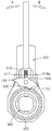
- the rotation lock mechanism of the gear of patent document 1 is a mechanism used in a screw type clamp. As shown in FIG. 10, the gear rotation lock mechanism includes a switching latch 114, and a ball 117 and a spring 118 that hold the switching latch 114 in a first position (see FIG. 10) and a second position. ing. Then, the ball 117 presses the first receiving surface 114a of the switching latch 114, and the first protrusion 115 of the switching latch 114 is engaged with the gear 102 (first position). Rotation of the handle 110 in the right direction (B arrow) is prohibited. That is, the rotating body 100 can be rotated rightward (B arrow) by the handle 110.
- the left rotation (A arrow) of the handle 110 with respect to the rotating body 100 is allowed, and the handle 110 is rotated left (A arrow) while the rotating body 100 is held by a member to be tightened (not shown). be able to.
- the switching latch 114 is switched to the second position, that is, the ball 117 presses the second receiving surface 114b of the switching latch 114 and the second protrusion 116 is engaged with the gear 102,
- the left rotation (A arrow) of the handle 110 with respect to the rotating body 100 is prohibited, and the right rotation (B arrow) is allowed against the spring 118.
- the gear rotation lock mechanism described above cannot lock the gear in both forward and reverse directions.
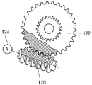
- a configuration using the meshing action of the worm 120 and the worm wheel 122 is conceivable as shown in FIG. That is, the worm wheel 122 can be locked in both the forward and reverse directions by stopping the worm 120 with the motor 124.
- this configuration for example, when the worm 120 is held in a stopped state due to a failure of the motor 124 or the like, there is a problem that the rotation lock of the worm wheel 122 cannot be released.
- the present invention has been made to solve the above-mentioned problems, and the problem to be solved by the present invention is that the gear can be locked in both forward and reverse directions and can be easily unlocked. Is to do so.
- the invention of claim 1 is inserted into a tooth gap of a gear and inserted into another tooth gap of the gear, and a first insertion member capable of holding down the tooth surface of the tooth constituting the tooth groove, Insert a second insertion member capable of holding down the tooth surface of another tooth constituting the tooth gap, and the first insertion member and the second insertion member into the corresponding tooth gap, or the tooth
- An actuator configured to be able to be pulled out from the groove, the forward rotation of the gear is prohibited in a state where the first insertion member presses the tooth surface of the tooth, and the second insertion member is The reverse rotation of the gear is prohibited in a state where the tooth surface of another tooth is pressed.
- the first insertion member and the second insertion member are inserted into the corresponding tooth spaces by the operation of the actuator, respectively, and the tooth surface of the tooth is pressed by the first insertion member, The tooth surface of the other tooth can be pressed by the insertion member.
- normal rotation and reverse rotation of the gear are prohibited. That is, the gear can be locked in both forward and reverse directions.
- the gear can be easily unlocked by pulling out the first insertion member and the second insertion member from the corresponding tooth spaces by the operation of the actuator.
- the first insertion member and the second insertion member are arranged so as to intersect with each other, and the intersecting portion is connected so as to be relatively rotatable by the connection pin,
- the two insertion members rotate relative to each other so that the distal end portion of the first insertion member and the distal end portion of the second insertion member approach each other, whereby the distal end portion of the first insertion member and the second insertion portion
- the tip of the member is configured to be inserted into a corresponding tooth groove of the gear.
- the first insertion member and the second insertion member are formed with elongated hole-shaped cam holes through which the connection pins pass, and the functions of the connection pins and the cam holes are as follows.
- the movement trajectory between the distal end portion of the first insertion member and the distal end portion of the second insertion member is set.
- the first insertion member and the second insertion member are configured to receive the rotational force of the gear at the end face in the longitudinal direction, and the rotational force of the gear is the first insertion member or the first insertion member.
- the first insertion member and the second insertion member are arranged so as to be added in the longitudinal direction of the two insertion members. That is, the rotational force of the gear is applied to the first insertion member or the second insertion member so as to press the first insertion member and the second insertion member from the longitudinal direction. Accordingly, the rotational force of the gear can be received at the portion where the strength of the first insertion member or the second insertion member is the greatest, and the first insertion member and the second insertion member are thinned to reduce the weight. It becomes possible to plan.
- the actuator includes an elastic body that constantly biases the first insertion member and the second insertion member in the insertion direction. For this reason, it is possible to move the first insertion member and the second insertion member in the pulling direction against the elastic force of the elastic body, and the lock can be released even when the actuator fails.
- the actuator includes a solenoid that moves the first insertion member and the second insertion member in the pull-out direction against the elastic force of the elastic body.
- the gear can be locked in both forward and reverse directions.
- the lock can be easily released.
- FIG. 3 A side view showing lock release operation
- movement of the rotation lock mechanism of a gearwheel It is a model side view showing the normal lock operation
- movement of the rotation lock mechanism of a gearwheel It is a model side view showing the normal lock operation
- the gear rotation lock mechanism according to the first embodiment of the present invention will be described below with reference to FIGS.
- the gear rotation lock mechanism according to the present embodiment is a mechanism for locking the rotation of the pinion of the rack and pinion mechanism used in the table slide mechanism.
- the front, rear, left, right, and top and bottom described in the figure correspond to the front, back, left, right, and top and bottom of the table slide mechanism.
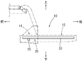
- the table slide mechanism 10 is a mechanism for sliding the horizontal movable table 12 back and forth with respect to the table support base 14 as shown in the schematic diagram of FIG.
- the table slide mechanism 10 includes a rack and pinion mechanism 20 as a drive mechanism for sliding the movable table 12 back and forth. As shown in FIGS.
- the rack and pinion mechanism 20 includes a rack 22 fixed to the lower surface of the movable table 12 so as to extend in the front-rear direction, a motor fixed to the table support base 14 side, and The pinion 25 is fixed to an output shaft 24p of a speed reducer 24 (hereinafter referred to as a motor 24), and a gear rotation lock mechanism 30 that locks the rotation of the pinion 25.
- a speed reducer 24 hereinafter referred to as a motor 24
- the gear rotation lock mechanism 30 is a mechanism for locking the pinion 25 in both forward and reverse directions.
- the gear rotation lock mechanism 30 includes a first insertion member 31, a second insertion member 32, a coupling mechanism 34, a solenoid 36, and a coil spring. 38.
- the first insertion member 31 is a member that prohibits counterclockwise rotation (forward rotation) of the pinion 25, and as shown in FIG.
- the base end portion of the first insertion member 31 has a semicircular end surface, and a through hole 31k is formed in the base end portion of the first insertion member 31 so as to be coaxial with the semicircle. Yes.
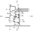
- the support pin part 15p of the 1st support member 15 fixed to the vertical wall 14w of the table support stand 14 is penetrated by the through-hole 31k of the 1st insertion member 31 as shown in FIG.
- the first support member 15 is fixed at a right angle to the vertical wall 14 w of the table support base 14, and a ring-shaped step 15 d is provided at the tip of the first support member 15.
- the support pin portion 15p is formed coaxially. With the support pin portion 15p of the first support member 15 inserted through the through hole 31k of the first insertion member 31, the ring-shaped step 15d presses the back surface of the first insertion member 31, and the support pin portion 15p
- the removal prevention ring 15r of the first insertion member 31 is attached to the tip of the first insertion member 31. Accordingly, the first insertion member 31 can be turned up and down around the support pin portion 15p of the first support member 15. As shown in FIG.
- an elongated cam hole 31a is formed at a position near the tip of the center of the first insertion member 31. Further, an insertion corner portion 31k configured to be insertable into the tooth groove 25m of the pinion 25 is formed at the distal end portion of the first insertion member 31. And the front end surface 31f of the insertion corner
- the second insertion member 32 is a member that prohibits the right rotation (reverse rotation) of the pinion 25, and is formed symmetrically with the first insertion member 31 as shown in FIG. That is, a through hole 32k is formed in the base end portion of the second insertion member 32, and the second hole fixed to the vertical wall 14w of the table support gantry 14 in the through hole 32k as shown in FIG. A support pin portion 16p of the support member 16 is inserted.
- the second support member 16 is fixed at a right angle to the vertical wall 14 w of the table support base 14 at a position diagonally forward and upward of the first support member 15.
- the support pin part 16p is coaxially formed in the front-end
- the support pin portion 16p of the second support member 16 is inserted through the through hole 32k of the second insertion member 32, and the support pin portion 16p
- the removal prevention ring 16r of the second insertion member 32 is attached to the tip.
- the second insertion member 32 can be turned up and down around the support pin portion 16 p of the second support member 16.
- a slotted cam hole 32a is formed at a position near the center of the second insertion member 32, and a tooth groove 25m of the pinion 25 is formed at the tip.
- An insertion corner portion 32k configured to be insertable is formed.
- angular part 32k is comprised so that abutment with the tooth surface 25e of the pinion 25 is possible.
- the connection mechanism 34 is a mechanism for connecting the intersection of the first insertion member 31 and the second insertion member 32 to the solenoid 36 as shown in FIG.
- the coupling mechanism 34 includes a strip-shaped coupling bar 34b and a coupling pin 34p, and the coupling bar 34b is located between the first insertion member 31 and the second insertion member 32 as shown in FIG. Is arranged.
- a connecting pin 34p formed so as to protrude perpendicularly from the front surface and the back surface of the connecting bar 34b is provided at the tip position of the connecting bar 34b.
- the connection pin 34p which protruded to the surface side of the connection bar 34b is penetrated by the cam hole 31a of the 1st insertion member 31, as shown to FIG. 3 (A).
- the connecting pin 34p protruding to the back side of the connecting bar 34b is inserted through the cam hole 32a of the second insertion member 32 as shown in FIG.
- the first insertion member 31 and the second insertion member 32 are connected to each other so as to be rotatable relative to each other by the action of the connection pin 34p and the cam holes 31a and 32a.
- a pin hole 34n is formed at the base end portion of the connecting bar 34b, and the base end portion of the connecting bar 34b is connected to the drive shaft 36j of the solenoid 36 using the pin hole 34n. It is connected by a split pin 36p (see FIG. 1).
- the solenoid 36 includes a solenoid body 36m and the drive shaft 36j.
- the solenoid body 36m is attached to a predetermined position of the vertical wall 14w (see FIG. 4) of the table support base 14 so that the drive shaft 36j of the solenoid 36 is disposed on the extension line of the connection bar 34b of the connection mechanism 34. Yes.
- a coil spring 38 is mounted around the drive shaft 36j of the solenoid 36.
- the coil spring 38 is biased so that the drive shaft 36j protrudes from the solenoid body 36m in the axial direction in a state where the energization of the solenoid body 36m is released.
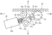
- the solenoid body 36m is energized, the drive shaft 36j is pulled into the solenoid body 36m against the spring force of the coil spring 38.
- the connecting pin 34p pulls the inner wall surfaces of the cam holes 31a, 32a of the first insertion member 31 and the second insertion member 32 obliquely downward in the front direction.
- the first insertion member 31 rotates to the left about the support pin portion 15p
- the second insertion member 32 rotates to the right about the support pin portion 16p.
- the insertion corner portion 31k of the first insertion member 31 and the insertion corner portion 32k of the second insertion member 32 are each pulled out from the tooth groove 25m of the pinion 25. As a result, the rotation lock of the pinion 25 is released.
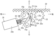
- the first insertion member 31 rotates to the right around the support pin portion 15p
- the second insertion member 32 rotates to the left around the support pin portion 16p.
- the distal end portion of the first insertion member 31 and the distal end portion of the second insertion member 32 move toward the pinion 25 (moves rearward and obliquely upward) while approaching each other, so that the first insertion member 31 is moved.
- One tooth 25z of the pinion 25 is sandwiched between the distal end portion of the second insertion member 32 and the distal end portion of the second insertion member 32.
- the insertion corner portion 31k of the first insertion member 31 and the insertion corner portion 32k of the second insertion member 32 are respectively inserted into the tooth grooves 25m of the pinion 25 formed on both sides of the teeth 25z. Thereby, the rotation of the pinion 25 is locked.
- the pinion 25 when the pinion 25 is rotated rightward (reversely) in the rotation locked state shown in FIG. 6, the pinion 25 is positioned next to the lower side of the tooth 25 z sandwiched between the first insertion member 31 and the second insertion member 32.
- the tooth surface 25e of the tooth 25z comes into contact with the distal end surface 32f (see FIG. 7) of the second insertion member 32.
- the right rotation (reverse rotation) of the pinion 25 is prohibited.
- the rotational force of the pinion 25 is applied in the longitudinal direction of the second insertion member 32.
- the teeth 25 z of the pinion 25 are sandwiched between the distal end portion of the first insertion member 31 and the distal end portion of the second insertion member 32. Even in this case, if the tooth surface 25e of the adjacent tooth 25z on the sandwiched tooth 25z is in contact with the distal end surface 31f of the first insertion member 31, the left rotation (forward rotation) of the pinion 25 is prohibited. . Further, when the pinion 25 rotates rightward (reversely) from this state, the tooth surface 25e of the tooth 25z adjacent to the sandwiched tooth 25z comes into contact with the tip surface 32f of the second insertion member 32, Right rotation (reverse rotation) of the pinion 25 is prohibited.
- the two teeth 25z of the pinion 25 are sandwiched between the distal end portion of the first insertion member 31 and the distal end portion of the second insertion member 32 as shown in FIG.
- the pinion 25 is rotated and locked after being rotated by one tooth 25z. That is, when the pinion 25 rotates counterclockwise (forward rotation), the sandwiched lower teeth 25z are disengaged from between the first insertion member 31 and the second insertion member 32, and adjacent to the sandwiched teeth 25z.
- the tooth surface 25e of the tooth 25z abuts on the distal end surface 31f of the first insertion member 31. Thereby, the left rotation (forward rotation) of the pinion 25 is prohibited.
- the first insertion member 31 and the second insertion member 32 are respectively inserted into the corresponding tooth grooves 25m by the operations of the solenoid 36 and the coil spring 38 (actuator).
- the tooth surface 25e of the tooth 25z can be pressed by the first insertion member 31, and the tooth surface 25e of another tooth 25z can be pressed by the second insertion member 32.
- normal rotation and reverse rotation of the pinion 25 (gear) are prohibited. That is, the pinion 25 (gear) can be locked in both forward and reverse directions.
- the operation of the solenoid 36 makes it possible to easily unlock the pinion 25 (gear) by pulling out the first insertion member 31 and the second insertion member 32 from the corresponding tooth spaces 25m.
- the first insertion member 31 and the second insertion member 32 are coupled via the coupling pin 34p, the first insertion member 31 and the second insertion member 32 are simultaneously coupled to one actuator (solenoid). 36 etc.). Further, the rotational force of the pinion 25 is applied to the first insertion member 31 or the second insertion member 32 so as to press the first insertion member 31 and the second insertion member 32 from the longitudinal direction. Become. For this reason, the rotational force of the pinion 25 can be received at the portion where the strength of the first insertion member 31 or the second insertion member 32 is the largest, and the first insertion member 31 and the second insertion member 32 are It is possible to reduce the thickness by reducing the thickness. Further, since the first insertion member 31 and the second insertion member 32 can be moved in the pulling direction against the spring force of the coil spring 38 in the rotation locked state, when the solenoid 36 fails Etc. can be unlocked.
- the present invention is not limited to the above-described embodiment, and modifications can be made without departing from the gist of the present invention.
- the first insertion member 31 and the second insertion member 32 are crossed and connected by a connection pin 34p, and both the insertion members 31 and 32 are operated simultaneously by a single solenoid 36. Indicated.
- a configuration in which two sets of solenoids 36 are provided and the first insertion member 31 and the second insertion member 32 are individually operated by each solenoid 36 is also possible.
- first insertion member 31 and the second insertion member 32 are individually operated, the first insertion member 31 and the second insertion member 32 are connected to one end side and the other side with the center of the pinion 25 interposed therebetween. It is also possible to arrange them on the end side.
- the rotation lock mechanism of the pinion 25 of the rack and pinion mechanism 20 has been described.
- the present invention can also be applied to a circular gear other than the pinion 25.
Landscapes
- Engineering & Computer Science (AREA)
- General Engineering & Computer Science (AREA)
- Mechanical Engineering (AREA)
- Transmission Devices (AREA)
- Lock And Its Accessories (AREA)
Abstract
Priority Applications (1)
| Application Number | Priority Date | Filing Date | Title |
|---|---|---|---|
| CN201180028875.7A CN103003594B (zh) | 2010-12-21 | 2011-11-04 | 齿轮的旋转锁定机构 |
Applications Claiming Priority (2)
| Application Number | Priority Date | Filing Date | Title |
|---|---|---|---|
| JP2010284557A JP5533634B2 (ja) | 2010-12-21 | 2010-12-21 | 歯車の回転ロック機構 |
| JP2010-284557 | 2010-12-21 |
Publications (1)
| Publication Number | Publication Date |
|---|---|
| WO2012086314A1 true WO2012086314A1 (fr) | 2012-06-28 |
Family
ID=46313597
Family Applications (1)
| Application Number | Title | Priority Date | Filing Date |
|---|---|---|---|
| PCT/JP2011/075380 Ceased WO2012086314A1 (fr) | 2010-12-21 | 2011-11-04 | Mécanisme de blocage en rotation pour engrenage |
Country Status (3)
| Country | Link |
|---|---|
| JP (1) | JP5533634B2 (fr) |
| CN (1) | CN103003594B (fr) |
| WO (1) | WO2012086314A1 (fr) |
Cited By (2)
| Publication number | Priority date | Publication date | Assignee | Title |
|---|---|---|---|---|
| JP2018201884A (ja) * | 2017-06-06 | 2018-12-27 | 兆軒 何 | 移動補助具 |
| CN112088074A (zh) * | 2019-04-15 | 2020-12-15 | 株式会社虹之机器 | 驱动轴制动装置 |
Families Citing this family (4)
| Publication number | Priority date | Publication date | Assignee | Title |
|---|---|---|---|---|
| CN107407435A (zh) * | 2015-02-12 | 2017-11-28 | 伊顿公司 | 具有放大行程的螺线管 |
| JP2018161010A (ja) * | 2017-03-23 | 2018-10-11 | 株式会社デンソー | 可動装置、その製造方法、および、その制御方法 |
| CN107947059B (zh) * | 2017-12-13 | 2020-12-08 | 桐庐火炎医疗器械有限公司 | 一种通讯线缆支撑杆的升高机构 |
| WO2026030776A1 (fr) * | 2024-08-09 | 2026-02-12 | Ktm Ag | Dispositif de verrouillage de boîte de vitesses |
Citations (5)
| Publication number | Priority date | Publication date | Assignee | Title |
|---|---|---|---|---|
| JPS517794B1 (fr) * | 1970-04-09 | 1976-03-11 | ||
| JPS6394331U (fr) * | 1986-12-09 | 1988-06-17 | ||
| DE19901688A1 (de) * | 1999-01-18 | 2000-07-20 | Continental Teves Ag & Co Ohg | Sperrvorrichtung für einen Antriebsstrang |
| JP2006198377A (ja) * | 2005-01-21 | 2006-08-03 | Araya Industrial Co Ltd | 車椅子用バンドブレーキ |
| JP2008180263A (ja) * | 2007-01-24 | 2008-08-07 | Takahashi Riken:Kk | 動力伝達装置 |
Family Cites Families (1)
| Publication number | Priority date | Publication date | Assignee | Title |
|---|---|---|---|---|
| US7438661B2 (en) * | 2006-02-15 | 2008-10-21 | Eaton Corporation | Mechanical locking differential lockout mechanism |
-
2010
- 2010-12-21 JP JP2010284557A patent/JP5533634B2/ja active Active
-
2011
- 2011-11-04 WO PCT/JP2011/075380 patent/WO2012086314A1/fr not_active Ceased
- 2011-11-04 CN CN201180028875.7A patent/CN103003594B/zh active Active
Patent Citations (5)
| Publication number | Priority date | Publication date | Assignee | Title |
|---|---|---|---|---|
| JPS517794B1 (fr) * | 1970-04-09 | 1976-03-11 | ||
| JPS6394331U (fr) * | 1986-12-09 | 1988-06-17 | ||
| DE19901688A1 (de) * | 1999-01-18 | 2000-07-20 | Continental Teves Ag & Co Ohg | Sperrvorrichtung für einen Antriebsstrang |
| JP2006198377A (ja) * | 2005-01-21 | 2006-08-03 | Araya Industrial Co Ltd | 車椅子用バンドブレーキ |
| JP2008180263A (ja) * | 2007-01-24 | 2008-08-07 | Takahashi Riken:Kk | 動力伝達装置 |
Cited By (5)
| Publication number | Priority date | Publication date | Assignee | Title |
|---|---|---|---|---|
| JP2018201884A (ja) * | 2017-06-06 | 2018-12-27 | 兆軒 何 | 移動補助具 |
| CN112088074A (zh) * | 2019-04-15 | 2020-12-15 | 株式会社虹之机器 | 驱动轴制动装置 |
| EP3756837A4 (fr) * | 2019-04-15 | 2021-06-09 | Rainbow Robotics | Dispositif de freinage d'un arbre de commande |
| US11313424B2 (en) | 2019-04-15 | 2022-04-26 | Rainbow Robotics | Braking device for driving shaft |
| CN112088074B (zh) * | 2019-04-15 | 2023-10-24 | 株式会社虹之机器 | 驱动轴制动装置 |
Also Published As
| Publication number | Publication date |
|---|---|
| CN103003594A (zh) | 2013-03-27 |
| CN103003594B (zh) | 2016-05-04 |
| JP2012132497A (ja) | 2012-07-12 |
| JP5533634B2 (ja) | 2014-06-25 |
Similar Documents
| Publication | Publication Date | Title |
|---|---|---|
| JP5533634B2 (ja) | 歯車の回転ロック機構 | |
| JP6860359B2 (ja) | 接続構造及びそれを備えたled表示装置 | |
| CN102632292B (zh) | 一种斜切锯 | |
| WO2019073854A1 (fr) | Dispositif actionneur de verrouillage d'orifice pour entrée de véhicule | |
| JP2010110887A (ja) | 電動工具 | |
| GB2434113A (en) | Clamping device for disc-shaped tool with locking mechanism | |
| CN101837747B (zh) | 用于汽车座椅的锁紧装置 | |
| JP2010501385A (ja) | 特に航空機における構造部分の着脱可能な連結のための装置および方法 | |
| CN102131603B (zh) | 转塔刀架 | |
| JP2013508576A (ja) | 可動家具部を変位させる2体の作動装置を同期させる同期装置 | |
| WO2019073855A1 (fr) | Dispositif actionneur de verrouillage de port pour entrée de véhicule | |
| EP1918562A3 (fr) | Ensemble d'anneau de verrouillage bidirectionnel pour unité de commande manuelle d'inverseur de poussée d'un avion | |
| JP7083353B2 (ja) | 車両インレット用ポートロックアクチュエータ装置 | |
| WO2023025620A1 (fr) | Agencement pour outil électrique, accessoire de partie avant et outil électrique | |
| TW201425780A (zh) | 行星齒輪組切換機構 | |
| CA2939754A1 (fr) | Raccord | |
| DE102012111132A1 (de) | Elektrische Lenkradsperre | |
| JP4890652B1 (ja) | 送りネジ式手動ステージ | |
| JP4716344B2 (ja) | 工作機械用締め付けチャック | |
| CN101564833A (zh) | 棘轮扳手的换向结构 | |
| JP6989700B2 (ja) | 断路器用操作装置 | |
| CN203532719U (zh) | 防跳挡变挡机构 | |
| JP5418831B2 (ja) | 位置調整式操舵装置 | |
| JP2012110988A (ja) | シャーレンチ用ソケット及びシャーレンチ | |
| JP3208792U (ja) | キャスタ装置および収納ラック |
Legal Events
| Date | Code | Title | Description |
|---|---|---|---|
| WWE | Wipo information: entry into national phase |
Ref document number: 201180028875.7 Country of ref document: CN |
|
| WWE | Wipo information: entry into national phase |
Ref document number: 1201006448 Country of ref document: TH |
|
| 121 | Ep: the epo has been informed by wipo that ep was designated in this application |
Ref document number: 11850604 Country of ref document: EP Kind code of ref document: A1 |
|
| NENP | Non-entry into the national phase |
Ref country code: DE |
|
| 122 | Ep: pct application non-entry in european phase |
Ref document number: 11850604 Country of ref document: EP Kind code of ref document: A1 |